development and operation of a prototype cone-beam computed tomography system for x-ray medical...
TRANSCRIPT
Journal of the Korean Physical Society, Vol. 64, No. 1, January 2014, pp. 129∼134
Development and Operation of a Prototype Cone-beam ComputedTomography system for X-ray Medical Imaging
Chang-Woo Seo, Bo Kyung Cha, Ryun Kyung Kim, Cho-RongKim, Keedong Yang, Young Huh and Sungchae Jeon∗
Advanced Medical Device Research Center, Korea Electrotechnology Research Institute, Ansan 426-910, Korea
Justin C. Park, Bongyong Song and William Y. Song
Center for Advanced Radiotherapy Technologies and Department of Radiation Medicine and Applied Sciences,University of California San Diego, California 92093, USA
(Received 25 July 2013, in final form 28 August 2013)
This paper describes the development of a prototype cone-beam computed tomography (CBCT)system for clinical use. The overall system design in terms of physical characteristics, geometriccalibration methods, and three-dimensional image reconstruction algorithms are described. Oursystem consists of an X-ray source and a large-area flat-panel detector with the axial dimensionlarge enough for most clinical applications when acquired in a full gantry rotation mode. Variouselaborate methods are applied to measure, analyze and calibrate the system for imaging. The elec-tromechanical and the radiographic subsystems through the synchronized control include: gantryrotation and speed, tube rotor, the high-frequency generator (kVp, mA, exposure time and repe-tition rate), and the reconstruction server (imaging acquisition and reconstruction). The operatorcan select between analytic and iterative reconstruction methods. Our prototype system containsthe latest hardware and reconstruction algorithms and, thus, represents a step forward in CBCTtechnology.
PACS numbers: 87.57.Gg, 87.57.-s, 87.80.Tq, 87.80.-yKeywords: Cone-beam computed tomography, Geometric calibration, Interface synchronization, Three-dimensional reconstruction, X-ray imaging systemDOI: 10.3938/jkps.64.129
I. INTRODUCTION
For several decades, computed tomography (CT) the-ory, techniques, and applications have undergone rapiddevelopment. Practical and useful CT technology, whichwill be continuously advanced for higher performancesystems and more improved image reconstruction al-gorithms, has been intensely pursued for importantbiomedical and non-biomedical applications [1]. Con-ventional medical CT uses a fan-shaped X-ray beam inhelical/spiral-scan geometries to acquire individual im-age slices of the field of view (FOV) and then stacksthe slices to obtain a three-dimensional (3D) image [2].The major design considerations include cost, access, andimaging dose [3].
All current generations of cone-beam computed to-mography (CBCT) systems provide useful diagnostic im-ages. The CBCT system uses a rotating gantry in whichan X-ray source and detector are fixed. The X-raysource and detector rotate around a rotation fulcrum
∗E-mail: [email protected]
fixed within the center of the region of interest on theopposite side. Because the CBCT system incorporatesthe entire FOV, only one rotation sequence of the gantryis necessary to acquire enough projection images for 3Dcone-beam reconstruction in a complete or limited arc[4]. However, its main disadvantage, especially withlarger FOVs, is a limitation in image quality related tonoise and contrast resolution because of the detection oflarge amounts of scattered radiation [2].
In the early 2000 s, flat-panel volume CT (VCT),which is based on a modification of a commercially-available gantry, was revised to achieve larger volumecoverage and higher spatial resolution [5, 6]. Also,commercially-available spiral CT used as the basis for aCBCT imaging prototype for performing phantom, an-imal and patient imaging studies [7]. However, CBCTmade by modifying conventional CT is indicated by anover-specification. A mobile C-arm-based CBCT systemprovides multi-mode fluoroscopy and CBCT imaging ca-pability [8,9]. However, C-arm-based CBCT is seriouslyaffected by image artifacts related to the limited numberof rotational projections and the gantry motion [4].
-129-
-130- Journal of the Korean Physical Society, Vol. 64, No. 1, January 2014
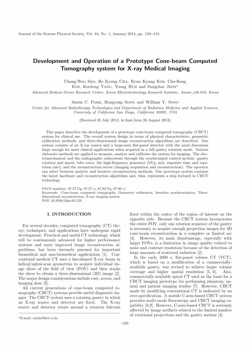
Fig. 1. (Color online) Block diagram of a prototype CBCTsystem.
We have developed and operated a prototype CBCTsystem for various geometry calibration methods andcone-beam reconstruction algorithms and for potentialclinical benefits. Our system uses a scan arc of 360◦ toacquire projection images. The electromechanical andthe radiographic subsystems through the synchronizedcontrol include: the gantry rotation and speed, the tuberotor, the high-frequency generator (kVp, mA, exposuretime, and repetition rate), and the reconstruction server(imaging acquisition and reconstruction). The 3D re-construction server can select between analytic and iter-ative reconstructions initiated with analytic reconstruc-tion for 3D reconstructed images. Our prototype systemhas been developed and operated to identify, analyze,and update the potential problems of CBCT system.
II. MATERIAL AND METHODS
1. Development of a Prototype CBCT System
A schematic diagram of a prototype CBCT system isshown in Fig. 1. A prototype CBCT consists of a robotgantry (gantry rotator and operation drive), an X-raysource (a wide-angle X-ray tube, filters and a collima-tor), a detector (a large-area flat panel detector (FPD)and anti-scatter grid), a main controller (user touch con-sole, main control board, command processor (CP)), anda reconstruction server (frame grabber (LVDS), graph-ics processing unit (GPU), and reconstruction and viewsoftware). The main control board was designed by us-ing a field programmable gate array (FPGA) to controlthe synchronized interface signal from among the usertouch console, robot gantry, detector, and reconstructionserver.
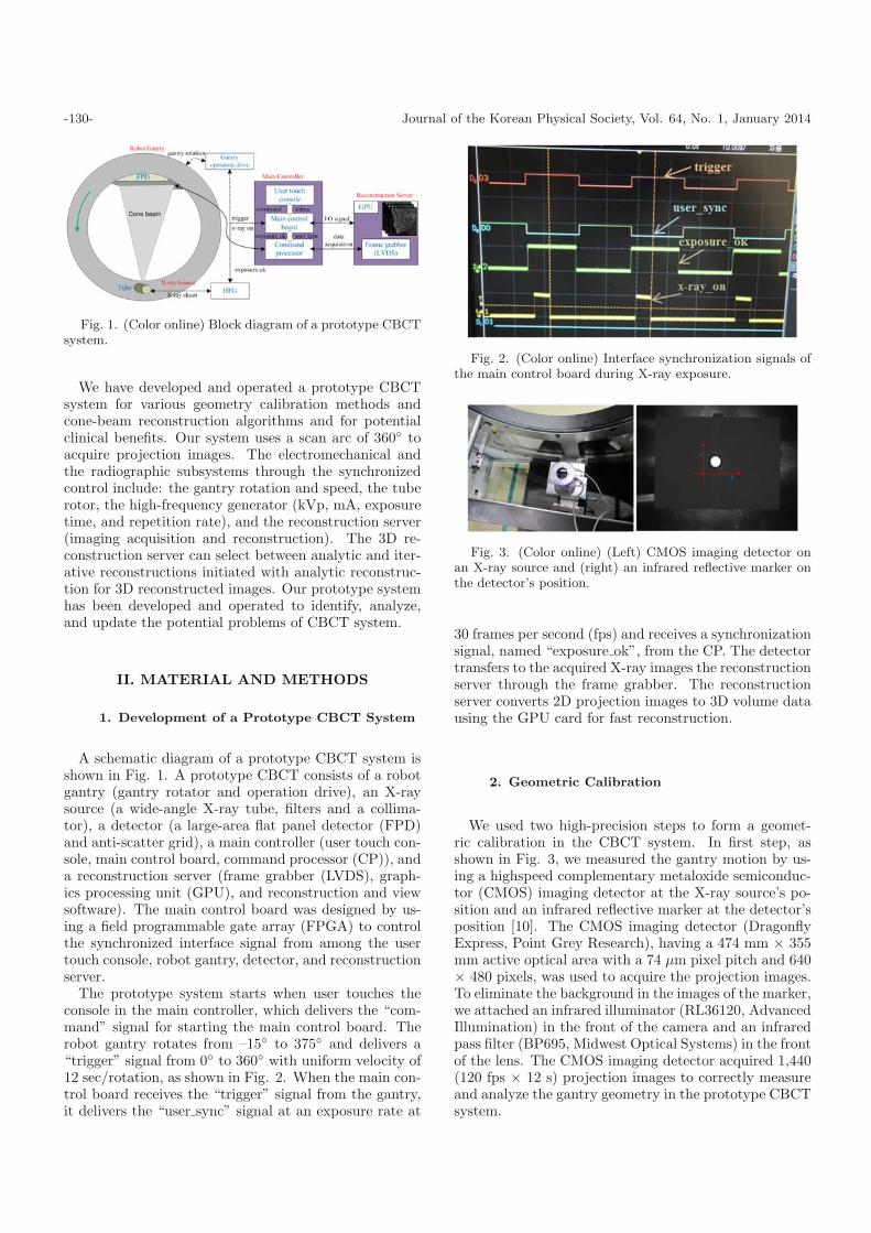
The prototype system starts when user touches theconsole in the main controller, which delivers the “com-mand” signal for starting the main control board. Therobot gantry rotates from –15◦ to 375◦ and delivers a“trigger” signal from 0◦ to 360◦ with uniform velocity of12 sec/rotation, as shown in Fig. 2. When the main con-trol board receives the “trigger” signal from the gantry,it delivers the “user sync” signal at an exposure rate at
Fig. 2. (Color online) Interface synchronization signals ofthe main control board during X-ray exposure.
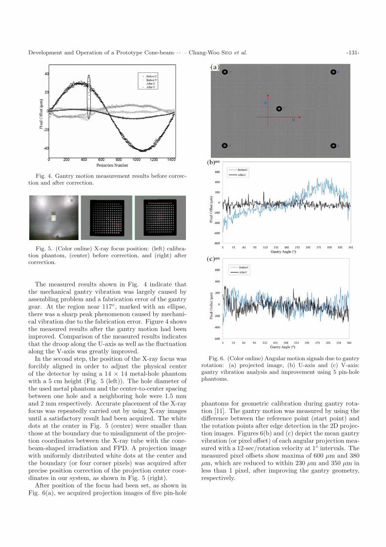
Fig. 3. (Color online) (Left) CMOS imaging detector onan X-ray source and (right) an infrared reflective marker onthe detector’s position.
30 frames per second (fps) and receives a synchronizationsignal, named “exposure ok”, from the CP. The detectortransfers to the acquired X-ray images the reconstructionserver through the frame grabber. The reconstructionserver converts 2D projection images to 3D volume datausing the GPU card for fast reconstruction.
2. Geometric Calibration
We used two high-precision steps to form a geomet-ric calibration in the CBCT system. In first step, asshown in Fig. 3, we measured the gantry motion by us-ing a highspeed complementary metaloxide semiconduc-tor (CMOS) imaging detector at the X-ray source’s po-sition and an infrared reflective marker at the detector’sposition [10]. The CMOS imaging detector (DragonflyExpress, Point Grey Research), having a 474 mm × 355mm active optical area with a 74 µm pixel pitch and 640× 480 pixels, was used to acquire the projection images.To eliminate the background in the images of the marker,we attached an infrared illuminator (RL36120, AdvancedIllumination) in the front of the camera and an infraredpass filter (BP695, Midwest Optical Systems) in the frontof the lens. The CMOS imaging detector acquired 1,440(120 fps × 12 s) projection images to correctly measureand analyze the gantry geometry in the prototype CBCTsystem.
Development and Operation of a Prototype Cone-beam· · · – Chang-Woo Seo et al. -131-
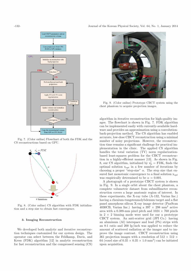
Fig. 4. Gantry motion measurement results before correc-tion and after correction.
Fig. 5. (Color online) X-ray focus position: (left) calibra-tion phantom, (center) before correction, and (right) aftercorrection.
The measured results shown in Fig. 4 indicate thatthe mechanical gantry vibration was largely caused byassembling problem and a fabrication error of the gantrygear. At the region near 117◦, marked with an ellipse,there was a sharp peak phenomenon caused by mechani-cal vibration due to the fabrication error. Figure 4 showsthe measured results after the gantry motion had beenimproved. Comparison of the measured results indicatesthat the droop along the U-axis as well as the fluctuationalong the V-axis was greatly improved.
In the second step, the position of the X-ray focus wasforcibly aligned in order to adjust the physical centerof the detector by using a 14 × 14 metal-hole phantomwith a 5 cm height (Fig. 5 (left)). The hole diameter ofthe used metal phantom and the center-to-center spacingbetween one hole and a neighboring hole were 1.5 mmand 2 mm respectively. Accurate placement of the X-rayfocus was repeatedly carried out by using X-ray imagesuntil a satisfactory result had been acquired. The whitedots at the center in Fig. 5 (center) were smaller thanthose at the boundary due to misalignment of the projec-tion coordinates between the X-ray tube with the cone-beam-shaped irradiation and FPD. A projection imagewith uniformly distributed white dots at the center andthe boundary (or four corner pixels) was acquired afterprecise position correction of the projection center coor-dinates in our system, as shown in Fig. 5 (right).
After position of the focus had been set, as shown inFig. 6(a), we acquired projection images of five pin-hole
Fig. 6. (Color online) Angular motion signals due to gantryrotation: (a) projected image, (b) U-axis and (c) V-axis:gantry vibration analysis and improvement using 5 pin-holephantoms.
phantoms for geometric calibration during gantry rota-tion [11]. The gantry motion was measured by using thedifference between the reference point (start point) andthe rotation points after edge detection in the 2D projec-tion images. Figures 6(b) and (c) depict the mean gantryvibration (or pixel offset) of each angular projection mea-sured with a 12-sec/rotation velocity at 1◦ intervals. Themeasured pixel offsets show maxima of 600 µm and 380µm, which are reduced to within 230 µm and 350 µm inless than 1 pixel, after improving the gantry geometry,respectively.
-132- Journal of the Korean Physical Society, Vol. 64, No. 1, January 2014
Fig. 7. (Color online) Flowchart of both the FDK and theCS reconstructions based on GPU.
Fig. 8. (Color online) CS algorithm with FDK initializa-tion and a step size to obtain fast convergence.
3. Imaging Reconstruction
We developed both analytic and iterative reconstruc-tion techniques customized for our system design. Theoperator can select between the Feldkamp, Davis, andKress (FDK) algorithm [12] in analytic reconstructionfor fast reconstruction and the compressed sensing (CS)
Fig. 9. (Color online) Prototype CBCT system using thechest phantom to acquire projection images.
algorithm in iterative reconstruction for high-quality im-ages. The flowchart is shown in Fig. 7. FDK algorithmcan be implemented easily with currently-available hard-ware and provides an approximation using a convolution-back-projection method. The CS algorithm has enabledaccurate, low-dose CBCT reconstruction using a minimalnumber of noisy projections. However, the reconstruc-tion time remains a significant challenge for practical im-plementation in the clinic. The applied CS algorithmhandles the total variation (TV) norm regularization-based least-squares problem for the CBCT reconstruc-tion in a highly-efficient manner [13]. As shown in Fig.8, our CS algorithm, initialized by x′
0 = FDK, finds theoptimal solution xopt in a few number of iterations bychoosing a proper “step-size” α. The step size that en-sured fast monotonic convergence to a final solution xopt
was empirically determined to be α = 0.001.A photograph of a prototype CBCT system is shown
in Fig. 9. In a single orbit about the chest phantom, acomplete volumetric dataset from submillimeter recon-struction covers a large anatomic region of interest. Inthese experiments, the X-ray tube (A-132, Varian Inc.)having a rhenium-tungstenmolybdenum target and a flatpanel amorphous silicon X-ray image detector (PaxScan4030CB, Varian Inc.) having a 397 × 298 mm2 activearea with a 0.388-mm pixel pitch and 1024 × 768 pixelsin 2 × 2 binning mode were used for our a prototypeCBCT system. An anti-scatter grid (JPI Co.) havingan aluminum (Al) interspace and lead (Pb) strips withan 8:1 ratio and 200 lp/inch was applied to reduce theamount of scattered radiation at the imager and to im-prove the image contrast. CBCT reconstruction using361 projection images with a resolution of 512 × 512 ×64 (voxel size of 0.35 × 0.35 × 1.0 mm3) can be initiatedupon acquisition.
Development and Operation of a Prototype Cone-beam· · · – Chang-Woo Seo et al. -133-
Table 1. Specifications of a prototype CBCT system.
Robot gantry
Rotate angle 0◦ ∼ 360◦ (one rotation)
Speed 12 sec/rotation
Dist. focus to detector 1330 mm
Dist. focus to isocenter 660 mm
X-ray sourceTube voltage 40 ∼ 120 kVp
Tube current 10 ∼ 500 mA
Exposure duration 10 ms (Pulsed mode)
Flat panel detector
Number of Pixels 1024 × 768 (40 × 30 cm2)
Pixel size 0.388 × 0.388 mm2 (2 × 2 binning mode)
Frame rate Max 30 fps
Dynamic range 14 bit/ADC
Recon. server
Projection number 361 (1◦) interval)
Image voxels 0.35 × 0.35 × 1.0 mm3
Voxel number 512 × 512 × 64
GPU 1024 block size
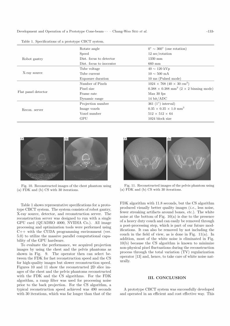
Fig. 10. Reconstructed images of the chest phantom using(a) FDK and (b) CS with 30 iterations.
Table 1 shows representative specifications for a proto-type CBCT system. The system consists of robot gantry,X-ray source, detector, and reconstruction server. Thereconstruction server was designed to run with a singleGPU card (QUADRO 4000, NVIDIA Co.). All imageprocessing and optimization tools were performed usingC++ with the CUDA programming environment (ver.5.0) to utilize the massive parallel computational capa-bility of the GPU hardware.
To evaluate the performance, we acquired projectionimages by using the chest and the pelvis phantoms asshown in Fig. 9. The operator then can select be-tween the FDK for fast reconstruction speed and the CSfor high-quality images but slower reconstruction speed.Figures 10 and 11 show the reconstructed 2D slice im-ages of the chest and the pelvis phantoms reconstructedwith the FDK and the CS algorithms. For the FDKalgorithm, a ramp filter was used for processing noiseprior to the back projection. For the CS algorithm, atypical reconstruction speed achieved was 490 secondswith 30 iterations, which was far longer than that of the
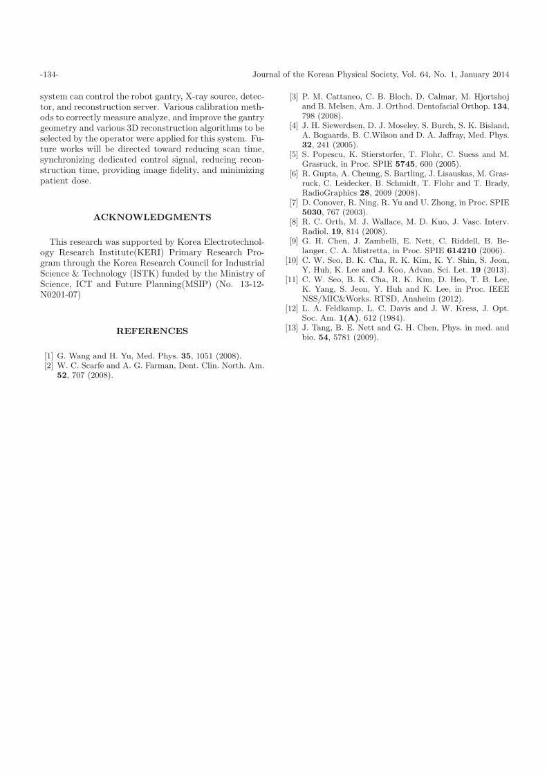
Fig. 11. Reconstructed images of the pelvis phantom using(a) FDK and (b) CS with 30 iterations.
FDK algorithm with 11.8 seconds, but the CS algorithmproduced visually better quality images (i.e., less noise,fewer streaking artifacts around bones, etc.). The whitenoise at the bottom of Fig. 10(a) is due to the presenceof a heavy duty couch and can easily be removed througha post-processing step, which is part of our future mod-ifications. It can also be removed by not including thecouch in the field of view, as is done in Fig. 11(a). Inaddition, most of the white noise is eliminated in Fig.10(b) because the CS algorithm is known to minimizenon-physical pixel fluctuations during the reconstructionprocess through the total variation (TV) regularizationoperator [13] and, hence, to take care of white noise nat-urally.
III. CONCLUSION
A prototype CBCT system was successfully developedand operated in an efficient and cost effective way. This
-134- Journal of the Korean Physical Society, Vol. 64, No. 1, January 2014
system can control the robot gantry, X-ray source, detec-tor, and reconstruction server. Various calibration meth-ods to correctly measure analyze, and improve the gantrygeometry and various 3D reconstruction algorithms to beselected by the operator were applied for this system. Fu-ture works will be directed toward reducing scan time,synchronizing dedicated control signal, reducing recon-struction time, providing image fidelity, and minimizingpatient dose.
ACKNOWLEDGMENTS
This research was supported by Korea Electrotechnol-ogy Research Institute(KERI) Primary Research Pro-gram through the Korea Research Council for IndustrialScience & Technology (ISTK) funded by the Ministry ofScience, ICT and Future Planning(MSIP) (No. 13-12-N0201-07)
REFERENCES
[1] G. Wang and H. Yu, Med. Phys. 35, 1051 (2008).[2] W. C. Scarfe and A. G. Farman, Dent. Clin. North. Am.
52, 707 (2008).
[3] P. M. Cattaneo, C. B. Bloch, D. Calmar, M. Hjortshojand B. Melsen, Am. J. Orthod. Dentofacial Orthop. 134,798 (2008).
[4] J. H. Siewerdsen, D. J. Moseley, S. Burch, S. K. Bisland,A. Bogaards, B. C.Wilson and D. A. Jaffray, Med. Phys.32, 241 (2005).
[5] S. Popescu, K. Stierstorfer, T. Flohr, C. Suess and M.Grasruck, in Proc. SPIE 5745, 600 (2005).
[6] R. Gupta, A. Cheung, S. Bartling, J. Lisauskas, M. Gras-ruck, C. Leidecker, B. Schmidt, T. Flohr and T. Brady,RadioGraphics 28, 2009 (2008).
[7] D. Conover, R. Ning, R. Yu and U. Zhong, in Proc. SPIE5030, 767 (2003).
[8] R. C. Orth, M. J. Wallace, M. D. Kuo, J. Vasc. Interv.Radiol. 19, 814 (2008).
[9] G. H. Chen, J. Zambelli, E. Nett, C. Riddell, B. Be-langer, C. A. Mistretta, in Proc. SPIE 614210 (2006).
[10] C. W. Seo, B. K. Cha, R. K. Kim, K. Y. Shin, S. Jeon,Y. Huh, K. Lee and J. Koo, Advan. Sci. Let. 19 (2013).
[11] C. W. Seo, B. K. Cha, R. K. Kim, D. Heo, T. B. Lee,K. Yang, S. Jeon, Y. Huh and K. Lee, in Proc. IEEENSS/MIC&Works. RTSD, Anaheim (2012).
[12] L. A. Feldkamp, L. C. Davis and J. W. Kress, J. Opt.Soc. Am. 1(A), 612 (1984).
[13] J. Tang, B. E. Nett and G. H. Chen, Phys. in med. andbio. 54, 5781 (2009).