development and application of - sumitomo chem kagaku 2014 3 development and application of...
TRANSCRIPT

1SUMITOMO KAGAKU 2014
This paper is translated from R&D Repor t, “SUMITOMO KAGAKU”, vol. 2014.
diagnostics are enormous, and in addition to risk man-
agement, we need cost reductions for scaffolding equip-
ment and incidental construction for inspections, overall
improvements in the speed of inspections, including pre-
treatment, and development and practical application of
inspection methods that can give as accurate grasp of
the presence and degree of deterioration and damage
to equipment as possible.
With this background as a basis, our group has devel-
oped various non-destructive evaluation techniques for
the inspection and diagnosis of materials in chemical
equipment with low-cost, high-speed, and high quality
as keywords. In this article, we will introduce some of
the recent developments including an inspection
method for ferromagnetic pipes using magnetic eddy
current flaw testing techniques, an inspection method
for the detection of material deterioration that uses an
electromagnetic acoustic wave technique, corrosion
inspection method for contact parts in pipe framing, and
carburizing measurements that apply eddy current for
testing.
Development of Magnetic Eddy Current
Testing Techniques
In chemical plants, many carbon steel vertical multi-
tube reactors that handle heat transfer salt (HTS) as a
heating medium are used and this equipment has
become increasingly large for this application in recent
Development and Application ofNon-Destructive EvaluationTechnology for ChemicalEquipment Materials
Introduction
In 1913, Sumitomo Chemical set the goal of manufac-
turing fertilizer from sulfurous acid gas and achieved
innovations in operations along with making the transi-
tion to a new era. Sumitomo Chemical maintains and
runs various plants across its five current fields of oper-
ation such as basic chemical, petrochemical, IT-related
chemical, and health and agricultural related operations
as well as medicine, and the forms of products, liquids,
powders, molded products and other products, are
diverse. With this long history, plants for manufacturing
basic products and facilities for supplying utilities have
aged, and the number of facilities running for more than
40 years since construction and start-up is not small. In
addition, combined operations are carried out at large
sites; therefore, the pipes for transporting raw materials
and bringing in utilities are spread out like human arter-
ies and laid out around plants in a complex manner. It is
important to inspect and monitor the performance and
quality of these aging facilities and extremely long pipes
on a daily basis, discover deterioration or signs of dete-
rioration as early as possible and repair or update facili-
ties before problems occur. Therefore, at Sumitomo
Chemical, we are trying to determine risk rankings for
equipment by creating an index from the importance of
the equipment and the frequency of deterioration and
damage, so we can effectively use the time and expenses
related to maintenance. Even so, the inspections and
Sumitomo Chemical Co., Ltd.
Production & Safety Fundamental Technology Center
Hidehiko SUETSUGU
Toyokazu TADA
Tatsuya KUSUMOTO
In chemical plants an important objective is to ensure safety and stable operation of equipment such as widely-laid pipe lines, aged equipment (used for more than 40 years), and large-sized equipment for overseas expansion.In order to achieve this objective, it is important to understand the condition of exhaustive equipment in a plant,and to invest intensively in cost-effective maintenance based on diagnosis test results. A study on non-destructiveevaluation techniques for chemical plant equipment, developed based on the keywords of low cost, high speed andhigh quality, is described here.

2SUMITOMO KAGAKU 2014
Development and Application of Non-Destructive Evaluation Technology for Chemical Equipment Materials
years. In addition, if air becomes mixed into the HTS in
carbon steel reactors and an air layer forms below baffle
plates and other parts, a barrier to heat transfer to the
HTS is formed and local temperature increases arise.
There is a concern that corrosion and thinning of the
outside surfaces of the reactor tubes will arise (Fig. 1).
Therefore, maintenance inspections of the areas below
baffle plates in carbon steel tubes are necessary, but the
only inspection method that answer this requirement
are internal rotary inspection systems (IRIS).
While IRIS have a high thickness evaluation precision
in units of 0.1 mm, water is required as a medium for
propagating the ultrasonic waves. The weak points of
these measurements include the fact that these meas-
urements cannot be used in chemical plant equipment
in which water is prohibited, material adhering to the
inside surfaces of tubes must be completely eliminated
for propagation of the ultrasonic waves in the direction
of tube thickness and the inspection speed is slow with
the number of tubes that can be inspected per day being
around 50 to 100. Therefore, the development of inspec-
tion techniques that do not use water, can be implement-
ed with simple pretreatment and are high-speed is nec-
essar y for ef fectively carr ying out maintenance
inspections for large reactors.
1. Problem of Eddy Current Testing in Ferromag-
netic Materials
With nonmagnetic pipes such as austenite stainless
steel typified by SUS 304 steel and SUS 316L steel supe-
rior eddy current testing with an inspection rate of
1000 – 1500 pipes per day has been applied. Eddy cur-
rent testing is not expected to have as high a precision
as IRIS, but it has the merits of no contact medium
such as water being required, and non-contact, high-
speed inspection can be possible. The current situation
of also wanting to apply eddy current testing to carbon
steel pipes, which are ferromagnetic pipes, has been an
important need up to this time, and special eddy cur-
rent testing techniques such as magnetic saturation
eddy current testing and remote field eddy current
testing have been developed since the 1970s. However,
they have not reached the point of being applicable to
inspections of reductions in thickness beneath baffle
plates.
2. Probe Development
If any of the current inspection tests are used on fer-
romagnetic pipes, strong magnetic noise accompanying
variations in magnetic permeability becomes an imped-
iment, but it is known that this magnetic noise is
reduced by applying a strong magnetic field. However,
it is necessary to integrate a permanent magnet into the
probe inserted into the pipe during maintenance inspec-
tions; the space in the probe is extremely limited, and
correspondingly the strength of the magnetic field is
small. Thus, along with using rare earth magnets, which
have high coercive force, a Halbach array, which gener-
ates the strongest form of magnetic field and which is
used in maglev trains and medical magnetic resonance
imaging systems (MRI), is used for the magnet array
(Fig. 2 (a)). However, the area to which a strong mag-
netic field is applied by the permanent magnet integrat-
ed into the probe is limited to only part of the pipe in
the axial direction as shown in Fig. 2 (b). With a com-
mon two coil type probe, an eddy current flows widely
in the axial direction of the pipe as shown in Fig. 3 (a);
therefore, induction only needs to be devised in the
areas where a magnetic field with a strong eddy current
is formed. Thus, as shown in Fig. 3 (b), a four coil probe
with eddy current control coils positioned on both sides
of the detection coils is used, and a method is used in
which the eddy current is generated by the detection
coils and an eddy current in the opposite direction is
generated by the control coils to negate excessive eddy
currents.1), 2) Fig. 4 shows the external appearance of
the probe (called magnetic eddy current probe in the
following) used in the magnetic eddy current testing. In
addition to having a strong magnetizing force, the area
in which the eddy current is generated by the detection
coils can be controlled by adjusting the proportion of
Fig. 1 Schematic of air retention in a Vertical reactor
HTSin
HTSin
HTSout
HTSout
Baffle Plate
Tube
Tube Sheet
Air Retention

3SUMITOMO KAGAKU 2014
Development and Application of Non-Destructive Evaluation Technology for Chemical Equipment Materials
current flowing in the detection coils and the eddy cur-
rent control coils.
The characteristics of the magnetic eddy current
probe are such that the defects on the inner surface are
detected by disturbance in the eddy current caused by
the defects themselves and the defects on the outer sur-
face are detected from the irregularity of permeability
which is caused by the surrounding defect by the addi-
tion of a magnetic field generated by the magnet.
Therefore, it is important to apply magnetization to
pipes to an extent that does not weaken the irregularity
in the magnetic permeability around the defects on the
outside surface while sufficiently controlling magnetic
noise in the carbon steel pipes. Therefore, we are devis-
ing a magnetic eddy current probe for applying the opti-
mal magnetism according to the outside diameter and
thickness of pipes.
Specifically, as is shown in Fig. 5, the yoke to which
the magnets are attached is given a hollow structure,
and a cylindrical yoke for making adjustments is intro-
duced into that space such that the cross-sectional sur-
face area of the yoke for the path in which the magnetic
flux flows is changed (controlling the magnetic resist-
ance).3)
3. Performance of Magnetic Eddy Current Probe
Fig. 6 shows the results of evaluations of the defect
detection performance of the magnetic eddy current
probe. Through holes with a diameter of 0.5 mm (φ)
could be detected as small defects with a high S/N
ratio. In maintenance inspections with normal eddy
current testing, the standard defect that is used is com-
monly a through hole with a diameter of approximately
2 mm (φ), so the detection performance here is suffi-
cient. In addition, detection is carried out with excellent
Fig. 2 Magnet array (Halbach array)
••••••
Halbach array
Tube
(a)
(b)
Obverse side
Reverse side
NS N
S
N S
N
S NS
Permanent magnet
N S
N S
N SS
S N
N
N S
Yoke
Permanent magnet
Magnetic saturation area
Fig. 3 Eddy current limitation through control coil
Detection coil
Control coil
Carbon steel(a) 2Coil Probe
(b) 4Coil Probe Carbon steel
Eddy current
Eddy current
Fig. 4 External appearance of magnetic eddy current probe
4coil
Permanent magnet
Fig. 5 Magnetizing force adjustment mechanism in a magnetic eddy current probe
Hollow yoke
Cylindrical yoke
N S
SN
Fig. 6 Evaluation of defect detection limit
(a)
(a) Angular groove 5L × 50%t
(b) Drilled hole φ1.0mm
(c) Angular groove 5L × 25%t
(d) Drilled hole φ0.5mm
(e) Inner groove 1.5W × 20%t
0.4
0.3
0.2
0.1
Sig
nal
Am
pli
tud
e (V
)
0
–0.1
–0.2
–0.3
–0.4
(b)
2 4 6 8 10 12 14 16
(c)
(d)
(e)

4SUMITOMO KAGAKU 2014
Development and Application of Non-Destructive Evaluation Technology for Chemical Equipment Materials
S/N ratios even for processed groove-shaped defects
by changing the depth of the inside surface of the pipe.
Fig. 7 shows the relationship between classifications of
artificial defects in the test pieces and the phase angle
of the signal obtained by carrying out magnetic eddy
current testing.
We were able to confirm that the phase angle of the
signal varied according to differences in the surface
(hole, inside surface, outside surface) where the defect
occurred and differences in the depth of the defect. The
evaluation level for defect depth has not reached that of
eddy current testing for nonmagnetic pipes, but deter-
mination of the presence of defects and the surface on
which a defect occurred as well as qualitative evalua-
tions of defect depth are possible. In addition, the baffle
plate signals and defect signals can be separated by the
phase angle of the signals; therefore, the effects of the
baffle plate signal could be reduced using a multiple fre-
quency method and defects under the baffle plates could
be evaluated.
4. Applications of Magnetic Eddy Current Flaw
Testing in Actual Equipment
(1) Application in carbon steel multi-tube reactor
We introduced magnetic eddy current flaw testing
into the periodic inspection of multi-tube reactors that
use HTS as a heating medium at Sumitomo Chemical.
As a result, in terms of detection quality, it was possible
to carry out inspections for the presence of defects in
reactor tubes under baffle plates by reducing the effects
of the baffle plate signal using a multiple frequency
Fig. 7 Phase characterization of the magnetic eddy current probe
–0.5
–0.3
–0.1
0.1
0.3
0.5
–0.5 –0.3 –0.1 0.1 0.3
2.180.75
2.031.56
6.76
8.03
3.83
An
gu
lar
gro
ove
Oute
r gro
ove
Inner groove
Drilled hole ShallowS
hal
low
Sh
allo
w
0.5
Amplitude X (V)A
mp
litu
de
Y (
V)
Deep
Deep
Dee
p
5.30
method. In addition, we confirmed that recesses and
protrusions of approximately 10% of the tube thickness
(approximately 0.2 mm), which were detected by IRIS
could be detected by the magnetic eddy current flaw
testing. Thus, we confirmed that magnetic eddy current
flaw testing has the inspection quality for practical use
and could be an alternative inspection method to IRIS.
In terms of the inspection speed per reactor tube,
approximately five times that of the ultrasonic method
has been achieved. In addition, if the time required for
the pretreatment process to conduct an IRIS test is
included, it can be possible to carry out efficient inspec-
tion in a shorter period of time. In principle, the probe
strongly adhere to the inside surface of the reactor
tubes because of the magnet in it, but the operability of
the probe is excellent because of the effect of a sleeve
that improved sliding, and there were no problems, such
as wear, in terms of the durability of the probe. In addi-
tion, if the state of the inside surface of the tube is one
of comparatively few recesses and protrusions, the
probe can be operated even more easily by blowing out
a small amount of compressed air around the probe.4)
(2) Application in duplex stainless steel / nickel equip-
ment
Other than carbon steel, ferromagnetic pipes such as
duplex stainless steel pipes and nickel pipes are used as
corrosion resistance materials in chemical plants. The
magnetic permeability of these materials is sufficiently
smaller than that of carbon steel (µr = several hundred
to several thousand); therefore, magnetic saturation is
possible using the magnetic eddy current probe that has
been developed by us.
Fig. 8 shows a measurement chart for comparative
reference pieces given through holes and simulated
thinning defects on the inside and outside surfaces of
heat transfer tubes made out of SUS 329J4L (outside
diameter 19.0 (φ)×1.6 t), which is a representative type
of duplex stainless steel, and also shows a phase angle-
thinning rate calibration curve based on the same. Each
simulated defect could be detected with a good S/N
ratio, and a sufficient change in phase angle due to thin-
ning depth was obtained. We confirmed that inspection
quality equal to that of typical nonmagnetic materials
was obtained for duplex stainless steel and nickel using
the magnetic eddy current flaw testing. Thus, we are
promoting as well as switching to this method as an
alternative to IRIS during periodic shut-down inspec-
tions.

5SUMITOMO KAGAKU 2014
Development and Application of Non-Destructive Evaluation Technology for Chemical Equipment Materials
Applications of Electromagnetic Acoustic Wave
Technique
The electromagnetic acoustic wave technique can
transmit and receive ultrasonic waves to and from tar-
gets of inspection using a probe (electromagnetic
acoustic transducer (EMAT)).
The merit of this method is being able to excite ultra-
sonic waves inside materials without any contact. Mak-
ing use of this merit, the velocity of sound in materials
is measured with high precision and deterioration in
material quality is evaluated from changes in the mod-
ulus of elasticity in the materials. We have been inves-
tigating the inspection and diagnostic techniques that
improve inspection efficiency by simplification of pre-
treatment such as elimination of paint and rust, which
are obstacles to irradiation by ultrasonic waves in con-
ventional ultrasonic testing, and promoting applications
in actual equipment.
1. Generation Principles of Electromagnetic
Acoustic Waves
Generation of oscillation by applying a high-frequency
voltage to an oscillator made of a piezoelectric element
and converting to ultrasonic waves is the most typical
excitation method for ultrasonic waves. In the case of
electromagnetic acoustic waves an electromagnetic
force is used as the driving force and ultrasonic waves
are generated by converting the electromagnetic energy
into mechanical oscillation. Conversely, ultrasonic waves
are received by converting the mechanical energy into
electrical signals. There are cases of the Lorentz force
being used and cases of magnetostriction effects being
used for the electromagnetic force that forms the driv-
ing force. But for the operating principles, an example
of a shear wave EMAT when the Lorentz force is used
as a driving force is shown in Fig. 9. When the EMAT
is placed close to a test piece made of metal and there-
fore a high-frequency current flows in the coil, following
which an eddy current (J) is generated in the sample
by the electromagnetic induction principle. A magnetic
field (B) from the permanent magnet acts on thisand
the Lorentz force (F) is generated in a direction parallel
to the sample surface according to Fleming’s left-hand
rule.
This force oscillates the sample and generates ultra-
sonic waves. In addition, ultrasonic waves can be
received by means of a phenomenon that exactly revers-
es to that of excitation. Thus, longitudinal waves and
transverse waves can be received and transmitted by
combining the directions of the eddy current and mag-
netic field.
Fig. 8 Flow detection result (left) and evaluation curve (right) of the reference piece
–2–1
0
Am
pli
tud
e Y
(V
)1234
–3–4
–2–1
0
Am
pli
tud
e X
(V
)
1234
–3–4
(a) (b) (c)(d) (e)
(f)(g) (h) (i)
0
10
20
30
40
50
60
70
80
90
100
0 20 40 60 80 100 120 140 160 180
Wal
l th
inn
ing
rat
e (%
)
Phase angle (degree) (a) Inner groove 1.5W × 60%t
(b) Outer groove 1.5W × 60%t
(c) Outer groove 1.5W × 30%t
(d) Angular groove 5L × 60%t
(e) Angular groove 5L × 30%t
(f) Drilled hole φ5.0mm
(g) Drilled hole φ3.0mm
(h) Drilled hole φ1.0mm
(i) Inner groove 1.5W × 30%t
Fig. 9 Mechanism of Lorentz force generation in EMAT
N
S N
S
Coil (high frequency current)
Shear wave
Permanent magnet
Eddy current (J) Lorentz force (F)
Magnetic field (B)
Specimen
6SUMITOMO KAGAKU 2014
Development and Application of Non-Destructive Evaluation Technology for Chemical Equipment Materials
embrittlement is reduced with increases in Cr concen-
tration in the material. In addition, even if the tempera-
ture is at or below 475°C embrittlement progresses
because of thermal aging when the retention time is
long.
The modulus of elasticity for the ferrite phase in the
material increases with 475°C embrittlement. There-
fore, the velocity of ultrasonic waves propagated in a
sample changes, but the change in the velocity of
sound versus in a healthy material is only a several per-
cent difference. Hence, a high precision sound velocity
measuring technique is required for the evaluation of
this difference. Therefore, EMAR6) that has been stud-
ied by us is used. EMAR compensates for the demerit
of the conversion efficiency of the EMAT being low In
EMAR the sample is put into a resonant state and
therefore the amplitude of the ultrasonic waves is
increased.
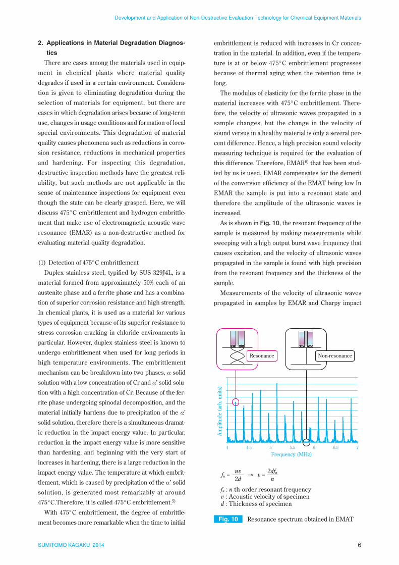
As is shown in Fig. 10, the resonant frequency of the
sample is measured by making measurements while
sweeping with a high output burst wave frequency that
causes excitation, and the velocity of ultrasonic waves
propagated in the sample is found with high precision
from the resonant frequency and the thickness of the
sample.
Measurements of the velocity of ultrasonic waves
propagated in samples by EMAR and Charpy impact
2. Applications in Material Degradation Diagnos-
tics
There are cases among the materials used in equip-
ment in chemical plants where material quality
degrades if used in a certain environment. Considera-
tion is given to eliminating degradation during the
selection of materials for equipment, but there are
cases in which degradation arises because of long-term
use, changes in usage conditions and formation of local
special environments. This degradation of material
quality causes phenomena such as reductions in corro-
sion resistance, reductions in mechanical properties
and hardening. For inspecting this degradation,
destructive inspection methods have the greatest reli-
ability, but such methods are not applicable in the
sense of maintenance inspections for equipment even
though the state can be clearly grasped. Here, we will
discuss 475°C embrittlement and hydrogen embrittle-
ment that make use of electromagnetic acoustic wave
resonance (EMAR) as a non-destructive method for
evaluating material quality degradation.
(1) Detection of 475°C embrittlement
Duplex stainless steel, typified by SUS 329J4L, is a
material formed from approximately 50% each of an
austenite phase and a ferrite phase and has a combina-
tion of superior corrosion resistance and high strength.
In chemical plants, it is used as a material for various
types of equipment because of its superior resistance to
stress corrosion cracking in chloride environments in
particular. However, duplex stainless steel is known to
undergo embrittlement when used for long periods in
high temperature environments. The embrittlement
mechanism can be breakdown into two phases, α solid
solution with a low concentration of Cr and α’ solid solu-
tion with a high concentration of Cr. Because of the fer-
rite phase undergoing spinodal decomposition, and the
material initially hardens due to precipitation of the α’
solid solution, therefore there is a simultaneous dramat-
ic reduction in the impact energy value. In particular,
reduction in the impact energy value is more sensitive
than hardening, and beginning with the very start of
increases in hardening, there is a large reduction in the
impact energy value. The temperature at which embrit-
tlement, which is caused by precipitation of the α’ solid
solution, is generated most remarkably at around
475°C.Therefore, it is called 475°C embrittlement.5)
With 475°C embrittlement, the degree of embrittle-
ment becomes more remarkable when the time to initial Fig. 10 Resonance spectrum obtained in EMAT
Frequency (MHz)
4 4.5 5 5.5 6 6.5 7
Am
plit
ud
e (a
rb. u
nit
s)
Resonance Non-resonance
fn =
fn : n-th-order resonant frequencyv : Acoustic velocity of specimend : Thickness of specimen
v =→2dnv
n2dfn

7SUMITOMO KAGAKU 2014
Development and Application of Non-Destructive Evaluation Technology for Chemical Equipment Materials
normal deformation rates is small, but with rapid defor-
mation as in Charpy impact tests, embrittlement mani-
fests itself even at hydrogen concentrations of 100 ppm
or less.
In terms of hydrogen storage, caution is naturally nec-
essary in cases when process fluids contain hydrogen,
but when the anticorrosion properties of titanium are
not required on the shell side, titanium materials are
mostly not used in baffle plates and tube plates that sup-
port the heat transfer tubes. Caution is necessary
because there are examples of hydrogen that is gener-
ated by minute amounts of corrosion in these members
being stored in the heat transfer tubes.
Since hydrogen embrittlement of titanium is caused
by the formation of brittle needle shaped hydrides
which can appear through changes in the material
properties such as electrical conductivity, modulus of
elasticity and hardness. The changes in these various
properties can be detected in terms of changes in the
velocity of longitudinal waves and transverse waves of
ultrasonic waves propagated in samples. The relation-
ship between the average velocity and the changes in
electrical conductivity is shown in Fig. 13. EMAR is
effective for the measurement of the velocity of sound
waves propagated in samples. However, with minute
amounts of hydrogen storage of 1000 ppm or less, the
amount of changes in these parameters is extremely
small and therefore clear determinations are difficult if
there is a variation in the measurement data. Thus, we
focused on the factors for hydrides inhibiting ultrasonic
wave propagation and developed a method for detect-
ing hydrogen embrittlement by measuring the attenu-
ation rate of ultrasonic waves excited for a specific res-
onant frequency by the EMAT.7) Fig. 14 shows the
tests were conducted with SUS 329J4L material in
which 475°C embrittlement had been generated artifi-
cially by adjusting heating temperature and heating
time in an electric furnace. Fig. 11 gives results show-
ing the relationship between the average value of the
velocity of longitudinal and transverse waves of the
ultrasonic waves propagated in the samples shown in
the horizontal axis and the Charpy impact value at
room temperature (25°C) shown in the vertical axis.
Along with the material becoming embrittled and the
Charpy impact value being reduced because of the
475°C embrittlement, the average velocity for the lon-
gitudinal waves and transverse waves of the ultrasonic
waves propagated in the sample becomes slower. The
change in the velocity of the ultrasonic waves propagat-
ed in the sample is small at 1% for the large reduction
by embrittlement in the impact energy value to about
1/8 of that for sound parts, but EMAR can evaluate
minute changes in sound velocity with high precision;
therefore, this evaluation curve is used to evaluate the
presence or absence of 475°C embrittlement and the
degree of the embrittlement in duplex stainless steel.
(2) Detection of hydrogen embrittlement
Titanium has superior corrosion resistance in a sea
water environment. In Sumitomo Chemical, sea water
is often used in the heat exchangers. However, the affin-
ity of titanium to hydrogen is high and therefore the
needle shaped hydrides like those shown in Fig. 12
form within the metal and embrittlement occurs when
the hydrogen is stored. As a result, reduction in ductility
is caused without evidence of corrosion and therefore
the reduction in thickness occurs. Typically, if the
hydrogen concentration in titanium is roughly 500 ppm
or less, the reduction in mechanical characteristics at
Fig. 11 Correlation between Average velocity and Charpy impact value
0
10
20
30
40
50
60
70
80
90
4090 4100 4110 4120 4130 4140 4150 4160
Average velocity (m/s)(longitudinal and shear waves)
Ch
arpy
impa
ct v
alu
e (J
/cm
2 )
Fig. 12 Microstructure of titanium affected by hydrogen embrittlement
200 μm

8SUMITOMO KAGAKU 2014
Development and Application of Non-Destructive Evaluation Technology for Chemical Equipment Materials
results of comparing attenuation rates of ultrasonic
energy at 5.2 MHz, which is the fifth resonant frequen-
cy, for a healthy titanium sample and hydrogen stored
titanium sample with hydrogen stored at approximately
300 ppm. With the healthy material, 1400 µsec were
required for attenuation of energy to 20%, but in the
hydrogen stored brittle material the attenuation
occurred in 220 µsec. Hence, it can be concluded that
detection of hydrogen storage is possible even for a
minute hydrogen embrittlement by measuring the time
a resonant state which can be maintained in this man-
ner. However, this method is a partial inspection
method that identifies inspection sites; therefore, when
sites for hydrogen embrittlement cannot be identified
in the direction of the tube axis in heat transfer tubes
and other pipes, multipoint inspections must be carried
out by determining a pitch to move in the axial direc-
tion. Since there is an overwhelming number of heat
transfer tubes which are the objects of this inspection,
a problem for the future is putting together a method
that can carry out continuous inspections over the
entire length of heat transfer tubes.
3. Applications in Corrosion Inspections for Con-
tact Parts in Pipe Framing
As shown in Fig. 15 water from rain and other
sources can easily accumulate at the contact parts in
pipe framing, and coatings at the contact parts with the
frame can easily peel off because of thermal expansion
and contraction of the pipes. Therefore recoating and
other maintenance are difficult at these sites where
external corrosion can easily occur and progress.
On the other hand, the number of frames is propor-
tional to the layout length of the pipes and is therefore
immense. While corrosion and thinning are important
inspection points, a large amount of time is required
even for primary inspections centered on visual inspec-
tions. In addition, secondary inspections are carried out
using non-destructive inspection methods such as ultra-
sonic tests at sites that are problematic during primary
inspections, but incidental construction, such as removal
of coatings on the surface of pipes, scraping of rust and
surface polishing are required for carrying out ultrason-
ic inspection. While the progression of corrosion and
thinning will make a dangerous situation for safety con-
cerns, and also there is one more concern that the
inspections will not be carried out in time. Thus, we car-
ried out development of corrosion inspection techniques
for the contact parts of pipe framing using the charac-
teristic features of the electromagnetic acoustic wave
technique that can excite ultrasonic waves without con-
tact. EMAT has been developed not only to reduce the
time required for secondary inspections by simplifying
the pretreatment of sites to be inspected, but also con-
sideration is given to the desire to increase the reliability
of the contact parts of pipe framing. Here, we will
describe the current state of the investigation into these
techniques.
Fig. 13 Changes in ultrasonic velocity (left) and conductivity (right) due to hydrogen embrittlement
5800
5900
6000
6100
6200
6300
3000
3050
3100
3150
3200
3250
0 500 1000 1500 2000 2500
Lon
gitu
din
al wave velocity (m
/s)
Sh
ear
wav
e ve
loci
ty (
m/s
)
Hydrogen storage capacity (ppm)
3.48
3.49
3.50
3.51
3.52
3.53
3.54
3.55
0 500 1000 1500 2000 2500
Con
du
ctiv
ity
(IA
CS
%)
Hydrogen storage capacity (ppm)
Shear waveLongitudinal wave
Fig. 14 Attenuation of ultrasonic energy in titanium
0
0.1
0.2
0.3
0.4
0.5
0.6
0.7
0.8
0.9
1
0 200 400 600 800 1000 1200 1400 1600
Ult
raso
nic
en
erg
y (a
rb. u
nit
s)
Time (μs)
Before Hydrogen embrittlement
After Hydrogen embrittlement

9SUMITOMO KAGAKU 2014
Development and Application of Non-Destructive Evaluation Technology for Chemical Equipment Materials
without any contact. However, the energy conversion
efficiency of EMAT is lower than that of piezoelectric
probes. Therefore, the most important problem is exci-
tation of ultrasonic waves with a superior S/N ratio
which has the intensity required for measurements in
the targeted objects. First of all, in terms of improve-
ments related to devices, a wideband preamplifier was
used for a wideband sweep of frequencies in EMAR
used for degradation diagnostics in materials, but to nar-
row down the frequency band for exciting ultrasonic
waves without resonance at flaws, therefore a narrow
band preamplifier that only amplifies the signal in that
particular band had been introduced. In addition, a
bypass capacitor was put in place to eliminate high-fre-
quency noise in the signal. In terms of the EMAT, a
thick wire was used in the coil to increase the input volt-
age value, and in addition to that a variety of investiga-
tions had been carried out such as reassessing and opti-
mizing the magnet arrangement. Fig. 17 shows the
waveform of ultrasound during exciting and receiving
with 60.5 mm outside diameter, 3.9 mm thick pipe as
the target. Even if the distance between the probes was
set at 50 cm or greater, envisioning the width of framing,
exciting and receiving the signal required for the meas-
urement could be possible. In the next step, we targeted
improvements in measurement precision for the depth
of reduced thickness in addition to current measure-
ments for pipes with simulated reduced thickness and
corroded pipes in actual equipment. Fig. 18 shows an
example of a measurement on a corroded pipe with an
outside diameter of 60.5 mm and thickness of 3.9 mm
in actual equipment. We can see that the arrival time for
the ultrasonic waves is delayed in the part with reduced
thickness over that in the healthy part, and the ampli-
tude is attenuated. The depth of the reduction in thick-
ness estimated from the delay in arrival time is 1.6 mm,
The inspection technique forming the basis of this is
the surface wave method for ultrasonic testing shown
in Fig. 16.8) The surface wave method of ultrasonic test-
ing is carried out by setting up probes, which sandwich
a framing part, for exciting and receiving the surface
waves.
When the thickness of a pipe is reduced the arrival
time of the surface wave is delayed by passing the part
where the pipe is thinned out, and the amount of reduc-
tion in thickness is estimated from the time delay. Unlike
the ultrasonic attenuation method, removal of liquids is
unnecessary because the fluid inside has negligible
effect on the time delay. The merit of this method is that
when corrosion exists the amount of reduction in thick-
ness is measured from the elongation of the propagation
distance of the surface waves rather than a relative value
such as attenuation. However, demerits are that surface
treatment of parts where a probe is set up is necessary
and the probe must be strongly pressed against the sur-
face of the pipe to make a sizable inspection jig neces-
sary.
It is important to resolve these demerits with the con-
ventional surface wave method of ultrasonic testing.
Hence, we decided to investigate using the EMAT
which can excite ultrasonic waves within the material
Fig. 15 Acceleration of external corrosion of pipe on a pipe support
Coating deterioration
Acceleration of external corrosion
Accumulation of water
Fig. 16 Surface wave technique of ultrasonic testing
Surface wave
Transmitter Receiver
Fig. 17 Waveform of ultrasound in a non-defective steel pipe
Ultrasound signal
Time (μs)
Am
plit
ud
e (a
rb. u
nit
s)
10SUMITOMO KAGAKU 2014
Development and Application of Non-Destructive Evaluation Technology for Chemical Equipment Materials
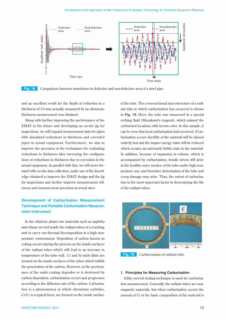
of the tube. The cross-sectional microstructure of a radi-
ant tube in which carburization has occurred is shown
in Fig. 19. Here, the tube was immersed in a special
etching fluid (Murakami’s reagent), which stained the
carburized locations with brown color. In this sample, it
can be seen that local carburization had occurred. If car-
burization occurs ductility of the material will be almost
entirely lost and the impact energy value will be reduced
which creates an extremely brittle state in the material.
In addition, because of expansion in volume, which is
accompanied by carburization, tensile stress will arise
in the healthy outer surface of the tube under high tem-
perature use, and therefore deformation of the tube and
creep damage may arise. Thus, the extent of carburiza-
tion is the most important factor in determining the life
of the radiant tubes.
1. Principles for Measuring Carburization
Eddy current testing technique is used for carburiza-
tion measurement. Generally the radiant tubes are non-
magnetic materials, but when carburization occurs the
amount of Cr in the basic composition of the material is
and an excellent result for the depth of reduction in a
thickness of 2.0 mm actually measured by an ultrasonic
thickness measurement was obtained.
Along with further improving the performance of the
EMAT in the future and developing an on-site jig for
inspections, we will expand measurement data for pipes
with simulated reductions in thickness and corroded
pipes in actual equipment. Furthermore, we aim to
improve the precision of the techniques for evaluating
reductions in thickness after surveying the configura-
tions of reductions in thickness due to corrosion in the
actual equipment. In parallel with this, we will move for-
ward with on-site data collection, make use of the knowl-
edge obtained to improve the EMAT design and the jig
for inspections and further improve measurement effi-
ciency and measurement precision at actual sites.
Development of Carburization Measurement
Technique and Portable Carburization Measure-
ment Instrument
In the ethylene plants raw materials such as naphtha
and ethane are fed inside the radiant tubes of a cracking
unit to carry out thermal decomposition at a high tem-
perature environment. Deposition of carbon known as
coking occurs during the process on the inside surfaces
of the radiant tubes which will lead to an increase in
temperature of the tube wall . Cr and Si oxide films are
formed on the inside surfaces of the tubes which inhibit
the penetration of the carbon. However, as the perform-
ance of the oxide coating degrades or is destroyed by
carbon deposition, carburization occurs and progresses
according to the diffusion rate of the carbon. Carburiza-
tion is a phenomenon in which chromium carbides,
Cr7C3 is a typical form, are formed on the inside surface
Fig. 18 Comparison between waveforms in defective and non-defective area of a steel pipe
Time (μs)
Time delay
Am
plit
ud
e at
ten
uat
ion
Am
plit
ud
e (a
rb. u
nit
s)
Defectivearea
Non-defectivearea
Defectivearea
Non-defectivearea
Fig. 19 Carburization of radiant tube

11SUMITOMO KAGAKU 2014
Development and Application of Non-Destructive Evaluation Technology for Chemical Equipment Materials
ever, in radiant tubes made up of HP alloys (25% Cr –
35% Ni) and 45% Ni alloys that have been used in recent
years, chrome deficient layers will arise because of the
oxidation that occurs on the outside surface of the tubes
with use at high temperatures. Similarly, these parts will
become ferromagnetic in the same manner as described
above in case of carburization. Therefore, the eddy cur-
rent generated on the outer surface will not be able to
permeate through the thickness because of the skin
effect, and hence carburization measurements are not
possible with the eddy current testing technique.
With regard to this problem, at Sumitomo Chemical,
after integrating a permanent magnet into the probe and
reducing the effects of the magnetic layer of the outer
surface layer part by magnetizing the part, we are meas-
uring the thickness of the non-carburized layer using
the carburization evaluation curve that calibrates the
relationship between the phase angle of the signal
obtained and the thickness of the non-carburized part.
However, in this case, in terms of the measurement pre-
cision of this method the effects are shown in Fig. 22
with the evaluation values for non-carburized layer thick-
ness on the horizontal axis and actual measurement val-
ues for non-carburized layer thickness on the vertical
axis. The actual measured values are within a range
of ±1 mm from the evaluation values, and hence carbur-
ization measurements could be carried out with high
precision.
2. Handling of Nitride Layers
Resistance to carburization can be increased if the
radiant tube material is upgraded to 45% Ni alloy and
this makes long-term use possible, but a layer (called
nitridation layer in the following) made up of a com-
reduced and the balance of components changes due to
the formation of Cr7C3 chromium carbides. Therefore,
those parts in which carburization occur will be convert-
ed into ferromagnetic materials.
As is shown in Fig. 20, if a coil in which an alternating
current flows is brought close to the outer surface of a
radiant tube, an eddy current is generated in the direc-
tion of thickness of the radiant tube by the phenomenon
of electromagnetic induction. Furthermore, the space
between the carburized layer (ferromagnetic) and the
coil is measured, in other words the non-ferromagnetic
layer thickness is directly measured by this technique.
Specifically, the thickness of the non-carburized layer is
reduced as the carburization progresses in the direction
of thickness. This change can be detected as a change
in phase angle, which is one evaluation parameter, of
the eddy current testing output signal. Therefore, the
carburization evaluation curve, which is a calibration of
the relationship between phase angle and the non-car-
burized layer thickness as shown in Fig. 21, is used to
evaluate the thickness of the non-carburized layer. How-
Fig. 21 Calibration curve for carburization measurement
Sou
nd
laye
rth
ick
nes
s (m
m)
Phase angle (degree)Small Large
Thick
Thin
Fig. 20 Principle of carburization measurement
Chromium depleted layer(Ferromagnetic material)
Sound Layer(Non-magnetic material)
Carburization layer(Ferromagnetic material)
CoilPermanent magnet
Fig. 22 Carburization measurement accuracy in 45% Ni alloy
0
2
4
6
8
10
12
14
0 2 4 6 8 10 12 14
Act
ual
mea
sure
men
t va
lue
(mm
)
Evaluation value (mm)

12SUMITOMO KAGAKU 2014
Development and Application of Non-Destructive Evaluation Technology for Chemical Equipment Materials
pound (Cr2N) of nitrogen and chromium is formed in
air as shown in Fig. 23 on the inside of an oxide layer
on the outer surface of the tubes when they are used
for a long time at high temperatures. If the nitridation
layer progresses approximately 1 – 2 mm, a layer with
the same magnetic properties as with carburization is
formed on the outer surface. The changes in electro-
magnetic properties with the formation of this thick
nitridation layer are large and the precision of carbur-
ization measurements will be reduced. Specifically, non-
carburized parts are also erroneously diagnosed as hav-
ing occurrences of carburization and the thickness of
the carburization is overestimated.
We can consider a method in which a strong magnetic
field is applied from the outside and magnetic saturation
created in the same manner as with magnetic layers due
to oxidation of the outside surface of the tubes, but if
magnetization is carried out to the extent that reduces
the effects of the thick nitridation layer, the evaluation
of the carburized layer progressing from the inside sur-
face of the radiant tube is also affected. Therefore, we
investigated the method for evaluating the presence or
absence of a nitridation layer from the changes in the
properties of an eddy current signal due to the nitrida-
tion layer on the outside tubes. Using the radiant tube
samples from the actual equipment, we measured the
carburization of the samples and also carried out cross-
sectional structure observations to evaluate the absence
or presence of nitridation and carburization.
Fig. 24 adds the results of cross-sectional structure
observations to results showing the phase angle for
eddy current test data for the samples on the horizontal
Fig. 23 Nitridation of radiant tube (outer surface)
50.0 μm
axis and amplitude on the vertical axis. There is an
increase in both the phase angle and amplitude of the
eddy current signal at carburized parts over the healthy
parts, but at the nitrided parts only the phase angle
increases and no changes are observed in the ampli-
tude. In addition, when nitridation and carburization are
combined the intermediate characteristics are displayed.
Based on these results, we developed a method9) for
dividing and determining carburization, nitridation, com-
bined nitridation and carburization regions by solid line
A-B and dashed line C-D as shown in Fig. 25.
In addition, with regard to the problem of overesti-
mation of carburization thickness because of the com-
bination of nitridation and carburization, we came to
understand that there is an approximately 2 mm over-
estimation of the actual carburization thickness if
nitridation and carburization are combined as a result
of investigations based on the results of carburization
Fig. 24 Correlation between amplitude and phase angle
Am
plit
ud
e (V
)
Nitridation
Carburization
Nitridation+
Carburization
Sound
Phase angle (degree)Small Large
Large
Small
Fig. 25 Determination procedure of nitridation layer
Am
plit
ud
e (V
)
Nitridation
Carburization Nitridation+
Carburization
Sound
Phase angle (degree)Small Large
Large
Small A
B
C D

13SUMITOMO KAGAKU 2014
Development and Application of Non-Destructive Evaluation Technology for Chemical Equipment Materials
is reached approximately 1 minute after starting up the
software for carburization measurements by carrying
out a simple calibration using the standard test piece.
The presence or absence of a nitridation layer and the
depth of carburization are displayed on the screen just
by bringing the probe into contact with the surface of
the radiant tube. Storage of measurement data is also
simple, and in the continuous measurement mode, the
carburization measurement data is continuously stored
in the PC, and at the same time, the maximum carbur-
ization measurement value is displayed on the screen.
Since the instrumentation is lightweight, compact
and battery-powered, it does not require a power sup-
ply to be assured inside the furnace, and since the
equipment is easily carried around, the efficiency of on-
site operations is greatly improved. In addition, we are
able to reduce the immense time required for data
analysis to almost zero. Moreover, we also prepared an
English version of the software in which all of the text
on the screen is in English to handle use in overseas
plants.
measurements and cross-sectional structure observa-
tions in the samples. Therefore, when a combination
of nitridation and carburization is determined, 2 mm
is subtracted from the measurement value of the car-
burization thickness in order to estimate the actual
carburization thickness. Moreover, we will improve
the reliability of data by conducting destructive inves-
tigations on the samples in the future.
3. Development and Application of Portable Car-
burization Measurement Instrument
With the Sumitomo Chemical carburization measure-
ment technique, carburization thickness can be evaluat-
ed with high precision while considering the effects of
nitridation. However, even though the eddy current test-
ing equipment, data recorders, etc., for carburization
measurements have become smaller and lighter in
weight, it cannot be said that they can be easily taken
inside cracking furnaces for inspections. In addition, cal-
ibration of equipment, and analysis of data obtained are
special techniques requiring adequate knowledge, and
measurements by certified eddy current testing person-
nel is necessary.
In Sumitomo Chemical plants in Japan it has been pos-
sible to have inspections carried out by certified person-
nel, but at affiliated overseas companies, starting with
the Middle East, it is difficult to carry out inspections at
the same level. Therefore, we developed portable car-
burization measuring instrumentation that combines a
lightweight, compact and robust measurement instru-
ment body and a tablet PC on which a software version
of the data analysis know-how is installed. In addition to
assuring measurement precision by this means, meas-
urement technology that improves operability at the
actual site and does not require knowledge of specialists
can be provided.
Fig. 26 shows the configuration of the portable car-
burization measuring instrumentation.
The instrumentation is made up of the carburization
measurement device a tablet PC, a carburization meas-
urement probe, a probe connector, a USB cable and a
standard test piece. The size of the carburization meas-
urement device is 110 mm (W)×210mm (L)×24mm (H),
with a weight of 480 g (including AA nickel metal-
hydride batteries), and five hours of continuous meas-
urements are possible.
Fig. 27 shows the tablet screen during a carburiza-
tion measurement. A state in which it is possible to
carry out carburization measurements on radiant tubes
Fig. 26 Portable carburization measuring instrument
Probe coil
ConnectorStandard test piece
Carburization measurement instrument body
Tablet type PC
Fig. 27 Screenshot of portable carburization measuring instrument
Carburization layer thickness

14SUMITOMO KAGAKU 2014
Development and Application of Non-Destructive Evaluation Technology for Chemical Equipment Materials
Sumitomo Chemical, but also plant operations without
accidents and without disasters are our minimum
responsibility as a corporation to the regions and soci-
eties with which we coexist. To carry out a suitable
maintenance at suitable timings for facilities that will be
aging even more in the future will become an even
greater responsibility for those of us in the field of facil-
ity maintenance. Starting with the techniques that are
introduced in this article, we truly want to develop and
investigate the maintenance techniques that will be even
more necessary in the future and contribute to the con-
tinuing safety and stable operation of plants.
References
1) Sumitomo Chemical Co., Ltd., Jpn. Tokkyo Koho
5169983 (2013).
2) Sumitomo Chemical Co., Ltd., Jpn. Tokkyo Koho
5233835 (2013).
3) Sumitomo Chemical Co., Ltd., Jpn. Kokai Tokkyo
Koho 2014-52265 (2014).
4) Sumitomo Chemical Co., Ltd., Jpn. Tokkyo Koho
5417979 (2013).
5) D. Chandra and L. H. Schwartz, Metall. Trans., 2,
511 (1971).
6) H. Ogi, H. Ledbetter, S. Kim and M. Hirao, J. Acoust.
Soc. Am., 106, 660 (1999).
7) Sumitomo Chemical Co., Ltd., Jpn. patent applica-
tion no 2013-171335 (2013).
8) N. Hirota, E. Kishi, Y. Yokono, T. Imanaka and M.
Yotsutsuji, J. JSNDI, 50, 368 (2001).
9) Sumitomo Chemical Co., Ltd., Jpn. Tokkyo Koho
3765188 (2006).
Summary
In this article we have introduced inspection and diag-
nostic techniques developed with low cost, high speed,
high quality as keywords. Magnetic eddy current flaw
testing in heat transfer tubes made of magnetic materi-
als, such as nickel and duplex stainless steel, has
reached the same level of inspection quality as eddy cur-
rent flaw testing in nonmagnetic material pipes. In addi-
tion, even with reactor tubes made of ferromagnetic
materials such as carbon steel, it has become possible
to detect and evaluate local reductions in thickness such
as those which exist below the baffle plates. Above all,
this method is being applied as a high-speed inspection
technique and can be an alternative to IRIS. EMAR can
evaluate the thermal aging embrittlement of duplex
stainless steel and hydrogen embrittlement of titanium.
In addition, making the characteristic ability to excite
ultrasonic waves without contacting the target material,
we are moving forward with development of a corrosion
inspection technique on the contact parts of pipe fram-
ing. By application of eddy current for the carburization
measurement, it has become possible to evaluate car-
burization depth with high precision including evalua-
tions of nitridation layers which has been accompanied
by long-term use. Furthermore, we have developed a
portable carburization measuring instrumentation that
improves operability in the actual field, and does not
require a specialist to operate it. The portable instru-
ment has been in use for measuring carburization depth
at our plants both in Japan and overseas.
Continuation of plant safety and stable operations are
not only assuring stable and continuous earnings for

15SUMITOMO KAGAKU 2014
Development and Application of Non-Destructive Evaluation Technology for Chemical Equipment Materials
P R O F I L E
Hidehiko SUETSUGU
Sumitomo Chemical Co., Ltd.Production & Safety Fundamental Technology CenterSenior Research Associate
Tatsuya KUSUMOTO
Sumitomo Chemical Co., Ltd.Production & Safety Fundamental Technology CenterResearcher
Toyokazu TADA
Sumitomo Chemical Co., Ltd.Production & Safety Fundamental Technology CenterResearch Associate