developing technologies for upcycling associated gas
TRANSCRIPT
Upcycling Associated Gas into Higher-Value Products
Developing Technologies for
CONTENTSBACKGROUND • • • • • • • • • • • • • • • • • • • • • • • • • • • • • • • • • • • • • • • • • • • • • • • • • • • • • • • • • • • • • • • • • • • • • • • • • • • • • • • • • • • • • • • • • • • • • • • • • • • • • • • • • • • • • • • • • • • • • • • • • • • • • • • • • • • 1
INTRODUCTION• • • • • • • • • • • • • • • • • • • • • • • • • • • • • • • • • • • • • • • • • • • • • • • • • • • • • • • • • • • • • • • • • • • • • • • • • • • • • • • • • • • • • • • • • • • • • • • • • • • • • • • • • • • • • • • • • • • • • • • • • • • • • • • • • • 2A Wasted Natural Resource • • • • • • • • • • • • • • • • • • • • • • • • • • • • • • • • • • • • • • • • • • • • • • • • • • • • • • • • • • • • • • • • • • • • • • • • • • • • • • • • • • • • • • • • • • • • • • • • • • • • • • • • • • • • • • • • • • • • • • • • • • • • • • • • • • • • • • • • • • • • • • • • • • • • •2The Environmental Impact of Natural Gas Flaring • • • • • • • • • • • • • • • • • • • • • • • • • • • • • • • • • • • • • • • • • • • • • • • • • • • • • • • • • • • • • • • • • • • • • • • • • • • • • • • • • • • • • • • • • • • • • • • • • • • • • • • • • • • • • • • • • • • • •3DOE Research and Development (R&D) to Mitigate Flaring • • • • • • • • • • • • • • • • • • • • • • • • • • • • • • • • • • • • • • • • • • • • • • • • • • • • • • • • • • • • • • • • • • • • • • • • • • • • • • • • • • • • • • • • • • • • • • • • • • • • • • • •4
OVERVIEW OF EXTRAMURAL PROJECTS • • • • • • • • • • • • • • • • • • • • • • • • • • • • • • • • • • • • • • • • • • • • • • • • • • • • • • • • • • • • • • • • • • • • • • • • • • • • • • • • • • • • • • • • • • • • • 4Modular System for Direct Conversion of Methane into Methanol via Photocatalysis • • • • • • • • • • • • • • • • • • • • • • • • • • • • • • • • • • • • • • • • • • • • • • • • • • • • • • • • • • • • • • • • • • • • • • • • • • • • • • • • • 5
Electrocatalytically Upgrading Methane to Benzene in a Highly Compacted Microchannel Protonic Ceramic Membrane Reactor • • • • • • • • • • • • • • • • • • • • • • • • • • • 7
Core-Shell Oxidative Aromatization Catalysts for Single Step Liquefaction of Distributed Shale Gas • • • • • • • • • • • • • • • • • • • • • • • • • • • • • • • • • • • • • • • • • • • • • • • • • • • • • • • • • • • • • • 9
Isolated Single Metal Atoms Supported on Silica for One-Step Non-Oxidative Methane Upgrading to Hydrogen and Value-Added Hydrocarbons • • • • • 11
Process Intensification by One-Step, Plasma-Assisted Catalytic Synthesis of Liquid Chemicals from Light Hydrocarbons • • • • • • • • • • • • • • • • • • • • • • • • • • • • • • • • • 13
Methane Partial Oxidation over Multifunctional 2-D Materials • • • • • • • • • • • • • • • • • • • • • • • • • • • • • • • • • • • • • • • • • • • • • • • • • • • • • • • • • • • • • • • • • • • • • • • • • • • • • • • • • • • • • • • • • • • • • • • • • • • • • • • • • • • 14
Gas to Carbon Fiber Crystals (G2-CFX) • • • • • • • • • • • • • • • • • • • • • • • • • • • • • • • • • • • • • • • • • • • • • • • • • • • • • • • • • • • • • • • • • • • • • • • • • • • • • • • • • • • • • • • • • • • • • • • • • • • • • • • • • • • • • • • • • • • • • • • • • • • • • • • • • • • • • • • 16
Modular Processing of Flare Gas for Carbon Nanoproducts • • • • • • • • • • • • • • • • • • • • • • • • • • • • • • • • • • • • • • • • • • • • • • • • • • • • • • • • • • • • • • • • • • • • • • • • • • • • • • • • • • • • • • • • • • • • • • • • • • • • • • • • • • • • • • 18
Microwave Catalysis for Process Intensified Modular Production of Carbon Nanomaterials from Natural Gas • • • • • • • • • • • • • • • • • • • • • • • • • • • • • • • • • • • • • • • • • • • • • • • • • 19
OVERVIEW OF NETL FIELD WORK PROPOSAL (FWP) PROJECTS • • • • • • • • • • • • • • • • • • • • • • • • • • • • • • • • • • • • • • • • • • • • • • • • • • • • • • • • • • • 21Electrochemical Upgrading of Flare Gas • • • • • • • • • • • • • • • • • • • • • • • • • • • • • • • • • • • • • • • • • • • • • • • • • • • • • • • • • • • • • • • • • • • • • • • • • • • • • • • • • • • • • • • • • • • • • • • • • • • • • • • • • • • • • • • • • • • • • • • • • • • • • • • • • • • • • 22
Production of Hydrogen and Carbon from Catalytic Flare Gas Pyrolysis • • • • • • • • • • • • • • • • • • • • • • • • • • • • • • • • • • • • • • • • • • • • • • • • • • • • • • • • • • • • • • • • • • • • • • • • • • • • • • • • • • • • • • • • • • • • • • • 23
Commercialization Study of NETL Technology for Flare Gas to Olefins and Liquids • • • • • • • • • • • • • • • • • • • • • • • • • • • • • • • • • • • • • • • • • • • • • • • • • • • • • • • • • • • • • • • • • • • • • • • • • • • • • • • • • 24
Microwave Enhanced Flare Gas Conversion to Value-Added Chemicals • • • • • • • • • • • • • • • • • • • • • • • • • • • • • • • • • • • • • • • • • • • • • • • • • • • • • • • • • • • • • • • • • • • • • • • • • • • • • • • • • • • • • • • • • • • • • • • 25
NEXT STEPS • • • • • • • • • • • • • • • • • • • • • • • • • • • • • • • • • • • • • • • • • • • • • • • • • • • • • • • • • • • • • • • • • • • • • • • • • • • • • • • • • • • • • • • • • • • • • • • • • • • • • • • • • • • • • • • • • • • • • • • • • • • • • • • • • • • 26
APPENDIX: • • • • • • • • • • • • • • • • • • • • • • • • • • • • • • • • • • • • • • • • • • • • • • • • • • • • • • • • • • • • • • • • • • • • • • • • • • • • • • • • • • • • • • • • • • • • • • • • • • • • • • • • • • • • • • • • • • • • • • • • • • • • • • • • • • • • • 27Associated Gas Flaring Factsheet: 2018 BAKKEN • • • • • • • • • • • • • • • • • • • • • • • • • • • • • • • • • • • • • • • • • • • • • • • • • • • • • • • • • • • • • • • • • • • • • • • • • • • • • • • • • • • • • • • • • • • • • • • • • • • • • • • • • • • • • • • • • • • • • • • • • • 27
Associated Gas Flaring Factsheet: 2018 PERMIAN • • • • • • • • • • • • • • • • • • • • • • • • • • • • • • • • • • • • • • • • • • • • • • • • • • • • • • • • • • • • • • • • • • • • • • • • • • • • • • • • • • • • • • • • • • • • • • • • • • • • • • • • • • • • • • • • • • • • • • • • • 28
Associated Gas Flaring Factsheet: 2018 EAGLE FORD• • • • • • • • • • • • • • • • • • • • • • • • • • • • • • • • • • • • • • • • • • • • • • • • • • • • • • • • • • • • • • • • • • • • • • • • • • • • • • • • • • • • • • • • • • • • • • • • • • • • • • • • • • • • • • • • • • • • • 29
WWW.NETL.DOE.GOV
1DEVELOPING TECHNOLOGIES FOR UPCYCLING ASSOCIATED GAS INTO HIGHER-VALUE PRODUCTS
BACKGROUND
1. Wang, Zhongmin, and Alan J. Krupnick. “US Shale Gas Development: What Led to the Boom?” Washington, DC: Resources for the Future, May 2013, https://media.rff.org/archive/files/sharepoint/WorkImages
2. U.S. Energy Information Administration, “Natural gas venting and flaring increased in North Dakota and Texas in 2018”, December 2019, https://www.eia.gov/todayinenergy/detail.php?id=42195#
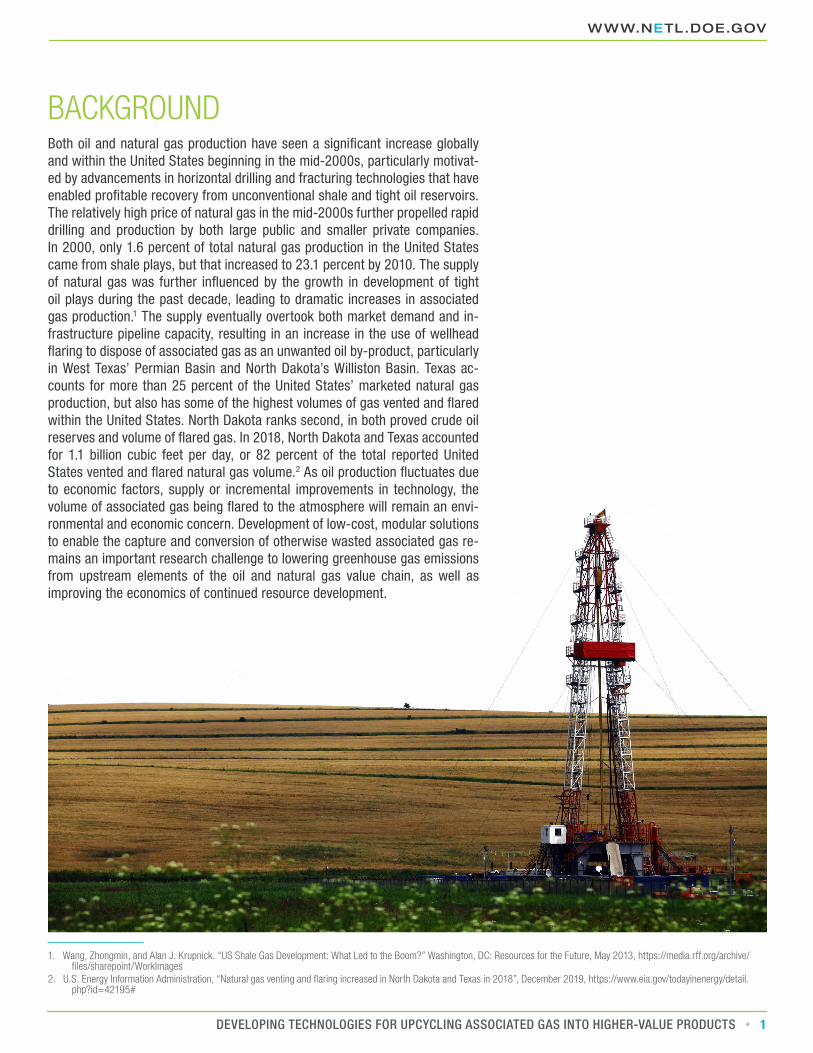
Both oil and natural gas production have seen a significant increase globally and within the United States beginning in the mid-2000s, particularly motivat-ed by advancements in horizontal drilling and fracturing technologies that have enabled profitable recovery from unconventional shale and tight oil reservoirs. The relatively high price of natural gas in the mid-2000s further propelled rapid drilling and production by both large public and smaller private companies. In 2000, only 1.6 percent of total natural gas production in the United States came from shale plays, but that increased to 23.1 percent by 2010. The supply of natural gas was further influenced by the growth in development of tight oil plays during the past decade, leading to dramatic increases in associated gas production.1 The supply eventually overtook both market demand and in-frastructure pipeline capacity, resulting in an increase in the use of wellhead flaring to dispose of associated gas as an unwanted oil by-product, particularly in West Texas’ Permian Basin and North Dakota’s Williston Basin. Texas ac-counts for more than 25 percent of the United States’ marketed natural gas production, but also has some of the highest volumes of gas vented and flared within the United States. North Dakota ranks second, in both proved crude oil reserves and volume of flared gas. In 2018, North Dakota and Texas accounted for 1.1 billion cubic feet per day, or 82 percent of the total reported United States vented and flared natural gas volume.2 As oil production fluctuates due to economic factors, supply or incremental improvements in technology, the volume of associated gas being flared to the atmosphere will remain an envi-ronmental and economic concern. Development of low-cost, modular solutions to enable the capture and conversion of otherwise wasted associated gas re-mains an important research challenge to lowering greenhouse gas emissions from upstream elements of the oil and natural gas value chain, as well as improving the economics of continued resource development.
NATIONAL ENERGY TECHNOLOGY LABORATORY
2 DEVELOPING TECHNOLOGIES FOR UPCYCLING ASSOCIATED GAS INTO HIGHER-VALUE PRODUCTS
INTRODUCTIONA Wasted Natural Resource
3. U.S. Energy Information Administration, “Natural Gas Gross Withdrawals and Production”, July 2020, https://www.eia.gov/dnav/ng/ng_prod_sum_a_EPG0_VGV_mmcf_a.htm4. U.S. Energy Information Administration, “United States Natural Gas Industrial Price”, July 2020, https://www.eia.gov/dnav/ng/hist/n3035us3m.htm5. U.S. Department of Energy, “Natural Gas Flaring and Venting: State and Federal Regulatory Overview, Trends, and Impacts”, June 2019, https://www.energy.gov/sites/prod/
files/2019/08/f65/Natural%20Gas%20Flaring%20and%20Venting%20Report.pdf6. IHS Markit, 2018, “The Permian: $308 billion, 41,000 wells, and other key ingredients in the IHS Markit outlook to 2023,” May 2018, Crude Oil Markets Strategic Report7. U.S. Energy Information Administration, “Natural Gas Gross Withdrawals and Production”, July 2020, https://www.eia.gov/dnav/ng/ng_prod_sum_a_EPG0_VGV_mmcf_a.htm
The volume of natural gas that was vented or flared each day across the entire United States for 2018 was 1.28 billion cubic feet.3 The average price for pipeline natural gas in 2018 was $4.17 per thousand cubic feet, putting the value of this wasted natural resource at over $5.4 million every day or $1.9 Billion for the entire year, minus the cost to process the wellhead gas.4 In fact, depending on the oil-to-gas price ratio, it is this cost to capture and process the gas that drives the decision to flare for many operators. The required natural gas and natural gas liquids (NGLs) transport pipelines do not go through planning, permitting and construction, and instead the more valuable oil is produced while the associated gas is flared to facilitate the oil production.5
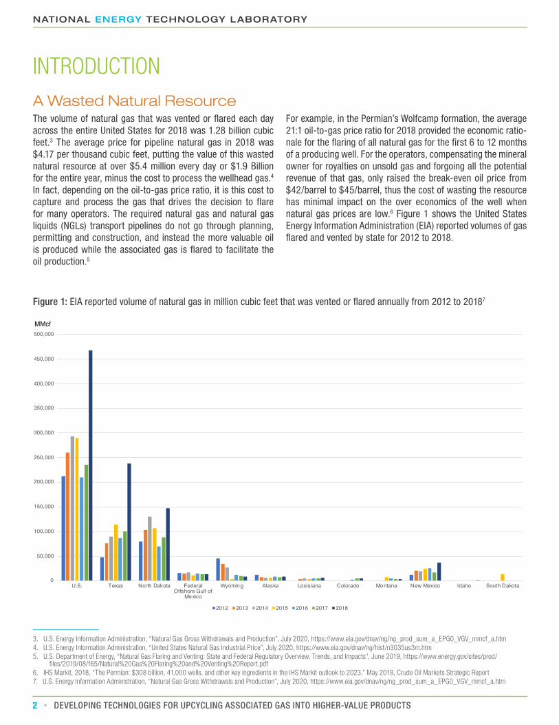
For example, in the Permian’s Wolfcamp formation, the average 21:1 oil-to-gas price ratio for 2018 provided the economic ratio-nale for the flaring of all natural gas for the first 6 to 12 months of a producing well. For the operators, compensating the mineral owner for royalties on unsold gas and forgoing all the potential revenue of that gas, only raised the break-even oil price from $42/barrel to $45/barrel, thus the cost of wasting the resource has minimal impact on the over economics of the well when natural gas prices are low.6 Figure 1 shows the United States Energy Information Administration (EIA) reported volumes of gas flared and vented by state for 2012 to 2018.
Figure 1: EIA reported volume of natural gas in million cubic feet that was vented or flared annually from 2012 to 20187
0
50,000
100,000
150,000
200,000
250,000
300,000
350,000
400,000
450,000
500,000
U.S. Texas North Dakota FederalOffshore Gulf of
Mexico
Wyoming Alaska Louisiana Colorado Montana New Mexico Idaho South Dakota
2012 2013 2014 2015 2016 2017 2018
MMcf

WWW.NETL.DOE.GOV
3DEVELOPING TECHNOLOGIES FOR UPCYCLING ASSOCIATED GAS INTO HIGHER-VALUE PRODUCTS
The Environmental Impact of Natural Gas Flaring
8. The World Bank Global Gas Flaring Reduction Partnership, “Global Gas Flaring Tracker Report”, July 2020, http://pubdocs.worldbank.org/en/503141595343850009/WB-GGFR-Re-port-July2020.pdf
9. U.S. Energy Information Administration, “Greenhouse Gas Equivalencies Calculator”, March 2020, https://www.epa.gov/energy/greenhouse-gas-equivalencies-calculator10. U.S. EPA Office of Air Quality Planning and Standards (OAQPS), “Parameters for Properly Designed and Operated Flares”, April 2012, https://www3.epa.gov/ttn/atw/flare/2012flare-
techreport.pdf11. Torres, Vincent M., et al. “Industrial Flare Performance at Low Flow Conditions. 1. Study Overview.” Industrial & Engineering Chemistry Research, vol. 51, no. 39, 2012, pp.
12559–12568., doi:10.1021/ie202674t12. Slaski, Jan J., et al. “Evaluation of Polycyclic Aromatic Hydrocarbon (PAH) Accumulation in Plants: the Potential Use of PAH Accumulation as a Marker of Exposure to Air Emissions
from Oil and Gas Flares /.” 2000, doi:10.5962/bhl.title.11565913. Ana, Gree, et al. “Polycyclic Aromatic Hydrocarbon Burden in Ambient Air in Selected Niger Delta Communities in Nigeria.” Journal of the Air & Waste Management Association,
vol. 62, no. 1, 2011, pp. 18–25., doi:10.1080/10473289.2011.628900.14. Ventura County Air Pollution Control District, “AB 2588 Combustion Emission Factors” May 2001, http://www.aqmd.gov/docs/default-source/permitting/toxics-emission-fac-
tors-from-combustion-process-.pdf?sfvrsn=015. United States Environmental Protection Agency, “Black Carbon Research”, March 2020, https://www.epa.gov/air-research/black-carbon-research16. Gray, Vincent. “Climate Change 2007: The Physical Science Basis Summary for Policymakers.” Energy & Environment, vol. 18, no. 3-4, 2007, pp. 433–440.,
doi:10.1260/09583050778107619417. Schwarz, Joshua P., et al. “Black Carbon Emissions from the Bakken Oil and Gas Development Region.” Environmental Science & Technology Letters, vol. 2, no. 10, 2015, pp.
281–285., doi:10.1021/acs.estlett.5b0022518. Fawole, Olusegun G., et al. “Gas Flaring and Resultant Air Pollution: A Review Focusing on Black Carbon.” Environmental Pollution, vol. 216, 2016, pp. 182–197., doi:10.1016/j.
envpol.2016.05.07519. Stohl, A., et al. “Black Carbon in the Arctic: the Underestimated Role of Gas Flaring and Residential Combustion Emissions.” Atmospheric Chemistry and Physics, vol. 13, no. 17,
2013, pp. 8833–8855., doi:10.5194/acp-13-8833-201320. Environmental Integrity Project, “Fact Sheet on Air Pollution from Flares”, April 2015, https://environmentalintegrity.org/news/fact-sheet-on-air-pollution-from-flares/
Besides wasting a valuable natural resource, flaring of natural gas has a negative impact on air quality and increases green-house gas emissions. The World Bank estimates that 400 million tons of carbon dioxide (including carbon dioxide (CO2) equivalent from Nitrous Oxide and Methane) is being released globally each year from natural gas flares, a value that is potentially on the rise in part due to a 23 percent increase from 2018 to 2019 in flaring in the United States.8 The CO2 released from flares in North America alone has been reported by the International En-ergy Agency to have increased from 10.6 million tons of CO2 in 2006 to 36.7 million tons of CO2 in 2018. This value represents the same amount of CO2 that would be emitted when supplying the full annual energy use of 3.8 million homes or over 7 million passenger vehicles.9 These values assume highly efficient com-bustion in the flare, and the Environmental Protection Agency (EPA) regulates flaring parameters that affect combustion to ensure proper operation, but intermittent periods of venting and incomplete combustion can result in more potent greenhouse gases being directly released to the atmosphere, such as carbon monoxide or uncombusted hydrocarbons like methane.10 In the case of incomplete combustion, some studies have shown that carbon monoxide can represent up to 80 percent of the total flare emissions.11 Chemicals that are supposed to be destroyed in the flare, including hazardous polycyclic aromatic hydrocar-bons (PAH) like naphthalene and aromatics like benzene and tol-uene, have also been measured in flare emissions with evidence of contamination detectable in the surrounding vegetation.12 Flaring of natural gas also degrades the surrounding air quality with other volatile organic compounds (VOCs) like formaldehyde and gases such as sulfur dioxide and nitrous oxides (SOx and NOx), with field sampling studies showing persistence of these chemicals almost a third of a mile downwind of the flare.13, 14
Solid particulate matter from flares has a potentially shorter im-pact on air quality due to quick deposition, but even as it settles out of the air it still impacts the environment. “Black carbon” is the term used for soot caused by burning of fossil fuels. After negatively affecting human health as air pollutant, black carbon then deposits and decreases the Earth’s ability to reflect the heat of the sun, a phenomenon particularly of concern for typ-ically light-colored artic snow and ice.15 Black carbon sources also include vehicle engines and coal-fired power plants, with the total contribution to global warming reported as second only to CO2 emissions in a 2007 report to policy makers.16 The con-tribution to black carbon pollution from natural gas flares has been reported in varying degrees of severity. A 2014 effort to measure black carbon atmospheric concentration over the Bak-ken using a research aircraft photometer concluded that four tons of black carbon was being emitted each day from flaring, but that amount was deemed insignificant since it represented less than one percent of all soot emitted in North America.17 However some simulations have shown global natural gas flares contributing to more than a 40 percent increase in the annual mean of surface black carbon in the Arctic.18, 19 While flaring is considered by the EPA as a means for destruction of harmful chemicals and a way to control pollution, the combustion of unprocessed wellhead gas is proving to be more of an environ-mental issue than originally estimated.20
NATIONAL ENERGY TECHNOLOGY LABORATORY
4 DEVELOPING TECHNOLOGIES FOR UPCYCLING ASSOCIATED GAS INTO HIGHER-VALUE PRODUCTS
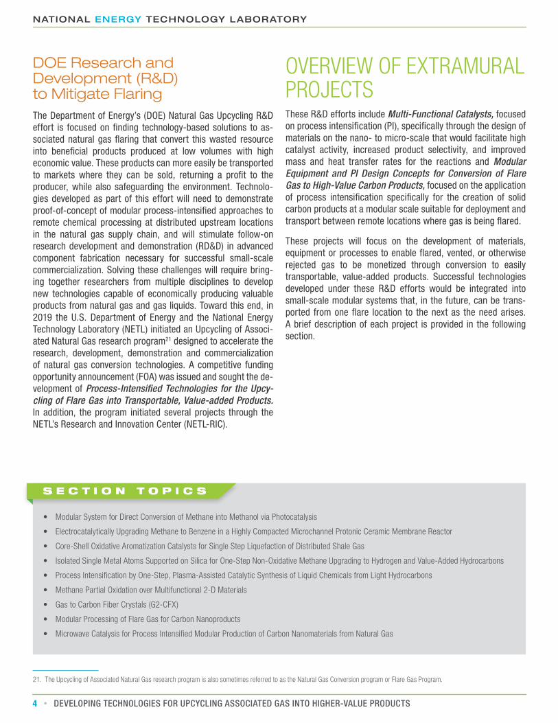
DOE Research and Development (R&D) to Mitigate FlaringThe Department of Energy’s (DOE) Natural Gas Upcycling R&D effort is focused on finding technology-based solutions to as-sociated natural gas flaring that convert this wasted resource into beneficial products produced at low volumes with high economic value. These products can more easily be transported to markets where they can be sold, returning a profit to the producer, while also safeguarding the environment. Technolo-gies developed as part of this effort will need to demonstrate proof-of-concept of modular process-intensified approaches to remote chemical processing at distributed upstream locations in the natural gas supply chain, and will stimulate follow-on research development and demonstration (RD&D) in advanced component fabrication necessary for successful small-scale commercialization. Solving these challenges will require bring-ing together researchers from multiple disciplines to develop new technologies capable of economically producing valuable products from natural gas and gas liquids. Toward this end, in 2019 the U.S. Department of Energy and the National Energy Technology Laboratory (NETL) initiated an Upcycling of Associ-ated Natural Gas research program21 designed to accelerate the research, development, demonstration and commercialization of natural gas conversion technologies. A competitive funding opportunity announcement (FOA) was issued and sought the de-velopment of Process-Intensified Technologies for the Upcy-cling of Flare Gas into Transportable, Value-added Products. In addition, the program initiated several projects through the NETL’s Research and Innovation Center (NETL-RIC).
21. The Upcycling of Associated Natural Gas research program is also sometimes referred to as the Natural Gas Conversion program or Flare Gas Program.
OVERVIEW OF EXTRAMURAL PROJECTS These R&D efforts include Multi-Functional Catalysts, focused on process intensification (PI), specifically through the design of materials on the nano- to micro-scale that would facilitate high catalyst activity, increased product selectivity, and improved mass and heat transfer rates for the reactions and Modular Equipment and PI Design Concepts for Conversion of Flare Gas to High-Value Carbon Products, focused on the application of process intensification specifically for the creation of solid carbon products at a modular scale suitable for deployment and transport between remote locations where gas is being flared.
These projects will focus on the development of materials, equipment or processes to enable flared, vented, or otherwise rejected gas to be monetized through conversion to easily transportable, value-added products. Successful technologies developed under these R&D efforts would be integrated into small-scale modular systems that, in the future, can be trans-ported from one flare location to the next as the need arises. A brief description of each project is provided in the following section.
• Modular System for Direct Conversion of Methane into Methanol via Photocatalysis
• Electrocatalytically Upgrading Methane to Benzene in a Highly Compacted Microchannel Protonic Ceramic Membrane Reactor
• Core-Shell Oxidative Aromatization Catalysts for Single Step Liquefaction of Distributed Shale Gas
• Isolated Single Metal Atoms Supported on Silica for One-Step Non-Oxidative Methane Upgrading to Hydrogen and Value-Added Hydrocarbons
• Process Intensification by One-Step, Plasma-Assisted Catalytic Synthesis of Liquid Chemicals from Light Hydrocarbons
• Methane Partial Oxidation over Multifunctional 2-D Materials
• Gas to Carbon Fiber Crystals (G2-CFX)
• Modular Processing of Flare Gas for Carbon Nanoproducts
• Microwave Catalysis for Process Intensified Modular Production of Carbon Nanomaterials from Natural Gas
S E C T I O N T O P I C S

WWW.NETL.DOE.GOV
5DEVELOPING TECHNOLOGIES FOR UPCYCLING ASSOCIATED GAS INTO HIGHER-VALUE PRODUCTS
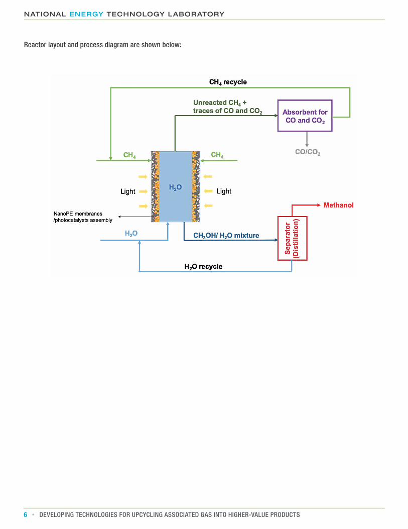
Modular System for Direct Conversion of Methane into Methanol via PhotocatalysisThis two-year project, proposed by Stanford University, will develop a process for photocatalytic activation of methane at a gas-water interface such that methanol can be formed at ambient temperature. The modular reactor will be developed to use pressurized gas through a photocatalytic membrane wall supported on nano-porous polyethylene. Under standard ultra-violet light, hydroxyl radicals will be generated that then create
subsequent methyl radicals that can be synthesized to methanol by a co-catalyst also in the reactor wall. The methanol then dissolves into the liquid phase portion of the reactor to avoid over-oxidation. This project’s task list includes optimization of the bi-functional catalyst to achieve high selectivity and meth-ane conversion efficiency at ambient temperatures.
Key advantages of the proposed method include:• Methane to methanol conversion demonstrated with 90 percent
methanol selectivity, 5 times higher than other state-of-art liquid phase reactions
• Overcomes reaction kinetics limitations and water extraction requirements of gas-phase reactors that employ stepwise oxidation of methane to prevent over-oxidation
• Liquid-phase solvation helps stabilize products and critical intermediate compounds
• Use of photon energy allows for low-temperature reaction
NATIONAL ENERGY TECHNOLOGY LABORATORY
6 DEVELOPING TECHNOLOGIES FOR UPCYCLING ASSOCIATED GAS INTO HIGHER-VALUE PRODUCTS
Reactor layout and process diagram are shown below:
WWW.NETL.DOE.GOV
7DEVELOPING TECHNOLOGIES FOR UPCYCLING ASSOCIATED GAS INTO HIGHER-VALUE PRODUCTS
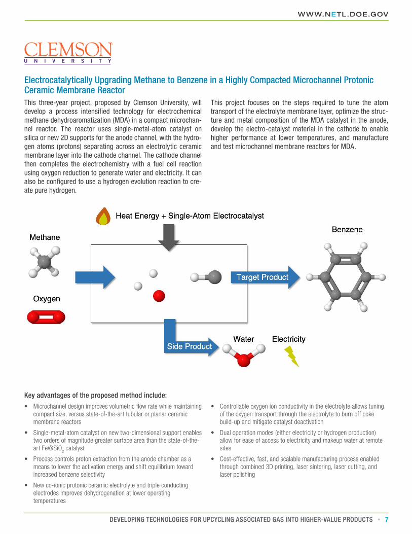
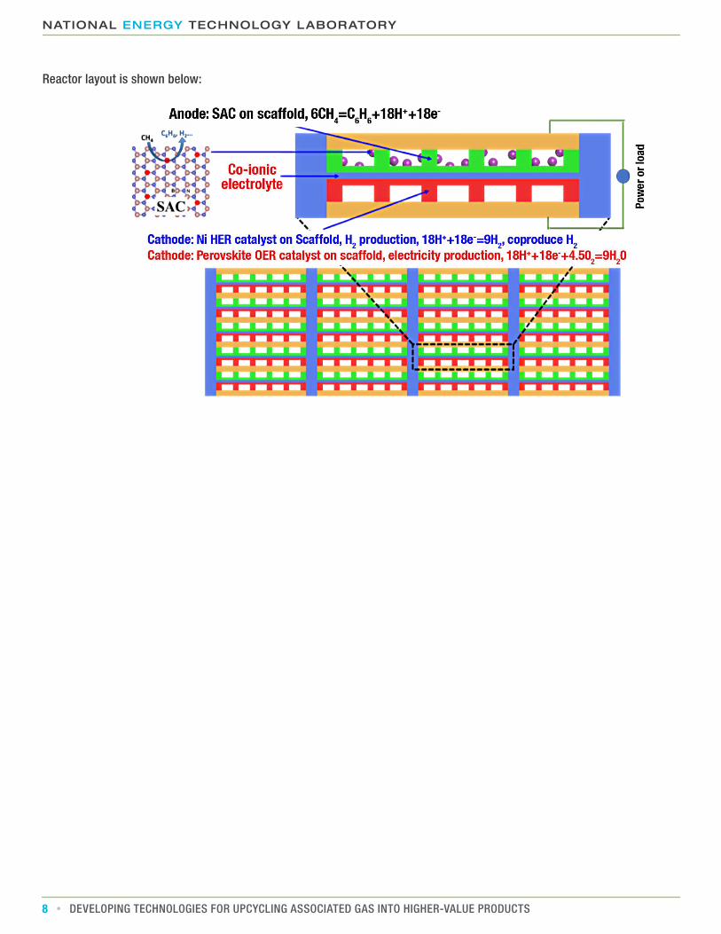
Electrocatalytically Upgrading Methane to Benzene in a Highly Compacted Microchannel Protonic Ceramic Membrane ReactorThis three-year project, proposed by Clemson University, will develop a process intensified technology for electrochemical methane dehydroaromatization (MDA) in a compact microchan-nel reactor. The reactor uses single-metal-atom catalyst on silica or new 2D supports for the anode channel, with the hydro-gen atoms (protons) separating across an electrolytic ceramic membrane layer into the cathode channel. The cathode channel then completes the electrochemistry with a fuel cell reaction using oxygen reduction to generate water and electricity. It can also be configured to use a hydrogen evolution reaction to cre-ate pure hydrogen.
This project focuses on the steps required to tune the atom transport of the electrolyte membrane layer, optimize the struc-ture and metal composition of the MDA catalyst in the anode, develop the electro-catalyst material in the cathode to enable higher performance at lower temperatures, and manufacture and test microchannel membrane reactors for MDA.
Key advantages of the proposed method include:• Microchannel design improves volumetric flow rate while maintaining
compact size, versus state-of-the-art tubular or planar ceramic membrane reactors
• Single-metal-atom catalyst on new two-dimensional support enables two orders of magnitude greater surface area than the state-of-the-art Fe@SiO
2 catalyst
• Process controls proton extraction from the anode chamber as a means to lower the activation energy and shift equilibrium toward increased benzene selectivity
• New co-ionic protonic ceramic electrolyte and triple conducting electrodes improves dehydrogenation at lower operating temperatures
• Controllable oxygen ion conductivity in the electrolyte allows tuning of the oxygen transport through the electrolyte to burn off coke build-up and mitigate catalyst deactivation
• Dual operation modes (either electricity or hydrogen production) allow for ease of access to electricity and makeup water at remote sites
• Cost-effective, fast, and scalable manufacturing process enabled through combined 3D printing, laser sintering, laser cutting, and laser polishing
NATIONAL ENERGY TECHNOLOGY LABORATORY
8 DEVELOPING TECHNOLOGIES FOR UPCYCLING ASSOCIATED GAS INTO HIGHER-VALUE PRODUCTS
Reactor layout is shown below:

WWW.NETL.DOE.GOV
9DEVELOPING TECHNOLOGIES FOR UPCYCLING ASSOCIATED GAS INTO HIGHER-VALUE PRODUCTS
Core-Shell Oxidative Aromatization Catalysts for Single Step Liquefaction of Distributed Shale GasThis three-year project, proposed by NC State University, will design and demonstrate a multifunctional catalyst for con-version of methane, ethane, and propane to liquid aromatics through dehydroaromatization coupled with selective hydrogen combustion. This catalyst uses a zeolite-based outer shell for dehydroaromatization that is grafted onto a cubic-structured oxide core (perovskite-structured) that uses oxidative reduction on the removed hydrogen to form water.
Tasks for the project will evaluate the ratio and compositions of the core and shell materials as well as tunable and scalable synthesis procedures. The project will employ the developed catalyst to build a modular fixed bed autothermal reactor that incorporates catalyst regeneration and recycling of unconverted light hydrocarbons.
Key advantages of the proposed method include:• Core-shell arrangement provides a unique tunable catalyst structure
for enhanced coke-resistance and higher product selectivity/yield versus current state-of-the-art
• Hydrogen combustion enables autothermal reaction and removes any external utility requirements, such as the requirement of a power source and units for hydrogen removal
• Perovskite-structured core increases benzene and toluene yields
• Fixed bed reactor design avoids membrane stability issues seen with membrane-based hydrogen removal methods
• Permeation of water by-product from catalyst core through zeolite shell reduces carbon build-up
• Acceptance of mixtures of higher hydrocarbons allows for eventual application at natural gas production sites

NATIONAL ENERGY TECHNOLOGY LABORATORY
10 DEVELOPING TECHNOLOGIES FOR UPCYCLING ASSOCIATED GAS INTO HIGHER-VALUE PRODUCTS
Reactor layout and process diagram are shown below:
Parallel Packed beds
Pallet sized OAS reactor module (insulation not shown)
Valve Manifolds
Power Gen.
Sep.
Integrated Heat Exchange
Simple Air Compressor
Gas engine
Proposed Catalyst Structure is shown below:

WWW.NETL.DOE.GOV
11DEVELOPING TECHNOLOGIES FOR UPCYCLING ASSOCIATED GAS INTO HIGHER-VALUE PRODUCTS
Isolated Single Metal Atoms Supported on Silica for One-Step Non-Oxidative Methane Upgrading to Hydrogen and Value-Added HydrocarbonsThis three-year project, proposed by the University of Maryland, will enable efficient, non-oxidative coupling of methane, ethane and propane via development of an inexpensive and resilient catalyst that uses isolated single metal atoms supported on sil-ica. This project targets higher reaction temperatures to better promote homogeneous gas-phase reactions, while hypothesiz-ing that the pooling of hydrocarbons on the heterogeneous solid
catalyst near the active site will serve as a mechanism to limit coke formation. Project tasks include the prototyping of a low-cost reactor that operates in an autothermal manner by com-busting coke and builds the silica-supported catalyst directly into the reactor wall. Optimization efforts will focus on the novel catalytic-wall reactor concept and operating conditions and will evaluate different metal atoms as the active site in the catalyst.
Key advantages of the proposed method include:• Low-cost reactor design via autothermal operation under moderate
to low pressures with fewer steps
• Low-cost catalyst operates at higher temperatures (950-1090°C) and increases homogeneous gas-phase reactions while decreasing catalyst deactivation versus state-of-the art zeolite catalysts
• Isolation of metal atoms generates a hydrocarbon pool that reduces coke formation versus other catalysts that use metal atom ensembles
• Low-surface-area catalyst development strategy with high-temperature operation enables purposefully controlled coupling of surface and gas reactions that can create higher product yields

NATIONAL ENERGY TECHNOLOGY LABORATORY
12 DEVELOPING TECHNOLOGIES FOR UPCYCLING ASSOCIATED GAS INTO HIGHER-VALUE PRODUCTS
Reactor layout and process diagram are shown below:
CH4 recycleNatural Gas
CO2/Air
CO2 + Air
Air
CH4 purge
Aromatics
authothermal reactor
Air stream Product stream
Heat �owCH4 recycleFuel stream
CH4
H2
CH4/C2
CH4/C2
C2
CH4
mixercompressorheat exchanger
coolerseperator
Q
QCH4
C2+
+Coke
+ O
2 C
O 2
Coke
+ O
2 C
O 2
Coke
Proposed Catalyst Synthesis and Structure is shown below:
WWW.NETL.DOE.GOV
13DEVELOPING TECHNOLOGIES FOR UPCYCLING ASSOCIATED GAS INTO HIGHER-VALUE PRODUCTS
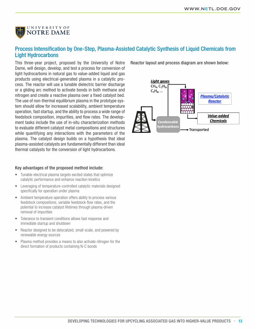
Process Intensification by One-Step, Plasma-Assisted Catalytic Synthesis of Liquid Chemicals from Light HydrocarbonsThis three-year project, proposed by the University of Notre Dame, will design, develop, and test a process for conversion of light hydrocarbons in natural gas to value-added liquid and gas products using electrical-generated plasma in a catalytic pro-cess. The reactor will use a tunable dielectric barrier discharge or a gliding arc method to activate bonds in both methane and nitrogen and create a reactive plasma over a fixed catalyst bed. The use of non-thermal equilibrium plasma in the prototype sys-tem should allow for increased scalability, ambient temperature operation, fast startup, and the ability to process a wide range of feedstock composition, impurities, and flow rates. The develop-ment tasks include the use of in-situ characterization methods to evaluate different catalyst metal compositions and structures while quantifying any interactions with the parameters of the plasma. The catalyst design builds on a hypothesis that ideal plasma-assisted catalysts are fundamentally different than ideal thermal catalysts for the conversion of light hydrocarbons.
Key advantages of the proposed method include:• Tunable electrical plasma targets excited states that optimize
catalytic performance and enhance reaction kinetics
• Leveraging of temperature-controlled catalytic materials designed specifically for operation under plasma
• Ambient temperature operation offers ability to process various feedstock compositions, variable feedstock flow rates, and the potential to increase catalyst lifetimes through plasma-driven removal of impurities
• Tolerance to transient conditions allows fast response and immediate startup and shutdown
• Reactor designed to be delocalized, small-scale, and powered by renewable energy sources
• Plasma method provides a means to also activate nitrogen for the direct formation of products containing N-C bonds
Reactor layout and process diagram are shown below:

NATIONAL ENERGY TECHNOLOGY LABORATORY
14 DEVELOPING TECHNOLOGIES FOR UPCYCLING ASSOCIATED GAS INTO HIGHER-VALUE PRODUCTS
Methane Partial Oxidation over Multifunctional 2-D MaterialsThis three-year project, proposed by the University of South Carolina, plans to create a scalable process for partial oxida-tion of methane to methanol using a set of multifunctional, graphene-doped materials as selective catalysts. The catalyst design is based on the concept that a metal site responsible for C-H activation can be embedded in a material that can activate molecular oxygen. To break the scaling relations of the C-H ac-tivation in methane and methanol, and to prevent over-oxidation of the reaction product, it requires strong interactions between the methyl group and the metal site as well as a physical driving force that distinguishes the transition state for the C-H bond
activation in methane and methanol. Since the carbon atom in methane is slightly negative while it is slightly positive in meth-anol, a partial positive charge invoked in the active metal site will leverage this difference in charge on the carbon atom as the driving force for high selectivity. The catalyst development tasks will utilize computational modeling, including microkinetic and full reactor simulations, in order to find the optimal system that can achieve high single-pass yields. Computation models will be validated by lab experimentation and the results will be integrated back into the simulation to improve predictability, driving further iterations of the catalyst.
Key advantages of the proposed method include:• Heterogeneous, catalytic vapor phase process utilizes molecular
oxygen for the direct oxidation of methane to methanol, and avoids catalyst stability and product separation issues associated with homogeneous and/or liquid-phase processes
• Low-temperature process permits small scale applications in remote locations close to shale oil and natural gas sites
• Improved methanol selectivity with predicted reaction rates that are four orders of magnitude larger than those measured with existing copper-based zeolite catalysts promise high single-pass yields
• Process intensification based on precise control of active sites in heterogeneous catalysts
• State-of-the-art computational tools are integrated with modern experimental methods at both the atomistic and reactor scale

WWW.NETL.DOE.GOV
15DEVELOPING TECHNOLOGIES FOR UPCYCLING ASSOCIATED GAS INTO HIGHER-VALUE PRODUCTS
Process diagram is shown below:
Proposed Catalyst Structure is shown below:
CO2
Partial neg. charge
Partial pos. charge
O2
CH4

NATIONAL ENERGY TECHNOLOGY LABORATORY
16 DEVELOPING TECHNOLOGIES FOR UPCYCLING ASSOCIATED GAS INTO HIGHER-VALUE PRODUCTS
Gas to Carbon Fiber Crystals (G2-CFX)In this three-year project, PARC plans to develop a process for producing high-performance carbon fibers, where the carbon feedstock is sourced from the pyrolysis of wellhead natural gas. The proposed wellhead gas-to-carbon fiber scheme consists of two distinct technologies, methane pyrolysis and carbon fiber production. A modular, aerosol-catalyst-assisted methane pyrolysis unit converts wellhead natural gas into hydrogen gas and carbon powder, where the carbon is then transported to a facility that converts it to carbon fiber. Due to the high value of the final carbon fiber product, the proposed process can potentially be an economical alternative to natural gas flaring. The use of low-cost carbon feed—in contrast to the expensive polyacrylonitrile precursor used in state-of-the-art carbon fiber production—can potentially lower the carbon fiber cost by
one-third and enable penetration into the automobile market by achieving cost-parity with steel for autobody parts. The core technology for the aerosol-catalyst-assisted methane pyrolysis process is concurrently being evaluated and developed, under an ARPA-E-funded project, for large-scale hydrogen production. To enable this technology, the methane pyrolysis technology will be evaluated, optimized and engineered for carbon production and for operation at oil and natural gas well sites. By the end of this project, PARC aims to demonstrate a bench-scale prototype that produces a single carbon-fiber tow comprising of 1,000 fibers, where the carbon feed represents that derived from wellhead natural gas pyrolysis. A complete wellhead gas-to-carbon fiber scheme will be conceptually designed at the pilot plant scale to address 50,000 cubic feet of natural gas per day.
Key advantages of the proposed method include:• Enables high methane conversion (greater than 90 percent) due to
the use of a high-surface-area, aerosolized metal droplets as the catalyst for the methane pyrolysis reaction
• Ease of removing common flare gas contaminants in the methane pyrolysis step due to favorable reaction with the catalyst used
• Novel method produces carbon fibers using low-cost carbon powders, enabling lower production costs
• Economic viability at a natural gas capacity of 50,000 cubic feet per day using a modular and process-intensified process

WWW.NETL.DOE.GOV
17DEVELOPING TECHNOLOGIES FOR UPCYCLING ASSOCIATED GAS INTO HIGHER-VALUE PRODUCTS
Process diagram is shown below:
NATIONAL ENERGY TECHNOLOGY LABORATORY
18 DEVELOPING TECHNOLOGIES FOR UPCYCLING ASSOCIATED GAS INTO HIGHER-VALUE PRODUCTS
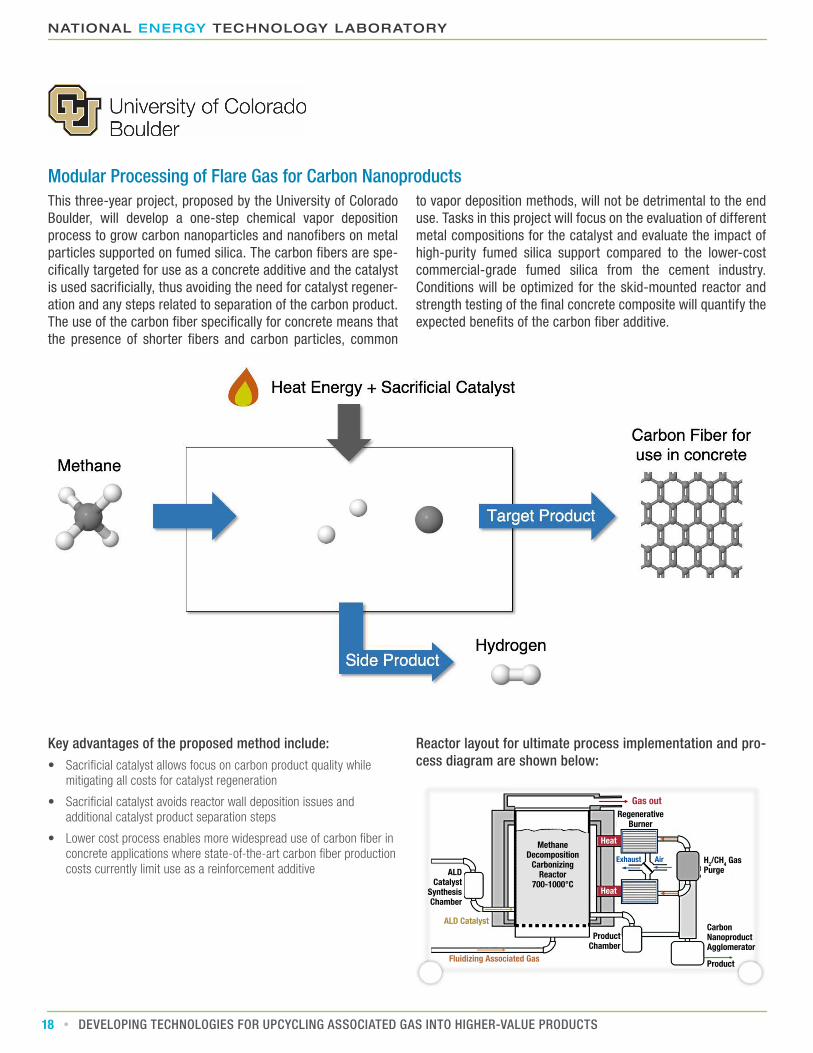
Modular Processing of Flare Gas for Carbon NanoproductsThis three-year project, proposed by the University of Colorado Boulder, will develop a one-step chemical vapor deposition process to grow carbon nanoparticles and nanofibers on metal particles supported on fumed silica. The carbon fibers are spe-cifically targeted for use as a concrete additive and the catalyst is used sacrificially, thus avoiding the need for catalyst regener-ation and any steps related to separation of the carbon product. The use of the carbon fiber specifically for concrete means that the presence of shorter fibers and carbon particles, common
to vapor deposition methods, will not be detrimental to the end use. Tasks in this project will focus on the evaluation of different metal compositions for the catalyst and evaluate the impact of high-purity fumed silica support compared to the lower-cost commercial-grade fumed silica from the cement industry. Conditions will be optimized for the skid-mounted reactor and strength testing of the final concrete composite will quantify the expected benefits of the carbon fiber additive.
Key advantages of the proposed method include:• Sacrificial catalyst allows focus on carbon product quality while
mitigating all costs for catalyst regeneration
• Sacrificial catalyst avoids reactor wall deposition issues and additional catalyst product separation steps
• Lower cost process enables more widespread use of carbon fiber in concrete applications where state-of-the-art carbon fiber production costs currently limit use as a reinforcement additive
Reactor layout for ultimate process implementation and pro-cess diagram are shown below:
Regenerative Burner
ALD Catalyst
Synthesis Chamber
Product Chamber
Carbon Nanoproduct Agglomerator
H2/CH4 Gas Purge
Product
ALD Catalyst
Fluidizing Associated Gas
Gas out
Exhaust Air
Heat
Heat
Methane Decomposition
Carbonizing Reactor
700-1000°C

WWW.NETL.DOE.GOV
19DEVELOPING TECHNOLOGIES FOR UPCYCLING ASSOCIATED GAS INTO HIGHER-VALUE PRODUCTS
Microwave Catalysis for Process Intensified Modular Production of Carbon Nanomaterials from Natural GasThis three-year project, proposed by West Virginia University, plans to develop a new, low-cost modular process that directly converts flare gas to carbon nanomaterials and hydrogen using a single step, microwave-enhanced, multifunctional catalytic system. This method produces high quality carbon nanotubes and carbon fibers and uses a solvent-based process to regener-ate the catalyst and separate it from the carbon product. Project efforts will focus on the development of the electromagnetic sensitive catalysts, such as aerogel-based catalyst, in areas specific to the use of microwave energy, including tuning di-electric properties that improve microwave adsorption and the
use of metallic dopants to adjust magnetic coupling. The project will also evaluate the impact of the microwave field, including kinetic modeling, fixed versus variable frequency microwaves, and tuning to intermediate species in order to decrease energy lost to the surroundings. Prototype reactors of two different siz-es will be constructed and the impacts of process parameters like microwave frequency, input power, and temperature on the formation rate and properties of carbon nanomaterials will be investigated. The impacts of various hydrocarbon compositions in the feedstock gas will also be evaluated.
Key advantages of the proposed method include:• Improved energy efficiency, simplified catalyst regeneration, and
high-quality product that is easily separated from the process stream
• Microwave process enables selective bond activation and produces crystalline carbon, unlike the state-of-the-art thermal decomposition and non-catalytic plasma decomposition methods
• Aerogel catalyst is designed to be electromagnetically sensitive and stable under microwave plasma to achieve high conversion and selectivity, while avoiding issues associated with thermal methods like overheating of metal sites and metal sintering
• Patent pending fluidized bed microwave plasma reaction process capable of sustaining direct contact between microwave plasma and the catalyst particles without requiring dielectric separation or dilution of the feedstock that is typically needed by microwave-based systems to prevent arc-discharging
• Solution-based product separation enables reuse of the dissolved metal catalyst and avoids the large energy consumption of other separation methods requiring high temperatures or high electrical power inputs

NATIONAL ENERGY TECHNOLOGY LABORATORY
20 DEVELOPING TECHNOLOGIES FOR UPCYCLING ASSOCIATED GAS INTO HIGHER-VALUE PRODUCTS
Process diagram is shown below:
Proposed Catalyst Synthesis and Structure is shown below:
Oil bath
Oil bath
80°C,1 h
80°C,1 h
Wet gel
Wet gel
Ni/Al2O3 Aerogel
Co/Al2O3 Aerogel
Ni/Al2O3 Aerogel Catalyst
Co/Al2O3 Aerogel Catalyst
Ni/Al2O3 Aerogel Catalyst
Co/Al2O3 Aerogel Catalyst
1) Annealing
1) Annealing
Produced
COx-Free Hydrogen
Non COx-Free Hydrogen
Base growth CNTs
Tip Growth and Base growth CNTs
COx-Free Hydrogen
Non COx-Free Hydrogen
Base growth CNTs
Tip Growth and Base growth CNTs
Produced
2) 10% H2/N2 Reduction
2) 10% H2/N2 Reduction
3) 30% CH4/N2 Reaction
3) 30% CH4/N2 Reaction
Drying
Drying
WWW.NETL.DOE.GOV
21DEVELOPING TECHNOLOGIES FOR UPCYCLING ASSOCIATED GAS INTO HIGHER-VALUE PRODUCTS
OVERVIEW OF NETL FIELD WORK PROPOSAL (FWP) PROJECTS A field work proposal (FWP) titled Upcycling of Associated Natural Gas Field Work Proposal was issued by NETL in 2020 on topics that related closely to DE-FOA-0002006 AOI 2. The objective of this FWP was to deliver field validated, technical solutions to reduce well pad flare-related emissions while mon-etizing the captured natural gas. The effort focused on a variety of wellhead deployable technical solutions to convert natural gas to high-value commodities easily absorbed into the market-place via novel thermo-catalytic, microwave (MW)-assisted, or electrochemical processes.
In total, four projects were selected from the FWP. A short de-scription of each project is provided on the following pages.
• Electrochemical Upgrading of Flare Gas
• Production of Hydrogen and Carbon from Catalytic Flare Gas Pyrolysis
• Commercialization Study of NETL Technology for Flare Gas to Olefins and Liquids
• Microwave Enhanced Flare Gas Conversion to Value-Added Chemicals
S E C T I O N T O P I C S

NATIONAL ENERGY TECHNOLOGY LABORATORY
22 DEVELOPING TECHNOLOGIES FOR UPCYCLING ASSOCIATED GAS INTO HIGHER-VALUE PRODUCTS
Electrochemical Upgrading of Flare GasThis four- to five-year project proposes to develop electrochemi-cal technologies to convert flare gas into high-demand industrial olefins like ethylene. This project plans to enhance production rates and improve production selectively compared to traditional oxidative coupling and dehydrogenation though optimization of perovskite-structured catalysts on the anode. Oxygen from air is reduced at the cathode to produce oxygen ions (O2-) and H2O. Captured CO2 can also be used to produce O2- and CO. The resulting O2- ions are transported through the electrolyte layer and react with natural gas components at the anode catalyst to
produce higher-value hydrocarbons. The produce selectivity and overall reactions rates can be controlled by applying electro-chemical potentials between the anode and cathode catalysts. to improve product selectivity and overall reaction rates. The composition of the anode catalyst and solid oxide electrolyte can also be tuned to target dehydrogenation of ethane into ethylene. The targeted electrochemical process will be prototyped in a small-scale modular reactor to demonstrate selective conver-sion of various compositions of methane, ethane and propane found in natural gas.
Key advantages of the proposed method include:• Small footprint modular reactor design with enhanced production
rates for improved product selectivity compared to state-of-the-art oxidative coupling and dehydrogenation
• Tuned perovskite composition and electrochemical potentials will increase product selectivity and reduce catalyst deactivation
• Catalyst and electrolyte formulation can be adjusted to target methane or ethane feedstock
• Oxygen (from air) or captured CO2 can be used as an oxygen ion source
• Leverages existing solid-oxide fuel cell designs that have been industrially demonstrated for distributed electricity production from natural gas
Electrolyzer schematic is shown below:
WWW.NETL.DOE.GOV
23DEVELOPING TECHNOLOGIES FOR UPCYCLING ASSOCIATED GAS INTO HIGHER-VALUE PRODUCTS
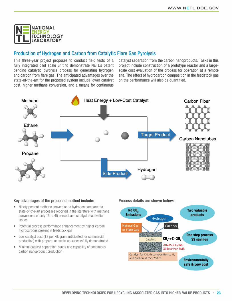
Production of Hydrogen and Carbon from Catalytic Flare Gas PyrolysisThis three-year project proposes to conduct field tests of a fully integrated pilot scale unit to demonstrate NETL’s patent pending catalytic pyrolysis process for generating hydrogen and carbon from flare gas. The anticipated advantages over the state-of-the-art for the proposed system include lower catalyst cost, higher methane conversion, and a means for continuous
catalyst separation from the carbon nanoproducts. Tasks in this project include construction of a prototype reactor and a large-scale cost evaluation of the process for operation at a remote site. The effect of hydrocarbon composition in the feedstock gas on the performance will also be quantified.
Key advantages of the proposed method include:• Ninety percent methane conversion to hydrogen compared to
state-of-the-art processes reported in the literature with methane conversions of only 16 to 45 percent and catalyst deactivation issues
• Potential process performance enhancement by higher carbon hydrocarbons present in feedstock gas
• Low catalyst cost ($3 per kilogram anticipated for commercial production) with preparation scale-up successfully demonstrated
• Minimal catalyst separation issues and capability of continuous carbon nanoproduct production
Process details are shown below:
Environmentally safe & Low cost
One step process $$ savings
Two valuable products
No CO2 Emissions
CH4->C+2H2

NATIONAL ENERGY TECHNOLOGY LABORATORY
24 DEVELOPING TECHNOLOGIES FOR UPCYCLING ASSOCIATED GAS INTO HIGHER-VALUE PRODUCTS
Commercialization Study of NETL Technology for Flare Gas to Olefins and LiquidsThis two-year project proposes to evaluate the commercial potential of a catalyst technology developed by NETL for con-version of flare gas to olefins. The process has potential to be an inexpensive solution that uses iron oxide nanoparticles that are supported on carbon nanosheets fabricated from the car-bonization of potassium citrate. This produces a carbon support structure activated by well-dispersed potassium (K-promoter). The project will initially focus on process modeling that, if suc-
cessful, will be followed by scaled-up catalyst production and pilot scale testing with industrial partners that are licensing the technology from NETL. This project aims to make the catalyst technology available for purchase with a fully developed com-mercialization plan including patent protection, catalyst supply agreements, and the partner’s identification as “first users” of the technology.
Key advantages of the proposed method include:• Inexpensive carbon support activated by a K-promoter in a manner
unachievable with current state-of-the-art methods
• Fe-based nanocatalysts that show increased carbon monoxide conversion (>70 percent), C2-C4 olefin selectivity of 40 percent and a high olefin/paraffin ratio of 3.5
• Demonstrated reactor stability over 500 hours of testing using simulated syngas outperforms other systems based on literature reports
• Developed catalyst allows flexible application for other reactions such as CO2 hydrogenation to olefins
Catalyst Structure is shown below:

WWW.NETL.DOE.GOV
25DEVELOPING TECHNOLOGIES FOR UPCYCLING ASSOCIATED GAS INTO HIGHER-VALUE PRODUCTS
Microwave Enhanced Flare Gas Conversion to Value-Added ChemicalsThis five-year project proposes to develop and demonstrate a modular, process intensified microwave-based catalytic reactor system for the non-oxidative conversion of natural gas into C2+ olefins. The project tasks initially focus on gaining a parametric understanding of the factors that affect the conversion, includ-ing an understanding of the reaction kinetics and mechanism, as well as the influence of fixed versus variable microwave
frequencies. Catalyst development will include optimizing the electromagnetic properties and quantifying the impact of mate-rial and particle structure through experimentation and compu-tational modeling. The end goal will be the fabrication of a fully operational reactor that efficiently realizes the selective heating advantages of microwave hydrocarbon conversion by showing a 20 percent improvement in efficiency.
Key advantages of the proposed method include:• Microwave-based approach allows for selective-heating process intensification and scalable reactor design
• Higher yields at lower bulk temperatures reduce carbon formation
• Reaction intensification possible with microwave effects improves product distribution
Proposed Catalyst Synthesis and Testing is shown below:
Catalyst Synthesis
Catalyst Activity Testing
Modeling
Characterization
NETL MW ReactorReactor Tube
Electric Heaters
IR Pyrometer
Magnetron
MW
4% Mo0
1
2
3
4
5
6
7
6% Mo 3% Zn
no-MW
Benz
ene
yiel
d (%
)

NATIONAL ENERGY TECHNOLOGY LABORATORY
26 DEVELOPING TECHNOLOGIES FOR UPCYCLING ASSOCIATED GAS INTO HIGHER-VALUE PRODUCTS
NEXT STEPSWith the above projects, DOE and NETL have undertaken foun-dational research on natural gas conversion. The long-term ob-jective of this R&D effort is to advance alternatives to minimize flaring and venting during the production of oil and other normal, planned oil and natural gas system operations, through the up-cycling of natural gas into value-added, transportable products. Meeting this objective will require scientific and engineering breakthroughs in four key areas:
1. Materials Development – new catalysts and materials for gas separation, nano and microscale process intensification
2. Equipment Development – modular reactor design, macroscale process intensification
3. Process Development – balance of plant integration
4. Advanced Manufacturing – cost effective application of the first three development areas
In FY20, DOE awarded the first round of R&D funding through an extramural FOA and intramural NETL FWP. Over the next three years these projects will develop and validate their technologies. The projects under AOI 2A are at the early stages of development and are focused on proof-of-concept of new and novel catalysts and gas separation materials. Most of the selected FWP projects are also at this early stage. Successful projects from AOI 2A and the FWP will be ready for the next step in the R&D cycle, which is equipment development.
AOI 2B projects are further along and are focused on bench-scale development and testing of integrated reaction/product separation equipment. It is envisioned that successful technol-ogies developed in this R&D effort will be ready for integration into a small-scale modular prototype, which in the future can be transported from one flare site to the next.
Upon field testing under real-world conditions, successful tech-nologies will still require balance of plant integration. Supporting equipment for flare gas purification, and supporting heat, elec-tric power, cooling, etc., will need to be designed, tested and in-tegrated into a complete modular and mobile system, ready for commercial demonstration. In addition, the flare gas upcycling equipment will require advanced manufacturing techniques, such as additive manufacturing, to achieve economically viable deployment. DOE anticipates some of these efforts could begin before equipment-scale R&D is completed.
Moving forward, a follow-on R&D effort is anticipated to man-ufacture and demonstrate successful technologies from AOI 2B at field sites using actual associated natural gas and real-world conditions and to advance catalyst/separation materials to the equipment and process concepts R&D phase. In addition, the FOA AOI 2A and FWP projects selected in the first round of fund-ing only consider a small subset of value-added chemicals, such as benzene/toluene/xylene and methanol. Preliminary assess-ments conducted by Pacific Northwest National Laboratory and NETL indicate a wider range of potentially attractive products. A second round of funding will allow the nascent R&D program to examine a wider range of potential value-added products and applications, as well as gas conversion technologies not covered in the initial FOA.

2018 Bakken Flaring Report Results
* The data found in this Appendix are pulled from public sources and are not intended to be authoritative or complete.
WWW.NETL.DOE.GOV
27DEVELOPING TECHNOLOGIES FOR UPCYCLING ASSOCIATED GAS INTO HIGHER-VALUE PRODUCTS
APPENDIX:* Associated Gas Flaring Factsheet: 2018 BAKKEN
Reporting Agency
Total Annual Flared Volume (MMCF)
Total Annual CO2 Emissions (MM tonne)
Estimated Number of Flared Wells
Estimated Number of Operators
NDIC 63,329 5.23 11,982 NA
• Total Annual CO2 Emissions were calculated assuming complete combustion of flared gas volumes at STP conditions (0°C/1 atm) using the average gas composition shown below
Average Natural Gas Composition by Mol %
Play/Basin C1 C2 C3 C4 H2S CO2 N2 He OtherBAKKEN 52.7% 24.6% 12.9% 1.3% 3.8% 2.8% 0.0% 0.4% 1.6%
• Data for the average gas composition of a flare was acquired from an Eagle Ford Shale Oil Report and is calculated from an unknown number of samples
Average Flaring Volume Per Flare (MCFD)
2018 Yearly
27.4
1st Half 2nd Half
25.6 29.2
Q1 Q2 Q3 Q4
23.9 27.3 27.9 30.5
January February March April May June July August September October November December
24.5 24.9 22.4 26.8 29.8 25.2 26.3 27.3 30.1 31.4 30.7 29.3
• Flaring values are reported on a monthly basis per well and include operational flaring days
• Values were totaled and then averaged per month, per quarter, bi-annually, and yearly
• Data was acquired from the North Dakota Industrial Commission and then characterized for flaring volume calculations
• Daily flaring volumes were calculated using provided reporting information and then averaged based on a chronological period
Flare Size (MCFD)
Flare Units
Total Volume (MCFD)
<=100 3,781 99,761100-200 753 109,036200-300 442 109,508300-400 280 96,755400-500 206 92,716500-600 149 81,686600-700 140 91,261700-800 98 73,091800-900 83 70,739
900-1,000 58 54,669
• Monthly reports include flared volume in MCF (1000 ft³), operational days, location, and producing field information for each individual flare
• Daily flaring volumes were calculated by dividing the reported monthly flared volume in MCF by the number of operational days to estimate MCFD
• Flare Units represent the number of flaring reports, by flare, in the year 2018 that fell into the respective bin value
• The Total Volume represents the total volume of flared gas for all units within each size category
TOTAL
UNITS

• Monthly reports include flared volume in MCF (1000 ft³), operational days, location, and producing field information for each individual flare
• Daily flaring volumes were calculated by dividing the reported monthly flared volume in MCF by the number of days in the respective month to estimate MCFD
• Flare Units represent the number of flaring reports, by lease, in the year 2018 that fell into the respective bin value
• The Total Volume represents the total volume of flared gas for all units within each size category
TOTAL
UNITS
2018 Permian Flaring Report Results
NATIONAL ENERGY TECHNOLOGY LABORATORY
28 DEVELOPING TECHNOLOGIES FOR UPCYCLING ASSOCIATED GAS INTO HIGHER-VALUE PRODUCTS
Associated Gas Flaring Factsheet: 2018 PERMIAN
Reporting Agency
Total Annual Flared Volume (MMCF)
Total Annual CO2 Emissions (MM tonne)
Estimated Number of Leases that Flared
Estimated Number of Operators
TXRRC 88,953 5.67 8,154 225
• Total Annual CO2 Emissions were calculated assuming complete combustion of flared gas volumes at STP conditions (0°C/1 atm) using the average gas composition shown below
Average Natural Gas Composition by Mol %
Play/Basin C1 C2 C3 C4 H2S CO2 N2 He OtherPERMIAN 69.3% 11.0% 4.7% 2.0% 0.4% 1.1% 10.1% 0.1% 0.1%
• Data for the average gas composition of a flare was acquired from a multitude of sources
• A total of 19 sample points were used to determine the compositional values
• Production from the Permian can come from up to 13 different stacked reservoirs
Average Flaring Volume Per Flare (MCFD)
2018 Yearly
57.4
1st Half 2nd Half
50.1 64.7
Q1 Q2 Q3 Q4
45.1 55.0 52.0 77.3
January February March April May June July August September October November December
49.5 41.2 44.7 57.7 52.6 54.8 52.5 47.3 56.1 72.9 70.5 88.5
• Flaring values are reported on a monthly basis per lease and do not detail the total flare operational days
• Values were totaled and then averaged per month, per quarter, bi-annually, and yearly
• Data was acquired from the Texas Railroad Commission and then characterized for flaring volume calculations
• Daily flaring volumes were calculated using provided reporting information and then averaged based on a chronological period.
Flare Size (MCFD)
Flare Units
Total Volume (MCFD)
<=100 44,252 601,057100-200 2,401 339,660200-300 1,105 269,029300-400 596 205,937400-500 366 163,629500-600 240 131,329600-700 203 131,534700-800 146 108,801800-900 99 84,003
900-1,000 73 68,990
Flare Size (MCFD)
Flare Units
Total Volume (MCFD)
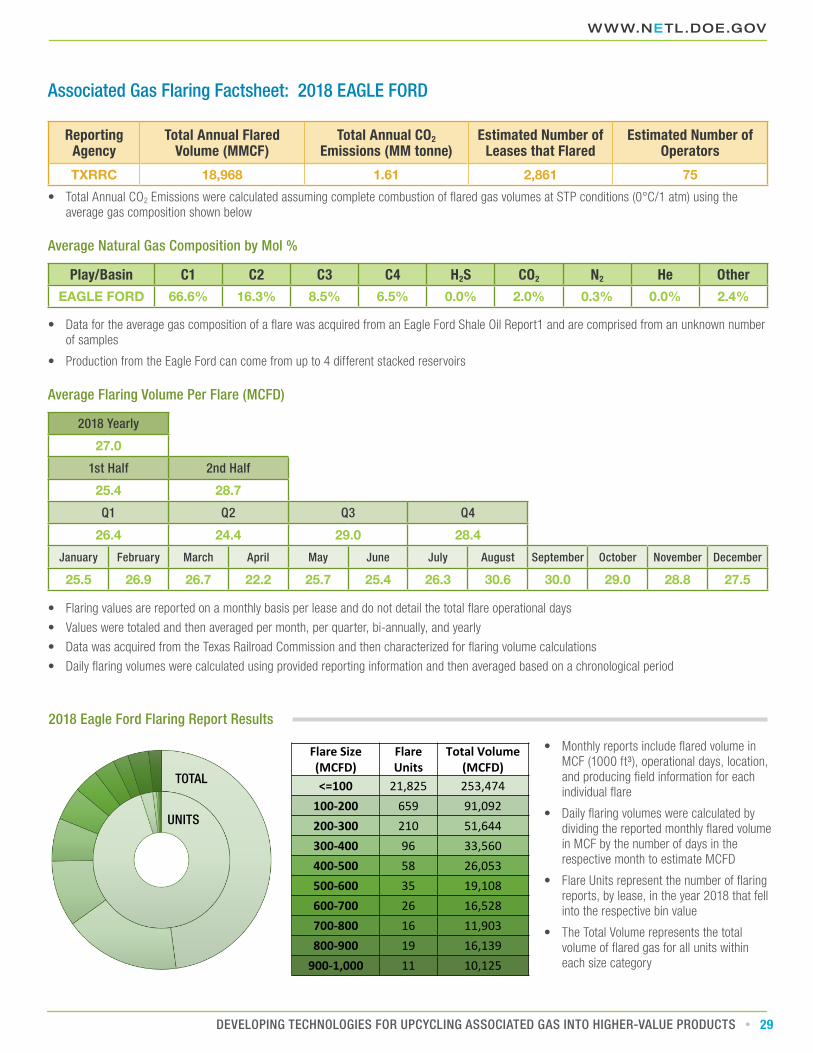
<=100 21,825 253,474100-200 659 91,092200-300 210 51,644300-400 96 33,560400-500 58 26,053500-600 35 19,108600-700 26 16,528700-800 16 11,903800-900 19 16,139
900-1,000 11 10,125
• Monthly reports include flared volume in MCF (1000 ft³), operational days, location, and producing field information for each individual flare
• Daily flaring volumes were calculated by dividing the reported monthly flared volume in MCF by the number of days in the respective month to estimate MCFD
• Flare Units represent the number of flaring reports, by lease, in the year 2018 that fell into the respective bin value
• The Total Volume represents the total volume of flared gas for all units within each size category
TOTAL
UNITS
2018 Eagle Ford Flaring Report Results
WWW.NETL.DOE.GOV
29DEVELOPING TECHNOLOGIES FOR UPCYCLING ASSOCIATED GAS INTO HIGHER-VALUE PRODUCTS
Associated Gas Flaring Factsheet: 2018 EAGLE FORD
Reporting Agency
Total Annual Flared Volume (MMCF)
Total Annual CO2 Emissions (MM tonne)
Estimated Number of Leases that Flared
Estimated Number of Operators
TXRRC 18,968 1.61 2,861 75
• Total Annual CO2 Emissions were calculated assuming complete combustion of flared gas volumes at STP conditions (0°C/1 atm) using the average gas composition shown below
Average Natural Gas Composition by Mol %
Play/Basin C1 C2 C3 C4 H2S CO2 N2 He OtherEAGLE FORD 66.6% 16.3% 8.5% 6.5% 0.0% 2.0% 0.3% 0.0% 2.4%
• Data for the average gas composition of a flare was acquired from an Eagle Ford Shale Oil Report1 and are comprised from an unknown number of samples
• Production from the Eagle Ford can come from up to 4 different stacked reservoirs
Average Flaring Volume Per Flare (MCFD)
2018 Yearly
27.0
1st Half 2nd Half
25.4 28.7
Q1 Q2 Q3 Q4
26.4 24.4 29.0 28.4
January February March April May June July August September October November December
25.5 26.9 26.7 22.2 25.7 25.4 26.3 30.6 30.0 29.0 28.8 27.5
• Flaring values are reported on a monthly basis per lease and do not detail the total flare operational days
• Values were totaled and then averaged per month, per quarter, bi-annually, and yearly
• Data was acquired from the Texas Railroad Commission and then characterized for flaring volume calculations
• Daily flaring volumes were calculated using provided reporting information and then averaged based on a chronological period

12.2020–1000
CONTACTJared Ciferno – Technology ManagerNational Energy Technology Laboratory