developing a project plan - nust
TRANSCRIPT

Developing a Project Plan
CHAPTER SIX
PowerPoint Presentation by Charlie Cook
Copyright © 2014 McGraw-Hill Education. All Rights Reserved.

6–2
Where We Are Now

6–3
Developing the Project Plan
• The Project Network– A flow chart that graphically depicts the sequence,
interdependencies, and start and finish times of the project job plan of activities that is the critical paththrough the network.
• Provides the basis for scheduling labor and equipment.• Enhances communication among project participants.• Provides an estimate of the project’s duration.• Provides a basis for budgeting cash flow.• Identifies activities that are critical.• Highlights activities that are “critical” and can not be delayed.• Help managers get and stay on plan.

6–4
WBS/Work Packages to Network
FIGURE 6.1

6–5
WBS/Work Package to Network (cont’d)
FIGURE 6.1 (cont’d)

6–6
Constructing a Project Network
• Terminology– Activity: an element of the
project that requires time.
– Merge Activity: an activity that has two or more preceding activities on which it depends.
– Parallel (Concurrent) Activities: Activities that can occur independently and, if desired, not at the same time.
A
C
DB

6–7
Constructing a Project Network (cont’d)
• Terminology– Path: a sequence of connected, dependent activities.
– Critical path: the longest path through the activity network that allows for the completion of all project-related activities; the shortest expected time in which the entire project can be completed. Delays on the critical path will delay completion of the entire project.
A B D
(Assumes that minimum of A + B > minimum of C in length of times to complete activities.)
C

6–8
Constructing a Project Network (cont’d)
• Terminology– Event: a point in time when an activity is started
or completed. It does not consume time.– Burst Activity: an activity that has more than one
activity immediately following it (more than one dependency arrow flowing from it).
• Two Approaches– Activity-on-Node (AON)
• Uses a node to depict an activity.– Activity-on-Arrow (AOA)
• Uses an arrow to depict an activity.
B
D
A C
6–9
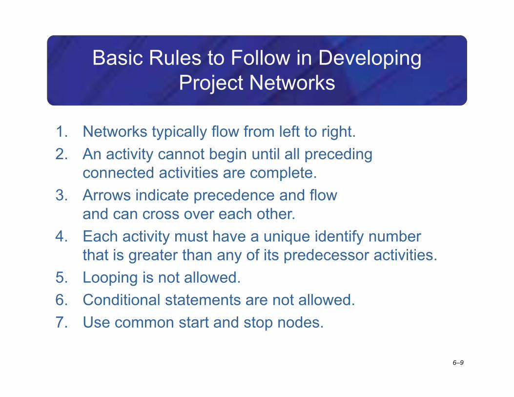
Basic Rules to Follow in Developing Project Networks
1. Networks typically flow from left to right.2. An activity cannot begin until all preceding
connected activities are complete.3. Arrows indicate precedence and flow
and can cross over each other.4. Each activity must have a unique identify number
that is greater than any of its predecessor activities.5. Looping is not allowed.6. Conditional statements are not allowed.7. Use common start and stop nodes.

6–10
Activity-on-Node Fundamentals
FIGURE 6.2

6–11
Activity-on-Node Fundamentals (cont’d)
FIGURE 6.2 (cont’d)

6–12
Network Information
TABLE 6.1

6–13
Automate Warehouse—Partial Network
FIGURE 6.3
6–14
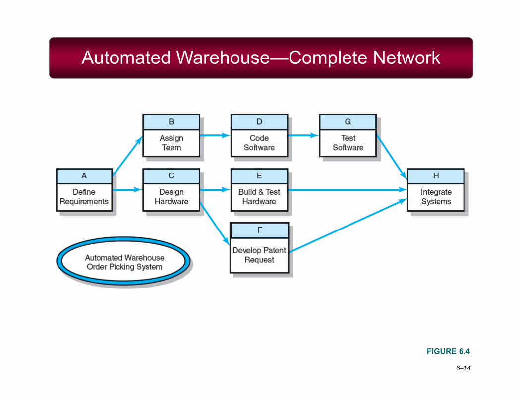
Automated Warehouse—Complete Network
FIGURE 6.4

6–15
Network Computation Process
• Forward Pass—Earliest Times– How soon can the activity start? (early start—ES)– How soon can the activity finish? (early finish—EF)– How soon can the project finish? (expected time—ET)
• Backward Pass—Latest Times– How late can the activity start? (late start—LS)– How late can the activity finish? (late finish—LF)– Which activities represent the critical path?– How long can activity be delayed? (slack or float—SL)

6–16
Network Information
TABLE 6.2

6–17
Activity-on-Node Network
FIGURE 6.5

6–18
Activity-on-Node Network Forward Pass
FIGURE 6.6

6–19
Forward Pass Computation
• Add activity times along each path in the network (ES + Duration = EF).
• Carry the early finish (EF) to the next activity where it becomes its early start (ES) unless…
• The next succeeding activity is a merge activity, in which case the largest EF of all preceding activities is selected.

6–20
Activity-on-Node Network Backward Pass
FIGURE 6.7

6–21
Backward Pass Computation
• Subtract activity times along each path in the network (LF - Duration = LS).
• Carry the late start (LS) to the next activity where it becomes its late finish (LF) unless
• The next succeeding activity is a burst activity, in which case the smallest LF of all preceding activities is selected.

6–22
Determining Free Slack (or Float)
• Free Slack (or Float)– Is the amount of time an activity can be delayed after
the start of a longer parallel activity or activities.– Is how long an activity can exceed its early finish date
without affecting early start dates of any successor(s).
– Allows flexibility in scheduling scarce resources.
• Sensitivity– The likelihood the original critical path(s) will change
once the project is initiated.– The critical path is the network path(s) that has
(have) the least slack in common.

6–23
Forward and Backward Passes Completed with Slack Times
FIGURE 6.8

6–24
Practical Considerations
• Network Logic Errors
• Activity Numbering
• Use of Computers to Develop Networks
• Calendar Dates
• Multiple Starts and Multiple Projects

6–25
Network Logic Errors: Illogical Loop
FIGURE 6.9
6–26
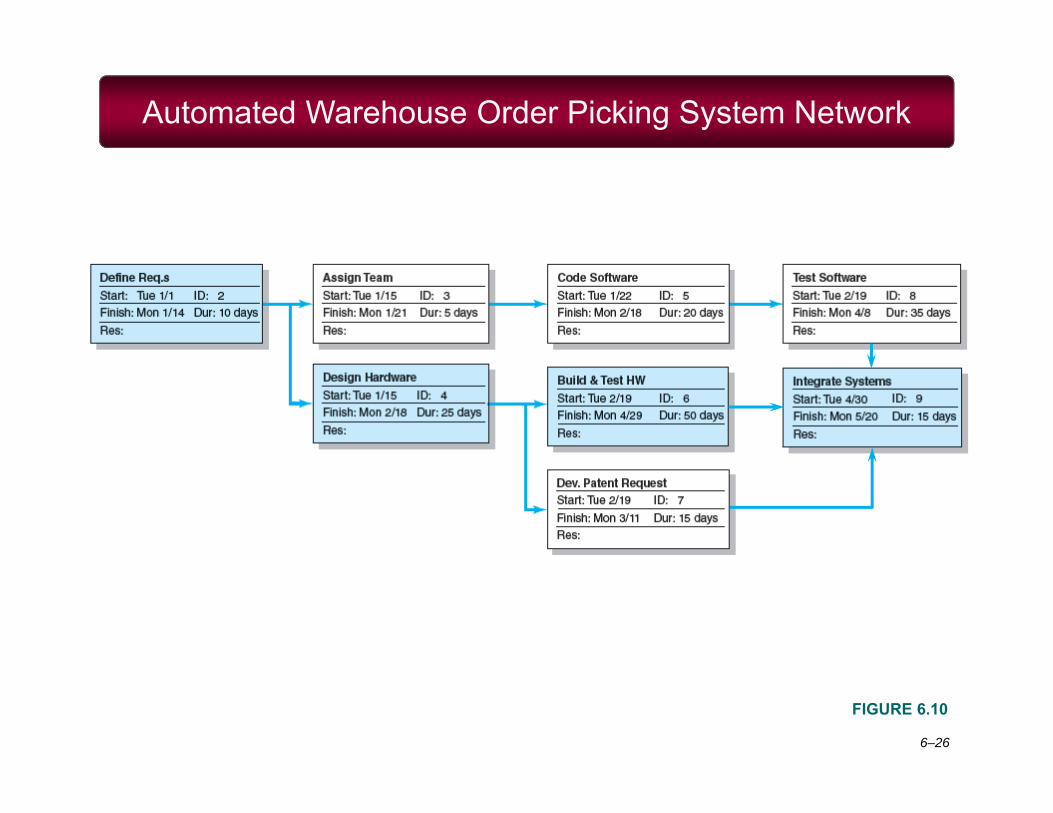
Automated Warehouse Order Picking System Network
FIGURE 6.10

6–27
Automated Order Warehouse Picking System Bar Chart
FIGURE 6.11
6–28
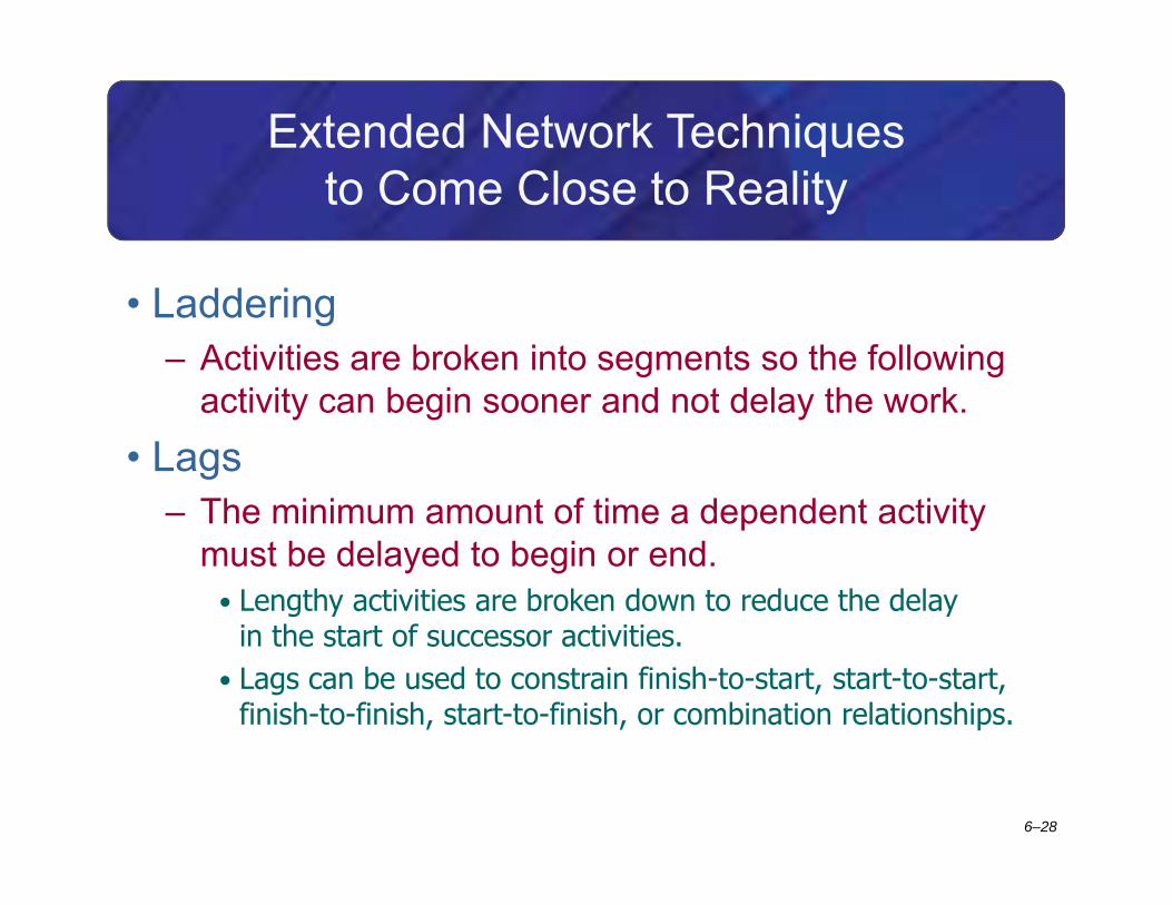
Extended Network Techniques to Come Close to Reality
• Laddering– Activities are broken into segments so the following
activity can begin sooner and not delay the work.• Lags
– The minimum amount of time a dependent activity must be delayed to begin or end.
• Lengthy activities are broken down to reduce the delay in the start of successor activities.
• Lags can be used to constrain finish-to-start, start-to-start, finish-to-finish, start-to-finish, or combination relationships.

6–29
Example of Laddering Using Finish-to-Start Relationship
FIGURE 6.12

6–30
Use of Lags
FIGURE 6.13
FIGURE 6.14
Finish-to-Start Relationship
Start-to-Start Relationship

6–31
Use of Lags Cont’d
FIGURE 6.15
Use of Lags to Reduce Project Duration

6–32
New Product Development Process
FIGURE 6.16

6–33
Use of Lags (cont’d)
FIGURE 6.17
FIGURE 6.18
FIGURE 6.19
Finish-to-Finish Relationship
Start-to-Finish Relationship
CombinationRelationship

6–34
Network Using Lags
FIGURE 6.20

6–35
Hammock Activities
• Hammock Activity– Spans over a segment of a project.
– Has a duration that is determined after the network plan is drawn.
– Is used to aggregate sections of the project to facilitate getting the right amount of detail for specific sections of a project.
– Is very useful in assigning and controlling indirect project costs.

6–36
Hammock Activity Example
FIGURE 6.21

6–37
Key Terms
ActivityActivity-on-arrow (AOA)Activity-on-node (AON)Burst activityConcurrent engineeringCritical pathEarly and late timesFree slack
Gantt chartHammock activityLag relationshipMerge activityParallel activitySensitivityTotal slack

6–38
Greendale Stadium Case
TABLE 6.3