developements in the simteche process-separation … in the simteche process – separation of co...
TRANSCRIPT

DEVELOPMENTS IN THE SIMTECHE PROCESS – SEPARATION OF CO2 FROM COAL SYNGAS BY FORMATION OF HYDRATES
Gordon Deppe1, S.S. Tam1, R.P. Currier2, J.S. Young2, G.K. Anderson2, L. Le2 and D.F. Spencer3
NEXANT, INC.
101 Second Street, San Francisco, CA 94105
2Los Alamos National Laboratory P.O. Box 1663 (MS J567), Los Alamos, NM 87545
3SIMTECHE
13474 Tierra Heights Road, Redding, CA 96003
1 INTRODUCTION Nexant, Inc., Los Alamos National Laboratory, and SIMTECHE are participating in an on-going R&D program to develop SIMTECHE's CO2 removal process. The program is sponsored by the US Department of Energy – National Energy Technology Laboratory, Michael Knaggs, project manager, Gary Stiegel product manager. The program is divided into four phases, ending in a pilot plant demonstration. Phase 1 was completed last year, and consisted of a proof-of-concept lab scale demonstration and an engineering analysis of the feasibility of the concept. Phase 2 is underway, consisting of further process development leading to the construction of a pilot plant.
Current technologies for CO2 removal use absorbent-solvents, recovering the CO2 with heat at lowered pressures. The SIMTECHE process removes CO2 from a shifted synthesis gas stream in an integrated gasification combined cycle (IGCC) plant by forming hydrates rich in CO2. The process avoids the use of large steam-reboiled regenerators, and produces high-pressure CO2 that reduces the cost of compression for sequestration.
AS DOE-FE continues to focus its R/DD and FutureGen Programs on the production of clean synthesis gas at high pressures and ultimately hydrogen from coal and other fossil fuels, the SIMTECHE CO2 hydrate separation process takes on added significance. This process shows great promise for providing the least expensive and most energy conserving process for separating CO2 from a high pressure, shifted synthesis gas stream. This paper will summarize the results of the experimental program conducted to date and update the economic analysis of the process.
A block flow diagram below shows the process concept. Coal syngas is cooled and fed to a reactor with water to form the hydrates. At the reactor conditions of roughly 1000 psia and 34ºF, only the CO2 and H2S in the syngas form hydrates. Heat evolved from the hydrate formation is removed with ammonia refrigerant. The solid hydrate and liquid water is separated from the syngas, which is suitable for final cleanup prior to being fed to a gas turbine or fuel cell. The water/hydrate slurry is decomposed, exchanging heat with condensing refrigerant, generating high-pressure CO2 for sequestration. Water is resaturated and recycled to the reactor.

The process doesn’t use large absorber towers or steam-reboiled regenerators, so both the capital and operating costs of the process are primarily in refrigeration compression. Some key process design parameters are:
Hydration number of the hydrate: the number of water molecules required per mole of CO2 removed has a large impact on the heat removal requirements in the reactor, and therefore the size of the refrigeration system.
Slurry Concentration: the amount of free water circulating in the system must be heated and cooled, this adds to the size of the refrigeration system
Temperature of the reactor: the performance of the system is greatly affected by temperature, both in CO2 removal and heat transfer.
2 THE STUDY 2.1 Experimental The experimental program includes collecting data on the equilibrium formation of CO2 hydrates and testing of the concept in continuous flow experiments. Equilibrium data includes the pressure-temperature hydrate formation limits of pure CO2 and mixtures of gases. The use of promoters to enhance the removal capabilities of the process was investigated. Flow experiments investigated the formation of hydrates in a continuous-flow apparatus, to demonstrate the ability to form hydrates continuously and begin to address operational issues.
2.2 Engineering Analysis Performance of the process is estimated using the experimental results to-date, preliminary equipment sizes generated and used for a factored cost estimate of a 500 MW IGCC commercial
2

power plant including CO2 control. The cost of carbon control is estimated and compared to conventional technologies.
3 EXPERIMENTAL 3.1 Equilibrium Experiments 3.1.1 Apparatus and Method A search of the literature revealed a lack of data on the phase boundaries in the H2-CO2-H2S-water system. This mixture corresponds to shifted synthesis gas and thus phase behavior data on this system was essential in establishing the equilibrium limits on the proposed process.
Figure 1: High pressure reactor from Parr Instruments for equilibrium experiments. Reactor volume is 600 ml. Mixing is achieved via a gas entrainment stirrer. A programmable chiller computer interfaced to a LabView software is used to control the reactor temperature. System temperature and pressure are also monitored using LabView.
The experimental measurements of the three-phase equilibrium conditions (aqueous liquid, vapor, and hydrate) were performed in a high-pressure cell using the isochoric method. Figure 1 illustrates the experimental apparatus. The high-pressure cell (Parr Instruments, Moline, IL) has a volume of 600 mL with removable glass liner inserts. Thorough mixing of the gas and liquid is achieved using a magnetically driven gas entrainment stirrer and baffle. The temperature of the system is controlled using a chiller whose setpoint is remotely controlled using LabView. The temperature and pressure of the system are also monitored using the same LabView software.
A number of experiments were performed with pure CO2 gas to verify performance of the experimental apparatus. The data was compared to data generated using a van der Waals-Platteeuw model developed at the Colorado School of Mines (E. Dendy Sloan, “Clathrate Hydrates of Natural Gases”, Second Edition, 1997, Marcel Dekker, Inc, New York, New York.) We chose to use the model for comparison because it is representative of the large set of accumulated literature data. The results showed excellent agreement between the model and the results from our experimental apparatus.
3

3.1.2 Results The key phenomenon enabling the separation of CO2 and H2S from the synthesis gas is the inability of H2 to be incorporated in the hydrate structure, a conclusion one would draw from the literature, but there was no experimental data for our particular system. Thus, after proving that our apparatus produces results comparable to those published in the literature, we wanted to show that H2 indeed does not form clathrates. Our approach was to perform an experiment using a mix of H2S and CO2, then to add H2 to the system, rerun the experiment and compare the two experimental results. Figure 2 illustrates the results. In Figure 2, the H2S/CO2 equilibrium line can be reproduced from the H2/H2S/CO2 experiment simply by subtracting the partial pressure of the H2 in the system. This type of experiment was repeated for several different pressure levels with the same result. We felt that this was sufficient evidence that H2 was not incorporated in the clathrate to any significant extent and did not alter the CO2-H2S equilibrium.
Carbon dioxide and hydrogen sulfide have quite different water-gas-hydrate phase equilibrium curves with the pure H2S clathrate forming at much lower pressures for a given temperature than the CO2 formation pressure. An interesting phenomenon in clathrate formation is the non-linear effect of the addition of the lower pressure hydrate former. In other words, the addition of a small amount of H2S to CO2, causes the equilibrium formation pressure of the mixed gas system to be quite a bit lower than that of pure CO2. Figure 3 illustrates this effect. The effect of H2S/CO2 composition on the equilibrium formation pressures was studied extensively to provide estimates of the separation capabilities of the process. Figure 4 is summary of the H2S/CO2 mixed gas experiments.
100
200
300
400
500
600
700
-5 0 5 10 15 20Temperature, °C
Pres
sure
, psi
a
Curve 1
Curve 2
Curve 3
100
200
300
400
500
600
700
-5 0 5 10 15 20Temperature, °C
Pres
sure
, psi
a
Curve 1
Curve 2
Curve 3
Figure 2: Curve 1 is the original mixed H2S/CO2 experiment. Curve 2 is the trace generated by adding H2 to the system to boost the pressure and rerunning the experiment. Curve 3 is the result of subtracting the partial pressure of the H2 from curve 2. The overlap of the equilibrium portions of curves 1 and 3 indicate no H2 clathrate formation occurs.
4

3/97 mol% H2S/CO2
150
200
250
300
350
400
-5 0 5 10 15 20 25
Temperature, °C
Pre
ssur
e, p
sia
Pure C O2 Phase Line
Figure 3 Equilibrium Experimental Data with a 3/97 mol% H2S/CO2 Mixture
H2S/CO 2
80
130
180
230
280
330
380
430
480
530
-4 -2 0 2 4 6 8 10 12
Temperature, ¡C
Pres
sure
, psi
a Pure CO21%3%5%10%
Figure 4 Measured hydrate formation pressure as a function of temperature
for various H2S percentages.
As shown in Figure 4, the equilibrium data also illustrate that the absolute partial pressure of H2S is an important controlling variable that can be exploited. With constant mole fractions of H2S and CO2 in a shifted synthesis gas stream, the partial pressure of H2S increases with increasing
5

total system pressure; thus the minimum hydrate formation pressure decreases. Generally, an increased system pressure should result in a greater separation of the hydrate formers from the gas stream.
Hydrate formation promoters other than H2S are being investigated in Phase 2. These include halocarbons, cyclic ethers and alkylonium salts.
3.2 Continuous-Flow Experiments The intent of the continuous-flow reactor (CFR) studies was to unambiguously establish that:
Large inductions times are not required for hydrate nucleation and growth
Hydrate slurry production can be sustained in a short residence time continuous flow apparatus
CO2 can be removed from a mixed gas stream as solid hydrates
The flow system experiments were done with pure CO2 feed to develop some process know-how, then with mixtures of Argon/CO2 to establish the removal ability of the concept. More recently, mixtures of Helium/CO2 have been run to establish the integrity of the apparatus before CO2/H2/H2S mixtures are run.
3.2.1 Apparatus A simplified flow schematic of the test system is shown below in figure 5. The mixed-gas test apparatus is shown, the pure CO2 flow system is essentially the same with a different feed source and no gas sampling. Mixed gases and conditioned water are metered to a reactor, which mixes the reactants. The reactants flow through a 3/16” ID tailtube where heat is removed in a jacket with circulating chilled glycol coolant. The hydrate slurry exits the tailtube and flows through a transparent section, for visual observation of the slurry. The slurry then flows into a separator. The water/hydrate slurry flows out the bottom into a sump, the gas flows overhead through a gas samplimg manifold and into the vent. System pressure is controlled by a backpressure regulator on the exit gas.
Water for feed was prepared by contact with gaseous CO2 until the gas pressure was roughly 180 psig, just under the pressure at which hydrates would form at 34ºF. The tank was immersed in a water/ice bath.
3.2.2 Results Residence times in the reactor/tail tube were in the range of 0.5-1 second (this represents only 1.5-3% of the residence time of the commercial-scale reactor). It was evident from heat transfer data, visual observations (and test run videos) made at the viewport that a slurry was exiting the tail tube.
However, it is was possible that the heat release could be partly due to water ice being formed. Tests were performed to verify that the material observed in the viewport was hydrates, not simply water ice. Two methods were used. First, the tests were run with system temperatures above 0oC, and slurry was still observed. The second tests consisted of collecting slurry in the separator, isolating the separator, and warming up above the temperature at which hydrates could
6

exist. The rise in pressure gave a convincing quantitative determination that the slurry was primarily CO2 hydrate.
Since there was evidence that, under some circumstances, hydrate may have been formed by depleting CO2 from the conditioned water, another uncertainty was introduced: the heat of hydrate formation. If the sole aqueous source of the CO2 is the conditioned water, there is no heat of solution required. The results from the mixed gas tests are reported with estimated hydrate production, the lower amount assuming that the heat of formation includes the heat of solution..
Mixed Gas Flow Tests - Conditioned Water Feed
Test No CO2 Feed H2O Feed Reactor Pressure
Coolant Feed Temp
Reaction Heat
Estimated Hydrate
Production Slurry Wt. % SR
Note 1 Note 1 Mole min Mole min Psig ºC Watt Mol/min
1 0.92 26 1033 -4 327 0.35-0.64 12-22 0.248 2 0.88 27 1046 -4 313 0.33-0.62 11-20 0.245 3 0.94 28 1017 -3 270 0.26-0.47 8-15 0.268 4 0.94 27 1028 -3 240 0.22-0.40 7-13 0.265 5 0.93 28 1002 -3 282 0.26-0.47 8-15 0.310 6 1.02 30 1012 -3 241 0.20-0.36 6-11 0.289
Avg 0.94 28 1023 -4 279 0.27-0.49 8-16 0.271 Notes: (1) Lower value in range uses a hydrate heat of formation of 63 kJ/mol, Hydration number of 6.3, mol. wt. of 157.4 g/mol. Higher value in range uses a hydrate heat of formation of 43 kJ/mol (same hydration number and mol. wt., assumes no heat of solution) By inspection, it is apparent that in some cases (the first three in the table) the production of hydrate was estimated to be larger than the amount of CO2 removed from the gas. This implies that some of the hydrate was formed from CO2 dissolved in the feed water, which in turn implies that the rate of hydrate formation was faster than the rate of CO2 removal from the gas phase.
In sum, the objectives of the phase 1 proof-of-concept were achieved.
4 ENGINEERING ANALYSIS An engineering analysis of the process was done, to determine the cost of carbon control for the SIMTECHE process and compare to typical conventional technologies. The Base case was a nominal 500MW coal gasifier, without any carbon capture.
The SIMTECHE process was integrated into an advanced IGCC plant. The Amine (DEA) alternative and the Selexol alternative were also integrated into an IGCC plant to compare the carbon control costs. The configuration of the alternatives assumed an equal CO2 removal percentage (64%) to the SIMTECHE process, since the cost of carbon control might be higher for higher removal percentages.
7

Sulfur removal is included for the total sulfur in the syngas (MDEA absorber with a Claus/SCOT plant). In all cases the CO2 is delivered at the battery limits at 2200 psig. A cost of electricity was generated for this base case.
The alternate cases divert much of the CO2 and H2S to sequestration, so the sulfur removal facilities are smaller. However, the lack of CO2 in the combustion gas results in a much larger amount of excess air in the gas turbine feed, to keep the temperature within the projected range of a near-term advanced gas turbine (2570 ºF). This, combined with the energy consumers in the CO2 scrubbing alternatives, result in lower net power generation. Assuming that the electricity is sold for the price calculated in the base case results in an operating deficit, which yields the cost of carbon control when divided by the total CO2 sequestered.
Table 2 shows a summary of the capital costs for the base case and three alternatives.
Table 2 Carbon Capture Alternatives Capital Costs
Basis: US Gulf Coast Case Base SIMTECHE Amine Selexol Coal Feed, Short Tons/Day 5,000 5,000 5,000 5,000 Carbon Dioxide Captured, Short Tons/Year* 0 1,821,269 1,821,269 1,821,269 Percentage Removal 0 64 64 64 Capital Cost, $millions, 2Q-2003
Gasifier/ASU 264.3 264.3 264.3 264.3 CO2 Removal 44.0 81.3 107.4
GT/Sulfur/BOP 370.4 335.8 335.8 332.9 Project Contingency 158.7 167.4 170.4 176.2
Total Capital Cost $millions 793.4 811.5 851.8 880.8 Added Capital Cost $millions Base 18.1 58.4 69.3 * Assuming a 75% Load Factor Using an 18% capital charge per year, and a 75% load factor, operating costs were developed and the cost of carbon control estimated. Table 3 shows the estimated carbon control costs.
8
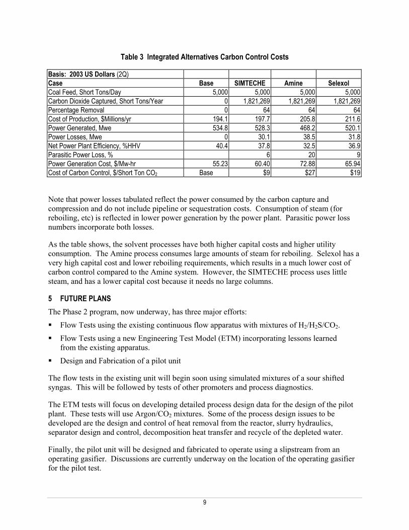
Table 3 Integrated Alternatives Carbon Control Costs
Basis: 2003 US Dollars (2Q) Case Base SIMTECHE Amine Selexol Coal Feed, Short Tons/Day 5,000 5,000 5,000 5,000 Carbon Dioxide Captured, Short Tons/Year 0 1,821,269 1,821,269 1,821,269 Percentage Removal 0 64 64 64 Cost of Production, $Millions/yr 194.1 197.7 205.8 211.6 Power Generated, Mwe 534.8 528.3 468.2 520.1 Power Losses, Mwe 0 30.1 38.5 31.8 Net Power Plant Efficiency, %HHV 40.4 37.8 32.5 36.9 Parasitic Power Loss, % 6 20 9 Power Generation Cost, $/Mw-hr 55.23 60.40 72.88 65.94 Cost of Carbon Control, $/Short Ton CO2 Base $9 $27 $19
Note that power losses tabulated reflect the power consumed by the carbon capture and compression and do not include pipeline or sequestration costs. Consumption of steam (for reboiling, etc) is reflected in lower power generation by the power plant. Parasitic power loss numbers incorporate both losses.
As the table shows, the solvent processes have both higher capital costs and higher utility consumption. The Amine process consumes large amounts of steam for reboiling. Selexol has a very high capital cost and lower reboiling requirements, which results in a much lower cost of carbon control compared to the Amine system. However, the SIMTECHE process uses little steam, and has a lower capital cost because it needs no large columns.
5 FUTURE PLANS The Phase 2 program, now underway, has three major efforts:
Flow Tests using the existing continuous flow apparatus with mixtures of H2/H2S/CO2.
Flow Tests using a new Engineering Test Model (ETM) incorporating lessons learned from the existing apparatus.
Design and Fabrication of a pilot unit
The flow tests in the existing unit will begin soon using simulated mixtures of a sour shifted syngas. This will be followed by tests of other promoters and process diagnostics.
The ETM tests will focus on developing detailed process design data for the design of the pilot plant. These tests will use Argon/CO2 mixtures. Some of the process design issues to be developed are the design and control of heat removal from the reactor, slurry hydraulics, separator design and control, decomposition heat transfer and recycle of the depleted water.
Finally, the pilot unit will be designed and fabricated to operate using a slipstream from an operating gasifier. Discussions are currently underway on the location of the operating gasifier for the pilot test.
9

Figure 5 Flow Test Schematic
10