determining the minimum mass and cost of a magnetic...
TRANSCRIPT

General rights Copyright and moral rights for the publications made accessible in the public portal are retained by the authors and/or other copyright owners and it is a condition of accessing publications that users recognise and abide by the legal requirements associated with these rights.
• Users may download and print one copy of any publication from the public portal for the purpose of private study or research. • You may not further distribute the material or use it for any profit-making activity or commercial gain • You may freely distribute the URL identifying the publication in the public portal
If you believe that this document breaches copyright please contact us providing details, and we will remove access to the work immediately and investigate your claim.
Downloaded from orbit.dtu.dk on: May 25, 2018
Determining the minimum mass and cost of a magnetic refrigerator
Bjørk, Rasmus; Smith, Anders; Bahl, Christian; Pryds, Nini
Published in:International Journal of Refrigeration
Link to article, DOI:10.1016/j.ijrefrig.2011.05.021
Publication date:2011
Link back to DTU Orbit
Citation (APA):Bjørk, R., Smith, A., Bahl, C. R. H., & Pryds, N. (2011). Determining the minimum mass and cost of a magneticrefrigerator. International Journal of Refrigeration, 34(8), 1805-1816. DOI: 10.1016/j.ijrefrig.2011.05.021

Published in International Journal of Refrigeration, Vol. 34 (8), 1805-1816, 2011DOI: 10.1016/j.ijrefrig.2011.05.021
Determining the minimum mass and cost of amagnetic refrigeratorR. Bjørk, A. Smith, C. R. H. Bahl and N. Pryds
AbstractAn expression is determined for the mass of the magnet and magnetocaloric material needed for a magneticrefrigerator and these are determined using numerical modeling for both parallel plate and packed sphere bedregenerators as function of temperature span and cooling power. As magnetocaloric material Gd or a modelmaterial with a constant adiabatic temperature change, representing a infinitely linearly graded refrigerationdevice, is used. For the magnet a maximum figure of merit magnet or a Halbach cylinder is used. For a cost of$40 and $20 per kg for the magnet and magnetocaloric material, respectively, the cheapest 100 W parallel platerefrigerator with a temperature span of 20 K using Gd and a Halbach magnet has 0.8 kg of magnet, 0.3 kg of Gdand a cost of $35. Using the constant material reduces this cost to $25. A packed sphere bed refrigerator withthe constant material costs $7. It is also shown that increasing the operation frequency reduces the cost. Finally,the lowest cost is also found as a function of the cost of the magnet and magnetocaloric material.
Department of Energy Conversion and Storage, Technical University of Denmark - DTU, Frederiksborgvej 399, DK-4000 Roskilde, Denmark*Corresponding author: [email protected]
1. IntroductionMagnetic refrigeration is a new environmentally friendly cool-ing technology with a potential for high energy efficiency.The technology is based on the magnetocaloric effect (MCE),which is the temperature change that most magnetic materialsexhibit when subjected to a changing magnetic field. For thebenchmark magnetocaloric material (MCM) used in magneticrefrigeration, gadolinium, the adiabatic temperature change isno more than 4 K in a magnetic field of 1 T [Dan’kov et al.,1998; Bjørk et al., 2010a], and therefore a magnetic refrigera-tion device has to utilize a regenerative process to produce alarge enough temperature span to be useful for refrigerationpurposes. The most utilized process for this is called activemagnetic regeneration (AMR) [Barclay, 1982].
An AMR consists of a porous matrix of a solid mag-netocaloric material and a heat transfer fluid that can flowthrough the matrix and reject or absorb heat. The solid matrixis termed the regenerator. The heat is then transferred to acold and hot heat exchanger at either end of the AMR. Usingthis system a temperature gradient can be built up that can bemuch larger than the adiabatic temperature change producedby the magnetocaloric material. Typically the porous matrixis either a packed sphere bed [Okamura et al., 2005; Tura andRowe, 2009] or consists of parallel plates [Zimm et al., 2007;Bahl et al., 2008]. A review of different magnetic refrigerationdevices is given in Yu et al. [2010].
The temperature span and cooling power generated by anAMR device depends on the process parameters specific toeach AMR system. These are the shape and packing of themagnetocaloric material, the temperature of the surroundingsand the properties of the MCM used, as well as the properties
of the heat transfer fluid, flow system, magnetic field, geome-try of the AMR etc. In operation, two performance parametersare of key importance, the temperature span, Tspan, which isthe difference between the temperature of the hot and the coldreservoir at either end of the AMR, Thot and Tcold, respectively,and the cooling power, Q, generated by the AMR. For givenprocess parameters, Tspan and Q trace out a curve called thecooling curve. In a (Tspan,Q) diagram the cooling curve is inmany cases of interest approximated by a straight line goingfrom (0, Qmax) to (Tspan,max,0) with a negative slope. As themaximum cooling power and the maximum temperature spancannot be realized at the same time, the operation point willlie on the cooling curve somewhere in between the two ex-trema. Neither extremity of the curve is of interest for actualoperation.
Determining the cost of an AMR is of general interest inorder to evaluate the cost-performance of the technology. Anassessment of the costs for a residential air conditioner basedon magnetic cooling presented in Russek and Zimm [2006]concluded that the cost of the magnet is of great importanceand furthermore found that the cost of the magnet and mag-netocaloric material for such a magnetic air conditioner canbe competitive with conventional air conditioners. It has alsobeen investigated [Egolf et al., 2007] whether magnetic heatpumps can compete with conventional heat pumps. Based onsimple theoretical calculations it is estimated that magneticheat pumps are only 30% more expensive than conventionalheat pumps. However, the price of the magnet is never con-sidered in this analysis. The total cost of a AMR magneticrefrigeration device has recently been considered in Rowe[2009] and Rowe [2011] who defined a general performance

Determining the minimum mass and cost of a magnetic refrigerator — 2/12
metric for active magnetic regenerators. The cost and effec-tiveness of the magnet design is included in this metric as alinear function of the volume of the magnet, and the gener-ated field and the amount of magnetocaloric material usedis also included in the metric. However, the metric has tobe calculated for a specific refrigeration system and can notbe used to predict the general performance per dollar of themagnetic refrigeration technology. A figure of merit used toevaluate the efficiency of a magnet design used in magneticrefrigeration has been introduced in Bjørk et al. [2008] butthis does not take the performance of the actual AMR systeminto account.
Here, we are interested in determining the lowest com-bined cost of magnet and magnetocaloric material needed fora magnetic refrigerator as a function of a desired temperaturespan and cooling power. Determining the lowest combinedcost of magnet and magnetocaloric material allows for thedetermination of the major source of cost of a magnetic refrig-eration device and thus allows the technology to be comparedto competing refrigeration technologies. Note that we wishto determine the lowest combined cost, i.e. the cost of thematerials for the cheapest magnetic refrigerator. Thus when-ever a cost is given in this article it is the cost of the materialsneeded to construct the device that is meant. It is important tostate that the cheapest system might not be the most efficientdevice possible, i.e. the device that has the highest coefficientof performance (COP). However, such a device would usemore magnet and magnetocaloric material than the lowest costdevice. The overall lifetime cost of a magnetic refrigerationdevice include both capital cost and operating cost but this isnot considered in the present analysis.
2. Determining the mass of the magnet
A magnetic refrigerator in which the magnetic field is pro-vided by a permanent magnet assembly, as is the case foralmost all magnetic refrigeration devices [Bjørk et al., 2010b],is considered. A measure of the efficiency of a magnet usedin magnetic refrigeration is given by the Λcool parameter, asdefined in Bjørk et al. [2008]. The Λcool parameter is definedas
Λcool ≡(〈B2/3〉−〈B2/3
out 〉)Vfield
VmagPfield , (1)
where Vmag is the volume of the magnet(s), Vfield is the volumewhere a high flux density is generated, Pfield is the fraction ofan AMR cycle that magnetocaloric material is placed in thehigh flux density volume, 〈B2/3〉 is the volume average of theflux density in the high flux density volume to the power of2/3 and 〈B2/3
out 〉 is the volume average of the flux density to thepower of 2/3 in the volume where the magnetocaloric materialis placed when it is being demagnetized. Note that it is themagnetic flux density generated in an empty volume that isconsidered, i.e. B = µ0H, and thus it is equivalent to speak ofthe magnetic flux density or the magnetic field.
A high Λcool generally favors small magnetic fields. How-ever, this decreases the rate of heat transfer between the mag-netocaloric material and the heat transfer fluid, ultimatelydecreasing the performance of the device. The optimum mag-net configuration will reflect a trade-off between high magnetefficiency and high rates of heat transfer. This, in turn, will de-pend on the detailed configuration of the device. A number ofmagnet arrays for magnetic refrigeration have been comparedin Bjørk et al. [2010b].
An alternative way to classify permanent magnet arrays isto consider the so-called figure of merit, M∗, which is definedas [Jensen and Abele, 1996]
M∗ =
∫Vfield||µ0H||2dV∫
Vmag||Brem||2dV
(2)
where Vfield is the volume of the air gap where the desiredmagnetic field, µ0H, is created and Vmag is the volume ofthe magnets which have a remanence Brem. For isotropicmaterials with linear demagnetization characteristics this is ameasure of the magnetic field energy in the air gap, dividedby the maximum amount of magnetic energy available inthe magnet material. Although magnet arrays with a highvalue of M∗ are not necessarily good magnets for magneticrefrigeration, M∗ offers a succinct way of characterizing thefield strength attained in the high field region. It has the addedadvantage that an upper bound is known: It can be shown thatthe maximum value of M∗ is 0.25. Here such a magnet willbe termed the M25 magnet. For the remainder of this paper wewill characterize the magnet array using the figure of merit.
For specific permanent assemblies it is possible to calcu-late M∗ analytically; this will be considered later. Further-more, if we limit ourselves to three-dimensional structureswith a constant magnitude of the remanence (whose directionis allowed to vary) which generate a constant magnetic fieldin the gap, Eq. (2) can be rewritten as
M∗ =(
µ0HBrem
)2 Vfield
Vmag. (3)
Rearranging this equation by substituting the volume ofthe high field region for the mass of magnetocaloric material,mmcm,field, divided by the mass density of the MCM, ρmcm,times one minus the porosity of the regenerator (includingsupport structure), (1− ε), and substituting the volume ofthe magnet by the mass, mmag, divided by the density, ρmag,yields
mmag =
(µ0HBrem
)2 mmcm,fieldρmag
(1− ε)ρmcmM∗. (4)
All terms that are a function of the magnetic field are on oneside of the equation and thus from this equation we can calcu-late the mass of the magnet needed for a magnetic refrigerator,if we know the mass of magnetocaloric material as a func-tion of µ0H required to provide the desired temperature span,Tspan, and cooling power, Q. Also, M∗ as a function of µ0Hmust of course also be known.
Determining the minimum mass and cost of a magnetic refrigerator — 3/12
Note that the masses that are related in Eq. (4) are themass of the magnet and the mass of magnetocaloric materialthat is placed inside the magnet during an AMR cycle. If ansymmetric AMR cycle and only a single regenerator is usedthe magnet will only be in use half of the cycle time, which isvery inefficient. However, if one uses two regenerators, runcompletely out of phase and using the same magnet, doublethe amount of cooling power will be produced, of course usingdouble the amount of magnetocaloric material but using thesame amount of magnet. This system, in which the magnet isutilized at all times, is the most efficient system possible, andthus allows for a modification of Eq. (4) such that
mmag =12
(µ0HBrem
)2 mmcmρmag
(1− ε)ρmcmM∗. (5)
where mmcm is now the total amount of magnetocaloric ma-terial, and it is assumed that the magnet is in use, i.e. filledwith magnetocaloric material with a mass of mmcm/2, at alltimes. AMR devices in which the magnet is in use almostcontinuously have previously been demonstrated [Tusek et al.,2010; Bjørk et al., 2010c]. Such an AMR which uses themagnet at all times is what is considered in the following.
As an example assume that the densities of the magne-tocaloric material and the magnet are identical and that thesystem has a porosity of 0.5. Also, consider a magnetic fieldwith the value of the remanence. For the magnet with thelargest possible figure of merit, M∗ = 0.25, i.e. the M25 mag-net, we obtain from Eq. (5) that the mass of the magnet mustbe four times the mass of magnetocaloric material used ifthe magnet is used at all times. If only a single regeneratorwas used then the mass of the magnet would be eight timesthat of the magnetocaloric material. However, for specificregenerator geometries and magnetocaloric material the massof the magnet can be calculated more precisely.
3. Determining the minimum mass ofmagnetocaloric material
In order to use Eq. (5) to calculate the cost of a magnetic refrig-eration system we need to know the mass of magnetocaloricmaterial as function of µ0H required to provide the desiredtemperature span, Tspan, and cooling power, Q. In order to de-termine this a parameter survey has been conducted where thecooling power has been computed using a numerical model fortwo different magnetic refrigeration devices, both using Gdmodeled using the mean field theory (MFT) [Morrish, 1965].The model used is a publicly available one-dimensional nu-merical model [Engelbrecht et al., 2006]. By varying theNusselt-Reynolds correlations the model is capable of model-ing both packed bed and parallel plate regenerators. For bothregenerator geometries the model has previously been com-pared with both experimental data and other numerical models[Engelbrecht, 2008; Petersen et al., 2008a; Bahl et al., 2008].In the numerical model, the temperature span is an input pa-rameter and the cooling power is calculated for the specified
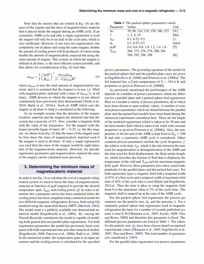
Table 1. The packed sphere parameters varied.Parameter Values Unit∆x 70, 90, 110, 135, 150, 180, 215 [%]f 1, 2, 4, 10 [Hz]τrel 0.1, 0.25, 0.5 [-]dp 0.1, 0.25, 0.5 [mm]µ0H 0.4, 0.6, 0.8, 1.0, 1.2, 1.4, 1.6 [T]Tcold 268, 272, 276, 278, 280, 284
288, 292, 296, 298 [K]
process parameters. The governing equations of the model forthe packed sphere bed and the parallel plate cases are givenin Engelbrecht et al. [2006] and Petersen et al. [2008a]. TheGd material has a Curie temperature of Tc = 293.6 K andproperties as given in Petersen et al. [2008b].
As previously mentioned the performance of the AMRdepends on a number of process parameters, which are differ-ent for a parallel plate and a packed sphere bed regenerator.Here we consider a variety of process parameters, all of whichhave been chosen to span realistic values. A number of com-mon process parameters which are shared between the parallelplate and the packed bed models have been fixed during thenumerical experiments considered here. These are the lengthof the modeled regenerator which is taken to be 50 mm andthe heat transfer fluid which is taken to be water with constantproperties as given in Petersen et al. [2008a]. Also, the tem-perature of the hot end of the AMR is kept fixed at Thot = 298K and only a symmetric AMR cycle is considered. Othercommon process parameters include the cycle frequency, f ,the relative cycle time, τrel, which is the ratio between the timeused for magnetization or demagnetization of the AMR andthe time used for fluid displacement, the fluid stroke length,∆x, which describes the fraction of fluid that is displaced, thetemperature of the cold end, Tcold and the maximum magneticfield, µ0H. However, these parameters have been varied inde-pendently for the parallel plates and the packed bed cases. Forboth regenerator types a magnetic field with a temporal widthof 55% of a flow cycle and a temporal width of maximum fieldtime of 45% of the cycle time is used [Bjørk and Engelbrecht,2011a]. Thus the time it takes to ramp the magnetic fieldfrom 0 to the maximum value is 5% of the cycle time. Themagnetic field is ramped up at the start of the AMR cycle.
For the packed sphere bed regenerator the process pa-rameters are the particle size, dp, and the porosity, ε . For arandomly packed sphere bed regenerator used in magneticrefrigeration the latter for a number of recently published sys-tems is near 0.36 [Okamura et al., 2005; Jacobs, 2009; Turaand Rowe, 2009] and therefore this parameter is fixed. Thedifferent process parameters are listed in Table 1. The valuesfor the particle size, dp, have been chosen based on reportedexperimental values [Okamura et al., 2005; Engelbrecht et al.,2007; Tura and Rowe, 2009]. The total number of parametersets considered is 15876.
For the parallel plate regenerator two process parameters

Determining the minimum mass and cost of a magnetic refrigerator — 4/12
Table 2. The parallel plate parameters varied.Parameter Values Unit∆x 40, 50, 60, 70, 80, 90 [%]f 0.167, 0.33, 1, 2, 4 [Hz]τrel 0.25, 0.50 [-]hfluid 0.1, 0.25, 0.5 [mm]hplate 0.1, 0.25, 0.5 [mm]µ0H 0.4, 0.6, 0.8, 1.0, 1.2, 1.4, 1.6 [T]Tcold 268, 273, 278, 283, 288, 293, 298 [K]
must be specified. These are the height of the fluid channel,hfluid, and the height of the plate, hplate. These have beenchosen based on realistic experimental values [Bahl et al.,2008; Engelbrecht et al., 2010]. The different process pa-rameters considered for the parallel plate case are listed inTable 2. However, for the parallel plate regenerator modela comparison with a two-dimensional AMR model leads tothe requirement that a “1D correctness” parameter, Γ, mustbe much greater than one for the one-dimensional model toproduce comparable results to a two-dimensional model [Pe-tersen et al., 2008a]. Here all process parameters with Γ < 3will not be considered further. These are process parameterswith large values of hfluid and large values of f . Therefore thetotal number of parameter sets considered is 14994.
For each of the set of process parameters the coolingpower is calculated. Using this data, the mass of magne-tocaloric material can be directly determined as a functionof µ0H for a desired Q and Tspan by only assuming that thecooling power is directly proportional to the mass of magne-tocaloric material. For each temperature span and magneticfield the combined cost of the magnet and the MCM is simplycalculated using Eq. (5) for all process parameters and thelowest cost selected. In the following we take the cost of themagnet material to be $40 per kg and the cost for the magne-tocaloric material to be $20 per kg, similarly to Rowe [2011].The cost of assembly of the magnet and the regenerator isnot included; although these costs may be substantial for theinitial market entry devices, for a mass-produced product theyare expected to be relatively minor. Differing cost estimatesfor the materials will be discussed subsequently. Using thesenumbers the total cost is calculated by adding the cost ofthe magnet and magnetocaloric material and minimizing thisvalue for all process parameters. Note that, as argued previ-ously, substantially more magnet compared to magnetocaloricmaterial must be used. Therefore the calculation of the totalcost is not very sensitive to the cost of the magnetocaloricmaterial, but will scale roughly linearly with the cost of themagnet material.
4. Cost of a Gd AMRIn order to determine the lowest combined cost of magnet andmagnetocaloric material needed to produce a given desiredtemperature span and cooling power certain parameters must
µ0H/B
rem
M*
0.5 1 1.5 2 2.50
0.05
0.1
0.15
0.2 1.6 2.7 4.5 7.4 12.2
ro/r
i
Figure 1. The figure of merit, M∗, as a function of magneticfield in units of the remanence for a Halbach cylinder ofinfinite length.
be specified. Here, we consider magnets with a remanence of1.2 T, which is a common value for NdFeB magnets, whichare the most powerful magnets commercially available today.These have a density of ρmag = 7400 kg/m3. The density of Gdis ρmcm = 7900 kg/m3. For the parallel plate regenerators theporosity of the regenerator is calculated as ε = hfluid/(hfluid +hplate), while for the packed sphere bed the porosity is constantat ε = 0.36. Note that none of these values for the porosityincludes any support or housing structure for the regenerator.
As previously mentioned for an M25 magnet the figure ofmerit is M∗ = 0.25 for all values of µ0H. However, we willalso consider the Halbach cylinder [Mallinson, 1973; Halbach,1980] which is a magnet design that has previously been usedextensively in magnetic refrigeration devices [Lu et al., 2005;Tura and Rowe, 2007; Engelbrecht et al., 2009; Kim andJeong, 2009]. For this magnet design the efficiency parametercan be found analytically for a cylinder of infinite length,through the relation for the field in the cylinder bore, µ0H =
Bremln(
rori
), where ri and ro are the inner and outer radius
of the Halbach cylinder, respectively. Using this relation onegets [Coey and Ni Mhiochain, 2003]
M∗ =ln(
rori
)2
(rori
)2−1
=
(µ0HBrem
)2
e2 µ0HBrem −1
. (6)
This function is shown in Fig. 1 and has an optimal value ofM∗ ≈ 0.162 for a value of µ0H/Brem ≈ 0.80. For a Halbachof finite length the efficiency is lowered, depending on thelength and inner radius of the device [Bjørk, 2011b]. Here,for simplicity, we will only consider a Halbach cylinder ofinfinite length.

Determining the minimum mass and cost of a magnetic refrigerator — 5/12
(a) a
(b) b
Figure 2. The minimum cost in $ of a parallel plate magneticrefrigeration system of Gd as a function of temperature spanand cooling power for (a) a M25 permanent magnet assemblyand (b) a Halbach cylinder of infinite length.
4.1 A parallel plate regenerator of GdWe begin by analyzing the cost of a parallel plate regeneratorof Gd, as this is the benchmark system in magnetic refrigera-tion. Using the approach described above the total minimumcombined cost of a parallel plate Gd regenerator with an M25magnet as a function of desired temperature span and coolingpower of the AMR is shown in Fig. 2a while for a Halbachmagnet the minimum cost is shown in Fig. 2b for the processparameters considered here. The corresponding amount ofmagnet material, magnetocaloric material and magnetic fieldfor the minimum cost device using a Halbach magnet areshown in Fig. 3. Here we are only interested in determiningthe minimum cost of a magnetic refrigeration device, and thusthe process parameters for the lowest cost device will not beanalyzed.
From Fig. 2 we see that the cost of a refrigeration systemincreases with both temperature span and cooling power andthat a device using a Halbach cylinder is ∼ 25−50% moreexpensive than when an M25 magnet is used. For examplea system that produces 100 W of continuous cooling at atemperature span of 20 K using a Halbach magnet will have aminimum cost of $35.
In Fig. 3 we see that increasing the desired cooling powerand temperature span increases the amount of magnet thatmust be used, as expected. It is also seen that the magneticfield is constant as a function of cooling power while it in-creases monotonically with temperature span. The reason forthis behavior is that the only way to increase the temperaturespan is to increase the magnetic field as Tspan does not dependon mmcm. Also, note that even for very low temperature spansa magnetic field above 0.6 T is favored. This is because theM∗ parameter for a Halbach cylinder drops off significantlyat low magnetic fields as shown in Fig. 1. This is not the casefor the M25 magnet, where low magnetic fields are favored.From the figure we also see that the amount of magnetocaloricmaterial increases with cooling power, especially for a highvalue of the temperature span. This can be explained basedon Eq. (6) which shows that it is too expensive to generatea strong magnetic field and thus it is more favorable to usemore magnet material to generate a large cooling power. Fi-nally, note that about two to three times more magnet thanmagnetocaloric material is used. Therefore the total cost willbe roughly proportional to the cost of the magnet.
4.2 A packed sphere bed regenerator of GdHaving considered the cost of the parallel plate regeneratorwe now consider the packed sphere bed regenerator. In Fig.4 the minimum combined cost of a packed sphere bed regen-erator of Gd and using either an M25 or a Halbach magnet isshown. From this figure we see that the total minimum cost ofa packed sphere bed regenerator is several times less than thatof a parallel plate regenerator. As for the parallel plate casechanging from an M25 magnet to a Halbach cylinder increasesthe cost by up to ∼ 50%. Note that we do not consider theCOP, i.e. the cost of operating the magnetic refrigerators, butonly the cost of the materials for the devices. So althoughpacked sphere beds are better than the parallel plates the en-ergy needed for operation may be higher due to the increasedpressure loss.
In Fig. 5 the corresponding amount of magnetocaloricmaterial, magnetic field and magnet material for the minimumcombined cost packed sphere bed AMR with Gd and usinga Halbach magnet, i.e. the cost shown in Fig. 4b, is plot-ted. Compared to the parallel plate case (see Fig. 3) we seethat both the amount of magnet and magnetocaloric materialneeded has been greatly reduced, which explains the signif-icant reduction in the overall cost of the system. Otherwise,the amount of magnetocaloric material and the value of themagnetic field follow the same trends as seen for the parallelplate case.

Determining the minimum mass and cost of a magnetic refrigerator — 6/12
(a) a
(b) b
(c) c
Figure 3. (a) The amount of magnet material, (b) thecorresponding amount of magnetocaloric material and (c) thecorresponding magnetic field for the parallel plate magneticrefrigeration system using Gd with the lowest combined costof the magnet and magnetocaloric material for a Halbachcylinder of infinite length, i.e. with M∗ given by Eq. (6).
(a) a
(b) b
Figure 4. The minimum cost in $ of a packed sphere bedmagnetic refrigeration system of Gd as a function oftemperature span and cooling power of an AMR for (a) a M25permanent magnet assembly and (b) a Halbach cylinder ofinfinite length.

Determining the minimum mass and cost of a magnetic refrigerator — 7/12
5. A graded magnetocaloric materialIt has previously been shown that a gain in cooling power canbe obtained by using several magnetocaloric materials withdifferent Curie temperatures in a so called multimaterial AMRsystem [Rowe and Tura, 2006; Jacobs, 2009; Nielsen et al.,2010; Hirano et al., 2010; Russek et al., 2010]. Therefore thecost of a multimaterial AMR will also be considered.
Here we consider a material with a constant ∆Tad profileas function of temperature. Such a material can be thoughtof as representing an infinitely linearly graded AMR for agiven temperature span in a AMR operating at steady state.The adiabatic temperature change is chosen to be equal tothe peak adiabatic temperature change for commercial gradeGd as reported in Bjørk et al. [2010a], which is ∆Tad = 3.3K. The specific heat capacity as a function of temperaturein zero applied magnetic field is taken to be constant with avalue of cp = 270.36 J kg−1 K−1, which is the average of themeasured value of cp for commercial grade Gd in the tem-perature interval from 220 K to 340 K as reported in Bjørket al. [2010a]. Then the remaining magnetocaloric proper-ties for this material, e.g. the specific heat capacity as afunction of magnetic field, are constructed in a thermodynam-ically consistent way as described in Engelbrecht and Bahl[2010]. Finally the adiabatic temperature change is chosento scale as a power law with an exponent of 2/3 for all tem-peratures, i.e. ∆Tad(µ0H) = ∆Tad(1 T)(µ0H)2/3. This is thetheoretical scaling of a second order material calculated us-ing mean field theory at the Curie temperature [Oesterreicherand Parker, 1984] and it has been observed for both Gd andLaFe13−x−yCoxSiy materials [Pecharsky and Gschneidner Jr,2006; Bjørk et al., 2010a]. As the material with the constantadiabatic temperature change is always operating at the Curietemperature the 2/3 power law scaling is assumed to be truefor all temperatures. The remaining material properties aretaken to be identical to Gd.
The cooling power has been computed for all processparameters given in Table 1 and 2, as for Gd. Shown in Fig. 6is the minimum combined cost for a magnetic refrigerationsystem using the constant ∆Tad material, for both an M25 anda Halbach magnet. Compared to the device using Gd (seeFig. 2) it is seen that using a material with constant ∆Tadcan optimally reduce the cost of the refrigeration device by50%. The same conclusions apply to Fig. 7 which shows theminimum combined cost for the packed bed system using aconstant ∆Tad material.
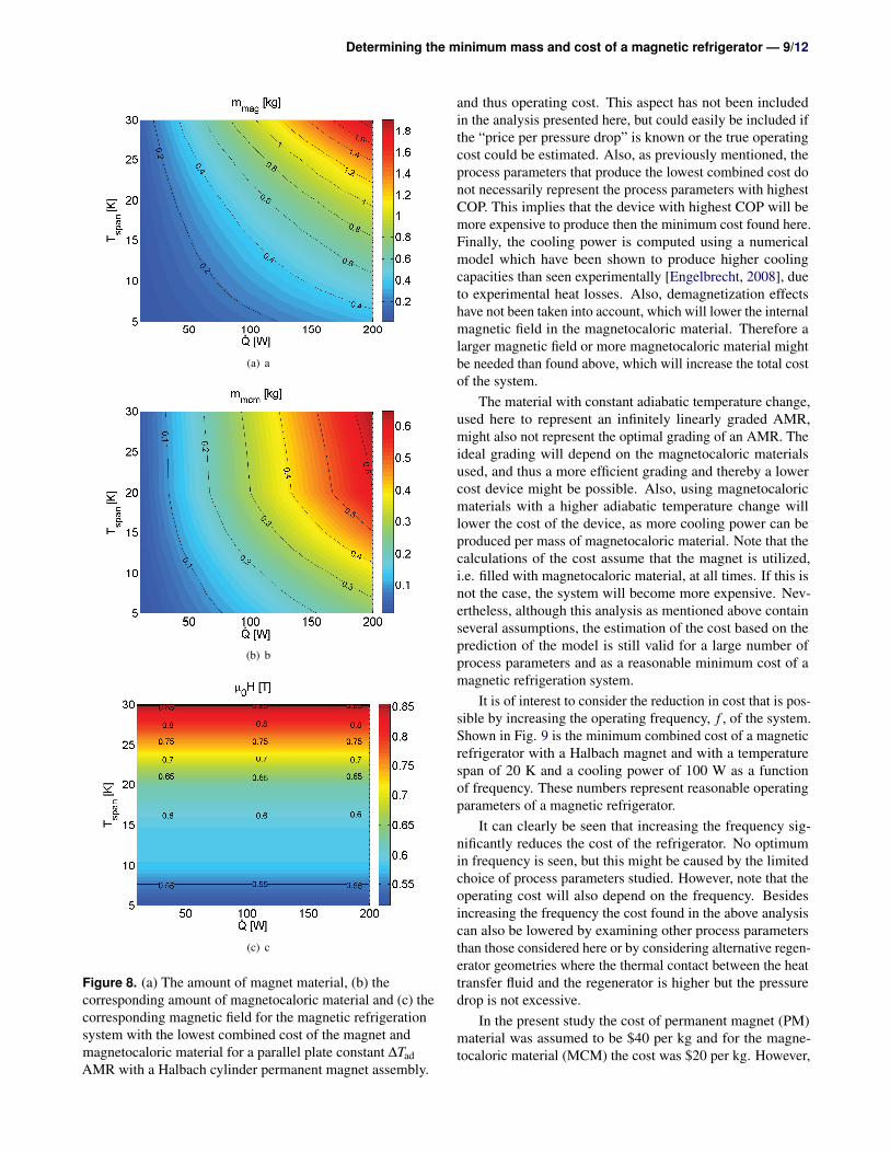
Shown in Fig. 8 is the corresponding amount of magne-tocaloric material, magnetic field and magnet material for theminimum combined cost parallel plate AMR with a constant∆Tad material and using a Halbach magnet, cf. Fig. 6b. Com-pared to Fig. 3 the amount of magnet material needed hasbeen halved, which is also the reason for the overall reduc-tion in cost. Even though the cooling power of the constant∆Tad material for most temperatures is higher than for Gd itis seen that the same amount of magnetocaloric material isused in the AMR. However, the value of the magnetic field
(a) a
(b) b
(c) c
Figure 5. (a) The amount of magnet material, (b) thecorresponding amount of magnetocaloric material and (c) thecorresponding magnetic field for the magnetic refrigerationsystem with the lowest combined cost of the magnet andmagnetocaloric material for a packed bed AMR with Gd anda Halbach cylinder permanent magnet assembly.
Determining the minimum mass and cost of a magnetic refrigerator — 8/12
(a) a (b) b
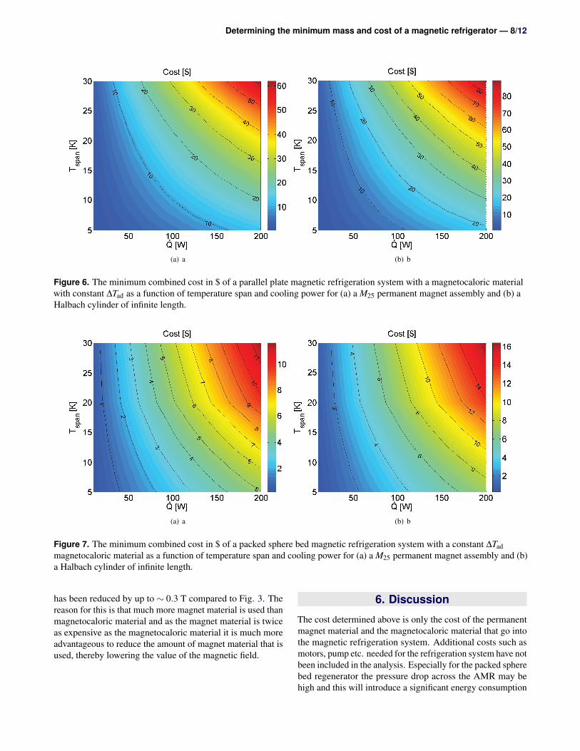
Figure 6. The minimum combined cost in $ of a parallel plate magnetic refrigeration system with a magnetocaloric materialwith constant ∆Tad as a function of temperature span and cooling power for (a) a M25 permanent magnet assembly and (b) aHalbach cylinder of infinite length.
(a) a (b) b
Figure 7. The minimum combined cost in $ of a packed sphere bed magnetic refrigeration system with a constant ∆Tadmagnetocaloric material as a function of temperature span and cooling power for (a) a M25 permanent magnet assembly and (b)a Halbach cylinder of infinite length.
has been reduced by up to ∼ 0.3 T compared to Fig. 3. Thereason for this is that much more magnet material is used thanmagnetocaloric material and as the magnet material is twiceas expensive as the magnetocaloric material it is much moreadvantageous to reduce the amount of magnet material that isused, thereby lowering the value of the magnetic field.
6. Discussion
The cost determined above is only the cost of the permanentmagnet material and the magnetocaloric material that go intothe magnetic refrigeration system. Additional costs such asmotors, pump etc. needed for the refrigeration system have notbeen included in the analysis. Especially for the packed spherebed regenerator the pressure drop across the AMR may behigh and this will introduce a significant energy consumption
Determining the minimum mass and cost of a magnetic refrigerator — 9/12
(a) a
(b) b
(c) c
Figure 8. (a) The amount of magnet material, (b) thecorresponding amount of magnetocaloric material and (c) thecorresponding magnetic field for the magnetic refrigerationsystem with the lowest combined cost of the magnet andmagnetocaloric material for a parallel plate constant ∆TadAMR with a Halbach cylinder permanent magnet assembly.
and thus operating cost. This aspect has not been includedin the analysis presented here, but could easily be included ifthe “price per pressure drop” is known or the true operatingcost could be estimated. Also, as previously mentioned, theprocess parameters that produce the lowest combined cost donot necessarily represent the process parameters with highestCOP. This implies that the device with highest COP will bemore expensive to produce then the minimum cost found here.Finally, the cooling power is computed using a numericalmodel which have been shown to produce higher coolingcapacities than seen experimentally [Engelbrecht, 2008], dueto experimental heat losses. Also, demagnetization effectshave not been taken into account, which will lower the internalmagnetic field in the magnetocaloric material. Therefore alarger magnetic field or more magnetocaloric material mightbe needed than found above, which will increase the total costof the system.
The material with constant adiabatic temperature change,used here to represent an infinitely linearly graded AMR,might also not represent the optimal grading of an AMR. Theideal grading will depend on the magnetocaloric materialsused, and thus a more efficient grading and thereby a lowercost device might be possible. Also, using magnetocaloricmaterials with a higher adiabatic temperature change willlower the cost of the device, as more cooling power can beproduced per mass of magnetocaloric material. Note that thecalculations of the cost assume that the magnet is utilized,i.e. filled with magnetocaloric material, at all times. If this isnot the case, the system will become more expensive. Nev-ertheless, although this analysis as mentioned above containseveral assumptions, the estimation of the cost based on theprediction of the model is still valid for a large number ofprocess parameters and as a reasonable minimum cost of amagnetic refrigeration system.
It is of interest to consider the reduction in cost that is pos-sible by increasing the operating frequency, f , of the system.Shown in Fig. 9 is the minimum combined cost of a magneticrefrigerator with a Halbach magnet and with a temperaturespan of 20 K and a cooling power of 100 W as a functionof frequency. These numbers represent reasonable operatingparameters of a magnetic refrigerator.
It can clearly be seen that increasing the frequency sig-nificantly reduces the cost of the refrigerator. No optimumin frequency is seen, but this might be caused by the limitedchoice of process parameters studied. However, note that theoperating cost will also depend on the frequency. Besidesincreasing the frequency the cost found in the above analysiscan also be lowered by examining other process parametersthan those considered here or by considering alternative regen-erator geometries where the thermal contact between the heattransfer fluid and the regenerator is higher but the pressuredrop is not excessive.
In the present study the cost of permanent magnet (PM)material was assumed to be $40 per kg and for the magne-tocaloric material (MCM) the cost was $20 per kg. However,

Determining the minimum mass and cost of a magnetic refrigerator — 10/12
f [Hz]
Cos
t [$]
100
101
101
102
103
Parallel plate − GdParallel plate − Constant ∆T
ad
Packed sphere bed − GdPacked sphere bed − Constant ∆T
ad
Figure 9. The minimum combined cost as a function offrequency for a magnetic refrigeration device using aHalbach magnet and with a temperature span of 20 K and acooling power of 100 W. The lines are only meant to serve asguides to the eye.
it is of interest to investigate the total cost of the AMR fordifferent costs of the magnet and magnetocaloric material.Shown in Fig. 10 is the minimum total cost of several dif-ferent types of AMR with a temperature span of 20 K and acooling power of 100 W as a function of the ratio of the costof the magnet and magnetocaloric material. As can be seenfrom the figure the minimum total cost for all AMRs behavein much the same way. For a small ratio of Cost MCM / CostPM the total cost scales linearly with the cost of the magnetas the price of the magnetocaloric material is small comparedto the price of magnet and thus can be ignored. It is also seenthat it is always better to use an M25 magnet compared to aHalbach magnet, as expected. Using this figure the minimumcost of a given AMR can be calculated for any cost of themagnet and magnetocaloric materials.
7. ConclusionIn this paper an expression is proposed for the total mass andthus cost of the magnet material and magnetocaloric materialneeded to construct a magnetic refrigerator. It is shown thatfor equal densities of the magnet and magnetocaloric materialand a magnetic field equal to the remanence and a systemwith a porosity of 0.5 that the magnet with the largest possiblefigure of merit, termed the M25 magnet, must have a mass atleast four times the mass of magnetocaloric material used, ifthe magnet is used at all times. For a Halbach cylinder themass of the magnet is even larger.
The total minimum mass and cost of both a parallel plateand packed sphere bed regenerator consisting of the mag-netocaloric material Gd or a material with a constant adia-batic temperature change profile was also studied. Using the
Cost MCM [$]/ Cost PM [$]
Tot
al c
ost [
$]/ C
ost P
M [$
]
10−2
10−1
100
101
102
10−2
10−1
100
101
102 Packed bed − M
25 Magnet
Packed bed − Halbach cylinderParallel plates − M
25 Magnet
Parallel plates − Halbach cylinder
(a) a
Cost MCM [$]/ Cost PM [$]
Tot
al c
ost [
$]/ C
ost P
M [$
]
10−2
10−1
100
101
102
10−2
10−1
100
101
102 Packed bed − M
25 Magnet
Packed bed − Halbach cylinderParallel plates − M
25 Magnet
Parallel plates − Halbach cylinder
(b) b
Figure 10. The ratio of the minimum total cost and the costof the permanent magnet (PM) material as a function of theratio between the cost of the magnetocaloric material (MCM),and the permanent magnet material for different AMRs butall with a temperature span of 20 K and a cooling power of100 W. The magnetocaloric material in (a) is taken to be Gdwhile in (b) it is the constant ∆Tad material.
cooling power computed from a numerical model for 15876packed sphere bed process parameters and for 14994 parallelplate process parameters, all realistically chosen, the mini-mum cost of such regenerators was estimated. This was donefor both an M25 magnet and for a Halbach cylinder of infi-nite length. The cost, amount of magnet and magnetocaloricmaterial as well as the magnetic field was determined as func-tions of desired temperature span and cooling power for thecheapest overall design. Assuming a cost of magnet materialof $40 per kg and of magnetocaloric material of $20 per kgthe cheapest parallel plate refrigerator with Gd that produces100 W of continuous cooling at a temperature span of 20 Kusing a Halbach magnet will use around 0.8 kg of magnet, 0.3

Determining the minimum mass and cost of a magnetic refrigerator — 11/12
kg of Gd, have a magnetic field of 0.8 T and have a minimumcost of $35. The cost is dominated by the cost of the magnet.Using a magnetocaloric material with a constant adiabatictemperature profile reduces this cost to $25 while using apacked sphere bed, also of a constant magnetocaloric material,brings the cost down to $7. It was also shown that the cost canbe reduced by increasing the frequency of the AMR. Finally,the lowest cost was also found as a general function of thecost of the magnet and magnetocaloric material.
Acknowledgments
The authors would like to acknowledge the support of theProgramme Commission on Energy and Environment (EnMi)(Contract No. 2104-06-0032) which is part of the DanishCouncil for Strategic Research.
ReferencesBahl, C. R. H., Petersen, T. F., Pryds, N., Smith, A., Petersen,
T. F., 2008. A versatile magnetic refrigeration test device.Review of Scientific Instruments 79 (9), 093906.
Barclay, J. A., 1982. The theory of an active magnetic regen-erativ refrigerator. NASA STI/Recon Technical Report N83, 34087.
Bjørk, R., (2011b). The ideal dimensions of a halbach cylinderof finite length. Journal of Applied Physics 109, 013915.
Bjørk, R., Bahl, C. R. H., Katter, M., 2010a. Magnetocaloricproperties of LaFe13−x−yCoxSiy and commercial grade Gd.Journal of Magnetism and Magnetic Materials 322, 3882–3888.
Bjørk, R., Bahl, C. R. H., Smith, A., Pryds, N., 2008. Op-timization and improvement of halbach cylinder design.Journal of Applied Physics 104 (1), 13910.
Bjørk, R., Bahl, C. R. H., Smith, A., Pryds, N., 2010b. Reviewand comparison of magnet designs for magnetic refrigera-tion. International Journal of Refrigeration 33, 437–448.
Bjørk, R., Bahl, C. R. H., Smith, A., Christensen, D. V., Pryds,N., 2010c. An optimized magnet for magnetic refrigeration.Journal of Magnetism and Magnetic Materials 322, 3324–3328.
Bjørk, R., Engelbrecht, K., 2011a. The influence of the mag-netic field on the performance of an active magnetic regen-erator (AMR). International Journal of Refrigeration 34,192–203.
Coey, J. M. D., Ni Mhiochain, T. R., 2003. High MagneticFields (Permanent magnets). World Scientific, Ch. 2, pp.25–47.
Dan’kov, S. Y., Tishin, A. M., Pecharsky, V. K., GschneidnerJr, K. A., 1998. Magnetic phase transitions and the mag-netothermal properties of gadolinium. Physical Review B(Condensed Matter) 57 (6), 3478–3490.
Egolf, P. W., Gendre, F., Kitanovski, A., 2007. Magnetic heatpumps - an approximate energy efficiency and cost study:part II. Proceedings of the 2nd International Conference ofMagnetic Refrigeration at Room Temperature, Portoroz,Slovenia, 399–408.
Engelbrecht, K., 2008. A numerical model of an active mag-netic regenerator refrigerator with experimental validation.Ph.D. thesis, University of Wisconsin - Madison.
Engelbrecht, K., Bahl, C. R. H., 2010. Evaluating the effectof magnetocaloric properties on magnetic refrigeration per-formance. Journal of Applied Physics 108, 123918.
Engelbrecht, K., Jensen, J. B., Bahl, C. R. H., Pryds, N.,2009. Experiments on a modular magnetic refrigerationdevice. Proceedings of the 3rd International Conference onMagnetic Refrigeration at Room Temperature, Des Moines,Iowa, USA, 431–436.
Engelbrecht, K., Nellis, G., Klein, S., 2006. Predicting theperformance of an active magnetic regenerator refrigeratorused for space cooling and refrigeration. HVAC and RResearch 12 (4), 1077–1095.
Engelbrecht, K., Nellis, G., Klein, S., Zimm, C., 2007. Re-cent developments in room temperature active magneticregenerative refrigeration. HVAC and R Research 13 (4),525–542.
Engelbrecht, K., Nielsen, K. K., Pryds, N., 2010. An ex-perimental study of passive regenerator geometries. Pro-ceedings of the 4rd International Conference on MagneticRefrigeration at Room Temperature, Baotou, China, 305–312.
Halbach, K., 1980. Design of permanent multipole magnetswith oriented rare earth cobalt material. Nuclear instru-ments and methods 169.
Hirano, N., Nagaya, S., Okamura, T., Kawanami, T., Wada,H., 2010. Development of room temperature magnetic re-frigerator in japan. Proceedings of the 4rd InternationalConference on Magnetic Refrigeration at Room Tempera-ture, Baotou, China, 37–48.
Jacobs, S., 2009. Modeling and optimal design of a multilayeractive magnetic refrigeration system. Proceedings of the3rd International Conference on Magnetic Refrigeration atRoom Temperature, Des Moines, Iowa, USA, 267–274.
Jensen, J. H., Abele, M. G., 1996. Maximally efficient perma-nent magnet structures. Journal of Applied Physics 79 (2),1157–1163.

Determining the minimum mass and cost of a magnetic refrigerator — 12/12
Kim, Y., Jeong, S., 2009. Investigation on the room tempera-tre active magnetic regenerative refrigerator with permanetmagnet array. Proceedings of the 3rd International Confer-ence on Magnetic Refrigeration at Room Temperature, DesMoines, Iowa, USA, 393–400.
Lu, D. W., Xu, X. N., Wu, H. B., Jin, X., 2005. A permanentmagnet magneto-refrigerator study on using Gd/Gd-Si-Ge/Gd-Si-Ge-Ga alloys. Proceedings of the 1st InternationalConference on Magnetic Refrigeration at Room Tempera-ture, Montreux, Switzerland, 1–6.
Mallinson, J. C., 1973. One-sided fluxes - a magnetic curios-ity? IEEE Transactions on magnetics 9 (4), 678 – 682.
Morrish, A. H., 1965. The Physical Priciples of Magnetism.John Wiley & Sons, Inc.
Nielsen, K. K., Bahl, C. R. H., Engelbrecht, K., Smith, A.,Pryds, N., Hattel, J., 2010. Numerical modeling of gradedactive magnetic regenerators. Proceedings of the 4rd Inter-national Conference on Magnetic Refrigeration at RoomTemperature, Baotou, China, 437–446.
Oesterreicher, H., Parker, F. T., 1984. Magnetic cooling nearcurie temperatures above 300k. Journal of Applied Physics55, 4334–4338.
Okamura, T., Yamada, K., Hirano, N., S., N., 2005. Per-formance of a room-temperature rotary magnetic refriger-ator. Proceedings of the 1st International Conference onMagnetic Refrigeration at Room Temperature, Montreux,Switzerland, 319–324.
Pecharsky, V. K., Gschneidner Jr, K. A., 2006. Advancedmagnetocaloric materials: What does the future hold? In-ternational Journal of Refrigeration 29 (8), 1239–1249.
Petersen, T. F., Engelbrecht, K., Bahl, C. R. H., Pryds, N.,Smith, A., Elmegaard, B., 2008a. Comparison between a1d and a 2d numerical model of an active magnetic regen-erative refrigerator. Journal of Physics D: Applied Physics41 (10), 105002.
Petersen, T. F., Pryds, N., Smith, A., Hattel, J., Schmidt, H.,Høgaard-Knudsen, H. J., 2008b. Two-dimensional mathe-matical model of a reciprocating room-temperature activemagnetic regenerator. International Journal of Refrigeration31 (3), 432–443.
Rowe, A., 2009. Performance metrics for active magneticrefrigerators. Proceedings of the 3rd International Confer-ence on Magnetic Refrigeration at Room Temperature, DesMoines, Iowa, USA, 195–206.
Rowe, A., 2011. Configuration and performance analysis ofmagnetic refrigerators. International Journal of Refrigera-tion, 34 (1), 168–177.
Rowe, A., Tura, A., 2006. Experimental investigation of athree-material layered active magnetic regenerator. Interna-tional Journal of Refrigeration 29 (8), 1286–1293.
Russek, S. L. and Zimm, C., 2006. Potential for cost effec-tive magnetocaloric air conditioning systems. InternationalJournal of Refrigeration 29 (8), 1366–1373.
Russek, S., Auringer, J., Boeder, A., Chell, J., Jacobs, S.,Zimm, C., 2010. The performance of a rotary magnet mag-netic refrigerator with layered beds. Proceedings of the4rd International Conference on Magnetic Refrigeration atRoom Temperature, Baotou, China, 339–350.
Tura, A., Rowe, A., 2007. Design and testing of a permanentmagnet magnetic refrigerator. Proceedings of the 2nd Inter-national Conference of Magnetic Refrigeration at RoomTemperature, Portoroz, Slovenia, 363–370.
Tura, A., Rowe, A., 2009. Progress in the characterizationand optimization of a permanent magnet magnetic refrig-erator. Proceedings of the 3rd International Conference onMagnetic Refrigeration at Room Temperature, Des Moines,Iowa, USA, 387–392.
Tusek, J. and Zupan, S. and Sarlah, A. and Prebil, I. and Pore-dos A., 2010. Development of a rotary magnetic refrigerator.International Journal of Refrigeration 33 (2), 294–300.
Yu, B., Liu, M., Egolf, P. W., Kitanovski, A., 2010. A reviewof magnetic refrigerator and heat pump prototypes builtbefore the year 2010. International Journal of Refrigeration33 (6), 1029–1060.
Zimm, C., Auringer, J., Boeder, A., Chell, J., Russek, S.,Sternberg, A., 2007. Design and initial performance of amagnetic refrigerator with a rotating permanent magnet.Proceedings of the 2nd International Conference of Mag-netic Refrigeration at Room Temperature, Portoroz, Slove-nia, 341–347.