determining temperature dependence of collimation error · pdf filets08e - engineering...
TRANSCRIPT

TS08E - Engineering Surveying - Equipment
Jelena GUĈEVIĆ, Siniša DELĈEV, and Vukan OGRIZOVIĆ
Determining Temperature Dependence of Collimation Error of Digital Level Leica DNA 03
FIG Working Week 2011
Bridging the Gap between Cultures
Marrakech, Morocco, 18-22 May 2011
1/12
Determining Temperature Dependence of Collimation Error of Digital
Level Leica DNA 03
Jelena GUĈEVIĆ, Siniša DELĈEV, and Vukan OGRIZOVIĆ, Serbia
Key words: digital level, collimation error, temperature changes, calibration, thermal
expansion
SUMMARY
The appearance of digital levels has enabled geodetic professionals the high automation in the
process of levelling, which has significantly shortened the field work. As with conventional
levels, it should be examined and its metrological characteristics should be determined. One
of the important characteristics is the horizontal line of sight. For this purpose, digital levels
use compensators of different construction and accuracy.
Like the classical one, the digital level is used in various temperature conditions. It is
therefore of crucial interest to determine how the position of the line of sight in relation to the
horizon is changed, i.e. how the collimation error is modified with the change in temperature.
This paper describes an experiment which determines the change of collimation error with the
change of temperature at high precision digital level Leica DNA 03.
TS08E - Engineering Surveying - Equipment
Jelena GUĈEVIĆ, Siniša DELĈEV, and Vukan OGRIZOVIĆ
Determining Temperature Dependence of Collimation Error of Digital Level Leica DNA 03
FIG Working Week 2011
Bridging the Gap between Cultures
Marrakech, Morocco, 18-22 May 2011
2/12
Determining Temperature Dependence of Collimation Error of Digital
Level Leica DNA 03
Jelena GUĈEVIĆ, Siniša DELĈEV, and Vukan OGRIZOVIĆ, Serbia
1. INTRODUCTION
Determination of the height difference using levels at horizontal line of sight is called
geometric levelling. The result of measuring the height difference must have defined accuracy
as a quantitative concept, and repeatability as the proximity of concurrence between the
results of subsequent measurements of the same height difference conducted in the same
measurement conditions. The results of measuring height difference are reached by using a
measurement system that consists of a surveying instrument - level, accessories and auxiliary
equipment. The level is subject to testing, i.e. verification of its stability or an ability to
maintain its metrological characteristics over time. Metrological testing of the level is carried
out within the accredited Metrological Laboratory for Angle and Length Calibration [1], of
the Institute of Geodesy and Geoinformatics of the Faculty of Civil Engineering, University
of Belgrade, in compliance with the international standard ISO 17123-2:2002. Calibration is
performed in the laboratory with controlled temperature ( o ot 20 22 C) with the precisely
defined equipment [6]. Within calibration, external examination and measurement procedure
are performed in order to:
determine horizontality of the line of sight, collimation error, and
determine measurement uncertainty.
The horizontality of the line of sight is achieved by a compensator. Accuracy of bringing the
line of sight into a horizontal position depends on both technical characteristics of the
compensator and the temperature and shock the instrument is exposed to during operation.
The result of the experiment in this study is determination of temperature dependence of the
line of sight of digital Leica DNA 03 with the compensator.
2. BASIC CHARACTERISTICS OF THE INSTRUMENT LEICA DNA 03
In 1990, Leica Geosystems AG was the first to introduce the digital level NA2000. This level
was a revolution in the technology of that time, since it used bar-code rods. In 1991, Leica
introduced a new level of this type, NA3000. Since these levels proved to be well-accepted in
the practice and the market, Leica has produced the second generation of digital levels: DNA-
03 and DNA-10 [8]. The hardware and software of this digital level is fully adapted to the
new bar-code technology. The principles this instrument is operating on are based on the
model NA3003. Besides its circular level, this instrument contains a magnetic compensator
which brings the line of sight into a horizontal position. The instrument platform is located
closer to the lens and provides protection against temperature changes. The instrument also
TS08E - Engineering Surveying - Equipment
Jelena GUĈEVIĆ, Siniša DELĈEV, and Vukan OGRIZOVIĆ
Determining Temperature Dependence of Collimation Error of Digital Level Leica DNA 03
FIG Working Week 2011
Bridging the Gap between Cultures
Marrakech, Morocco, 18-22 May 2011
3/12
has a horizontal limb, which is located in the lower part of the instrument. The graduation of
the limb is in the interval of 1.
The rods are equipped with highly sensitive CCD linear sensors sensitive to visible light. The
incoming beam is divided into two parts: the visible part and the part for electronic
measurement (CCD) [9]. The electronic measurement uses the spectrum part of the beam,
which is partly located in the visible part of the spectrum. The halogen light allows
measurement in the conditions of reduced visibility.
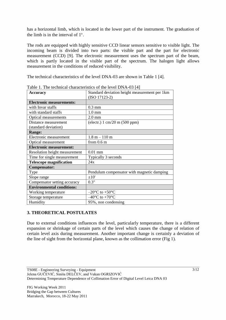
The technical characteristics of the level DNA-03 are shown in Table 1 [4].
Table 1. The technical characteristics of the level DNA-03 [4]
Accuracy Standard deviation height measurement per 1km
(ISO 17123-2)
Electronic measurements:
with Invar staffs 0.3 mm
with standard staffs 1.0 mm
Optical measurements 2.0 mm
Distance measurement
(standard deviation)
(electr.) 1 cm/20 m (500 ppm)
Range:
Electronic measurement 1.8 m – 110 m
Optical measurement from 0.6 m
Electronic measurement:
Resolution height measurement 0.01 mm
Time for single measurement Typically 3 seconds
Telescope magnification 24x
Compensator:
Type Pendulum compensator with magnetic damping
Slope range ±10'
Compensator setting accuracy 0.3"
Environmental conditions:
Working temperature –20°C to +50°C
Storage temperature –40°C to +70°C
Humidity 95%, non condensing
3. THEORETICAL POSTULATES
Due to external conditions influences the level, particularly temperature, there is a different
expansion or shrinkage of certain parts of the level which causes the change of relation of
certain level axis during measurement. Another important change is certainly a deviation of
the line of sight from the horizontal plane, known as the collimation error (Fig 1).
TS08E - Engineering Surveying - Equipment
Jelena GUĈEVIĆ, Siniša DELĈEV, and Vukan OGRIZOVIĆ
Determining Temperature Dependence of Collimation Error of Digital Level Leica DNA 03
FIG Working Week 2011
Bridging the Gap between Cultures
Marrakech, Morocco, 18-22 May 2011
4/12
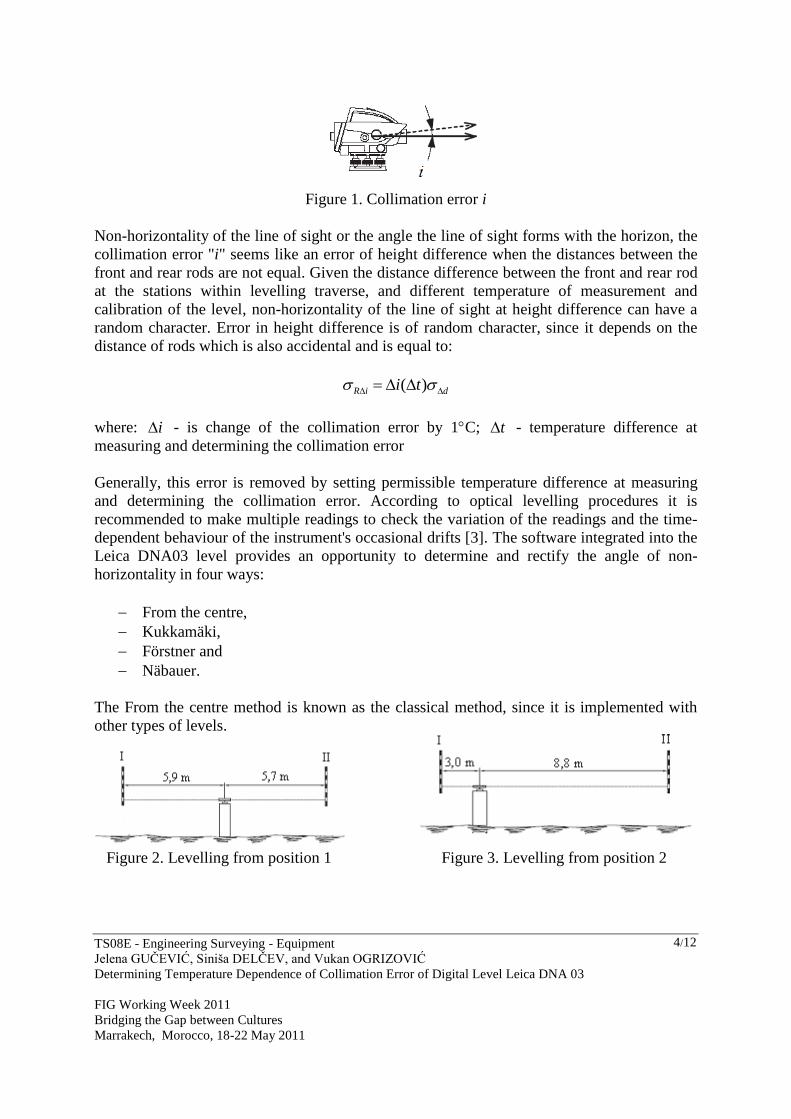
Figure 1. Collimation error i
Non-horizontality of the line of sight or the angle the line of sight forms with the horizon, the
collimation error "i" seems like an error of height difference when the distances between the
front and rear rods are not equal. Given the distance difference between the front and rear rod
at the stations within levelling traverse, and different temperature of measurement and
calibration of the level, non-horizontality of the line of sight at height difference can have a
random character. Error in height difference is of random character, since it depends on the
distance of rods which is also accidental and is equal to:
( ) R i di t
where: i - is change of the collimation error by 1C; t - temperature difference at
measuring and determining the collimation error
Generally, this error is removed by setting permissible temperature difference at measuring
and determining the collimation error. According to optical levelling procedures it is
recommended to make multiple readings to check the variation of the readings and the time-
dependent behaviour of the instrument's occasional drifts [3]. The software integrated into the
Leica DNA03 level provides an opportunity to determine and rectify the angle of non-
horizontality in four ways:
From the centre,
Kukkamäki,
Förstner and
Näbauer.
The From the centre method is known as the classical method, since it is implemented with
other types of levels.
Figure 2. Levelling from position 1 Figure 3. Levelling from position 2

TS08E - Engineering Surveying - Equipment
Jelena GUĈEVIĆ, Siniša DELĈEV, and Vukan OGRIZOVIĆ
Determining Temperature Dependence of Collimation Error of Digital Level Leica DNA 03
FIG Working Week 2011
Bridging the Gap between Cultures
Marrakech, Morocco, 18-22 May 2011
5/12
Determining the collimation error with the From the centre method consists of measuring the
height difference of the levelling side from the positions 1 and 2, respectively, within the
polygon of the Metrological Laboratory (ML160) according to the following procedure.
Levelling from the position 1 (Figure 2): From the central pillar of the laboratory on which
the instrument is set up, the reading is executed with fixed rods labelled I and II. The reading
is done in four series with the change of height of the level. The change of height of the level
is done by acting on the position screws. For each pair of readings the height difference is
calculated:
, 1, 4 j II I j
h l l j
(1)
where:
jh - height difference obtained by levelling from position 1,
III ll , - reading on the fixed rods,
j - series number.
Levelling from the position 2 (Figure 3): The level is set up on the pillar number 2 of the
laboratory and the reading begins on the fixed rods labelled I and II. The reading is done in
four series with the change of height of the level. The change of height of the level is done by
acting on the position screws. For each pair of readings the height difference is calculated:
4,1,''' jllh
jIIIj
(2)
with: ' jh - height difference obtained by levelling from position 2,
' ',I IIl l - reading on the fixed rods,
j - series number.
Upon the completed observation, we proceed to determine the angle i. The angle i is
determined in four series.
4,1,"
'
j
dd
hhi
zp
jj
j
(3)
with:
pd - distance to the closer rod (labelled II) when levelling from the position 1
zd - distance to the farther rod (labelled I) when levelling from the position 2.
TS08E - Engineering Surveying - Equipment
Jelena GUĈEVIĆ, Siniša DELĈEV, and Vukan OGRIZOVIĆ
Determining Temperature Dependence of Collimation Error of Digital Level Leica DNA 03
FIG Working Week 2011
Bridging the Gap between Cultures
Marrakech, Morocco, 18-22 May 2011
6/12
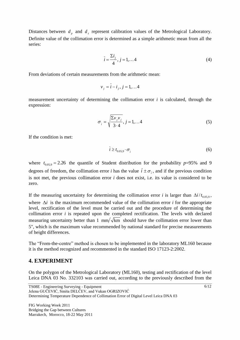
Distances between pd and zd represent calibration values of the Metrological Laboratory.
Definite value of the collimation error is determined as a simple arithmetic mean from all the
series:
, 1, 4
4
jii j
(4)
From deviations of certain measurements from the arithmetic mean:
4,1, jiiv jj
measurement uncertainty of determining the collimation error i is calculated, through the
expression:
4,1,
43
j
vv jj
i
(5)
If the condition is met:
i
ti 9,05.0
(6)
where 26.29,05.0 t the quantile of Student distribution for the probability p=95% and 9
degrees of freedom, the collimation error i has the value i
i , and if the previous condition
is not met, the previous collimation error i does not exist, i.e. its value is considered to be
zero.
If the measuring uncertainty for determining the collimation error i is larger than 9,05.0/ ti ,
where i is the maximum recommended value of the collimation error i for the appropriate
level, rectification of the level must be carried out and the procedure of determining the
collimation error i is repeated upon the completed rectification. The levels with declared
measuring uncertainty better than 1 mm km should have the collimation error lower than
5", which is the maximum value recommended by national standard for precise measurements
of height differences.
The “From-the-centre” method is chosen to be implemented in the laboratory ML160 because
it is the method recognized and recommented in the standard ISO 17123-2:2002.
4. EXPERIMENT
On the polygon of the Metrological Laboratory (ML160), testing and rectification of the level
Leica DNA 03 No. 332103 was carried out, according to the previously described from the
TS08E - Engineering Surveying - Equipment
Jelena GUĈEVIĆ, Siniša DELĈEV, and Vukan OGRIZOVIĆ
Determining Temperature Dependence of Collimation Error of Digital Level Leica DNA 03
FIG Working Week 2011
Bridging the Gap between Cultures
Marrakech, Morocco, 18-22 May 2011
7/12
centre method. After that, we determined the change of the collimation error i under the
influence of temperature changes, by cooling and heating the instrument. The instrument was
turned on before the procedure of cooling and heating, in order to avoid the temperature
changes caused by internal electronic circuits. The measuring equipment was as follows:
DNA-03 instrument and the corresponding invar rod No. 23829.
Instrument Leica DNA 03 is cooled in a chamber of the Institute of Materials and Structures
of the Faculty of Civil Engineering in Belgrade to the temperature of -10C. Due to
insufficient retention in the chamber, its operating temperature in the laboratory was 3C. The
instrument is placed on the reinforced concrete pillar 4, d=5.9 m away from the invar bar-
code rod. 10 measurements were carried out for each degree of temperature cooling in the
range of 3C to 25C.
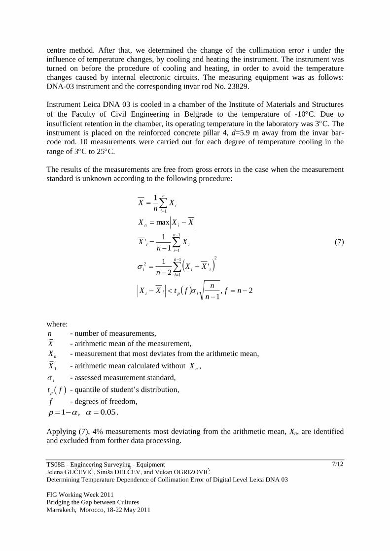
The results of the measurements are free from gross errors in the case when the measurement
standard is unknown according to the following procedure:
2,1
'2
1
1
1'
max
1
21
1
2
1
1
1
nfn
nftXX
XXn
Xn
X
XXX
Xn
X
ipii
n
i
iii
n
i
ii
in
n
i
i
(7)
where:
n - number of measurements,
X - arithmetic mean of the measurement,
nX - measurement that most deviates from the arithmetic mean, ´
1X - arithmetic mean calculated without nX ,
i - assessed measurement standard,
pt f - quantile of student’s distribution,
f - degrees of freedom,
1 , 0.05 p .
Applying (7), 4% measurements most deviating from the arithmetic mean, Xn, are identified
and excluded from forther data processing.
TS08E - Engineering Surveying - Equipment
Jelena GUĈEVIĆ, Siniša DELĈEV, and Vukan OGRIZOVIĆ
Determining Temperature Dependence of Collimation Error of Digital Level Leica DNA 03
FIG Working Week 2011
Bridging the Gap between Cultures
Marrakech, Morocco, 18-22 May 2011
8/12
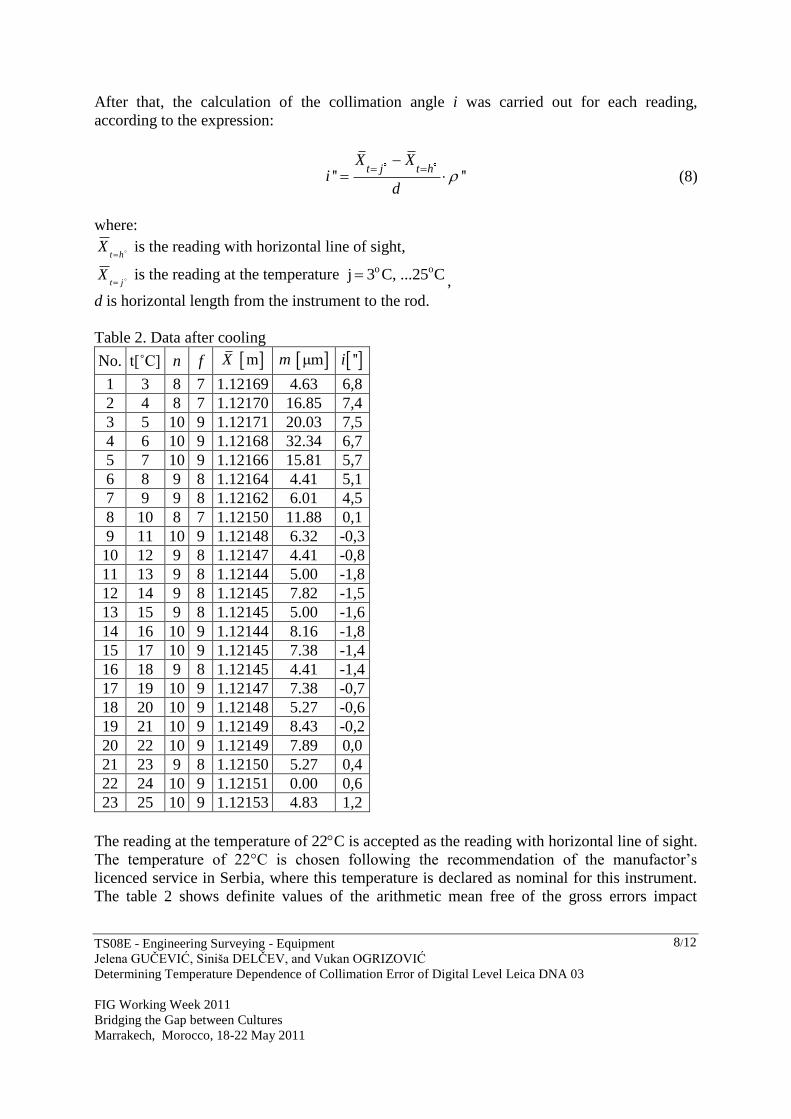
After that, the calculation of the collimation angle i was carried out for each reading,
according to the expression:
'' ''t j t h
X Xi
d
(8)
where:
htX
is the reading with horizontal line of sight,
jtX
is the reading at the temperature o oj 3 C, ...25 C ,
d is horizontal length from the instrument to the rod.
Table 2. Data after cooling
No. t[˚C] n f mX μmm ''i
1 3 8 7 1.12169 4.63 6,8
2 4 8 7 1.12170 16.85 7,4
3 5 10 9 1.12171 20.03 7,5
4 6 10 9 1.12168 32.34 6,7
5 7 10 9 1.12166 15.81 5,7
6 8 9 8 1.12164 4.41 5,1
7 9 9 8 1.12162 6.01 4,5
8 10 8 7 1.12150 11.88 0,1
9 11 10 9 1.12148 6.32 -0,3
10 12 9 8 1.12147 4.41 -0,8
11 13 9 8 1.12144 5.00 -1,8
12 14 9 8 1.12145 7.82 -1,5
13 15 9 8 1.12145 5.00 -1,6
14 16 10 9 1.12144 8.16 -1,8
15 17 10 9 1.12145 7.38 -1,4
16 18 9 8 1.12145 4.41 -1,4
17 19 10 9 1.12147 7.38 -0,7
18 20 10 9 1.12148 5.27 -0,6
19 21 10 9 1.12149 8.43 -0,2
20 22 10 9 1.12149 7.89 0,0
21 23 9 8 1.12150 5.27 0,4
22 24 10 9 1.12151 0.00 0,6
23 25 10 9 1.12153 4.83 1,2
The reading at the temperature of 22C is accepted as the reading with horizontal line of sight.
The temperature of 22°C is chosen following the recommendation of the manufactor’s
licenced service in Serbia, where this temperature is declared as nominal for this instrument.
The table 2 shows definite values of the arithmetic mean free of the gross errors impact
TS08E - Engineering Surveying - Equipment
Jelena GUĈEVIĆ, Siniša DELĈEV, and Vukan OGRIZOVIĆ
Determining Temperature Dependence of Collimation Error of Digital Level Leica DNA 03
FIG Working Week 2011
Bridging the Gap between Cultures
Marrakech, Morocco, 18-22 May 2011
9/12
mX , values of standard deviations μmm and values of the angle i at different
temperatures of instruments.
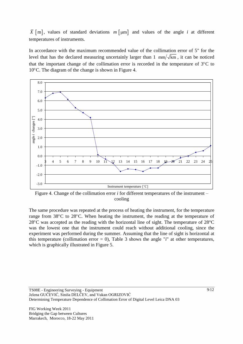
In accordance with the maximum recommended value of the collimation error of 5" for the
level that has the declared measuring uncertainly larger than 1 mm km , it can be noticed
that the important change of the collimation error is recorded in the temperature of 3C to
10C. The diagram of the change is shown in Figure 4.
-3.0
-2.0
-1.0
0.0
1.0
2.0
3.0
4.0
5.0
6.0
7.0
8.0
3 4 5 6 7 8 9 10 11 12 13 14 15 16 17 18 19 20 21 22 23 24 25
Instrument temperature [˚C]
angle
i c
han
ges
["]
Figure 4. Change of the collimation error i for different temperatures of the instrument –
cooling
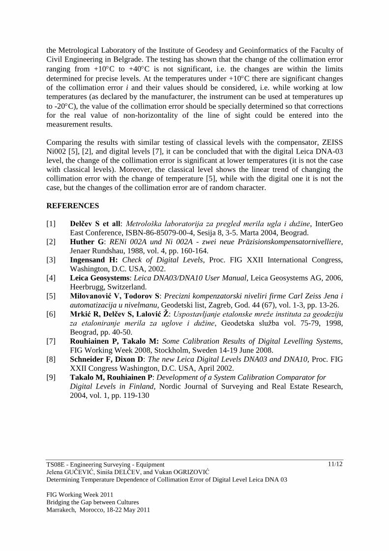
The same procedure was repeated at the process of heating the instrument, for the temperature
range from 38C to 28C. When heating the instrument, the reading at the temperature of
28C was accepted as the reading with the horizontal line of sight. The temperature of 28°C
was the lowest one that the instrument could reach without additional cooling, since the
experiment was performed during the summer. Assuming that the line of sight is horizontal at
this temperature (collimation error = 0), Table 3 shows the angle "i" at other temperatures,
which is graphically illustrated in Figure 5.

TS08E - Engineering Surveying - Equipment
Jelena GUĈEVIĆ, Siniša DELĈEV, and Vukan OGRIZOVIĆ
Determining Temperature Dependence of Collimation Error of Digital Level Leica DNA 03
FIG Working Week 2011
Bridging the Gap between Cultures
Marrakech, Morocco, 18-22 May 2011
10/12
Table 3. Data after heating
No. t[˚C] n f mX μmm ''i
1 38 10 9 1.12148 33.81 -2,4 2 37 10 9 1.12156 20.25 0,5 3 36 8 7 1.12158 4.63 1,2 4 35 9 8 1.12157 7.07 0,8 5 34 9 8 1.12156 9.28 0,4 6 33 10 9 1.12156 8.76 0,5 7 32 10 9 1.12157 14.30 0,6 8 31 9 8 1.12156 5.00 0,3 9 30 10 9 1.12155 7.89 0,1 10 29 10 9 1.12155 4.83 0,0 11 28 10 9 1.12155 20.44 0,0
-3
-2
-2
-1
-1
0
1
1
2
38 37 36 35 34 33 32 31 30 29 28
Instrument temperature [˚C]
an
gle
i c
han
ges
["]
Figure 5. Change of the collimation error i for different temperatures of the instrument –
heating
As the maximum recommended value of the collimation error is 5", it can be noticed that in
the process of heating the instrument, for the temperature range from 38C to 28C there are
no significant changes up to temperature of 37C.
5. CONCLUSION
Leica DNA 03 level is the instrument of modern design that largely facilitates the work of
geodetic professionals due to its software and possibilities.
The testing of the effects of temperature changes of the instrument on the position of the line
of sight at the digital level with the compensator during cooling and heating was carried out in
TS08E - Engineering Surveying - Equipment
Jelena GUĈEVIĆ, Siniša DELĈEV, and Vukan OGRIZOVIĆ
Determining Temperature Dependence of Collimation Error of Digital Level Leica DNA 03
FIG Working Week 2011
Bridging the Gap between Cultures
Marrakech, Morocco, 18-22 May 2011
11/12
the Metrological Laboratory of the Institute of Geodesy and Geoinformatics of the Faculty of
Civil Engineering in Belgrade. The testing has shown that the change of the collimation error
ranging from +10C to +40C is not significant, i.e. the changes are within the limits
determined for precise levels. At the temperatures under +10C there are significant changes
of the collimation error i and their values should be considered, i.e. while working at low
temperatures (as declared by the manufacturer, the instrument can be used at temperatures up
to -20C), the value of the collimation error should be specially determined so that corrections
for the real value of non-horizontality of the line of sight could be entered into the
measurement results.
Comparing the results with similar testing of classical levels with the compensator, ZEISS
Ni002 [5], [2], and digital levels [7], it can be concluded that with the digital Leica DNA-03
level, the change of the collimation error is significant at lower temperatures (it is not the case
with classical levels). Moreover, the classical level shows the linear trend of changing the
collimation error with the change of temperature [5], while with the digital one it is not the
case, but the changes of the collimation error are of random character.
REFERENCES
[1] Delčev S et all: Metrološka laboratorija za pregled merila ugla i dužine, InterGeo
East Conference, ISBN-86-85079-00-4, Sesija 8, 3-5. Marta 2004, Beograd.
[2] Huther G: RENi 002A und Ni 002A - zwei neue Präzisionskompensatornivelliere,
Jenaer Rundshau, 1988, vol. 4, pp. 160-164.
[3] Ingensand H: Check of Digital Levels, Proc. FIG XXII International Congress,
Washington, D.C. USA, 2002.
[4] Leica Geosystems: Leica DNA03/DNA10 User Manual, Leica Geosystems AG, 2006,
Heerbrugg, Switzerland.
[5] Milovanović V, Todorov S: Precizni kompenzatorski niveliri firme Carl Zeiss Jena i
automatizacija u nivelmanu, Geodetski list, Zagreb, God. 44 (67), vol. 1-3, pp. 13-26.
[6] Mrkić R, Delčev S, Lalović Ž: Uspostavljanje etalonske mreže instituta za geodeziju
za etaloniranje merila za uglove i dužine, Geodetska služba vol. 75-79, 1998,
Beograd, pp. 40-50.
[7] Rouhiainen P, Takalo M: Some Calibration Results of Digital Levelling Systems,
FIG Working Week 2008, Stockholm, Sweden 14-19 June 2008.
[8] Schneider F, Dixon D: The new Leica Digital Levels DNA03 and DNA10, Proc. FIG
XXII Congress Washington, D.C. USA, April 2002.
[9] Takalo M, Rouhiainen P: Development of a System Calibration Comparator for
Digital Levels in Finland, Nordic Journal of Surveying and Real Estate Research,
2004, vol. 1, pp. 119-130
TS08E - Engineering Surveying - Equipment
Jelena GUĈEVIĆ, Siniša DELĈEV, and Vukan OGRIZOVIĆ
Determining Temperature Dependence of Collimation Error of Digital Level Leica DNA 03
FIG Working Week 2011
Bridging the Gap between Cultures
Marrakech, Morocco, 18-22 May 2011
12/12
BIOGRAPHICAL NOTES
Prof. Dr. Siniša Delčev, born in 1959. Graduated in 1982 as Dipl.-Ing. in Geodesy and
obtaining doctorate degree in 2001, both from Belgrade University, until 1983 teaching
assistant at Belgrade University. Since 2002 Assistant Professor of Geodetic Metrology and
Higher Geodesy
Prof. Dr. Jelena Gučević, born in 1970. Graduated in 1994 as Dipl.-Ing. in Geodesy and
obtaining doctorate degree in 2005, both from Belgrade University, until 1995 teaching
assistant at Belgrade University. Since 2002 Assistant Professor of Surveying.
Prof. Dr. Vukan Ogrizović, born in 1970. Graduated in 1996 as Dipl.-Ing. in Geodesy and
obtaining doctorate degree in 2007, both from Belgrade University, until 1997 teaching
assistant at Belgrade University. Since 2008 Assistant Professor of Geodetic Astronomy.
CONTACTS:
Assistant Professor Siniša Delĉev, Ph.D.
University of Belgrade
Faculty of Civil Engineering
Department of Geodesy and Geoinformatics
Bulevar kralja Aleksandra 73
Belgrade
SERBIA
Tel. + 381 11 3370293
Fax + 381 11 3370293
Email: [email protected]
Web site: www.grf.bg.ac.rs
Assistant Professor Jelena Guĉević, Ph.D.
University of Belgrade
Faculty of Civil Engineering
Department of Geodesy and Geoinformatics
Bulevar kralja Aleksandra 73
Belgrade
SERBIA
Tel. + 381 11 3370293
Fax + 381 11 3370293
Email: [email protected]
Web site: www.grf.bg.ac.rs
Assistant Professor Vukan Ogrizović, Ph.D.
University of Belgrade
Faculty of Civil Engineering
Department of Geodesy and Geoinformatics
Bulevar kralja Aleksandra 73
Belgrade
SERBIA
Tel. + 381 11 3370293
Fax + 381 11 3370293
Email: [email protected]
Web site: www.grf.bg.ac.rs