determination of elements and carbon content of … · determination of elements and carbon content...
TRANSCRIPT
1547
ACTA UNIVERSITATIS AGRICULTURAE ET SILVICULTURAE MENDELIANAE BRUNENSIS
Volume 64 171 Number 5, 2016
http://dx.doi.org/10.11118/actaun201664051547
DETERMINATION OF ELEMENTS AND CARBON CONTENT OF STAINLESS
STEEL WELDED PIPELINE
Pavel Hudeček1. Petr Dostál1
1 Department of Technology and Automobile Transport. Mendel University in Brno. Zemědělská 1. 613 00 Brno. Czech Republic
Abstract
HUDEČEK PAVEL. DOSTÁL PETR. 2016. Determination of Elements and Carbon Content of Stainless Steel Welded Pipeline. Acta Universitatis Agriculturae et Silviculturae Mendelianae Brunensis. 64(5): 1547–1554.
Find out defects or problems of welds are not so simple from time to time. Specially. If weld has been made in rough environmental conditions like high temperature. dusty wind and humidity. It is important to assure have good conditions to realize basic step of welding. For welding. have been used welding procedures specification and procedure qualification record. However. difficult conditions. documentations rightness or human errors are always here. Common weld defects like cracks. porosity. lack of penetration and distortion can compromise the strength of the base metal. as well as the integrity of the weld. According of site inspection. there were suspicion of inclusions. leaker or segregation in root of weld. Surface treatment after welding and keep the intervals between single welds to not overheat the pipes. To recognize those suspicions. mechanical testing around weld joint. determination of carbon content and inductively coupled plasma atomic emission spectroscopy will be done.
Keywords: icp‑oes method, hardness test, determination of carbon content, microstructure, macrostructure, weld joint, affected zone
INTRODUCTIONHardness tests on welds are performed to evaluate
the hardness distribution across the weld joint. including the base material. heat affected zone(s) and weld metal. When welding two materials together. heat is applied to the materials at the joints. which may alter the microstructure of the material adjacent to the weld. To check whether the material properties (microstructure) has been altered by the welding. hardness distribution measurements are made across the weld joint from the base material(s) through the heat affected zone (HAZ). fusion line and weld metal. to the same areas at the other side of the joint. If the hardness values turn out to be. too high it could indicate unwanted alteration of the microstructure making the weld
too brittle and thus unsuitable for the application (Struers. 2012).
Hardness distribution measurements of welds are commonly measured with HV5 or HV10. The exact positioning of the test points depend on the type of weld joint. detailed in various norms and standards.
Codes and standards created by the American Welding Society specify exactly how a joint must look when the job is accomplished. Depending on the usage. societies may have a say in the project for example American Society of Mechanical Engineers (ASME). the American Petroleum Institute (API). and the American Society for Nondestructive Testing (ASNT).

1548 Pavel Hudeček, Petr Dostál
Code standards for welding the finished shape. sizes and extent of any anomalies in the end weld. A one crack is considered as a defect. automatically failing an inspection. The following problems should accrued:• human irresponsibility or errors• bad welding condition or preparation• poor joint design or fit‑up• incorrect settings or a machine deficiency• wrong shielding gas or flow rate• inadequate pre or post‑heat treatment• using the wrong (or a defective) rod /wire• a hot or cold ambient temperature. high humidity.
or other atmospheric condition
Determination of elements by ICP-OES method
ICP. abbreviation for Inductively Coupled Plasma. is one method of optical emission spectrometry. When plasma energy is given to an analysis sample from outside. the component elements (atoms) is excited. When the excited atoms return to low energy position. emission rays (spectrum rays) are released and the emission rays that correspond to the photon wavelength are measured. The element type is determined based on the position of the photon rays. and the content of each element is determined based on the rays’ intensity (RoHS. 2014).
MATERIALS AND METHODSThe goal of testing in this article was to compare
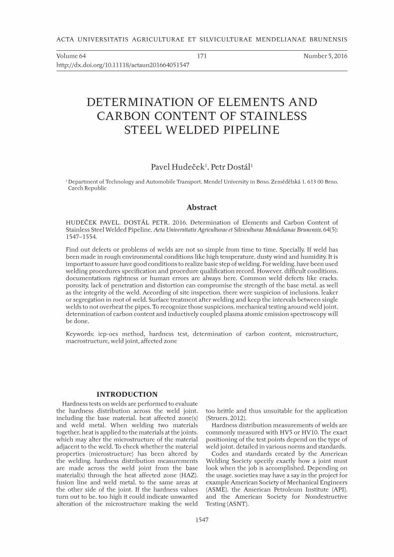
samples see Figure 3. Figure 4 and Figure 5. Samples
were tested by laboratory to discover inadequacies. The pipeline used to for firefighting in Iraq’s refinery. The water contains chloride according of water analysis.• Hardness test• Room temperature tension test• Determination of elements by ICP‑OES method• Determination of carbon content by IR absorption
after combustionTubes 88.9 × 3.05 and 88.9 × 3.05Material ASTM A 312 – TP316Land ASTM A 312 – TP316LWelding method 141 + 111
The experimentalFor the identification of the joint and tube external
surface defects in zones cross cuts were made in these zones indicated as sample 3–J3. sample 3–J5. sample 3 elbow as show Figures 6. 7 and 8. Samples are for macrostructure assessment and the samples of tubes were given for analysis. On the weld joint and vicinity were found deficiencies of surface. black spots (see Figure 6. 7 and 8) and plugged surface near weld joint.
Hardness testThe relative measurement uncertainty. which
was calculated by reference of coefficient K = 2 corresponding to the reliability ca approximately 95 % is 3.5 %. The uncertainty was calculated from the measurement statistic.
I: Samples of hardness test
Hardness test Hardness scale Designation
J5 HBW5–750
HV 10
J3 HBW5–750
HV 10
Elbow HBW5–750
HV 10

Determination of Elements and Carbon Content of Stainless Steel Welded Pipeline 1549
1: Hardness distribution measurements of weld (Struers. 2012)
2: ICP-OES (RoHS. 2014)
1550 Pavel Hudeček, Petr Dostál
3: Tube sample J3
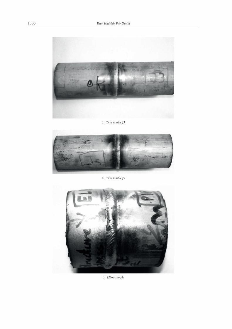
4: Tube sample J5
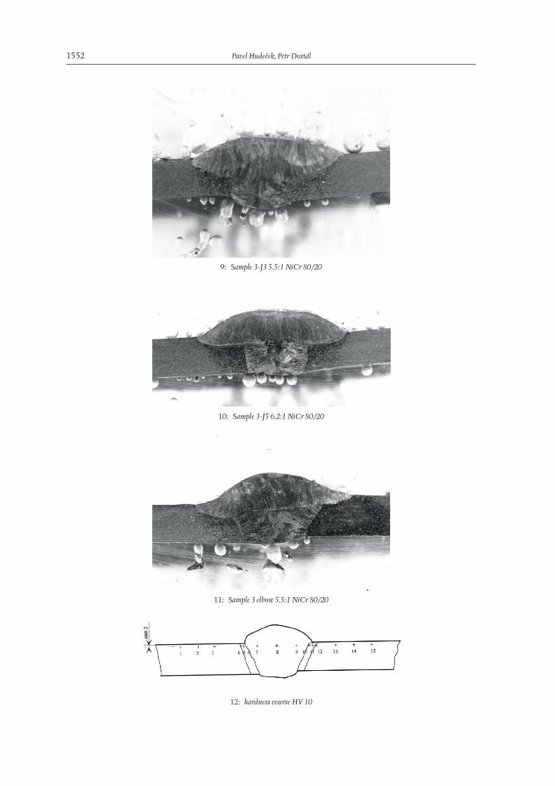
5: Elbow sample

Determination of Elements and Carbon Content of Stainless Steel Welded Pipeline 1551
6: Tube sample 3-J3
7: Tube sample 3-J5
8: Tube sample 3 elbow
1552 Pavel Hudeček, Petr Dostál
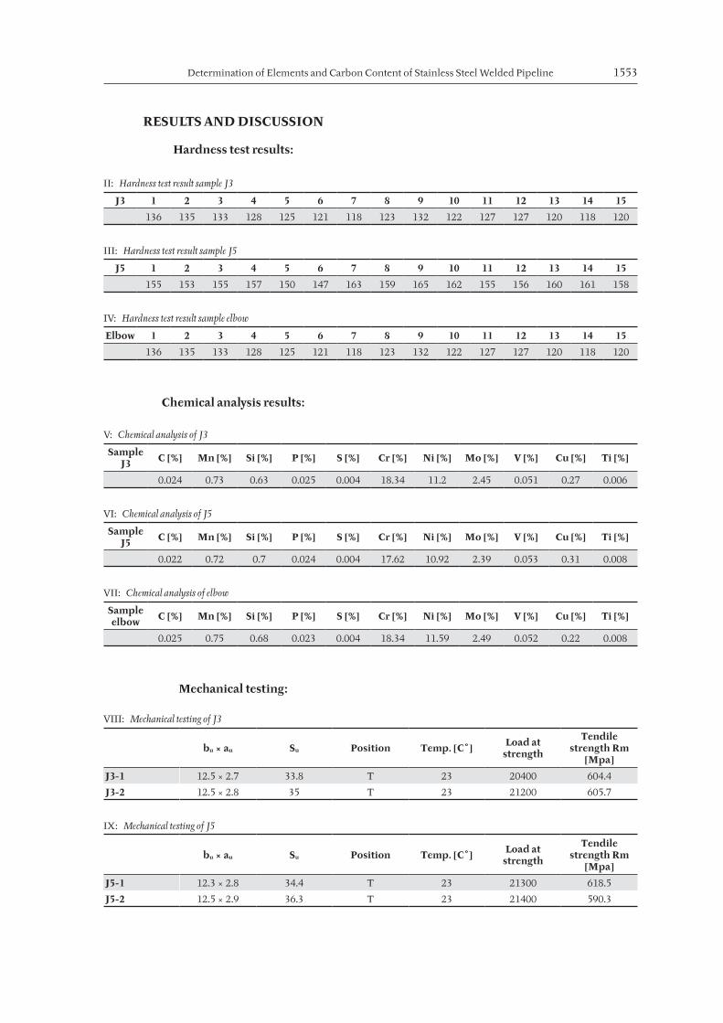
9: Sample 3-J3 5.5:1 NiCr 80/20
10: Sample 3-J5 6.2:1 NiCr 80/20
11: Sample 3 elbow 5.5:1 NiCr 80/20
12: hardness course HV 10
Determination of Elements and Carbon Content of Stainless Steel Welded Pipeline 1553
RESULTS AND DISCUSSION
Hardness test results:
Chemical analysis results:
Mechanical testing:
II: Hardness test result sample J3
J3 1 2 3 4 5 6 7 8 9 10 11 12 13 14 15
136 135 133 128 125 121 118 123 132 122 127 127 120 118 120
III: Hardness test result sample J5
J5 1 2 3 4 5 6 7 8 9 10 11 12 13 14 15
155 153 155 157 150 147 163 159 165 162 155 156 160 161 158
IV: Hardness test result sample elbow
Elbow 1 2 3 4 5 6 7 8 9 10 11 12 13 14 15
136 135 133 128 125 121 118 123 132 122 127 127 120 118 120
V: Chemical analysis of J3
Sample J3 C [%] Mn [%] Si [%] P [%] S [%] Cr [%] Ni [%] Mo [%] V [%] Cu [%] Ti [%]
0.024 0.73 0.63 0.025 0.004 18.34 11.2 2.45 0.051 0.27 0.006
VI: Chemical analysis of J5
Sample J5 C [%] Mn [%] Si [%] P [%] S [%] Cr [%] Ni [%] Mo [%] V [%] Cu [%] Ti [%]
0.022 0.72 0.7 0.024 0.004 17.62 10.92 2.39 0.053 0.31 0.008
VII: Chemical analysis of elbow
Sample elbow C [%] Mn [%] Si [%] P [%] S [%] Cr [%] Ni [%] Mo [%] V [%] Cu [%] Ti [%]
0.025 0.75 0.68 0.023 0.004 18.34 11.59 2.49 0.052 0.22 0.008
VIII: Mechanical testing of J3
bu × au Su Position Temp. [C˚] Load at strength
Tendile strength Rm
[Mpa]
J3-1 12.5 × 2.7 33.8 T 23 20400 604.4
J3-2 12.5 × 2.8 35 T 23 21200 605.7
IX: Mechanical testing of J5
bu × au Su Position Temp. [C˚] Load at strength
Tendile strength Rm
[Mpa]
J5-1 12.3 × 2.8 34.4 T 23 21300 618.5
J5-2 12.5 × 2.9 36.3 T 23 21400 590.3
1554 Pavel Hudeček, Petr Dostál
CONCLUSIONAll of the tested samples were tested by Hardness test room temperature tension test. determination of elements by ICP‑OES method. determination of carbon content by IR absorption after combustion. There are the joints macrostructure from the zone in as can see on the Figure 6 and 7 for sample 3‑J3 and 3‑J5. As was mentioned. due to site inspection. suspicion of inclusions. leaker or segregation in root of weld surface treatment after welding and keep the intervals between single welds to not overheat the pipes were required. Samples were tested and investigated. According of mechanical testing and chemical analyzing the macrostructures are flawless.
Acknowledgements
The research has been supported by the project TP 4/2014: Analysis of degradation processes of modern materials used in agricultural technology; financed by IGA AF MENDELU.
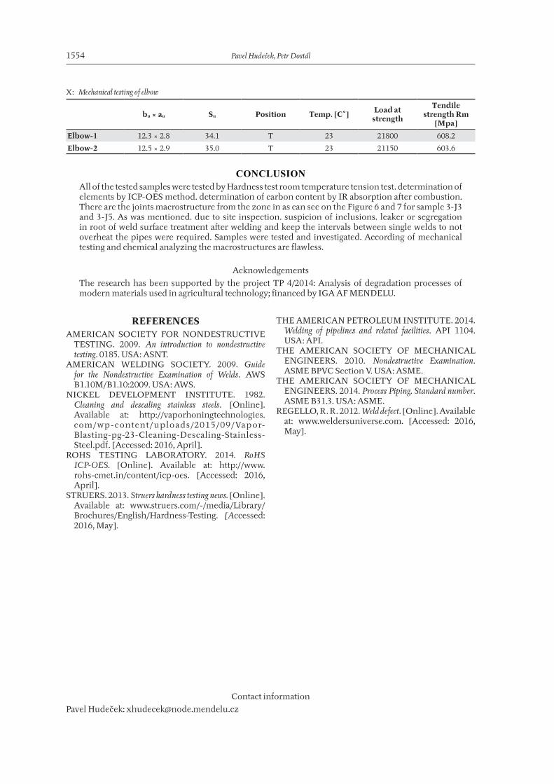
X: Mechanical testing of elbow
bu × au Su Position Temp. [C˚] Load at strength
Tendile strength Rm
[Mpa]
Elbow-1 12.3 × 2.8 34.1 T 23 21800 608.2
Elbow-2 12.5 × 2.9 35.0 T 23 21150 603.6
REFERENCESAMERICAN SOCIETY FOR NONDE STRUCTIVE
TESTING. 2009. An introduction to nondestructive testing. 0185. USA: ASNT.
AMERICAN WELDING SOCIETY. 2009. Guide for the Nondestructive Examination of Welds. AWS B1.10M/B1.10:2009. USA: AWS.
NICKEL DEVELOPMENT INSTITUTE. 1982. Cleaning and descaling stainless steels. [Online]. Available at: http://vaporhoningtechnologies.com/wp‑content/uploads/2015/09/Vap or‑Blasting‑pg‑23‑Cleaning‑Descaling‑Stainless‑Steel.pdf. [Accessed: 2016, April].
ROHS TESTING LABORATORY. 2014. RoHS ICP-OES. [Online]. Available at: http://www.rohs‑cmet.in/content/icp‑oes. [Accessed: 2016, April].
STRUERS. 2013. Struers hardness testing news. [Online]. Available at: www.struers.com/‑/media/Library/Brochures/English/Hardness‑Testing. [Accessed: 2016, May].
THE AMERICAN PETROLEUM INSTITUTE. 2014. Welding of pipelines and related facilities. API 1104. USA: API.
THE AMERICAN SOCIETY OF MECHANICAL ENGINEERS. 2010. Nondestructive Examination. ASME BPVC Section V. USA: ASME.
THE AMERICAN SOCIETY OF MECHANICAL ENGINEERS. 2014. Process Piping. Standard number. ASME B31.3. USA: ASME.
REGELLO, R. R. 2012. Weld defect. [Online]. Available at: www.weldersuniverse.com. [Accessed: 2016, May].
Contact information
Pavel Hudeček: [email protected]