determination of an unmanned mobile object orientation …ceur-ws.org/vol-1710/paper10.pdf ·...
TRANSCRIPT
Determination of an Unmanned Mobile Object Orientation by Natural Landmarks
Anton M. Korsakov, Ivan S. Fomin, Dmitry A. Gromoshinsky, Alexandr V. Bakhshiev, Dmitrii N. Stepanov, EkaterinaY. Smirnova 1
1 Russian State Scientific Center for Robotics and Technical Cybernetics (RTC), Saint-Petersburg, Russia
E-mail: [email protected]
Abstract. The paper is dedicated to determination of equipped with a video camera unmanned mobile object (e.g., a mobile robot) orientation by natural landmarks. The problem is relevant for solving the problem of autonomous movement of the mobile object at a given point of navigating using natural landmarks linked to the map location. The algorithm for determining the orien-tation of an unmanned mobile object by natural landmarks in view of system conditioning at the point of calculation is proposed. The results of physical ex-periments of determining the orientation of an unmanned mobile object by natu-ral landmarks in dynamics are presented.
Keywords: Computer vision, mobile robots, objects orientation calculation
1 Introduction
The paper is dedicated to determination of an equipped with a video camera unmanned mobile object (eg, a mobile robot) orientation by natural landmarks. The problem is relevant for solving the problem of autonomous movement of the mobile object at a given point of navi-gating using natural landmarks linked to the map location. As natural landmarks we can use any objects on the scene, which the classifier was pre-trained and which have a binding to map of the scene. The minimum number of natural landmarks required to solve the problem is three. A modified cascade Viola-Jones detector was used as a classifier. As the map of the scene it can be used any scene image (such as a satel-lite image service "Yandex-map") with marked natural landmarks by which orientation is performed. To determine the orientation the scene metric characteristics are not required. It is understood that the camera calibration procedure has passed, ie, we know the direction to the natu-
ral landmarks relative to the central optical axis of the camera. This solves the flat task, ie coordinates of landmarks are taken in projection on a plane of motion. The result of work is the misalignment angle be-tween real mobile object direction and calculated one.
2 A mathematical model for determining of an unmanned mobile object orientation by natural landmarks
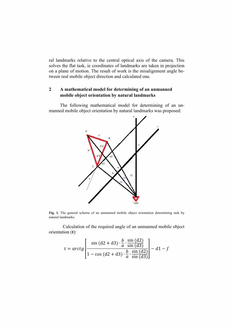
The following mathematical model for determining of an un-manned mobile object orientation by natural landmarks was proposed:
Fig. 1. The general scheme of an unmanned mobile object orientation determining task by natural landmarks.
Calculation of the required angle of an unmanned mobile object orientation (t):
𝑡 = 𝑎𝑟𝑐𝑡𝑔sin (d2+ d3) ∙ 𝑏𝑎 ∙
sin (d2)sin (d3)
1− cos (d2+ d3) ∙ 𝑏𝑎 ∙sin (d2)sin (d3)
− 𝑑1− 𝑓
3 Error investigations of an unmanned mobile object orientation determining by natural landmarks on computer and physical models
To check the proposed mathematical model adequacy the console application on C++ implemented allowing both to calculate the angle of an unmanned mobile object orientation in any system configuration and to perform the full run of all the possible natural landmarks positions on the coordinate plane relative to an unmanned object adjusted posi-tion and orientation with the orientation angle calculation for each con-figuration and comparison of the obtained result with the adjusted one.
In computer model investigation the following criteria of the mathematical model equations resolving were mounted:
1) Coordinates of natural landmarks should not coincide; 2) Directions to natural landmarks should not coincide; 3) Directions to natural landmarks should not coincide with the ax-
is of motion of an unmanned mobile object; 4) Directions and angles ratio that determine their relative position
should meet the criterion: a) 𝜸 ≠ 𝛏− 𝜷, in case
𝒅𝟏 + 𝒅𝟐 ≥ 𝝅 𝒂𝒏𝒅 △ 𝑨𝑩𝑪 𝒊𝒔 𝒄𝒍𝒐𝒄𝒌𝒘𝒊𝒔𝒆 b) 𝜸 ≠ −𝛏− 𝜷, in case
𝒅𝟏 + 𝒅𝟐 < 𝝅 𝒂𝒏𝒅 △ 𝑨𝑩𝑪 𝒊𝒔 𝒄𝒐𝒖𝒏𝒕𝒆𝒓𝒄𝒍𝒐𝒄𝒌𝒘𝒊𝒔𝒆
Failure of criterion 4 can lead to unresolved equation. The study
of the computer model showed 2.43% of natural landmarks configura-tions that do not meet the criterion 4.
The investigation of the error arising from the natural landmarks recognition mistakes was performed on the obtained computer model. The unmanned mobile object orientation measurement error was calcu-lated by variation of the input system parameters (directions on the nat-ural landmarks).
The results of an unmanned mobile object orientation error cal-culation are shown on fig. 2. Varying of directions to natural landmarks was carried out independently for each of the natural landmarks.

a)
b)
Fig. 2. The dependence between the unmanned mobile object orientation measurement errors (degrees) and the error in natural landmarks finding (pixels).
On fig. 2 variation of natural landmarks coordinates determining errors was performed within [-8,8] pixels. Fig. 2(a) shows the variants of natural landmarks configuration satisfying the criterion 4 in case of mobile object passage side or through the landmarks. Fig. 2(b) showss the variant, when the triangle formed by the natural landmarks is close to the degenerate.
Aside from investigations on the computer model the physical experiment was performed. A theodolite was used to determine the di-rection on the natural landmarks (replacing the calibrated camera). The distances and the angles between the landmarks were measured on the satellite image obtained with “Yandex Map” service. Centimeters were selected as a unit of measurement of the distance between the land-marks.
Fig. 3 represents six theodolite positions relative to the natural landmarks and the calculated value of the theodolite deviation from the zero point to each the position. The direction of the theodolite motion was selected in parallel with the model required trajectory (zero point),
1 2 3 4 5 6 7 8Fig3(a) 0,751,512,283,073,864,665,486,30
Fig3(c) 0,911,832,763,714,665,636,617,59
Fig3(f) 0,741,391,972,462,873,203,433,57
0,002,004,006,008,00
maxim
umerror
(dgr)
1 2 3Fig3(d) 14,20 39,10 98,46
0,00
50,00
100,00
150,00
maxim
um
error(dgr)
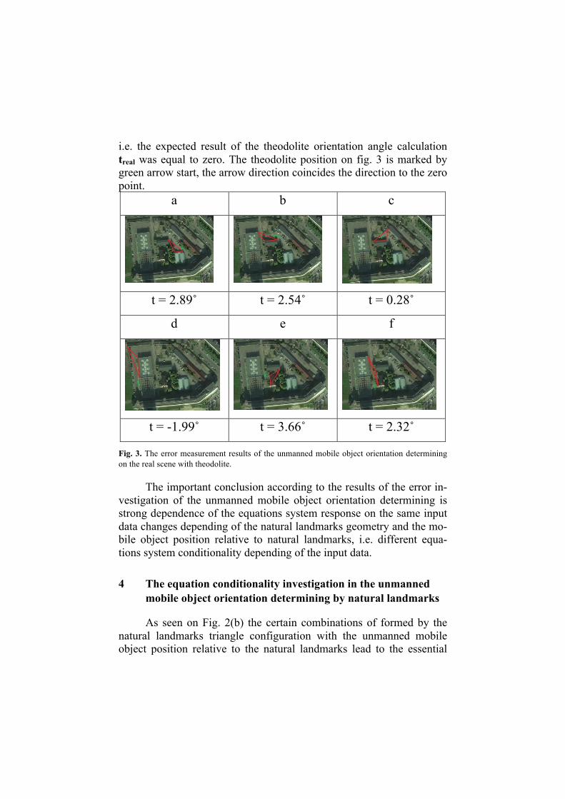
i.e. the expected result of the theodolite orientation angle calculation treal was equal to zero. The theodolite position on fig. 3 is marked by green arrow start, the arrow direction coincides the direction to the zero point.
a b c
t = 2.89˚ t = 2.54˚ t = 0.28˚
d e f
t = -1.99˚ t = 3.66˚ t = 2.32˚
Fig. 3. The error measurement results of the unmanned mobile object orientation determining on the real scene with theodolite.
The important conclusion according to the results of the error in-vestigation of the unmanned mobile object orientation determining is strong dependence of the equations system response on the same input data changes depending of the natural landmarks geometry and the mo-bile object position relative to natural landmarks, i.e. different equa-tions system conditionality depending of the input data.
4 The equation conditionality investigation in the unmanned mobile object orientation determining by natural landmarks
As seen on Fig. 2(b) the certain combinations of formed by the natural landmarks triangle configuration with the unmanned mobile object position relative to the natural landmarks lead to the essential

mobile object orientation determining error at small input parameters changes, i.e. to poor equation conditioning.
To study the conditioning of unmanned mobile object orientation determining equation the special application was developed.
The application allows to set any configuration of three natural landmarks, to set the adjusted error to input data, and to determine the zone of interest with any degree of detail. In addition, the program al-lows navigation in an area of natural landmarks through the image shift and zoom. The application allows checking error in any scene point.
Fig. 4 shows an example of the equation conditioning mapping result of the unmanned mobile object orientation determining by natu-ral landmarks forming the isosceles right triangle.
Fig. 4 The example of the equation conditioning mapping result of the unmanned mobile object orientation determining by natural landmarks forming isosceles right triangle.
On fig. 4 the natural landmarks are marked by red points. Yel-low grid can be switched by user to simplify the perception of distances on the map and have an arbitrary step. The image on fig. 4 is corre-sponding to example with adjusted error equal to one pixel. Green areas on the image are corresponding to scene points with error in orientation determining less than 0.1˚. Blue areas on the image are corresponding to scene points with error in orientation determining more than 10˚. The points with error between 0.1˚ and 10˚ are marked grayscale. White color corresponds to 0.1˚, black is corresponds to 10˚. Red areas on the image are corresponding to unresolved cases.
Fig. 5 shows dependence of mobile object orientation calcula-tion error in case when input error increases.

(a) (b)
(c) Fig. 5. The equation conditioning maps of the unmanned mobile object orientation determining with input error in (a) 1 pixel; (b) 3 pixels; (c) 5 pixels.
Green areas on the image are corresponding to scene points with error in orientation determining less than 0.5˚. Blue areas on the image are corresponding to scene points with error in orientation determining more than 10˚.
Fig. 6 shows the configuration of natural landmarks forming a triangle close to degenerate.
Fig. 6. The equation conditioning map of the unmanned mobile object orientation determining with the configuration of natural landmarks forming a triangle close to degenerate.
5 The physical experiment of the unmanned mobile object orientation determining by natural landmarks in the dynamics
The results of these studies were used in calculation of the un-manned mobile object orientation determining by natural landmarks in the mobile object test passages. The points with value of equation con-ditioning below the predetermined threshold were thrown out, which has greatly improved the final result.
The experiment included: 1) Classifier training by selected landmarks; 2) Marks arrangement on the scene and the calculation of their
coordinates in the selected coordinate system; 3) The selection of the mobile object route (straight line, 90
degrees turn) and painting it on the physical surface; 4) Mobile object transfer on the planned route with simultane-
ous recording by video camera mounted on a mobile object, and directed straight to the course of its movement. The scooter was used as the mobile object.
5) The calculation of the resulting video sequence in a special-ly designed program that included:
a. Recognition of natural landmarks; b. Landmarks splitting to triples; c. Calculation of mobile object orientation for each tri-
ple; d. Checking equation conditioning for each triple at a
given point; e. Filtering triangles with poor conditioning; f. Filtering triangles by the geometrical reasons (al-
ready passed the point, broken geometry of points location, the point is detected clearly above / below expected position, etc.).
6) Displaying the results in easy-to-study format. The result of this approach to the problem is the absence of
manifest errors in the determining of the unmanned mobile object ori-entation. The maximum error in the determining of the mobile object orientation is in range of 5 degrees. The average error in the determin-ing of an unmanned mobile object orientation is about 1 degree. An example of the test program is shown on Fig. 7.

(a) (b) Fig. 7. (a) The view of the window with the landmarks plan. (b) The input video sequence with landmarks tracking marked by color points.
On fig. 7 (a) colored points denote natural landmarks. Green tri-angle marks the natural landmarks by which the calculation is made. The maroon point shows the mobile object position and the white seg-ment shows the direction of its movement. Fig. 7 (b) shows a corre-sponding frame from a video camera mounted on a mobile object with recognized landmarks.
6 Conclusion
The efficiency of the algorithm as a whole is provided by: 1) topological (not methodological) approach to the formation
of the map, using only the relative coordinates; 2) A good detection; 3) To monitor the landmarks for several tens of frames (detec-
tion plus tracking); 4) Rejection due to bad decisions (instead the Jacobian is used
more "natural" criterion); 5) The individual steps are based on the known approaches, the
novelty is their aggregation. The following results were reached during researching: 1) The mathematical model for determining the orientation of
an unmanned mobile object by natural landmarks is de-scribed;
2) The results of the study of suggested mathematical model in determining the orientation of a computer model of an un-manned mobile object by natural landmarks are presented;
3) The results of the study of the error in determining the orien-tation of an unmanned mobile object by natural landmarks are presented;
4) The results of physical experiments of determining the ori-entation of an unmanned mobile object by natural landmarks in statics are presented;
5) The results of the equation conditioning study of the un-manned mobile object orientation determining by natural landmarks are presented;
6) The algorithm for determining the orientation of an un-manned mobile object by natural landmarks in view of sys-tem conditioning at the point of calculation is proposed.
7) The results of physical experiments of determining the ori-entation of the unmanned mobile object by natural land-marks in dynamics are presented.
Acknowledgements
This article was prepared with the financial support of the Ministry of Education, Agreement no. 14.578.21.0047 RFMEFI57814X0047 Agreement 2014-2020 Priority Technological Research and Develop-ment in the Russian Federation federal target program.
7 References
1. Nariniani A.S., Telerman V.V., Ushakov D.M., Shvetsov I.E. The Programming in limitations and underdetermined model // Infor-mation Technology №7, 1998. М., Publishing house “ Mechanical en-gineering ”. -P. 13-22.
2. Karpov V.E. Some features of the application underdetermined models in robotics, Collection of scientific papers.V.1. М.: PhisMath-Lit, 2009, p. 520-532.
3. Dmitrii Stepanov, Alexander Bakhshiev, Dmitrii Gro-moshinskii, Nikolai Kirpan and Philip Gundelakh. Determination of the Relative Position of Space Vehicles by Detection and Tracking of Nat-
ural Visual Features with the Existing TV-cameras. Ed. by M.Yu. Kha-chay, N. Konstantinova, A. Panchenko, D.I. Ignatov, G.V. Labunets: Analysis of Images, Social Networks and Texts. Fourth International Conference, AIST 2015, Yekaterinburg, Russia, April 9-11, 2015, Re-vised Selected Papers. Communications in Computer and Information Science, Vol. 542, pp. 431–442, Springer.
4. A.V. Bakhshiev, A.M. Korsakov. Application of a TLD meth-od to a problem of objects tracking in a task of space docking by TV picture // Extreme Robotics – robotics for work in hazardous environ-ments. // Proceedings of the 7th International Symposium. St.-Petersburg: publishing house “Politechniqual service”, 2013. – P. 293-297.