determination of aircraft orientation for a vision-based system using artificial neural networks
TRANSCRIPT

P1: VBI
Journal of Mathematical Imaging and Vision KL550-04-Agarwal January 29, 1998 12:17
Journal of Mathematical Imaging and Vision 8, 255–269 (1998)c© 1998 Kluwer Academic Publishers. Manufactured in The Netherlands.
Determination of Aircraft Orientation for a Vision-Based SystemUsing Artificial Neural Networks
SANJEEV AGARWALIntelligent Systems Center, University of Missouri, Rolla, MO 65401
SUBHASIS CHAUDHURIDepartment of Electrical Engineering, Indian Institute of Technology, Powai, Bombay, 400 076
Abstract. An algorithm for real-time estimation of 3-D orientation of an aircraft, given its monocular, binaryimage from an arbitrary viewing direction is presented. This being an inverse problem, we attempt to providean approximate but a fast solution using the artificial neural network technique. A set of spatial moments (scale,translation, and planar rotation invariant) is used as features to characterize different views of the aircraft, whichcorresponds to the feature space representation of the aircraft. A new neural network topology is suggested in orderto solve the resulting functional approximation problem for the input (feature vector)-output (viewing direction)relationship. The feature space is partitioned into a number of subsets using a Kohonen clustering algorithm toexpress the complex relationship into a number of simpler ones. Separate multi-layer perceptrons (MLP) are thentrained to capture the functional relations that exist between each class of feature vectors and the correspondingtarget orientation. This approach is shown to give better results when compared to those obtained with a singleMLP trained for the entire feature space.
Keywords: 3-D orientation estimation, pose estimation, moment invariants, principal axis moments, Kohonenclustering, multi-layer perceptron
1. Introduction
Estimation of the orientation of an object from its im-age at an arbitrary viewing direction is an importantproblem in the image processing literature. The orien-tation of a 3-D object often needs to be calculated forobject identification purposes [11, 43]. Many appli-cations in automation, including robotics, demand theestimation of 3-D orientation. Pick-and-place robot isone such application. It is also quite useful in manyvideo tracking systems [1, 32]. We shall be primarilyconcerned with the application in a tracking problemwhere a maneuvering aircraft is to be tracked. This hasmany important applications including the tracking ofcommercial aircrafts for air traffic control and collisionavoidance [3, 28], and also for military-target tracking[3, 22, 24].
Traditionally, only positional data (range and bear-ing) and occasionally rates (Doppler) from radarsensors have been used for the estimation of highlyuncertain and dynamic acceleration process in a typ-ical target-tracking problem [9]. These sensors, eventhough quite effective against non-maneuvering orslowly maneuvering targets, fail to achieve a reason-ably good tracking performance against highly maneu-verable targets such as aircrafts. The measurement ofthe orientation of a target is of particular interest be-cause a significant correlation exists between the air-craft orientation and its acceleration [24]. Thus, whiletracking-algorithms based on only the positional dataassume the motion of a point mass for the target, theavailability of the space orientation information allowsus to consider a more elaborate rigid body motionwhich gives better tracking performance [2, 37].

P1: VBI
Journal of Mathematical Imaging and Vision KL550-04-Agarwal January 29, 1998 12:17
256 Agarwal and Chaudhuri
Kendrick et al. [24] have proposed a multisensordata fusion system, where the radar provides the range,the range rate, and the bearing information, while theimaging sensor is employed to obtain the target orien-tation. Instantaneous orientation of the target in 3-Dspace has been used to estimate the most likely direc-tion, and magnitude of the maneuvering acceleration.This additional information about target maneuvers,when augmented with a conventional extended Kalmanfilter, results in a marked improvement in the estima-tion of motion parameters for the target. Hutchins andSworder in a series of papers [22, 36] have employed asimilar idea for tracking a land vehicle. Lefas [28] hassimilarly used the heading angle along with the radardata in aircraft tracking system for air traffic controlpurposes. However, the aircraft is assumed to pro-vide the additional measurement of the heading anglethrough an air-ground data link. The applicability ofthe target orientation information to an automatic andautonomous target-tracking system is severely limitedbecause of the lack of a suitable method for estimatingthe 3-D orientation of the target. The purpose of thepresent paper is to fill this gap.
Given the 3-D structure of an aircraft, it is straight-forward to obtain its image in any viewing direction bysimply defining a projective transformation. However,the inverse problem of finding the viewing directiongiven its image is quite challenging because the imageof a complex 3-D object such as an aircraft changesin a highly nonlinear manner with the viewing direc-tion. A significant amount of work has been reportedin computer vision literature to deal with 3-D objectrecognition and pose estimation based on 2-D imagedata. A survey of some of these efforts can be foundin [8]. In the constrained environment of the trackingproblem, because of the poor quality of the images,only silhouette of the object may be available for poseestimation. Thus, the local feature based object recog-nition/pose estimation methods [14, 15, 23, 26, 30, 35,40] are not very useful. Moreover, these algorithms arecomputationally intensive since they require sophisti-cated feature detection routines.
Global features such as moment invariants andFourier descriptors have been used extensively [6, 7,11, 43] in the literature. Most of these methods havebeen developed for identification of the target; orien-tation is obtained only as a byproduct of these algo-rithms. The classification methods are based on theminimum distance and thek-nearest neighbor classifi-cations over the library of views, which are very slow
and thus may not be suitable for real-time implementa-tion. Moreover, the accuracy of the estimation is lim-ited by the number of library views stored for the object.There have also been attempts to match a model to agiven observation [27, 34, 41]. Advantages and limita-tions of these methods have been discussed in [18, 31].Wallace and Mitchell [42] have proposed an algorithmfor the estimation of orientation of a 3-D object for atarget-tracking problem based on the linearity propertyof the normalized Fourier descriptors. Even thoughbetter estimates of orientation can be obtained withthis approach, the algorithm is computationally inten-sive. Recently, considerable research has been devotedto aspect graph representation of 3-D objects [12, 16](see also [13]). An aspect graph seeks to provide aview-centered representation of the object. Each nodeof the graph represents the characteristic view of theobject for a connected set of viewpoints, from whichthe object appears qualitatively similar. Both globaland local features can be used to represent differentviews of the object. This approach is especially suitedfor an object recognition problem and by itself it couldprovide only a crude approximation of the pose. Betterestimation of pose can be obtained at the cost of addedcomplexity and increased size of the graph which slowsdown the system.
In this paper, we take a neural network approachto solve the problem of matching the 2-D imageinformation to the 3-D object representation. Thenoniterative and feed-forward nature of the neural net-work makes this algorithm amenable for the real-timeimplementation. Moreover, due to interpolation capa-bilities of the network it gives reasonably accurate re-sults even for orientations not trained explicitly. Thedeveloped algorithm will, in the future, be integratedinto a recursive target-tracking system for an improvedaccuracy.
The problem is formally defined in the next section.It is reduced to an equivalent problem of estimation ofthe view of the aircraft and the rotation about the opti-cal axis, which can be solved separately. The genera-tion of the feature vector to characterize different viewsof an aircraft is discussed in Section 3. In Section 4,two different neural network approaches are presentedfor the estimation of the viewing direction. The firstmethod takes advantage of the ability of a simple multi-layer perceptron (MLP) to learn the functional relation-ship between the input and the output patterns. Due tohighly nonlinear and complex nature of the relation-ship, a simple multi-layer perceptron was not entirely
P1: VBI
Journal of Mathematical Imaging and Vision KL550-04-Agarwal January 29, 1998 12:17
Determination of Aircraft Orientation 257
suitable, especially since the number of the training setswas limited. Thus, in the second approach, a Kohonenself-organizing network is used for clustering the inputspace into subsets (classes). This classification resultsin a simpler relationship between the input class and thecorresponding output class, which can be learned moreeffectively by MLPs. The Kohonen layer in the sec-ond approach could also be thought of as partitioningthe view space in abstract aspects, thus automaticallyproviding an aspect graph representation of the object.Given the viewing direction, the problem of estimationof the angle of rotation about optical axis is discussedin Section 5. The simulation results are discussed inSection 6. The paper ends with conclusions and a dis-cussion on the scope for future work.
2. Problem Formulation
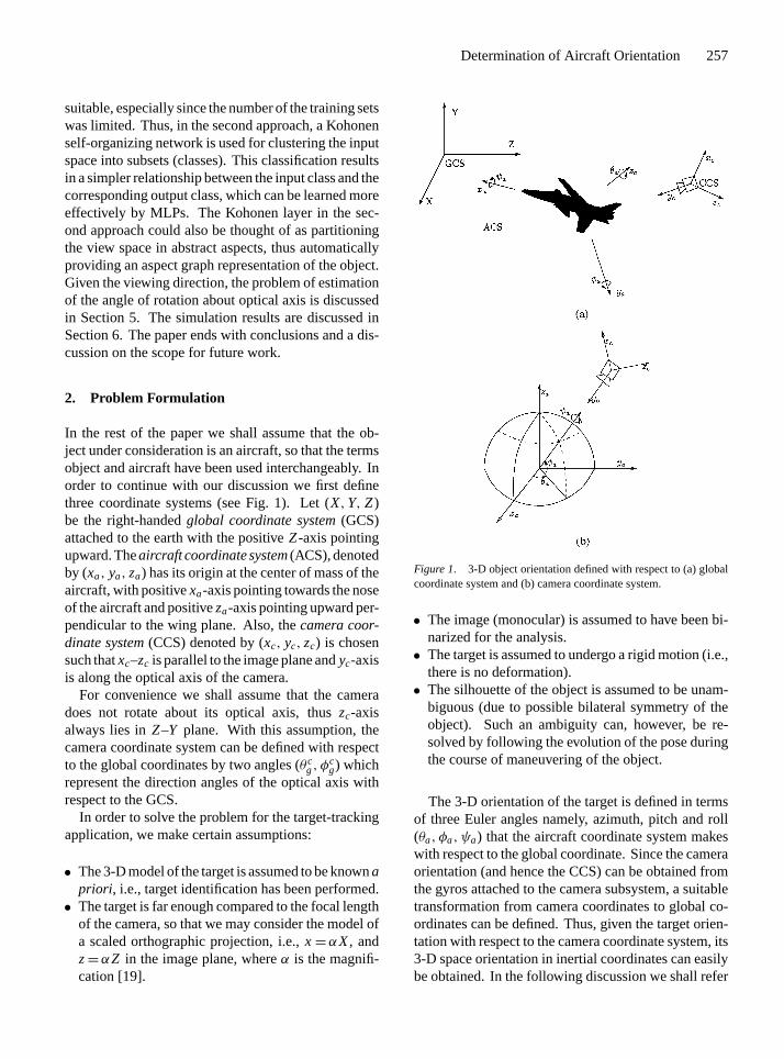
In the rest of the paper we shall assume that the ob-ject under consideration is an aircraft, so that the termsobject and aircraft have been used interchangeably. Inorder to continue with our discussion we first definethree coordinate systems (see Fig. 1). Let (X,Y, Z)be the right-handedglobal coordinate system(GCS)attached to the earth with the positiveZ-axis pointingupward. Theaircraft coordinate system(ACS), denotedby (xa, ya, za) has its origin at the center of mass of theaircraft, with positivexa-axis pointing towards the noseof the aircraft and positiveza-axis pointing upward per-pendicular to the wing plane. Also, thecamera coor-dinate system(CCS) denoted by (xc, yc, zc) is chosensuch thatxc–zc is parallel to the image plane andyc-axisis along the optical axis of the camera.
For convenience we shall assume that the cameradoes not rotate about its optical axis, thuszc-axisalways lies inZ–Y plane. With this assumption, thecamera coordinate system can be defined with respectto the global coordinates by two angles (θc
g, φcg) which
represent the direction angles of the optical axis withrespect to the GCS.
In order to solve the problem for the target-trackingapplication, we make certain assumptions:
• The 3-D model of the target is assumed to be knownapriori , i.e., target identification has been performed.• The target is far enough compared to the focal length
of the camera, so that we may consider the model ofa scaled orthographic projection, i.e.,x=αX, andz=αZ in the image plane, whereα is the magnifi-cation [19].
Figure 1. 3-D object orientation defined with respect to (a) globalcoordinate system and (b) camera coordinate system.
• The image (monocular) is assumed to have been bi-narized for the analysis.• The target is assumed to undergo a rigid motion (i.e.,
there is no deformation).• The silhouette of the object is assumed to be unam-
biguous (due to possible bilateral symmetry of theobject). Such an ambiguity can, however, be re-solved by following the evolution of the pose duringthe course of maneuvering of the object.
The 3-D orientation of the target is defined in termsof three Euler angles namely, azimuth, pitch and roll(θa, φa, ψa) that the aircraft coordinate system makeswith respect to the global coordinate. Since the cameraorientation (and hence the CCS) can be obtained fromthe gyros attached to the camera subsystem, a suitabletransformation from camera coordinates to global co-ordinates can be defined. Thus, given the target orien-tation with respect to the camera coordinate system, its3-D space orientation in inertial coordinates can easilybe obtained. In the following discussion we shall refer

P1: VBI
Journal of Mathematical Imaging and Vision KL550-04-Agarwal January 29, 1998 12:17
258 Agarwal and Chaudhuri
to the problem of estimating target orientation with re-spect to the CCS asposeestimation.The pose of the target can be defined in terms of threeangles:
1. The view of the target (θ, φ): The angles that thecamera axes make with the aircraft coordinate sys-tem. The view (0, 0) corresponds to the front viewof the aircraft. Hereθ ∈ (−π, π ], with right hemi-sphere taking positive values, whileφ ∈ [−π/2,π/2] with the top hemisphere taking positive values.
2. The rotation about the camera axis (ψ), such thata rotation of the image byψ coincides the givenimage to a standard view at that viewing direction.The standard image for any view (θ, φ) is the oneobtained with the ACS coincident with the GCS andthe CCS pointing in (θ, φ) direction.
The two bearing angles namely the elevation (θt ) andthe azimuth (φt ) can be obtained from the directioncosines of the camera optical axis (θc
g, φcg) as obtained
from the inertial navigation system and the location ofthe centroid (x, y) of the silhouette of the object. Sincethe 3-D space orientation with respect to the GCS caneasily be obtained given the pose angles (θ, φ, ψ) andthe camera coordinate angles (θc
g, φcg), in the rest of
the section we shall concentrate on the pose estimationproblem, i.e. estimating (θ, φ, ψ) from a monocular,binary image of the target.
3. Feature Extraction
In order to obtain the pose of the aircraft for a givenimage, it should be compared with the stored imagesof different targets at various orientations. Storing thewhole image of each view of the object and subsequentcomparison with the given image is physically not pos-sible due to memory and time limitations. Thus, somesimple representative features should be obtained in or-der to characterize the images of the target at differentorientations.
As we have seen, the ‘pose’ of an object is definedby (θ ,φ,ψ), where (θ ,φ) represents the viewing direc-tion of the object, andψ represents the rotation aboutthe optical axis. It may be noted that rotation about theoptical axis produces merely a rotation in the imageplane and there is no change in the shape and size ofthe image. Thus, given an image representation whichis independent of the rotation in the image plane, thesearch can be restricted to a two-dimensional space for
two angles representing the direction of view of theobject. The rotation about the optical axis can subse-quently be found [11]. Generally it is advantageous tohave an image representation which is also invariant todistance of the object from the camera, and its positionin the field of view. Thus, we seek a set of featureswhich is invariant with respect to scaling, translationand rotation in the image plane. Such a set of fea-tures is referred to asfeature vectorcorresponding to aparticular view of the object.
Many different feature vectors based on Fourier de-scriptors [43] and moment invariants [5, 11, 20, 33, 39]have the desirable properties mentioned above. Fourierdescriptors are functions of the boundary of the objectand are consequently very sensitive to the inaccuraciesaccrued during the segmentation and the edge detec-tion process. Spatial moment, in contrast, is a propertyof the mass distribution in the image. The featuresdefined in term of these are thus more robust againstsensor noise, especially for thresholded images consid-ered here [33]. Through experimental results on hand-written numerals and aircraft pictures, Belkasim et al.have shown that normalized Zernike moment invari-ants work considerably better than Hu moments [20]in terms of their discrimination power. They are alsoshown to be marginally better than the principal axismoments in that respect. However, normalized Zernikemoments are computationally more intensive. In thispaper we have employed principal axis moment invari-ant based features to characterize different views ofthe object. Other invariants may also be used withoutaffecting the solution modality.
Two-dimensional spatial moment of order(p + q)of an image functionf (x, y) is defined as
Mpq =∫ ∫ ∞
−∞xp yq f (x, y) dx dy
(p,q = 0, 1, 2 · · ·). (1)
For the binary image,f (x, y) takes value 1 if(x, y)∈object and 0 otherwise.
The invariance to translation can be achieved bycalculating moments about the center of mass of theobject. The scale invariance can be obtained by nor-malizing the moments such that the 0th order momentis unity. The normalized central moments are defined as
µ′pq = λ2+p+q∫ ∫ ∞
−∞(x− x)p (y− y)q f (x, y) dx dy
(2)
wherex=M10/M00, y=M01/M00, andλ= 1/√
M00.

P1: VBI
Journal of Mathematical Imaging and Vision KL550-04-Agarwal January 29, 1998 12:17
Determination of Aircraft Orientation 259
The rotational invariance can be obtained using asuitable combination of the central moments such thatthey contain all the information of the original momentset except the angle of rotation. Hu [20] has definedone such set of seven algebraic moment invariants oforder 3. The rotational invariants can also be obtainedby rotating all normalized central moments as definedin Eq. (2), by an angleψm such that the central momentµ11= 0. Hereψm represents the angle that the originalimage axes make with the principal axes of the best fitellipse and is defined as (see [20])
ψm= 1
2tan−1
(2µ′11
µ′20− µ′02
). (3)
We may note thatψm, as obtained above may bewith respect to either the major principal axis or theminor principal axis. However, if we ensure that theresultant principal axis momentµ20 > µ02, thenψm
represents the angle that the major principal axis of thebest fit ellipse makes with the image planex-axis. Weshould also ensureµ30 ≥ 0 so that the positive majoraxis points in the same direction in both the standardview and the given image.
The set of spatial moments calculated about the ma-jor principal axis forms a set of scale, translation androtation invariant features. With simple algebraic ma-nipulations it follows that the normalized principal axismoments can be defined in terms of the central mo-ments as [33]:
µpq =p∑
r = 0
q∑s= 0
(−1)q−s
(pr
)(qs
)(cosψm)
p−r+s
×(sinψm)q+r−sµ′p+q−r−s,r+s (4)
The invariant moments can thus be obtained from thesecentral moments with very little computational effort.
4. Estimation of the View of the Aircraft
With the change in viewing direction, the shape of theobject on the image plane changes. The feature vectoris thus dependent on the viewing direction of the object.In this section we discuss the estimation of the view-ing direction given the rotation, translation and scaleinvariant feature vector for the image.
Various algorithms have been proposed in the liter-ature to estimate the viewing direction and recognitionof a 3-D object. They include normalized quadtree rep-resentation [7], and syntactic pattern recognition [44].
The most popular among them is probably thelibraryview method[11, 42, 43]. In this approach, a set offeature vectors of dimensionn is stored in a library ofviews, where each vector is representative of a particu-lar view of the 3-D object. When an image is obtained,its corresponding feature vector is calculated. A suit-able viewing angle is assigned to the image by a searchalgorithm based on a minimum distance or ak-nearestneighbor classifier. The search can be limited over asubset of the library views if a limit on the maximumpossible change from the previously calculated orien-tation can be defineda priori [42]. The algorithm iseasily extended to more than one object by storing theviews of each object and making comparison over theresultant (n+ 1)-dimensional space [11].
The above method works reasonably well for the tar-get identification problem. However, due to the follow-ing reasons it is not suitable for accurately determiningthe target orientation in real time applications:
• Since the distance of the image feature vector to ev-ery library view (belonging to a chosen subset) hasto be calculated, the computation time can be unde-sirably large.• Due to the lack of interpolation between the library
views, for a reasonably accurate estimation of ori-entation, one has to store the library views at smallintervals. This implies a prohibitively large databaserequirement, and an increased computation time.
In the library view method, the estimation of view-ing direction is considered as a classification problem,where each view of the object forms a distinct class.Thus, there is a minimum error depending upon thenumber of classes considered over the range of viewingdirections. Wallace and Mitchell [42] have employedthe linearity property of normalized Fourier descrip-tors to interpolate between the library views and thusdefine a continuum of library projections. This yieldsbetter estimates of the orientation. However, sincethe interpolation has to be performed for each view,the algorithm is quite slow. In the following section,we take a different approach to this problem whereinthe direction of view of the aircraft is functionally re-lated to the feature vector of the object image. Thus,the view of the aircraft can directly be calculated fromthe relationship, once the feature vector for the imagehas been extracted. Two neural network topologies(NNT) are discussed in this section to solve the re-sulting functional approximation problem relating theviewing direction to the feature vector for the image.

P1: VBI
Journal of Mathematical Imaging and Vision KL550-04-Agarwal January 29, 1998 12:17
260 Agarwal and Chaudhuri
4.1. Viewing Direction as a Functionof Feature Vector
Since each element of the feature vector represents aphysical quantity (feature) of the target shape for anyspecific view of the aircraft, we could expect these fea-tures to vary smoothly with the variation in viewing an-gle of the target. Thus, each element of the feature vec-tor Ex= (x1, x2, . . . , xn) can be defined as a piece-wisesmooth function of two orientation angles (θ, φ) as:
xi = gi (θ, φ), i = 1, 2, . . . ,n. (5)
The set of functions (gi (θ, φ), i = 1, 2, . . . ,n) con-stitutes an approximate feature space representation ofthe 3-D object. We prefer calling this representationan approximate one since the set of functions may notbe complete with respect to specifying all attributes ofthe 3-D shape of the object.
The estimation of orientation can now be defined asan inverse problem, that is, given the object representa-tion gi (θ, φ) for all i , find the orientation angle (θ0, φ0)for a given feature vectorEx, xi = gi (θ, φ)|(θ0,φ0)
. Notethat gi (θ, φ) may not be monotonic over domain(θ ∈ [θ1, θ2] andφ ∈ [φ1, φ2]) and thus the inverse rela-tionship may be multivalued. However, for sufficientlymany features constituting the feature vector, we canexpect a one-to-one relationship to exist between thefeature vector and the orientation. While one feature isnot monotonic over some domain the other one couldvery well be, resolving the nonuniqueness of the esti-mate.
The problem of estimating the viewing directionis thus reduced to finding a functional relation-ship F :<n→<2, from n-dimensionalfeature vec-tor (Ex) to a two-dimensionaloutput orientation vector(Ey= (θ, φ)):
Ey=F(Ex); Ex ∈Ä ⊂ <n, Ey∈8 ⊂ <2. (6)
Rather than explicitly calculating this functional re-lationship (which can be a daunting task), we attemptto train a suitable neural network to learn the relation-ship taking advantage of the functional approximationcapability of the neural networks. In the rest of thissection, two different neural network topologies (NNT)are presented in order to obtain the relationship.
4.2. NNT-I: Multi-layer Perceptron
A multi-layer perceptron (MLP) is a feed forward netwith one or more hidden layers of nodes (neuron or
single perceptron) in between the input and the outputlayers. Each node in any layer is fully connected to eachnode in the layer below it. A sigmoidal nonlinearitygiven by fs(u)= (1+ e−βu)−1 is most popularly usedto introduce the nonlinearity at the output of each node.Hereβ is a scale factor that defines the steepness of thetransition region of the nonlinearity.
The MLP has the desired capability of not only toimplement, but also tolearnnonlinear transformationsfor functional approximation problems [21]. The net-work stores an approximate input-output relationshipin terms of its weights. At the time of training, theweights are adjusted such that the cumulative error inthe output over the training set, defined as
Jp=p∑
i=1
∣∣Eydi − Eyai
∣∣2 (7)
is minimized. Here,p is the size of the training set andthe subscriptd anda stand for the ‘desired’ and the ‘ac-tual’ network outputs, respectively. For our orientationestimation problem,n-dimensional feature vector con-stitutes the input pattern to the network. The outputof the network gives an estimate of the viewing angle(θ, φ) of the target.
The MLP solves the functional approximation prob-lem by combining simple functional units (roundedstep functions for sigmoidal nonlinearity), formed byhidden layer nodes [21]. It has been shown that a two-layer MLP is capable of forming an arbitrarily closeapproximation to any continuous nonlinear mapping[10]; however, there is no objective manner in whichto choose the number of nodes in each layer. For somecomplex mapping, the network size (number of nodesand weights) can be arbitrarily large. Moreover, sinceany error in the output affects all the network weights,a large error for some training pattern undermines theaccuracy achieved for the rest of the training set.
4.3. NNT-II: MLP with Kohonen Clustering
In light of above observations, we can expect betterresults if the complete mapping from input set (featurevector) to the output set (viewing direction) is dividedinto mappings from a suitable subset of the inputs to thecorresponding output subset. For properly chosen sub-sets, we may expect the mapping between them to besimpler than the one that exists between the completeset of inputs and the outputs. It must then be easierto train an MLP network for the resulting functionalapproximation problem for these simpler input-outputrelationships. Also, the error in the estimate for any

P1: VBI
Journal of Mathematical Imaging and Vision KL550-04-Agarwal January 29, 1998 12:17
Determination of Aircraft Orientation 261
training pattern affects only the patterns belonging toits class.
Thus, if Ä ∈ <n is the set of all feature vectorstaken at different viewing angles, for a given target,findÄi ⊂ <n, i = (1, 2, . . . ,m) such that,
Ä =m⋃
i=1
Äi and Äi ∩Ä j ={∅} for i 6= j, (8)
wherem is the number of classes formed. The subsetsneed to be disjoint without which a particular input mayfire upmore than one MLP, introducing an ambiguityin the output. Moreover,Äi should be connected. Thispartition of the view-space can be viewed as obtainingan aspect graph of the object such that each subsetÄi
represents a different general view of the object.As a consequence of the above partition of the feature
space, the nonlinear transformationF(x), gets simpli-fied intom functionals
Ey = Fi (Ex), Ex ∈Äi , Ey∈8i , i = (1, . . . ,m) (9)
where8i ⊂8 is the output subset corresponding toÄi .Having constructed the framework, we need a mech-
anism to define these clusters in a consistent manner.Kohonen self-organizing network [25] provides onesuch simple method to do this clustering. The numberof output nodes is kept equal to the number of requiredclusters. The output nodes are connected among them-selves with lateral inhibition. The weights from eachinput to a given cluster adjusts itself such that all fea-ture vectors with propertiessimilar to the vector storedat these weights are assigned to the same class. Theproperties of the feature vector to be matched are themagnitude and direction of the vector inn-dimensionalspace. Given the number of clusters to be formed andan initial guess for the weight vector, learning algo-rithm for Kohonen network automatically adjusts theelements of the weight vector in such a manner as toform m connected, nonoverlapping clusters. The stepsinvolved in training the Kohonen network may be foundin [4]. The choice of the number of clusters is madeby trial and error. The number of clusters should bequite small failing which the computational overheadincreases in the second stage (we need to train as manyMLPs). The weight vectors for the network are initial-ized such that they are oriented in the Euclidean spacerandomly around the center. This ensures that eachnode has equal likelihood of being chosen as the bestmatch in the early stages of the training, thus allowingall the output nodes to participate in the classificationprocess. A neighborhood (Ne) and a learning rate (η)
need to be chosen such that a stable classification is ob-tained. Typically,η is progressively reduced to closeto zero from an initial level of 0.2 or so. Also,Ne isinitialized to be a large number (less than the numberof clusters) and is gradually reduced to zero.
4.4. Architecture and Training for NNT-II
Once the classes have been defined by the Kohonenlayer, the functional relationship from thej th inputsubset (Ä j ) to the corresponding output subset (8 j )is trained on separate multi-layer perceptrons for eachclass with no interconnection across one another. Aschematic diagram of the proposed network architec-ture is shown in Fig. 2. Since all the MLPs are mutuallynon-interacting, the error in one region affects only theweights of the class it belongs to, and hence does notundermine the results in any other class. Moreover,the training for the MLP corresponding to each classcan be accomplished with a lesser number of nodesbecause of the simpler relationship that exists betweenthe respective input-output sets. Owing to a smallernumber of nodes in the hidden layer this topology isexpected to provide a better generalization for the un-trained data. The major steps of the algorithm to trainthe network for a given target type are summarized be-low:
(Step 0)Get the training data sets : Train-ing data consists of the feature vectors at differentviewing directions (θ, φ) sampled at a fairly regularinterval over the range of view for the given target.
Figure 2. Schematic diagram of the proposed neural networktopology.

P1: VBI
Journal of Mathematical Imaging and Vision KL550-04-Agarwal January 29, 1998 12:17
262 Agarwal and Chaudhuri
(Step 1) Kohonen clustering : Divide the inputspace in the required number of subsets. The numberof classes should be large enough so that the complexfunctional relationship is effectively simplified, atthe same time it should have a reasonable size of eachcluster so that the MLPs can be properly trained.
(Step 2) Define network architecture : As-sign a suitable number of hidden layers and thenumber of nodes for the multi-layer perceptron cor-responding to each Kohonen cluster. Each MLPnetwork is fully connected among its nodes withno interconnections between the nodes belonging todifferent clusters.
(Step 3) Train the network : The input featurevector is presented to the Kohonen layer. Koho-nen network output assigns this input to one of theclasses, sayj ∗. The input-output set is then fedonly to the multi-layer perceptron corresponding toclass j ∗. The weights for this network are updatedin exactly the same way as for a simple multi-layerperceptron [29]. The weights for no other clustersare updated.
(Step 4) Check : After enough training through thecomplete training set, a test for learning and gener-alization is made. If found unsatisfactory, the proce-dure can be repeated fromStep 2. If the results areyet not satisfactory the Kohonen clustering may haveto be repeated with an increased number of outputclasses.
The neural network, after proper training, definesthe transformation from an image feature vector to theviewing direction of the 3-D object. When the image atany arbitrary viewing direction is obtained, the featurevector is calculated and is fed to the feedforward neuralnetwork as trained above. The output of the net directlygives an approximate viewing direction.
5. Estimation of Rotation about Optical Axis
Once the viewing direction has been calculated, the ro-tation in the image plane can be found as the angle thatthe principal major axis of the image makes with thatof the standard view in that viewing direction. Thus,
ψ =ψm|image− ψm|standard, (10)
whereψm is the inclination of the major axis of thebest fit ellipse (principal axis) with respect tozc axis ofCCS.
Figure 3. Schematic diagram for the orientation estimation scheme.
In the library view methodthe angleψm|standardisstored along with the feature vector for each libraryview. Sinceψm|image can be calculated for the givenimage, the angleψ can directly be determined fromEq. (10). However, in our case the viewing directionis continuous valued. Thus, for every viewing direc-tion (θ, φ) there is a uniqueψm|standard, which must bestored. If we were to store this angle in a look up ta-ble, the retrieval of the data can be done very quickly,however, the amount of data to be stored may be quitelarge depending on the required accuracy.
In order to save memory, we define the standardorientationψm|standardas a function of the viewing di-rection. A two inputs (θ, φ), one output (ψm|standard)multi-layer perceptron is trained to store this relation-ship for each type of the target. For every estimate ofthe viewing direction (θ, φ), this MLP network givesthe corresponding estimate forψm|standard.
Figure 3 shows the schematic diagram of the com-plete system for the estimation of the orientation of thetarget in 3-D space.
6. Simulation Experiments
6.1. Results
The training and test images used in the following ex-periments have been generated from a 3-D geometricmodel of the X-29 demonstration aircraft. We now listthe design steps involved in the experiment.
• Generating Training and Test Data: For a binaryimage as considered here, views at (θ, φ) and (θ −π,−φ) differ from each other merely by a reflection.Moreover, since the aircraft is symmetric aboutx–zplane, the views at (θ, φ) and (−θ, φ) are also thesame. Thus, the range of significant views is limitedto the quarter sphere, 0≤ θ ≤ π , 0 ≤ φ ≤ π/2.However for the sake of convenience in simula-tion experiments, we limit the range of views to

P1: VBI
Journal of Mathematical Imaging and Vision KL550-04-Agarwal January 29, 1998 12:17
Determination of Aircraft Orientation 263
Figure 4. Some of the typical X-29 aircraft views.
the quarter hemisphere given by 0≤ θ ≤ π/2,0≤ φ ≤ π/2 in this study.
Figure 4 shows some of the typical views of the air-craft. The complete training set consists of 236 air-craft views, sampled uniformly at different viewingdirections covering the quarter hemisphere definedabove. Binary images are generated on a 640× 480grid for each of these views. Similarly, a set of40 test images at arbitrary angles over the quarterhemisphere is obtained to verify the generalizationachieved by the neural networks.• Calculate Moment Invariants: From each image, a
total number of eleven principal axis moment in-variants (upto fourth order moments) are calculated.Also, the values of angleψm|standardfor these imagesare stored. Higher order moments were not used be-cause they were found to be very sensitive to noiseand change in scale.
To validate our assumption of smooth variation offeatures with the change in aircraft views, and to geta visual feel of the correlation that exists betweenvarious components of the feature vector, each el-ement of the feature vector is interpolated over agrid of viewing angles, given their values over thetraining set. The gradient projection interpolationalgorithm [17] is used for the purpose. Figure 5shows the plots obtained after interpolation for someof these principal axis moments. As we can see, thefeatures vary smoothly with the viewing direction asexpected, notwithstanding the fact that the interpo-lation scheme yields aC2 function.• Normalize the Training Patterns: In order to keep the
size of the network small, a set of nine most signif-icant principal axis moments is experimentally cho-sen as the feature vector. The momentsµ40 andµ03
are dropped since the plots of these features showthat these moments do not contribute much addi-tional information, that is not already included in the
other nine features. Experimentation with and with-out µ40 and µ03 yielded almost indistinguishableresults.
All the training patterns (236 input-output sets)are now normalized with suitable mapping functionssuch that the input features take values from 0 to 1,while the output is normalized between 0.3 and 0.7.The normalization of the input in this manner ensuresthat all the features are weighted equally. If onehas anya priori knowledge about the relative meritsof individual components of the feature vector inevaluating the viewing direction, the weights to theinput could be changed suitably. The normalizationof output vector is needed to avoid the network fromgoing into saturation (sigmoidal nonlinearity at theoutput nodes goes into saturation around ‘0’ and ‘1’).• Estimation of Viewing Direction Using a Single
MLP: An MLP with two hidden layers and having8 nodes in first hidden layer and 5 in the second istrained using the complete set of 236 feature vectors.The backpropagation training algorithm as outlinedin [29] along with the momentum term has been fol-lowed for the training purposes. Training is done for9000 feeds through the feature set in random order,with the learning rateandmomentum termprogres-sively being reduced.
Figure 6 shows the error map over the training setat the end of the training. The error in each viewingdirection (θ, φ) is represented by an error vector,where ‘•’ corresponds to the true viewing direction.The magnitude of the error is thus represented by thelength of the error vector, while itsθ orφ componentcan be obtained from the direction of the vector. Theerrors are relatively high and lie mostly in the rangeof 2◦–10◦.• Estimation of Viewing Direction Using MLPs with
Kohonen Clustering: Instead of training a singleMLP to estimate the view of the aircraft, we employ

P1: VBI
Journal of Mathematical Imaging and Vision KL550-04-Agarwal January 29, 1998 12:17
264 Agarwal and Chaudhuri
Figure 5. Mesh plots of the features over the range of viewing directions.
Figure 6. Errors in estimation for the training pattern using MLP.Here ‘•’ corresponds to the true value of viewing direction while theerror in estimation is given by the length of the error vector drawnfrom •.
Kohonen clustering to first divide the input-outputmapping into many simpler mappings. The set ofnormalized feature vectors is clustered in four classesfollowing the steps as outlined in Section 4.3. Theweight vectors are initialized such that they representsome random vectors in Euclidean space, around avector of unity magnitude and all direction cosinesequal to 1/
√n, wheren= 9. Moreover, since there
are only four clusters to be made, the neighborhoodNe is taken as 0. The learning rate is progressivelyreduced from 0.2 to 0. Figure 7 shows the classes asclustered after 1500 feeds through the data.
The MLP architecture for each of the above fourclasses is decided after experimentation with differ-ent nodal arrangements. The training of the networksis accomplished following the training algorithmoutlined in Subsection 4.4. Figure 8 shows the errormap over the training set with the MLP architec-ture as indicated in the figure. An MLP architecturewith n inputs andm outputs is represented asn-p-q

P1: VBI
Journal of Mathematical Imaging and Vision KL550-04-Agarwal January 29, 1998 12:17
Determination of Aircraft Orientation 265
Figure 7. Classification of the training patterns achieved usingKohonen clustering. Here the classes 1 to 4 are given by ‘◦’, ‘ ?’‘+’ and ‘×’, respectively.
Figure 8. Error map for the training patterns using MLPs witha Kohonen layer. MLP architectures used are: class1 → 9-7-2;class2→ 9-5-2; class3→ 9-8-2; class4→ 9-8-5-2.
-· · ·-m, wherep,q, . . . are the number of nodes ineach of the hidden layers. The mode of distributionof the errors was found to be about 2◦.
To study the generalization and interpolation capa-bility of the networks, orientation estimates for thetest images are obtained with both neural networktopologies. Figure 9 shows the corresponding errormap with the two neural network topologies.•—×shows the error in estimation with topology-I, while•— shows the corresponding error with NNT-II. Theerrors in the first case were found to lie scattered in
Figure 9. Errors in the estimate for the test data (previously unseen)using both neural network topologies. Here•—× corresponds to theerror in the single MLP scheme, and•— corresponds to the samefor the MLPs with Kohonen clustering.
the range 1◦–10◦, whereas it was mostly below 4◦ inthe second case.
The performance of neural network architecture(NNT-II) was also tested with noisy input imagesand with different scaling. Two different sequencesof target motion were simulated. Figure 10 showsthe corresponding trajectories as projected on theφ–θ plane. Corresponding 3-D poses for the entiremotion sequence were recovered for the object fromits silhouettes. In order to simulate noise in theimages, the object pixels (assumed dark) lying on
Figure 10. Aircraft trajectory of two simulated paths.

P1: VBI
Journal of Mathematical Imaging and Vision KL550-04-Agarwal January 29, 1998 12:17
266 Agarwal and Chaudhuri
Table 1. Estimation error under noise and scale changes.
Trajectory 1 Trajectory 2
Error θ◦ Errorφ◦ Error θ◦ Errorφ◦
Original 3.3927 2.2856 2.0398 1.5859
Noise
(5%) 3.5895 2.8635 3.5833 2.1420
(10%) 4.3770 3.1906 3.6534 2.3342
(20%) 4.9940 3.7749 3.3182 3.4542
(30%) 5.3565 4.6607 4.7859 4.0804
Scale
(0.5) 2.9818 2.7202 3.4615 2.6260
(0.33) 4.6822 4.2728 2.5910 3.9753
(0.25) 5.1877 4.2322 4.1201 5.2775
the boundary of the silhouette are switched to back-ground intensity with a specified probability. Theexperiment was performed with varying amounts ofnoise perturbations, namely 5, 10, 20 and 30 per-cent. Similarly, the experiments were also repeatedfor both the motion data sequences with varying scalefactors. The scale is changed by subsampling the im-age by different factors, such as 2, 3 and 4. The errorvariances inθ andφ for all these cases are shown inTable 1.• Estimation of Rotation About the Optical Axis: It was
experimentally found that the variation inψm|standardfor each viewing direction is fairly smooth (exceptin small region aroundθ = 0◦, φ= 30◦. Thus, a 2input-1 output multi-layer perceptron can be trainedto capture this relation. However, the results with asingle MLP were not satisfactory [2]. Four separateMLPs were trained for each of the classes obtainedearlier with Kohonen clustering. The error in theestimation ofψm|standardobtained with this approachis shown in Fig. 11. In the figure, the error in theestimation ofψm|standardis given by the length of thesegment. The line segment pointing at 45◦ indicatespositive error, while the one at−135◦ implies neg-ative estimation error. Also, the segments endingwith an arrow sign indicate an error above 10◦.
6.2. Observations and Discussions
Our observations about the performance of the pro-posed scheme to estimate the 3-D orientation of a targetcan be summarized as follows:
Figure 11. Errors in the estimation ofψm|standardover the rangeof viewing directions. MLP architectures used in this study are:class1 → 2-5-2-1; class2 → 2-4-2-1; class3 → 2-3-1; class4 →2-3-1.
1. The error in the estimation of viewing angle is verysmall in most of the regions in the case of networktopology-II (i.e., with Kohonen clustering). Also,the errors with this topology are much smaller com-pared to that obtained with a single network. Thisclearly shows the advantage of using the Kohonenclustering in order to divide the functional approx-imation problem into many simpler ones.
2. The error in the estimates ofθ whenφ is close to90◦ is found to be quite large. But this error is ex-pected as, in this region, the variation in the featurevector withθ is very small (see Fig. 5). The rea-son for this small variation in feature vector overthis region can be seen easily. The longitude lines(θ = constant) near the pole (φ= 90◦) are very closetogether, thus, a change inθ does not result in anappreciable change in the projection of the aircraft.Hence the feature vectors are quite similar. How-ever, the error in estimatingθ is tolerable in thisregion, since this error gets offset by the resultingestimate ofψ . For example atφ= 90◦ (top view ofthe aircraft) feature vectors for allθ are the same.Thus the aircraft pose given by (θ, φ)= (0◦, 90◦)andψ = 0◦ is the same as that corresponding to(θ, φ)= (45◦, 90◦) andψ = −45◦. Similarly a rel-atively large error occurs in the estimation of view-ing angle in the region given by 75◦ ≤ θ ≤ 90◦,

P1: VBI
Journal of Mathematical Imaging and Vision KL550-04-Agarwal January 29, 1998 12:17
Determination of Aircraft Orientation 267
0◦ ≤ φ ≤ 15◦. This error is due to the fact thatthe feature vector is not discriminatory enough withrespect to change in viewing angles over this do-main (see Fig. 5). This may be attributed to thegeometry of the aircraft in this region (side view).Inclusion of higher order moments may not alleviatethis problem as they are more sensitive to noise.
3. From Fig. 9, we can see that the neural networktopology with Kohonen clustering yields good esti-mates of the viewing direction even for the untrainedviews. This shows that the network has, indeed,learnt the input-output functional relationship ratherthan just memorizing the training patterns. We sug-gest the use of this architecture for the estimation ofthe view of the aircraft.
4. The error in the estimation ofψm|standardis reason-ably small in most cases. However, due to a suddenchange inψm|standardat aroundθ = 0◦ andφ= 30◦,the error in the vicinity of this region is undesir-ably large (as much as 25◦). The reason for thissudden change is that the best fit ellipse in this re-gion is almost circular, thus the principal axes nolonger bear any meaning. At a particular view ofthe aircraft (this will be different for different targettypes), the major principal axis changes from be-ing perpendicular to the fuselage to around the axisof the fuselage. When this transition takes place itbecomes difficult to train the network.
5. Experiments were also performed on noisy silhou-ettes of the object, and the results were found to beof good accuracy. The increase in error variance forthe pose angles is quite marginal with the increase inperturbations of the silhouette. Similarly, the effectof scaling (i.e., reduction in pixel resolution) wasalso found to be quite gradual during the sensitiv-ity analysis of the proposed technique. Hence, themethod can be used for quite accurate results evenunder varied imaging conditions.
7. Conclusions
A neural network approach to solving the problem ofestimating the 3-D orientation of an aircraft, given itsmonocular, scaled orthographic, binary image fromany arbitrary viewing angle, has been presented in thispaper. The estimation of the orientation is modeledas a functional approximation problem. Two differ-ent neural network topologies to capture this com-plex nonlinear relationship have been discussed. Thecomparison of the results obtained with these neural
network topologies suggests that a substantial improve-ment in the functional approximation can be achievedby clustering the input space in a suitable number ofsubsets and then training separate multi-layer percep-trons for each of these clusters.
It may be interesting to compare the proposed tech-nique with the library view method with interpolationcapabilities. The Kohonen clustering process of split-ting the input space is equivalent to determining thecorresponding closest library view and the MLP out-put corresponds to the interpolation scheme. However,the number of clusters being much smaller comparedto the number of library views, the proposed techniquerequires less storage but emphasizes more on the accu-racy of the interpolation process by the MLP unit.
The proposed orientation estimation system can eas-ily be implemented for real time applications in targettracking. Once the network is trained, it takes only afraction of a second on a workstation (we used an alpha-400 machine) to obtain the pose information, given thesilhouette of the aircraft. We plan to use the pose in-formation thus obtained in conjunction with the rangeand bearing information to develop a target-trackingsystem for improved accuracy. It may also constitutea building block in an object-identification algorithm.Moreover, since this technique does not need any ofthe time-consuming edge-detection routines, it can beemployed in various industrial automation and roboticapplications where the orientation estimation and/orobject identification of an isolated object need be done,such as in a vision-guidedpick-and-placerobot.
A closer look at the error map obtained with NNT-IIreveals that a relatively large estimation error is ob-tained at the boundary of the clusters. This suggests apossible use of overlapping clusters at the classificationlevel. Also, we may note that the clustering of inputfeature space results in a simpler input-output relation-ship only if each of the input and its correspondingoutput classes form a connected set. For the Koho-nen clustering algorithm, the input clusters are alwaysconnected, however the same cannot be said of the re-sultant clustering in the output space. For the presentexperiments, the output clusters are indeed connected(Fig. 7), however more work needs to be done in thisregard. In the present paper we have considered onlystatic views of the target for the estimation of the orien-tation. The dynamics of the maneuvering target has notbeen considered in this study. We are currently lookinginto ways of incorporating the evolution of pose an-gles with time while estimating the orientation for animproved performance.

P1: VBI
Journal of Mathematical Imaging and Vision KL550-04-Agarwal January 29, 1998 12:17
268 Agarwal and Chaudhuri
Acknowledgments
The authors wish to gratefully acknowledge the sug-gestions from the referees that have greatly improvedthe presentation of this paper.
References
1. M.A. Abidi and R.C. Gonzalez, “The use of multisensor data forrobotic applications,”IEEE Trans. on Robotics and Automation,Vol. 6, pp. 159–177, 1990.
2. S. Agarwal, “Imaging sensor based target tracking, guidanceand control,” M.Tech. Dissertation, Department of ElectricalEngineering, IIT Bombay, 1993.
3. D. Andrisani, F.P. Kuhl, and D. Gleason, “A nonlinear track-ing using attitude measurements,”IEEE Trans. Aero. ElectronicSystems, Vol. AES-22, pp. 533–538, 1986.
4. R. Beale and T. Jackson,Neural Computing: An Introduction,Adam Hilger, Brisol, 1990.
5. S.O. Belkasim, M. Shridhar, and M. Ahmadi, “Pattern recog-nition with moment invariants: A comparative study and newresults,”Pattern Recognition, Vol. 24, pp. 1117–1138, 1991.
6. Z. Chan and S.Y. Ho, “Computer vision for robust 3-D air-craft recognition with fast library search,”Pattern Recognition,Vol. 24, pp. 375–390, 1991.
7. C.H. Chien and J.K. Aggarwal, “A normalized quadtree rep-resentation,”Comput. Vision, Graphics and Image Process,Vol. 26, pp. 331–346, 1984.
8. R.T. Chin and C.R. Dyer, “Model based recognition in robotvision,” ACM Computing Surveys, Vol. 18(1), pp. 68–108,1986.
9. J.R. Cloutier, J.H. Evers, and J.J. Feeley, “Assessment of air-to-air missile guidance and control technology,”IEEE ControlSystem Magazine, Vol. 9, pp. 27–34, 1989.
10. G. Cybenko, “Approximation by superposition of a sigmoidalfunction,” Mathematics of Control, Signal, and Systems, Vol. 2,pp. 303–314, 1989.
11. S.A. Dudani, K.J. Breeding, and R.B. McGhee, “Aircraft iden-tification by moment invariants,”IEEE Trans. on Computers,Vol. C-26, pp. 39–45, 1977.
12. D.W. Eggert, K.W. Bowyer, C.R. Dyer, H.I. Christensen, andD.B. Goldfof, “The scale space aspect graph,”IEEE Trans.Pattern Analysis and Machine Intelligence, Vol. 15, No. 11,pp. 1114–1130, 1993.
13. O. Faugeras, A. Pentland, J.L. Mundy, R. Jain, N. Ahuja, C.Dyer, K. Ikeuchi, and K. Bowyer, “Why aspect graphs are not(yet) practical for computer vision,”CVGIP: Image Understand-ing, Vol. 55, No. 2, pp. 212–218, 1992.
14. D. Forsyth, J.L. Mundy, A. Zisserman, C. Coelho, A. Heller,and C. Rothwell, “Invariant descriptors for 3-D object recog-nition and pose,”IEEE Trans. Pattern Analysis and MachineIntelligence, Vol. 13, No. 10, pp. 971–991, 1991.
15. D. Forsyth, J.L. Mundy, A. Zisserman, and C. Rothwell, “Rec-ognizing rotationally symmetric surfaces from their outlines,” inProc. European Conf. Computer Vision, Santa Margherita Lig-ure, Italy, 1992, pp. 639–647.
16. Z. Gigus, J. Canny, and R. Seidel, “Efficiently computing andrepresenting aspect graphs of polyhedral objects,”IEEE Trans.Pattern Analysis and Machine Intelligence, Vol. 13, No. 6,pp. 542–551, 1991.
17. W.E.L. Grimson,From Images to Surfaces: A ComputationalStudy of the Human Early Visual System, MIT Press: Cam-bridge, 1981.
18. W.E.L. Grimson, D.P. Huttenlocker, and T.D. Alter, “Recogniz-ing 3D objects from 2D images: An error analysis,” inProc.IEEE Conf. Computer Vision and Pattern Recognition, Cham-paign, IL, 1992, pp. 316–321.
19. B.K.P. Horn,Robot Vision, MIT Press: Cambridge, 1986.20. M.K. Hu, “Visual pattern recognition by moment invariants,”
IRE Trans. Info. Theory, Vol. IT-8, pp. 179–187, 1962.21. D.R. Hush and B.G. Horne, “Progress in supervised neural net-
works, what’s new since Lippmann?,”IEEE Signal ProcessingMagazine, Vol. 10, pp. 8–37, 1993.
22. H.G. Hutchins and D.D. Sworder, “Image fusion algorithms fortracking maneuvering targets,”AIAA Journal of Guid. and Con-trol, Vol. 15, pp. 175–184, 1992.
23. D. Huttenlocher and S. Ullman, “Recognizing solid objects byalignment with an image,”Int. J. Comp. Vis., Vol. 5, No. 2,pp. 195–212, 1990.
24. J.D. Kendrick, P.S. Maybeck, and J.G. Reid, “Estimation ofaircraft target motion using orientation measurements,”IEEETrans. Aero. Electro. Systems, Vol. AES-17, pp. 254–259, 1981.
25. T. Kohonen, Self-Organization and Associative Memory,Springer-Verlag: Berlin, 1984.
26. R. Krishnan, H.J. Sommer III, and P.D. Spidaliere, “Monocularpose of a rigid body using point landmarks,”CVGIP: ImageUnderstanding, Vol. 55, No. 3, pp. 307–316, 1992.
27. Y. Lamdan, J.T. Schwartz, and H.J. Wolfson, “Affine invariantmodel-based object recognition,”IEEE Trans. Robotics and Au-tomation, Vol. 6, No. 5, pp. 578–589, 1990.
28. C.C. Lefas, “Algorithm for Improved, heading assisted, ma-neuver tracking,”IEEE Trans. Aero. and Electronic Systems,Vol. AES-21, pp. 351–359, 1985.
29. R.P. Lippmann, “An introduction to computing with neural nets,”IEEE Acoustics, Speech and Signal Process. Magazine, Vol. 4,pp. 4–21, 1987.
30. D.G. Lowe,Perceptual Organization and Visual Recognition,Kluwer Academic Publishers: Hingham, MA, 1985.
31. Y. Moses and S. Ullman, “Limitations of nonmodel-based recog-nition schemes,” inProc. European Conf. Computer Vision,Santa Margherita Ligure, 1992, pp. 820–828.
32. N.P. Papanikolopoulos, P.K. Khosla, and T. Kanade, “Visualtracking of a moving target by a camera mounted on a robot: Acombination of control and vision,”IEEE Trans. Robotics andAutomation, Vol. 9, pp. 14–36, 1993.
33. A.P. Reeves, R.J. Prokop, S.E. Andrews, and F.P. Kuhl, “Three-dimensional shape analysis using moments and Fourier descrip-tors,” IEEE Trans. on Pattern Anal. Mach. Intell., Vol. PAMI-10,pp. 937–943, 1988.
34. C. Rothwell, A. Zisserman, J. Mundy, and D.A. Forsyth, “Ef-ficient model library access by projective invariant indexingfunction,” Proc. IEEE Conf. Computer Vision and PatternRecognition, Champaign, IL, 1992, pp. 109–114.
35. W.B. Seales and C.R. Dyer, “Viewpoint from occluding con-tour,” CVGIP: Image Understanding, Vol. 55, No. 2, pp. 198–211, 1992.
36. D.D. Sworder and R.G. Hutchins, “Maneuver estimation usingmeasurements of orientation,”IEEE Trans. on Aero. and Elec-tronic Systems, Vol. AES-26, pp. 625–638, 1990.
37. D.D. Sworder, R.G. Hutchins, and M. Kent, “Utility of imagingsensors in tracking systems,”Automatica, Vol. 29, pp. 445–450,1993.

P1: VBI
Journal of Mathematical Imaging and Vision KL550-04-Agarwal January 29, 1998 12:17
Determination of Aircraft Orientation 269
38. C.H. Teh and R.T. Chin, “On image analysis by the method ofmoments,”IEEE Trans. Pattern Anal. Mach. Intell., Vol. PAMI-10, pp. 496–513, 1988.
39. M. Teague, “Image analysis via the general theory of mo-ments,” J. Optical Society of America, Vol. 70, pp. 920–930,1980.
40. D.W. Thompson and J.L. Mundy, “Three-dimensional modelmatching from an unconstrained viewpoint,” inProc. IEEE Int.Conf. on Robotics and Automation, Raleigh, NC, 1987, pp. 208–220.
41. S. Ullman and R. Basri, “Recognition by linear combinationof models,”IEEE Trans. Pattern Analysis and Machine Intelli-gence, Vol. 13, No. 10, pp. 992–1006, 1991.
42. T.P. Wallace and O.R. Mitchell, “Analysis of three dimensionalmovement using Fourier descriptors,”IEEE Trans. Pattern Anal.Mach. Intell., Vol. PAMI-2, pp. 583–588, 1980.
43. T.P. Wallace and P.A. Wintz, “An efficient three-dimensionalaircraft recognition algorithm using normalized Fourier descrip-tors,” Comput. Graphics and Image Process., Vol. 13, pp. 99–126, 1980.
44. K.C. You and K.S. Fu, “Distorted shape recognition using at-tributed grammars and error correcting technique,”Comput.Graphics and Image Process., Vol. 13, pp. 1–16, 1980.
Sanjeev Agarwalreceived his Integrated M.Tech. degree in elec-trical engineering from the Indian Institute of Technology, Bombay
in 1993. He is currently pursuing his Ph.D. degree at the Universityof Missouri, Rolla. His research interests include computer vision,invariant theory, neural networks, artificial intelligence and controltheory.
Subhasis Chaudhuriwas born in Bahutali, India. He received hisB.Tech. degree in electronics and electrical communication engi-neering from the Indian Institute of Technology, Kharagpur in 1985.He received the M.S. and the Ph.D. degrees, both in electrical en-gineering, respectively, from the University of Calgary, Canada andthe University of California, San Diego. He joined IIT, Bombayin 1990 and is currently serving as an associate professor. He hasalso served as a visiting professor at the University of Erlangen-Nuremberg, Germany during the summer of 1996. He is a fellowof the Alexander von Humboldt Foundation. His research interestsinclude image processing and computer vision, pattern recognitionand biomedical signal processing.