detector de presencia empotrable kdp8 2h / 3h · incadescente de alto voltaje : 1000w máx....
TRANSCRIPT

KDP8 2H / 3H
ww
w.g
rup
otem
per
.com
Detector de presencia empotrable en caja de mecanismos
Motion detector wall switch

2Manual de instrucciones | www.grupotemper.com
KDP8 - Detector 2/3 hilosDetector de presencia empotrable en caja de mecanismos
Contents
Technical specifications 13
Package contents 15
Product description 15
Installation and wiring 16
Operation 17
Troubleshooting 18

3Manual de instrucciones | www.grupotemper.com
KDP8 - Detector 2/3 hilosDetector de presencia empotrable en caja de mecanismos
Especificaciones técnicasAlimentación 220 - 240V~50Hz
Carga KDP8-2H:Incandescente: 40 - 400W max.Incadescente de alto voltaje: 40 - 400W max.KDP8-3H: 8A máx (cos φ=1) μIncandescente: 1600W max.Incadescente de alto voltaje : 1000W máx.Fluorescente: 300VA max. (Sin compensar)Incadescente de bajo voltaje: 300VA max. (Sin compensar)Motor : 1/10 HP.
Ángulo de detección 180º
Altura de montaje 0.8 - 1.2M
Nivel crepuscular Ajustable desde 5LUX - ∞
Temporizador Ajustable desde 6s - 12min.
Área de deteccío 8m mov. directo, 4.5m mov. lateral.
Ajuste manual MANUAL ON / AUTO / MANUAL OFF.
temperatura de funcionamiento
0ºC a +45ºC
Grado de protección IP20
PrecauciónPor protección, en el cableado de la carga I debe instalarse un interruptor (250VCA,10A) de tipo C de acuerdo con la norma EN60898-1.Por protección, en el cableado de la carga II debe instalarse un interruptor (250VCA,6A) de tipo C de acuerdo con la norma EN60898-1.No instalar sobre una superficie conductora.Procure no abrir a menudo la carcasa protectora.Apague el detector para cambiar las fuentes de luz.Algunas marcas de bombillas pueden estallar y causar picos de tensión, dañando el detector sin posibilidad de reparación.

4Manual de instrucciones | www.grupotemper.com
KDP8 - Detector 2/3 hilosDetector de presencia empotrable en caja de mecanismos
La instalación y el montaje de equipos eléctricos siempre debe ser llevada a cabo por electricistas cualificados.
Contenido del embalaje
Icono
ArtículoKDP8-2H KDP8-3H Etiqueta para la
lenteManual
Detector
Cantidad 1 1 1
Descripción del productoEl KDP8 es un detector de pared con un interruptor que le permite controlar la luz. Se trata de un aparato para uso exclusivo en interiores. Es ideal para espacios no muy grandes, tiendas, oficinas, hogares, etc.
Características• Amplia cobertura en abanico que llega hasta los 8m.• Gran ángulo de detección que cubre un área de 180º sin zonas muertas.• Varios controles para los diferentes tipos de carga, luz incandescente, luz
fluorescente y luz halógena de alta o baja tensión.• Tres modos regulables TIME, LUX y METER para ajustar el campo de visión
y controlar el tiempo.• Diseño patentado en forma de gancho para una sencilla y rápida
instalación.• Diseño flexible en control paralelo con la carga .• La etiqueta de lente suministrada le permite minimizar o bloquear la zona
de detección según sus deseos.• Sistema fotocelular de ahorro de energía que le permite un funcionamiento
automático por la noche y su desactivación durante el día.• Su marco de 50mmx50mm se ajusta a la mayoría de las medidas
estándares europeas de interruptores, lo que facilita su instalación.• Bloque de terminales con agarre de tornillos que permite realizar las
conexiones de manera fácil y segura.

5Manual de instrucciones | www.grupotemper.com
KDP8 - Detector 2/3 hilosDetector de presencia empotrable en caja de mecanismos
• Control manual adicional ON/AUTO/OFF para un diseño estético único y de vanguardia.
• Conexión del conmutador de dos vías para el control de la luz en las escaleras de paso.
Dimensiones
ComponentesLa FIG.2 nos muestra los distintos componentes del KDP8. Las medidas del interior del marco de plástico son 50x50mm y puede ser reemplazado por cualquier otro marco de plástico de las mismas dimensiones que siga los estándares europeos.
5080
31.5
63
50 80
Parte trasera
Marco plástico
Placametálica
Caja depotencia

6Manual de instrucciones | www.grupotemper.com
KDP8 - Detector 2/3 hilosDetector de presencia empotrable en caja de mecanismos
Instalación y conexionesAntes de instalar el detector desconecte la alimentación. Lea este manual de instrucciones al completo antes de comenzar la instalación.
Selección del lugar de instalaciónÁrea de detecciónSu zona de detección puede alcanzar los 8 metros de diámetro y 180º. (Ver FIG.3).
Algunos consejos útiles para la instalaciónDebido a la sensibilidad del sensor ante los cambios de temperatura, evite las siguientes condiciones. (Ver FIG.4-A & FIG.4-B):• Evite dirigir el detector hacia objetos que pudieran moverse con el viento
como las cortinas, plantas de cierta altura, árboles pequeños, etc.• Evite dirigir el sensor hacia zonas u objetos de superficie muy reflectante
como espejos, monitores, etc.• No instale el detector cerca de fuentes de calor tales como respiraderos
de calefacción, de aire acondicionado, calefacciones, luces, etc.
Vista lateral Vista superior

7Manual de instrucciones | www.grupotemper.com
KDP8 - Detector 2/3 hilosDetector de presencia empotrable en caja de mecanismos
Preste atención a la dirección de paso cuando realice las pruebas. (Ver FIG.5).
Diagramas de conexiónEspecificaciones de los cables: 0.35mm2 min. (26AWG). 2.0mm2 máx. (14AWG).
KDP8-2HCableado de interruptor de pared sencillo:Este tipo de conexión es exclusivo para un uso manual del sensor; se puede realizar utilizando un pulsador (ver FIG.6-A) o con un interruptor manual (ver FIG.6-B).
Mayor sensibilidad al movimientoa través del patrón
Menor sensibilidad al movimientohacia el detector
KDP8-2H
KDP8-2HPulsador
Interruptormanual

8Manual de instrucciones | www.grupotemper.com
KDP8 - Detector 2/3 hilosDetector de presencia empotrable en caja de mecanismos
La FIG.7 muestra la instalación de un sensor en lugar de un circuito conmutado:Consulte el siguiente diagrama para realizar las conexiones del KDP8, que incluye un cable puente o jumper además del interruptor manual. Una vez hayamos conectado la luz y preseleccionado el tiempo de duración, ésta se encenderá bien pulsando el interruptor manual o activando el sensor en la posición "ON".
La FIG.8 muestra el diagrama de conexión de dos detectores en lugar de un ciscuito conmutado:• Cualquiera de los dos detectores puede activar la iluminación.
KDP8-2H
Interruptor de controlremoto
Jumper
KDP8-2H KDP8-2H
9Manual de instrucciones | www.grupotemper.com
KDP8 - Detector 2/3 hilosDetector de presencia empotrable en caja de mecanismos
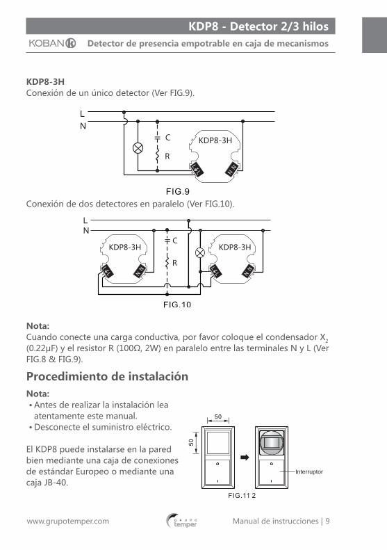
KDP8-3HConexión de un único detector (Ver FIG.9).
Conexión de dos detectores en paralelo (Ver FIG.10).
Nota:Cuando conecte una carga conductiva, por favor coloque el condensador X2 (0.22μF) y el resistor R (100Ω, 2W) en paralelo entre las terminales N y L (Ver FIG.8 & FIG.9).
Procedimiento de instalaciónNota:• Antes de realizar la instalación lea
atentamente este manual.• Desconecte el suministro eléctrico.
El KDP8 puede instalarse en la pared bien mediante una caja de conexiones de estándar Europeo o mediante una caja JB-40.
KDP8-3H
KDP8-3H KDP8-3H
Interruptor
10Manual de instrucciones | www.grupotemper.com
KDP8 - Detector 2/3 hilosDetector de presencia empotrable en caja de mecanismos
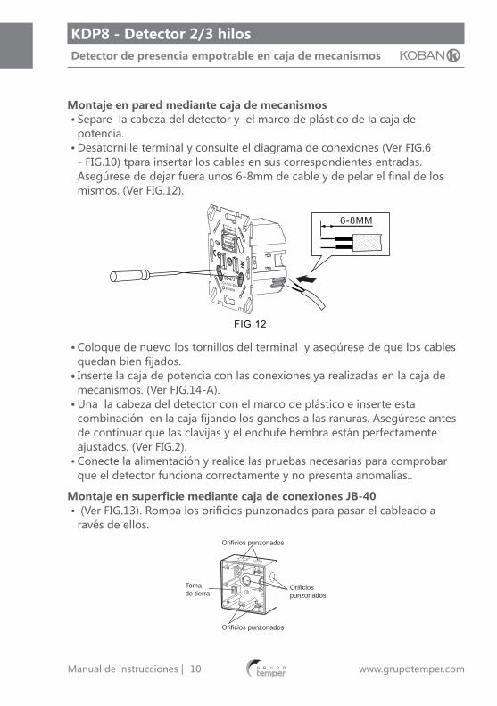
Montaje en pared mediante caja de mecanismos• Separe la cabeza del detector y el marco de plástico de la caja de
potencia.• Desatornille terminal y consulte el diagrama de conexiones (Ver FIG.6
- FIG.10) tpara insertar los cables en sus correspondientes entradas. Asegúrese de dejar fuera unos 6-8mm de cable y de pelar el final de los mismos. (Ver FIG.12).
• Coloque de nuevo los tornillos del terminal y asegúrese de que los cables quedan bien fijados.
• Inserte la caja de potencia con las conexiones ya realizadas en la caja de mecanismos. (Ver FIG.14-A).
• Una la cabeza del detector con el marco de plástico e inserte esta combinación en la caja fijando los ganchos a las ranuras. Asegúrese antes de continuar que las clavijas y el enchufe hembra están perfectamente ajustados. (Ver FIG.2).
• Conecte la alimentación y realice las pruebas necesarias para comprobar que el detector funciona correctamente y no presenta anomalías..
Montaje en superficie mediante caja de conexiones JB-40• (Ver FIG.13). Rompa los orificios punzonados para pasar el cableado a
ravés de ellos.Orificios punzonados
Orificiospunzonados
Orificios punzonados
Tomade tierra
11Manual de instrucciones | www.grupotemper.com
KDP8 - Detector 2/3 hilosDetector de presencia empotrable en caja de mecanismos
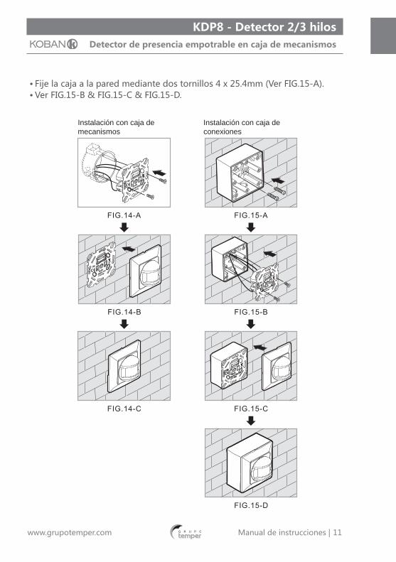
• Fije la caja a la pared mediante dos tornillos 4 x 25.4mm (Ver FIG.15-A). • Ver FIG.15-B & FIG.15-C & FIG.15-D.
Instalación con caja de mecanismos
Instalación con caja de conexiones
12Manual de instrucciones | www.grupotemper.com
KDP8 - Detector 2/3 hilosDetector de presencia empotrable en caja de mecanismos
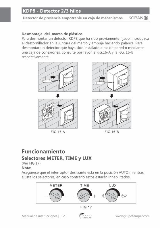
Desmontaje del marco de plásticoPara desmontar un detector KDP8 que ha sido previamente fijado, introduzca el destornillador en la juntura del marco y empuje haciendo palanca. Para desmontar un detector que haya sido instalado a ras de pared o mediante una caja de conexiones, consulte por favor la FIG.16-A y la FIG. 16-B respectivamente.
FuncionamientoSelectores METER, TIME y LUX(Ver FIG.17).Nota:Asegúrese que el interruptor deslizante está en la posición AUTO mientras ajusta los selectores, en caso contrario estos estarán inhabilitados.
13Manual de instrucciones | www.grupotemper.com
KDP8 - Detector 2/3 hilosDetector de presencia empotrable en caja de mecanismos
Selector METER• Ajuste el selector "METER" en la posición "-" para obtener el menor campo
de visión posible.• Ajuste el selector "METER" en la posición "+" para obtener el mayor campo
de visión posible.• Ajuste el selector "METER" entre las posiciones "-" y "+" según el campo
de visión que desee.Selector TIME• Ajuste el selector "Time" en la posición "-" para mínimo tiempo de retardo
(5 segundos).• Ajuste el selector "Time" en la posición "+" para máximo tiempo de retardo
(10 minutos).• Para realizar los ajustes de tiempo según sus necesidades, coloque el
selector entre las posiciones "-" y "+".Selector LUX• Coloque el selector Lux en la posición . El valor LUX será igual a 5Lux. En
esta posición el detector no reaccionará ante el movimiento ya que la luz ambiente siempre será más intensa que 5Lux.
• Coloque el selector Lux en la posición de máximo valor de LUX. El detector responderá ante el movimiento sea cual sea el nivel de luz.
• Colocando el selector en alguna de las posiciones intermedias ajustará el nivel de LUX a sus deseos.
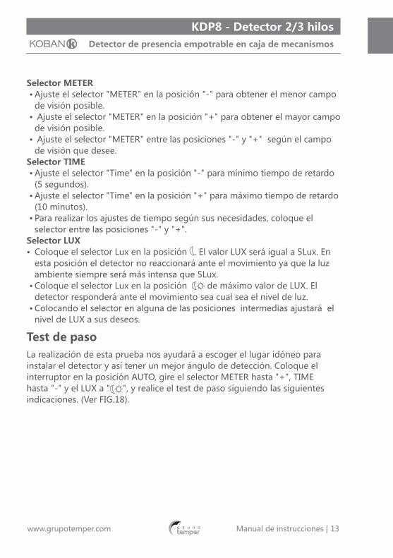
Test de pasoLa realización de esta prueba nos ayudará a escoger el lugar idóneo para instalar el detector y así tener un mejor ángulo de detección. Coloque el interruptor en la posición AUTO, gire el selector METER hasta "+", TIME hasta "-" y el LUX a " ", y realice el test de paso siguiendo las siguientes indicaciones. (Ver FIG.18).

14Manual de instrucciones | www.grupotemper.com
KDP8 - Detector 2/3 hilosDetector de presencia empotrable en caja de mecanismos
Procedimiento del test de paso• Encienda el detector.• Camine desde fuera del área de cobertura, una vez
el detector se active el LED y la carga se encenderán durante 6 segundos.
• Ajuste el selector METER hasta la cobertura deseada.• Ajuste el selector TIME para cambiar el tiempo de
retardo.• Consulte el apartado "Uso de las etiquetas de lente",
para cambiar el ángulo y rango de detección mediante las mismas.• Repita estos pasos hasta alcanzar los valores deseados.• Ponga atención a la dirección de paso mientras realiza el test. (Ver FIG.5).
Interruptor de funcionamiento manualAUTO : posición central, el detector funcionará en modo AUTO.OFF : posición izquierda, el detector funcionará en modo OFF, la iluminación estará permanentemente desconectada.ON : posición derecha, el detector funcionará en modo ON, la iluminación estará permanentemente conectada. (Ver FIG.19).
Inicio Final

15Manual de instrucciones | www.grupotemper.com
KDP8 - Detector 2/3 hilosDetector de presencia empotrable en caja de mecanismos
Nota: no quite el interruptor deslizante (Ver FIG.20).
Uso de las etiquetas de lenteLas etiquetas suministradas se utilizan para reducir el rango de detección. (Ver FIG.21).

16Manual de instrucciones | www.grupotemper.com
KDP8 - Detector 2/3 hilosDetector de presencia empotrable en caja de mecanismos
Resolución de problemas.
Problema Posible causa Solución sugerida
La carga no se enciende
1.Cableado incorrecto.2.La carga está estropeada.3.El ajuste METER es demasiado corto.4.El interruptor deslizante está en modo OFF.
1. Compruebe que la alimentación y la carga está conectados correctamente.2.Cambie la carga estropeada por una nueva.3.Ajuste el selector METER a la posición "+".4.Coloque el interruptor en las posiciones AUTO u ON.
La carga no se apaga
1.El ajuste TIME es demasiado largo, el detector está activado continuamente.2.Hay una posible interferencia.3.Cableado incorrecto.
1.Ajuste el selector TIME a la posición "-" .2.Manténgase fuera de la zona de cobertura del detector cuando realice la prueba.3.Compruebe que la carga y los cables están conectados correctamente.
El pulsador no funciona
1.Cableado incorrecto.2.Pulsador estropeado.
1.Compruebe que el pulsador está conectado entre T y L.2.Cambie el pulsador.
Interferencias que activan el detector
Puede que dentro de la zona de cobertura haya fuentes de calor, objetos reflectantes u objetos que puedan ser movidos por el viento.
Evite colocar el detector frente a fuentes de calor como aire acondicionado, ventiladores eléctricos, estufas u objetos muy reflectantes. Compruebe que ningún objeto sensible de ser movido por el viento se encuentra en su zona de detección.

17Manual de instrucciones | www.grupotemper.com
KDP8 - Detector 2/3 hilosDetector de presencia empotrable en caja de mecanismos
Nota:Do not attempt to open or repair the unit without qualified electrician while it is malfunctioned.Bajo las siguientes condiciones medioambientales, el detector puede tener una menor sensibilidad:• En noches de mucha niebla, la humedad que se puede acumular en las
lentes puede restar sensibilidad al aparato.• En los días muy calurosos la menor sensibilidad se deberá a que la
temperatura corporal se acercará a la ambiental.• En días de mucho frío, la cantidad de ropa que nos ponemos y
especialmente si nos tapamos la cara, evitamos desprender calor corporal y al detector le será más difícil captar nuestra presencia.
• Limpieza: utilice únicamente un paño seco. El uso de jabones y paños ásperos, podrían dañar la lente del detector.
18Instructions manual | www.grupotemper.com
KDP8 - 2/3 wires detectorMotion detector wall switch
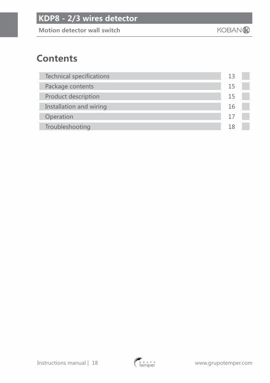
Contents
Technical specifications 13
Package contents 15
Product description 15
Installation and wiring 16
Operation 17
Troubleshooting 18

19Instructions manual | www.grupotemper.com
KDP8 - 2/3 wires detectorMotion detector wall switch
Technical specificationsRated Voltage 220 - 240V~50Hz
Load KDP8-2H:Incandescent Lamp: 40 - 400W max.HV Halogen Lamp : 40 - 400W max.KDP8-3H: 8A max (cos φ=1) μIncandescent Lamp: 1600W max.HV Halogen Lamp : 1000W max.Fluorescent Lamp : 300VA max. (uncompensated)LV Halogen Lamp : 300VA max. (uncompensated)Motor : 1/10 HP.
Detection Angle 180º
Mounting Height 0.8 - 1.2M
LUX Adjustment Adjustable from 5LUX - ∞
TIME Adjustment Adjustable from 6sec - 12min.
Detection Area 8M in frontward, 4.5M in sideward.
Manual Switch MANUAL ON / AUTO / MANUAL OFF.
Operating temperature
0ºC to +45ºC
EnvironmentalProtection
IP20
CautionA circuit breaker (250VAC, 10A) type C according to EN60898-1 of loadⅠshall be installed in the fixed wiring for protection.A circuit breaker (250VAC, 6A) type C according to EN60898-1 of loadⅡshall be installed in the fixed wiring for protection.Do not mount on conductive surface.Do not open the enclosure frequently.Turn off power when change the light sources.High in-rush current would be caused when bulbs of certain brands burned which might damage the unit permanently.
20Instructions manual | www.grupotemper.com
KDP8 - 2/3 wires detectorMotion detector wall switch
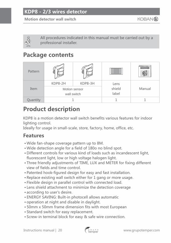
All procedures indicated in this manual must be carried out by a professional installer.
Package contents
Pattern
Item
KDP8-2H KDP8-3H Lensshieldlabel
ManualMotion sensorwall switch
Quantity 1 1 1
Product descriptionKDP8 is a motion detector wall switch benefits various features for indoor lighting control.Ideally for usage in small-scale, store, factory, home, office, etc.
Features• Wide fan-shape coverage pattern up to 8M.• Wide detection angle for a field of 180o no blind spot.• Different controls for various kind of loads such as incandescent light,
fluorescent light, low or high voltage halogen light.• Three friendly adjustments of TIME, LUX and METER for fixing different
view of fields and time control.• Patented hook-figured design for easy and fast installation.• Replace existing wall switch either for 1 gang or more usage.• Flexible design in parallel control with connected load.• Lens shield attachment to minimize the detection coverage• according to user's desire.• ENERGY SAVING: Built-in photocell allows automatic• operation at night and disable in daylight.• 50mm x 50mm frame dimension fits with most European• Standard switch for easy replacement.• Screw-in terminal block for easy & safe wire connection.

21Instructions manual | www.grupotemper.com
KDP8 - 2/3 wires detectorMotion detector wall switch
• Additional manual control ON / AUTO / OFF for a state-ofthe-art aesthetic unique design.
• Convenient two-way switch connection for lighting control in stair ways.
Dimension
Decomposed patternFIG.2 shows the individual part of KDP8. The internal size of plastic frame is 50 x 50MM which can be replaced by other European standard plastic frame with same dimension.
5080
31.5
63
50 80

22Instructions manual | www.grupotemper.com
KDP8 - 2/3 wires detectorMotion detector wall switch
Installation and wiringPlease disconnect power completely and read the entire instruction manual carefully before installation
Select a proper locationDetection coverageIt is recommended to install at the height of 0.8M - 1.2M. The forward detection distance can reach up to 8M and 180° detection angle (See FIG.3).
Helpful tips for installationSince the detector is in response to temperature change, please avoid the following conditions (See FIG.4-A & FIG.4-B):• Avoid directing the detector toward the objects whose surfaces are highly
reflective, such as mirror, monitor, etc.• Avoid mounting the detector near heat sources, such as heating vents, air
conditioners, vents as dryers, lights, etc.• Avoid aiming the detector toward the objects which may be swayed in the
wind, such as curtain, tall plants, miniature garden, etc.

23Instructions manual | www.grupotemper.com
KDP8 - 2/3 wires detectorMotion detector wall switch
Pay attention to the walking direction in the test proceeding (See FIG.5).
Wiring diagramsCable specification: 0.35MM2 min. (26AWG). 2.0MM2 max. (14AWG).
KDP8-2HSingle wall switch wiring:Either Push button wiring diagram (See FIG.6-A) or manual switch wiring diagram (See FIG.6-B) is applicable for manual operation.
KDP8-2H
KDP8-2H

24Instructions manual | www.grupotemper.com
KDP8 - 2/3 wires detectorMotion detector wall switch
FIG.7 is for single sensor wall switch replacing two-way switch:Refer to the following diagram to wire KDP8, which includes an additional jumper wire added to manual switch. Either by simply pressing manual switch or triggering sensor ON, the connected lighting can be switched on for the preset duration (It can be used in the staircase for example).
FIG.8 is for two sensor wall switches replacing two-way switches:• Refer to the following diagram to wire KDP8.• Either of two sensors is triggered on the connected lighting can be
switched on for the preset duration (It can be used in the staircase for example).
KDP8-2H
KDP8-2H KDP8-2H

25Instructions manual | www.grupotemper.com
KDP8 - 2/3 wires detectorMotion detector wall switch
KDP8-2HSingle sensor wall switch wiring (See FIG.9).
Two sensor wall switches paralleled to control the connected load (See FIG.10).
Note:To connect conductive load, please make X2 capacitor (0.22μF) and R resistor (100Ω, 2W) paralleled between terminal N and L' (See FIG.8 & FIG.9).
Installation procedureNote:• Please read the instruction manual carefully before installation.• Shut off all the power supply.
KDP8 can be fixed on the wall either by European standard junction box or by JB-40.The existing 2-gang switch or more, the internal size of plastic frame is 50 x 50MM, can be replaced by KDP8 (See FIG.11).
KDP8-3H
KDP8-3H KDP8-3H

26Instructions manual | www.grupotemper.com
KDP8 - 2/3 wires detectorMotion detector wall switch
Flush mount with European standard junction box• Disassemble the detector head and the plastic frame from the power box.• Unscrew the terminal and refer to the wiring diagram (See FIG.6 - FIG.10) to
insert the power cables into the corresponding terminal pin jack. Please be noted to strip off 6-8MM of cable sheathing by tool (See FIG.12).
• Screw the terminal and make sure the wires are securely fixed.• Put the wired power box into the European junction box (See FIG.14-A).• Put the detector head and the plastic frame together, then insert the
combination of detector head and plastic frame into the power box by means of hook aiming at the notch. Please ensure the pin array and female socket are well fixed (See FIG.2).
• Supply power and refer to point 4 carrying out function test to check if KDP8 works normally.
Surface mount with junction box (Take JB-40 for example, it is for optional purchase)• JB-40's 7 knock-outs are designed for various application (See FIG.13).
Break the knock-out you intend the wires going through, then insert the wires into the corresponding hole.
27Instructions manual | www.grupotemper.com
KDP8 - 2/3 wires detectorMotion detector wall switch
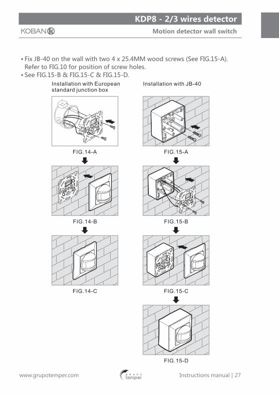
• Fix JB-40 on the wall with two 4 x 25.4MM wood screws (See FIG.15-A). Refer to FIG.10 for position of screw holes.
• See FIG.15-B & FIG.15-C & FIG.15-D.

28Instructions manual | www.grupotemper.com
KDP8 - 2/3 wires detectorMotion detector wall switch
Dismantle the plastic frameTo dismantle a fixed KDP8, please put the head of screwdriver at the nick of frame, then prize up the frame. To remove a flush mounted or surface mounted on junction box (JB-40) of KDP8, please refer to FIG.16-A & FIG.16-B respectively.
OperationKnob settingMETER、TIME、LUX knob (See FIG.17).Note:Make sure the slide switch is on the position of AUTO while adjusting the knob, otherwise, the settings on METER, TIME and LUX knob are disabled.

29Instructions manual | www.grupotemper.com
KDP8 - 2/3 wires detectorMotion detector wall switch
METER knob setting• Set Meter knob value at the position of "-", the smallest"field of view" will
be performed.• Set Meter knob value at the position of "+", the largest"field of view" will
be performed.• To adjust the Meter knob according to user's desire in between the position
of "+" & "-".TIME knob setting• Set Meter knob value at the position of "-", the smallest"field of view" will
be performed.• Set Meter knob value at the position of "+", the largest "field of view" will
be performed.• To adjust the Meter knob according to user's desire in between the position
of "+" & " ".• Set TIME knob value at the position of "-", the minimum delay time will be
6sec.• Set TIME knob value at the position of " + ", the maximum delay time will
be 12min.• To adjust the TIME knob according to user's desire in between the position
of "+" & "-".LUX knob setting• Set LUX knob value at the position of " ", the minimum LUX value will be
5LUX. KDP8 has no reaction against the movement as the actual light level is higher than 5LUX.
• Set LUX knob value at the position of " ", the maximum LUX value will be performed, in such way KDP8 responds to the movement at any light level.
• To adjust LUX knob according to user's desire in between the position of "" & " ".
Walk testThe purpose of the walk test is to select a proper installation place to get the best detection range. Set the slide switch at the position of AUTO, turn METER knob to "+", TIME knob to"-", LUX knob to " ", then conducting a walk test referring to sectionTest procedure and LUX is disable (See FIG.18).

30Instructions manual | www.grupotemper.com
KDP8 - 2/3 wires detectorMotion detector wall switch
Test procedure• Switch the power on.• Walk from outside across to the detection pattern,
once the detector is triggered, LED and load will all turn on for 6sec.
• Adjust METER knob to reach desired coverage.• Adjust TIME knob to change the switch off delay
time.• Refer to point " Usage of lens shield label", detection
range and angle can be changed by adjusting lens shield label.• Repeat this steps until it meets user's demands.• Pay attention to the walking direction while proceeding the test (See FIG.5).
Manual switch functionAUTO : Set slide switch in the middle, detector is in AUTO mode.OFF : Push the slide switch leftward, "O" icon appears at right, detector is in OFF mode, the connected lighting keeps permanent OFF.ON : Push the slide switch rightward, "I" icon appears at left, ON mode is activated, the connected lighting keeps permanent ON (See FIG.19).

31Instructions manual | www.grupotemper.com
KDP8 - 2/3 wires detectorMotion detector wall switch
Note: Do not take off the slide switch (See FIG.20).
Usage of lens shield labelThe attached lens shield label is used to reduce the detection range. With the different numbers of labels used, the different coverage can be obtained (See FIG.21).

32Instructions manual | www.grupotemper.com
KDP8 - 2/3 wires detectorMotion detector wall switch
TroubleshootingWhen KPD1 works abnormaly, please check assumptive problems and suggested solutions in following table that will hopefully to solve your problem.
Problem Possible cause Suggested solution
Load does not turn on
1.Wiring is connectedincorrectly.2.Malfunctioned load.3.Meter setting is too short.4.The slide switch is at OFF.
1. Please check whether the power supply and load are connected correctly or not.2.Replace the malfunctioned load with a new one.3.Setting METER at "+".4.Adjust slide switch at AUTO or ON.
Load does not turn off
1.TIME setting is too long,detector is continuouslytriggered.2.Detector is nuisance triggering.3.Wiring is connected incorrectly.
1.Setting TIME at "-" .2.Keep away from detection zone to avoid activating detector while doing the test.3.Please check whether the power is supplied and load is connected correctly or not.
Push buttondoes not work.
1. Incorrect time setting2.Detector is nuisance triggered.3. Wired incorrectly.
1.Please check if the push button is connected between T and L.2.Replace the push button with a new one.
Nuisancetriggering
There are heat sources, highly reflective objects orany objects which may be swayed in the wind within the detection coverage.
Avoid aiming the detector toward any heat sources, such as air conditioners,electric fans, heaters or any highly reflective surfaces. Make sure there are no swaying objects within thedetection coverage.

33Instructions manual | www.grupotemper.com
KDP8 - 2/3 wires detectorMotion detector wall switch
Note:Do not attempt to open or repair the unit without qualified electrician while it is malfunctioned.The following conditions may cause lower sensitivity:• In very foggy nights, the sensitivity may be less due to moisture collecting
on the lens.• In very hot days, the sensitivity may be less since high ambient temperature
is close to body temperature• In very cold days when heavy clothing is dressed, especially the facial area
is covered, very little heat will be emitted from the body causing the unit to be less sensitivity.
• Cleaning wipe with dry cloth only. Soap or rough cloth may damage the detector lens.
Shielding LabelThis label provides to cover the lens that would reduce detection range.

34Instructions manual | www.grupotemper.com
KDP8 - 2/3 wires detectorMotion detector wall switch
35Instructions manual | www.grupotemper.com
KDP8 - 2/3 wires detectorMotion detector wall switch
36Instructions manual | www.grupotemper.com
KDP8 - 2/3 wires detectorMotion detector wall switch

37Instructions manual | www.grupotemper.com
KDP8 - 2/3 wires detectorMotion detector wall switch

38Instructions manual | www.grupotemper.com
KDP8 - 2/3 wires detectorMotion detector wall switch

39Instructions manual | www.grupotemper.com
KDP8 - 2/3 wires detectorMotion detector wall switch

TEMPER ENERGY INTERNATIONAL S.L.Polígono industrial de Granda, nave 1833199 • Granda - Siero • Asturias
Teléfono: (+34) 902 201 292Fax: (+34) 902 201 303Email: [email protected]
Una empresadel grupo

TEMPER ENERGY INTERNATIONAL S.L. garantiza este aparato por 2 años ante todo defecto de fabricación. Para hacer válida esta garantía, es imprescindible presentar con este resguardo el ticket o factura de compra.
TEMPER ENERGY INTERNATIONAL S.L. guarantees this device during 2 years against any manufacturing defect. For warranty service, you must present this receipt with the purchase receipt or invoice.
TEMPER ENERGY INTERNATIONAL S.L. garantit cet apareil pour le durée de 2 annèes contre tout défault de fabrication. Pour le service de garantie, vous devez présenter ce reçu avec du ticket de caisse ou la facture.
TEMPER ENERGY INTERNATIONAL S.L. garantía este aparelho contra defeitos de fábrica ate 2 anos. Para o serviço de garantia, você deve apresentar este recibo com o recibo de compra ou fatura.
GARANTÍA • WARRANTYGARANTIE • GARANTIA 2años
yearsannéesanos
Ref. Art. Nº serie / Serial number
Nombre / Name / Nom / Nombre
Fecha de venta / Date of purchaseDate de vente / Data de venda
Sello establecimiento vendedor / Dealer stampCachet du commercant / Cambo da firma