detailed design of a search and rescue robot
TRANSCRIPT

Faculty of Engineering
Detailed Design of a Search and Rescue Robot
MTE 380
Prepared by
Group 3
Blair Chau 20458097
Ryan Chung 20469461
Jasdeep Dhillon 20468850
Jeremiah Soedirgo 20474411
Anthony Tenggoro 20454507
Tianyu Zeng 20460203
3B Mechatronics Engineering
February 29, 2016

February 29, 2016
Prof. Bill Owen
Associate Director of First-Year Engineering
Department of Mechanical and Mechatronics Engineering
University of Waterloo
Waterloo, Ontario
N2L 3G1
Dear Prof. Owen,
This report, entitled “Detailed Design of a Search and Rescue Robot” was prepared as Group 3’s
detailed design report for the MTE 380 search and rescue project. The purpose of this report is to
describe the specific designs decisions made to accomplish our initially proposed design.
We would like to acknowledge your assistance in defining and clarifying the objectives of the
project, and clearing up confusion regarding the reporting structure and content.
We are the sole authors of this report and, unless otherwise stated and properly referenced in the
report, the entire content of this report is original work done by us. We have all read the report
and are aware of the content. The content of this report has not received credit in this or any
other course that we have taken in the past or are currently taking at this time.
Sincerely Yours,
Group 3
Blair Chau Ryan Chung Jasdeep Dhillon
Jeremiah Soedirgo Anthony Tenggoro Tianyu Zeng

i
Executive Summary
Humans are now able to immigrate from Earth to Mars due to large technological advancements.
However, due to a collision on Mars from one of these trips, human beings sent from Earth to
Mars as settlers are stranded and in need of food and water supplies in order to survive. Because
of the danger posed, a rescue mission can only be conducted by way of an autonomous vehicle.
The vehicle must be able to go over a mountain range and deliver supplies to the base the
stranded humans have temporarily set up.
The initial, agreed upon objectives, constraints, and design selection criteria are reiterated from
the conceptual design phase. The design selection criteria against which the design alternatives
are compared against are weight, cost, travel time, construction time and number of human
interventions possibly required. An initial budget of $215 was set for the project, although after
actual component procurement, total costs have gone $93 over budget.
A work breakdown structure is presented in this report with timelines for important deadlines
and milestones. As per the planned schedule, a detailed design has been finalized including all
electronics and software design.
The previously selected general design involves traveling up a ramp on the edge of the mountain
range. Detailed mechanical design includes selection of a purchased enclosure and paired 60 mm
and 80 mm diameter wheels for ramp guidance. Detailed electrical design includes selection of a
stepper motor, an Arduino motor shield for control, ultrasonic sensors for distance measurement,
an inertial measurement unit for ramp detection and a 12 V battery for power supply. Detailed
control system design includes selection of a boundary offset algorithm for distance detection, a
tilt detection algorithm for ramp guidance, and a reference distance data algorithm to detect the
base to be found.
Testing involving the individual components should be performed as a next step, followed by
unified functionality testing as well as detailed sensor testing to obtain relevant metrics including
hold time, range and resolution.
ii
Table of Contents
Executive Summary ....................................................................................................................... i
List of Figures ................................................................................................................................ v
List of Tables ................................................................................................................................ vi
1 Introduction and Background .................................................................................................. 1
1.1 General Background ............................................................................................................. 1
1.2 Needs Assessment ................................................................................................................. 1
1.3 Problem Formulation ............................................................................................................ 1
1.3.1 Problem Definition......................................................................................................... 2
1.3.2 Desired Functions and Goals ......................................................................................... 2
1.3.3 Design Constraints ......................................................................................................... 2
1.3.4 Design Objectives .......................................................................................................... 3
1.3.5 Design Selection Criteria ............................................................................................... 3
1.3.6 Key Design Problems .................................................................................................... 3
2 Project Management .................................................................................................................. 5
2.1 Schedule ................................................................................................................................ 5
2.2 Deliverables .......................................................................................................................... 7
2.3 Budget ................................................................................................................................... 7
3 Detailed Design ........................................................................................................................... 9
3.1 Mechanical Design................................................................................................................ 9
3.1.1 Ramp Guiding Mechanism ............................................................................................ 9
3.1.1.1 Theory of Operation of Ramp Guiding Mechanism Alternatives .......................... 9
3.1.2 Evaluation of Ramp Guiding Mechanism.................................................................... 10
3.1.3 Enclosure and Wheel Selection ................................................................................... 10
3.1.3.1 Enclosure............................................................................................................... 10
3.1.3.2 Wheels................................................................................................................... 11
3.1.4 Torque .......................................................................................................................... 12
3.1.4.1 Explanation of Theory .......................................................................................... 12
3.1.4.2 Torque Specification for Motor Selection ............................................................ 13

iii
3.2 Electrical Design ................................................................................................................. 14
3.2.1 Drive Mechanism ......................................................................................................... 14
3.2.1.1 Motor Selection ..................................................................................................... 14
3.2.1.1.1 Defining Motor Specifications ....................................................................... 15
3.2.1.1.2 Theory of Operation of the Different Motor Alternatives ............................. 15
3.2.1.1.3 Evaluating Specific Motor Selection ............................................................. 16
3.2.1.2 Motor Controller Selection ................................................................................... 18
3.2.1.2.1 Explanation of Theory ................................................................................... 18
3.2.1.2.2 Evaluating Alternatives .................................................................................. 20
3.2.2 Sensor Selection ........................................................................................................... 21
3.2.2.1 Distance Sensing ................................................................................................... 21
3.2.2.1.1 Theory of Operation ....................................................................................... 22
3.2.2.1.2 Evaluating Alternatives .................................................................................. 22
3.2.2.2 Ramp Sensing ....................................................................................................... 23
3.2.3 Power ........................................................................................................................... 24
3.2.3.1 Explanation of Theory .......................................................................................... 24
3.2.3.2 Power Requirements ............................................................................................. 24
3.3 Control System Design ....................................................................................................... 28
3.3.1 Overview of System Functional Tasks ........................................................................ 29
3.3.2 Distance Sensing Algorithm ........................................................................................ 30
3.3.2.1 Sweeping Algorithm ............................................................................................. 30
3.3.2.2 Boundary Offset Algorithm .................................................................................. 31
3.3.2.3 Distance Sensing Algorithm Evaluation ............................................................... 33
3.3.3 Ramp Securing Algorithm ........................................................................................... 33
3.3.3.1 Tilt Detection Algorithm....................................................................................... 34
3.3.3.2 Motor Current Monitoring Algorithm .................................................................. 34
3.3.3.3 Ramp Securing Algorithm Evaluation .................................................................. 34
3.3.4 Destination Base Detection Algorithm ........................................................................ 34
3.3.4.1 Reference Distance Data Comparison Algorithm ................................................. 35
3.3.4.2 Extended Arm Deflection Sensing Algorithm ...................................................... 35
3.3.4.3 Destination Base Detection Algorithm Evaluation ............................................... 36

iv
3.4 Testing................................................................................................................................. 37
3.5 Summary of Final Design ................................................................................................... 37
3.5.1 Expected Performance ................................................................................................. 39
4 Conclusions and Recommendations ....................................................................................... 41
5 References ................................................................................................................................. 42
Appendix A – Static Coefficient of Friction Verification ........................................................ 44
Appendix B – CAD Drawings .................................................................................................... 45

v
List of Figures
Figure 1: Gantt Chart ...................................................................................................................... 6
Figure 2: Ramp Guidance Mechanism Alternatives ....................................................................... 9
Figure 3: Wheel configuration on flat part of ramp ...................................................................... 11
Figure 4: Free body diagram of the robot on the ramp ................................................................. 12
Figure 5: Torque-mass requirements for motor selection ............................................................. 14
Figure 6: Power Supply of the Arduino Mega R3 ........................................................................ 19
Figure 7: H-Bridge Example [6] ................................................................................................... 19
Figure 8: 30 Degree Detection Angle for the Ultrasonic Sensor (HC-SR04) [9] ......................... 22
Figure 9: Drawing 3263.9 mA of Current from a 9.1V to 12V Boost Converter ......................... 25
Figure 10: Drawing 3263.9 mA of Current from a 9V to 12V Boost Converter .......................... 25
Figure 11: Schematic of 9.6V Battery and Boost Converter System ........................................... 27
Figure 12: 12V Voltage Supply .................................................................................................... 27
Figure 13: 12V Battery Voltage Level under Full Load ............................................................... 28
Figure 14: 9.6V Battery and Boost Converter Voltage Level under Full Load ............................ 28
Figure 15: 12V Battery Current Level under Full Load ............................................................... 28
Figure 16: 9.6V Battery and Boost Converter Current Level under Full Load ............................ 28
Figure 17: Functional Task Flow Chart ........................................................................................ 29
Figure 18: Sweeping Algorithm Diagram..................................................................................... 31
Figure 19: Boundary Offset Algorithm Diagram.......................................................................... 32
Figure 20: Extended Arm Sensor .................................................................................................. 36
Figure 21: Final Design Exploded View ...................................................................................... 38
Figure 22: Complete Trajectory of the Robot ............................................................................... 40
Figure 23: Test setup for finding the coefficient of static friction ................................................ 44
Figure 24: Bottom Enclosure ........................................................................................................ 46
Figure 25: Battery Holder ............................................................................................................. 47
Figure 26: Enclosure Lid .............................................................................................................. 48
Figure 27: Enclosure ..................................................................................................................... 49

vi
List of Tables
Table 1: Budget Breakdown ........................................................................................................... 8
Table 2: Motor Criteria and Constraints ....................................................................................... 15
Table 3: Motor Decision Matrix ................................................................................................... 17
Table 4: Important Data Sheet Parameter of Soyo Stepper Motor ............................................... 18
Table 5: Motor Controller Constraints .......................................................................................... 20
Table 6: Comparing Adafruit Motor Shield Specifications With Design Constraint ................... 21
Table 7: IR vs Ultrasonic Sensor .................................................................................................. 23
Table 8: Electric Properties of the MPU6050 ............................................................................... 24
Table 9: Current Draw of Robot Components .............................................................................. 25
Table 10: Comparison between 12V Battery and 9.6V battery Boost Converter System ............ 26
Table 11: Major Parts Bill of Materials ........................................................................................ 39

1
1 Introduction and Background
This section provides an introduction to the design problem of interest, and outlines in more
detail the solution requirements by exploring the nature of this problem.
1.1 General Background
It is the year 2048. Advancements in technology have propelled humanity’s progress as a society
faster and further than it has ever been. Earth has finally united as a planet and humanity’s
brightest have gathered under a single banner to tackle the issue of a millennium; terraforming
and inhabiting Mars. An organization called Humanity’s Unified Bodily Relocation Initiative in
Space (HUBRIS) has been formed and its headquarters has been built on Mars right at the base
of the largest known mountain in the Solar System, Olympus Mons. With future expansion,
traveling, and tourism in mind, HUBRIS has constructed basic infrastructure in the form of a
road traversing the mountain and a monumental steel wall encasing the mountain. To help build
up the population, immigrants from Earth are periodically flown in on ships controlled from
Earth. In one of these trips, the ship encountered unexpected turbulence which could not be
avoided due to control latencies caused by the long distance between Earth and Mars, resulting in
an emergency landing on the other side of Olympus Mons. The harsh climate on Mars renders it
impossible for HUBRIS to develop a method to retrieve them before they die of starvation.
Instead, they devised a plan to create a smaller scale project to deliver supplies to the immigrants
in order to buy time to rescue them. As a result, project Destination Oriented Wireless
Navigation Fixed Autonomous Logical Locator (DOWNFALL) was born.
1.2 Needs Assessment
As it stands with their given food and water supply, the immigrants will not survive for more
than three months. In order to keep them alive, a method of traversing the mountain and
delivering these supplies to the temporary base must be devised before then.
1.3 Problem Formulation
The overall problem that must be addressed with a designed engineering solution is described in
this section. The problem is broken down and analyzed in terms of the functional goals of a
successful solution. These are then outlined as specific objectives and constraints for the design.
The design selection criteria are then derived from the design objectives.

2
1.3.1 Problem Definition
The general problem to be addressed is the following: a device must be designed and constructed
to be able to travel to the opposite side of a mountain range in order to conduct a search and
rescue mission.
1.3.2 Desired Functions and Goals
The functions necessary for a design to successfully address the design problem are listed below:
• The designed device should be able to travel from a starting location on one side of the
mountain range to a destination located on the opposite side.
• The device should be able to detect and climb on top of the base at the destination to
deliver supplies.
Listed below are goals which pertain to equipment availability and physical limitations:
• The device should remain within specified boundaries of the mountain range area at all
times while it is operating.
• The device should initially be under a specified size that allows for manual
transportation.
• The device should be controlled by a single specified microcontroller.
Additionally, there are goals correlated to the performance and optimization of a design, which
are listed below:
• The time required for the device to travel from its starting location to the destination
should be as low as possible.
• The device should have minimal mass.
• The device should accomplish its required tasks autonomously.
• The time required to design and construct the device should be as low as possible.
• The device should have minimal cost.
1.3.3 Design Constraints
The design constraints are derived from the concrete project requirements and the functions and
goals that are absolutely necessary to solving the design problem. At a bare minimum, the design
must carry out the search and rescue task, use the available microcontroller and have a
sufficiently small starting size. These constraints are quantified below:

3
• The device must be able to locate and travel to a destination of variable location on the
opposite side of the 0.9 m high mountain range.
• The device must be controlled solely by an ATMega2560 microcontroller.
• The device must remain within the 2.4 m by 4.8 m site while performing its required
tasks.
• The dimensions of the device must be within 0.6 m by 0.6 m by 0.6 m prior to being
activated.
1.3.4 Design Objectives
The design objectives are selected by expanding the goals for the design which will influence the
performance or engineering costs. The performance index depends upon both the device mass
and the search and rescue time. Search and rescue time is in turn influenced by the number of
times a human intervention/troubleshooting becomes necessary. Engineering costs are broken
down into financial costs and required engineering effort for design and construction. These
objectives are quantified below:
• The device should travel from Base 1 to Base 2 in under 60 s.
• The device should have a mass under 5 kg.
• The device should require 0 instances of human intervention during operation.
• Total design/construction time for the device should be under 500 h.
• The total cost for designing and constructing the device should be less than $215 (CAD).
1.3.5 Design Selection Criteria
The design selection criteria used to compare several viable design alternatives are derived from
the design objectives listed above. These criteria are shown below:
• Mass(kg)
• Cost (CAD)
• Travel time (s)
• Construction time (h)
• Human Intervention Instances (#)
1.3.6 Key Design Problems
The search and rescue tasks can be broken down into the following smaller design problems:

4
• The device requires a method of transportation/movement that can be controlled or
predetermined.
• The device requires a method of travelling across the mountain range.
• The device requires a method of determining the location of the destination base.
• The device requires a method of determining its own location relative to the base, the
area boundaries, the mountain range and the ramp over the range.
The second design problem is specifically focused on travelling over the mountain range, as
travelling around the range is not permissible. The options of tunneling under or through the
range are rejected due to the safety concerns that would be raised by the methods of doing so,
along with the unreasonably high costs of acquiring the necessary equipment.
Taken together, these smaller tasks are the essential, minimum requirements that any viable
design must be able to accomplish. The specifics of using location to adjust or control the
movement of the device are discussed in the detailed design sections of this report.

5
2 Project Management
The following section outlines the project management details of the project. This section
provides information regarding the members of the team, the work breakdown, task distribution,
risk mitigation, and the budget. This information paves the path and direction the team will
follow for the rest of the project.
2.1 Schedule
The project schedule is displayed below in Figure 1 as a Gantt chart. Within the Gantt chart, the
milestones are highlighted in green with the subtasks in white. As the subtasks are completed,
the completion of the milestone approaches more towards 100 percent. This is represented by the
progress bar which provide a visual indication of the project completion. For milestones, the
expected duration of work for the milestone is shown in light blue. As progress is made towards
the completion of the milestone, the light blue bar is filled by the darker blue bar. For subtasks,
the indications are similar with the use of light green and dark green instead. Figure 1 below
shows the Gantt Chart for this project which indicate the start and end date of the task as well as
the owner of the specific task.

6
Figure 1: Gantt Chart
ProjectDOWNFALL StartDate January8,2016
HUBRIS TotalDuration 63
Task StartDate EndDate
Duration
(Days) PercentComplete Owners(s) DetailedDescription 08 09 10 11 12 13 14 15 16 17 18 19 20 21 22 23 24 25 26 27 28 29 30 31 01 02 03 04 05 06 07 08 09 10 11 12 13 14 15 16 17 18 19 20 21 22 23 24 25 26 27 28 29 01 02 03 04 05 06 07 08 09 10
1.0Milestone1 2016-01-08 2016-01-22 15 100.00% 2 2 2 2 2 2 2 2 2 2 2 2 2 2 2 0 0 0 0 0 0 0 0 0 0 0 0 0 0 0 0 0 0 0 0 0 0 0 0 0 0 0 0 0 0 0 0 0 0 0 0 0 0 0 0 0 0 0 0 0 0 0 0
1.1Proposal 2016-01-08 2016-01-22 15 100.00% Ryan ConstructionCheck#1 2 2 2 2 2 2 2 2 2 2 2 2 2 2 2 0 0 0 0 0 0 0 0 0 0 0 0 0 0 0 0 0 0 0 0 0 0 0 0 0 0 0 0 0 0 0 0 0 0 0 0 0 0 0 0 0 0 0 0 0 0 0 0
2.0Milestone2 2016-01-25 2016-02-05 12 100.00% 0 0 0 0 0 0 0 0 0 0 0 0 0 0 0 0 0 2 2 2 2 2 2 2 2 2 2 2 2 0 0 0 0 0 0 0 0 0 0 0 0 0 0 0 0 0 0 0 0 0 0 0 0 0 0 0 0 0 0 0 0 0 0
2.1SensorSelection 2016-01-25 2016-01-27 3 100.00% Tian,Anthony Kinematics,torque,stress,etccalcuations. 0 0 0 0 0 0 0 0 0 0 0 0 0 0 0 0 0 2 2 2 0 0 0 0 0 0 0 0 0 0 0 0 0 0 0 0 0 0 0 0 0 0 0 0 0 0 0 0 0 0 0 0 0 0 0 0 0 0 0 0 0 0 0
2.2MechanicalCalculations 2016-01-25 2016-01-27 3 100.00% Jeremiah,Blair Includesmotors,sensors,power 0 0 0 0 0 0 0 0 0 0 0 0 0 0 0 0 0 2 2 2 0 0 0 0 0 0 0 0 0 0 0 0 0 0 0 0 0 0 0 0 0 0 0 0 0 0 0 0 0 0 0 0 0 0 0 0 0 0 0 0 0 0 0
2.3PartSelection 2016-01-25 2016-01-27 3 100.00% Anthony,Tian DesigndoneinCAD. 0 0 0 0 0 0 0 0 0 0 0 0 0 0 0 0 0 2 2 2 0 0 0 0 0 0 0 0 0 0 0 0 0 0 0 0 0 0 0 0 0 0 0 0 0 0 0 0 0 0 0 0 0 0 0 0 0 0 0 0 0 0 0
2.4ChassisDesign 2016-01-28 2016-01-29 2 100.00% Jeremiah,Blair Groupmeeting. 0 0 0 0 0 0 0 0 0 0 0 0 0 0 0 0 0 0 0 0 2 2 0 0 0 0 0 0 0 0 0 0 0 0 0 0 0 0 0 0 0 0 0 0 0 0 0 0 0 0 0 0 0 0 0 0 0 0 0 0 0 0 0
2.5MechanicalDesignReviewMeeting 2016-01-29 2016-01-29 1 100.00% Ryan,Jeremiah Purchasemotors,sensors,andothermajor 0 0 0 0 0 0 0 0 0 0 0 0 0 0 0 0 0 0 0 0 0 2 0 0 0 0 0 0 0 0 0 0 0 0 0 0 0 0 0 0 0 0 0 0 0 0 0 0 0 0 0 0 0 0 0 0 0 0 0 0 0 0 0
2.6PurchaseComponents 2016-01-29 2016-02-01 4 100.00% Anthony Twobuisnessdaysoutoffourtotaldays. 0 0 0 0 0 0 0 0 0 0 0 0 0 0 0 0 0 0 0 0 0 2 2 2 2 0 0 0 0 0 0 0 0 0 0 0 0 0 0 0 0 0 0 0 0 0 0 0 0 0 0 0 0 0 0 0 0 0 0 0 0 0 0
2.7Machining 2016-01-29 2016-02-01 4 100.00% Anthony,Jasdeep 0 0 0 0 0 0 0 0 0 0 0 0 0 0 0 0 0 0 0 0 0 2 2 2 2 0 0 0 0 0 0 0 0 0 0 0 0 0 0 0 0 0 0 0 0 0 0 0 0 0 0 0 0 0 0 0 0 0 0 0 0 0 0
2.8MechanicalAssembly 2016-02-02 2016-02-03 2 100.00% Jasdeep,Ryan 0 0 0 0 0 0 0 0 0 0 0 0 0 0 0 0 0 0 0 0 0 0 0 0 0 2 2 0 0 0 0 0 0 0 0 0 0 0 0 0 0 0 0 0 0 0 0 0 0 0 0 0 0 0 0 0 0 0 0 0 0 0 0
2.9Milestone1Buffer 2016-02-04 2016-02-05 2 100.00% All DetailedDesignReport 0 0 0 0 0 0 0 0 0 0 0 0 0 0 0 0 0 0 0 0 0 0 0 0 0 0 0 2 2 0 0 0 0 0 0 0 0 0 0 0 0 0 0 0 0 0 0 0 0 0 0 0 0 0 0 0 0 0 0 0 0 0 0
3.0Milestone3 2016-02-08 2016-02-26 19 87.50% DesigndoneinCAD. 0 0 0 0 0 0 0 0 0 0 0 0 0 0 0 0 0 0 0 0 0 0 0 0 0 0 0 0 0 0 0 2 2 2 2 2 2 2 2 2 2 2 2 2 2 2 2 2 1 1 0 0 0 0 0 0 0 0 0 0 0 0 0
3.1HousingDesign 2016-02-08 2016-02-10 3 100.00% Jeremiah,Jasdeep 0 0 0 0 0 0 0 0 0 0 0 0 0 0 0 0 0 0 0 0 0 0 0 0 0 0 0 0 0 0 0 2 2 2 0 0 0 0 0 0 0 0 0 0 0 0 0 0 0 0 0 0 0 0 0 0 0 0 0 0 0 0 0
3.2SensorSignalConditioningCircuitDesign 2016-02-08 2016-02-09 2 100.00% Tian,Anthony 0 0 0 0 0 0 0 0 0 0 0 0 0 0 0 0 0 0 0 0 0 0 0 0 0 0 0 0 0 0 0 2 2 0 0 0 0 0 0 0 0 0 0 0 0 0 0 0 0 0 0 0 0 0 0 0 0 0 0 0 0 0 0
3.3MotorControlCircuitDesign 2016-02-10 2016-02-11 2 100.00% Anthony,Tian Sensorsandactuatorlayoutandpin 0 0 0 0 0 0 0 0 0 0 0 0 0 0 0 0 0 0 0 0 0 0 0 0 0 0 0 0 0 0 0 0 0 2 2 0 0 0 0 0 0 0 0 0 0 0 0 0 0 0 0 0 0 0 0 0 0 0 0 0 0 0 0
3.4PeripheralManagement 2016-02-12 2016-02-12 1 100.00% Tian,Jasdeep 0 0 0 0 0 0 0 0 0 0 0 0 0 0 0 0 0 0 0 0 0 0 0 0 0 0 0 0 0 0 0 0 0 0 0 2 0 0 0 0 0 0 0 0 0 0 0 0 0 0 0 0 0 0 0 0 0 0 0 0 0 0 0
3.5ElectricalDesignReviewMeeting 2016-02-13 2016-02-13 1 100.00% Tian,Ryan 0 0 0 0 0 0 0 0 0 0 0 0 0 0 0 0 0 0 0 0 0 0 0 0 0 0 0 0 0 0 0 0 0 0 0 0 2 0 0 0 0 0 0 0 0 0 0 0 0 0 0 0 0 0 0 0 0 0 0 0 0 0 0
3.6FiniteStateMachineDesign 2016-02-08 2016-02-09 2 100.00% Ryan,Blair Researchanddevelopsearchalgorithm. 0 0 0 0 0 0 0 0 0 0 0 0 0 0 0 0 0 0 0 0 0 0 0 0 0 0 0 0 0 0 0 2 2 0 0 0 0 0 0 0 0 0 0 0 0 0 0 0 0 0 0 0 0 0 0 0 0 0 0 0 0 0 0
3.7SearchAlgorithmEvaluation/Design 2016-02-10 2016-02-11 2 100.00% Blair Modelmotorstogenerateitsresponses. 0 0 0 0 0 0 0 0 0 0 0 0 0 0 0 0 0 0 0 0 0 0 0 0 0 0 0 0 0 0 0 0 0 2 2 0 0 0 0 0 0 0 0 0 0 0 0 0 0 0 0 0 0 0 0 0 0 0 0 0 0 0 0
3.8MotorControlsDriverandAPIDesign 2016-02-10 2016-02-11 2 100.00% Ryan,Jeremiah Typicalmovementtherobotwilltake. 0 0 0 0 0 0 0 0 0 0 0 0 0 0 0 0 0 0 0 0 0 0 0 0 0 0 0 0 0 0 0 0 0 2 2 0 0 0 0 0 0 0 0 0 0 0 0 0 0 0 0 0 0 0 0 0 0 0 0 0 0 0 0
3.9MovementControlsDriverandAPIDesign 2016-02-12 2016-02-13 2 0.00% Ryan,Jeremiah 0 0 0 0 0 0 0 0 0 0 0 0 0 0 0 0 0 0 0 0 0 0 0 0 0 0 0 0 0 0 0 0 0 0 0 1 1 0 0 0 0 0 0 0 0 0 0 0 0 0 0 0 0 0 0 0 0 0 0 0 0 0 0
3.10SensorSignalProcessingAlgorithmandAPIDesign 2016-02-12 2016-02-13 2 0.00% Blair Plansfortestingthesearchalgorithm. 0 0 0 0 0 0 0 0 0 0 0 0 0 0 0 0 0 0 0 0 0 0 0 0 0 0 0 0 0 0 0 0 0 0 0 1 1 0 0 0 0 0 0 0 0 0 0 0 0 0 0 0 0 0 0 0 0 0 0 0 0 0 0
3.11SearchAlgorithmTestPlan 2016-02-14 2016-02-16 3 100.00% Jasdeep,Blair 0 0 0 0 0 0 0 0 0 0 0 0 0 0 0 0 0 0 0 0 0 0 0 0 0 0 0 0 0 0 0 0 0 0 0 0 0 2 2 2 0 0 0 0 0 0 0 0 0 0 0 0 0 0 0 0 0 0 0 0 0 0 0
3.12SoftwareDesignReviewMeeting 2016-02-17 2016-02-17 1 100.00% Blair,Ryan 0 0 0 0 0 0 0 0 0 0 0 0 0 0 0 0 0 0 0 0 0 0 0 0 0 0 0 0 0 0 0 0 0 0 0 0 0 0 0 0 2 0 0 0 0 0 0 0 0 0 0 0 0 0 0 0 0 0 0 0 0 0 0
3.13DetailedDesignReport 2016-02-18 2016-02-21 4 100.00% Ryan 0 0 0 0 0 0 0 0 0 0 0 0 0 0 0 0 0 0 0 0 0 0 0 0 0 0 0 0 0 0 0 0 0 0 0 0 0 0 0 0 0 2 2 2 2 0 0 0 0 0 0 0 0 0 0 0 0 0 0 0 0 0 0
3.14Milestone3Buffer 2016-02-22 2016-02-26 5 100.00% All ConstructionCheck#2 0 0 0 0 0 0 0 0 0 0 0 0 0 0 0 0 0 0 0 0 0 0 0 0 0 0 0 0 0 0 0 0 0 0 0 0 0 0 0 0 0 0 0 0 0 2 2 2 2 2 0 0 0 0 0 0 0 0 0 0 0 0 0
4.0Milestone4 2016-02-27 2016-03-04 7 8.33% 0 0 0 0 0 0 0 0 0 0 0 0 0 0 0 0 0 0 0 0 0 0 0 0 0 0 0 0 0 0 0 0 0 0 0 0 0 0 0 0 0 0 0 0 0 0 0 0 0 0 2 1 1 1 1 1 1 0 0 0 0 0 0
4.1ElectricalAssembly 2016-02-27 2016-02-28 2 50.00% Anthony,Jasdeep 0 0 0 0 0 0 0 0 0 0 0 0 0 0 0 0 0 0 0 0 0 0 0 0 0 0 0 0 0 0 0 0 0 0 0 0 0 0 0 0 0 0 0 0 0 0 0 0 0 0 2 1 0 0 0 0 0 0 0 0 0 0 0
4.3HardwareVerification 2016-02-28 2016-02-29 2 0.00% Jasdeep Integratealldrivers,fsm,andalgorithms. 0 0 0 0 0 0 0 0 0 0 0 0 0 0 0 0 0 0 0 0 0 0 0 0 0 0 0 0 0 0 0 0 0 0 0 0 0 0 0 0 0 0 0 0 0 0 0 0 0 0 0 1 1 0 0 0 0 0 0 0 0 0 0
4.4SoftwareImplementation 2016-02-27 2016-02-28 2 0.00% Blair,Ryan,Tian Ensuresthatthesoftwarebehaves 0 0 0 0 0 0 0 0 0 0 0 0 0 0 0 0 0 0 0 0 0 0 0 0 0 0 0 0 0 0 0 0 0 0 0 0 0 0 0 0 0 0 0 0 0 0 0 0 0 0 1 1 0 0 0 0 0 0 0 0 0 0 0
4.6SystemIntegration 2016-02-29 2016-03-02 3 0.00% Jasdeep,Jeremiah Fieldtest(Includesbufferformilestone4 0 0 0 0 0 0 0 0 0 0 0 0 0 0 0 0 0 0 0 0 0 0 0 0 0 0 0 0 0 0 0 0 0 0 0 0 0 0 0 0 0 0 0 0 0 0 0 0 0 0 0 0 1 1 1 0 0 0 0 0 0 0 0
4.7SystemLevelTesting 2016-03-02 2016-03-04 3 0.00% Jasdeep,Tian Presentation 0 0 0 0 0 0 0 0 0 0 0 0 0 0 0 0 0 0 0 0 0 0 0 0 0 0 0 0 0 0 0 0 0 0 0 0 0 0 0 0 0 0 0 0 0 0 0 0 0 0 0 0 0 0 1 1 1 0 0 0 0 0 0
5.0Milestone5 2016-02-29 2016-03-04 5 0.00% 0 0 0 0 0 0 0 0 0 0 0 0 0 0 0 0 0 0 0 0 0 0 0 0 0 0 0 0 0 0 0 0 0 0 0 0 0 0 0 0 0 0 0 0 0 0 0 0 0 0 0 0 1 1 1 1 1 0 0 0 0 0 0
5.1DesignPostMortemMeeting 2016-02-29 2016-02-29 1 0.00% Ryan Createpowerpointforpresentation. 0 0 0 0 0 0 0 0 0 0 0 0 0 0 0 0 0 0 0 0 0 0 0 0 0 0 0 0 0 0 0 0 0 0 0 0 0 0 0 0 0 0 0 0 0 0 0 0 0 0 0 0 1 0 0 0 0 0 0 0 0 0 0
5.2DesignPresentation 2016-03-01 2016-03-04 4 0.00% Ryan,Jeremiah Competition 0 0 0 0 0 0 0 0 0 0 0 0 0 0 0 0 0 0 0 0 0 0 0 0 0 0 0 0 0 0 0 0 0 0 0 0 0 0 0 0 0 0 0 0 0 0 0 0 0 0 0 0 0 1 1 1 1 0 0 0 0 0 0
6.0Milestone6 2016-03-07 2016-03-10 4 0.00% Additionalfieldteststoworkoutedge
cases.
0 0 0 0 0 0 0 0 0 0 0 0 0 0 0 0 0 0 0 0 0 0 0 0 0 0 0 0 0 0 0 0 0 0 0 0 0 0 0 0 0 0 0 0 0 0 0 0 0 0 0 0 0 0 0 0 0 0 0 1 1 1 1
6.1TestRuns 2016-03-07 2016-03-10 4 0.00% All 0 0 0 0 0 0 0 0 0 0 0 0 0 0 0 0 0 0 0 0 0 0 0 0 0 0 0 0 0 0 0 0 0 0 0 0 0 0 0 0 0 0 0 0 0 0 0 0 0 0 0 0 0 0 0 0 0 0 0 1 1 1 1
January February March

7
2.2 Deliverables
During the course of the project, there are several deliverables that must be completed. The
deliverables are listed below in order of completion:
• Report #1 (January 22, 2016) - Proposal and Conceptual Design: outlines a work plan for
the project that describes the activities and expectations of the team for the project.
Included in this report are details about the conceptual design and the decision making
process of the team that lead to the selected design.
• Construction Check 1 (February 5, 2016): completion of only the mechanical components
of the design, so the body and chassis of the robot.
• Report #2 - Detailed Design (February 29, 2016): The second report includes a detailed
design analysis of the design, material and part selection of the robot.
• Construction Check #2 (March 4, 2016): the vehicle is able to turn on and perform an
action, such as moving on its own.
• Presentation (March 4, 2016): present the design analysis
• Competition (March 18, 2016): vehicle will perform its search and rescue while
competing against other teams.
• Report #3 – Final (April 1, 2016): reflection of the final vehicle design in how it matches
up to the objectives and constraints. Also, a discussion of the results from the
competition.
2.3 Budget
In this section the budget is outlined to show how much money has been allocated for each
component that needs to be bought for the design and the total should be equal or less than $215.
The cost of labour is 0 because HUBRIS is a team made up of unpaid interns. The budget can be
seen in Table 1 below.

8
Table 1: Budget Breakdown
The budget requirement for the project has been updated to reflect certain issues that were not
considered in the initial report. The team had underestimated the torque requirement of the robot
and as such more expensive motors had to be purchased. Initially, the team was going to design
the enclosure, however to reduce costs, a general purpose enclosure was purchased instead for a
lower price. The budget for the wheels selected initially remain the same as the wheels do not
change. The budget for the battery and circuit elements have increased as the more powerful
motor requires a lot more current than initially predicted. Lastly, the estimate for extra parts
needed for the project also increased as extra parts were needed to assembly the unit to the
enclosure. This brings the total budget to $308 dollars which is $93 more than the $215 budget
initially provided.
Cost Estimate 1
($CAD)
Cost Estimate 2
($CAD)
Hardware Motor 22 85
Enclosure 75 10
Wheels 25 25
Sensors 20 28
Battery 10 20
Circuit elements 20 40
Emergency Extra parts 43 100
Labour Interns 0 0
Total $215 $308

9
3 Detailed Design
The previously selected general design was the solution involving using the ramp to travel over
the mountain range wall on wheels. The following sections document the more detailed design
decisions for the project. This is split into three components: mechanical, electrical, and controls.
3.1 Mechanical Design
This section provides the design reasoning for the mechanical design and the part selection. In
addition, a torque specification is required to give to the electrical engineering team as an aid in
motor selection.
3.1.1 Ramp Guiding Mechanism
One of the requirements for the design is that the robot must not fall off the ramp. While there
are methods to achieve this using sensors, the controls team expressed a desire for a mechanical
means of ensuring that the robot stays on the ramp. A mechanical mechanism for physical ramp
guidance prevents total dependence on sensors and software at little foreseeable additional cost.
3.1.1.1 Theory of Operation of Ramp Guiding Mechanism Alternatives
Two design alternatives for the ramp guidance mechanism are considered in this section: a
pivoting arm which clings onto the edge of the ramp, and a larger additional wheels that clamp
the robot onto the ramp. Sketches of the two alternatives are shown below in Figure 2.
Figure 2: Ramp Guidance Mechanism Alternatives
The first method considered for ramp guidance involves an arm on the right and left sides of the
robot that is in use only as the robot goes up the ramp. When the robot is on the ramp, a drive
mechanism is required to lower the arms to wrap onto the underside of the ramp.
The second method considered is to have a two-wheel configuration as shown to the right in
Figure 2 In this configuration, during normal operation on flat surfaces, the outer wheels are
used. When going up the ramp, the calibrated distance between the outer wheels on the right and

10
left sides prevents them from being used on the ramp. Thus the inner wheels are used, with the
outer wheels functioning as guides to ensure the robot goes straight up the ramp without falling.
3.1.2 Evaluation of Ramp Guiding Mechanism
Based on considerations of the design criteria of cost, construction time, and mass, it is
determined that the second method is the better option. With only four additional wheels, the
cost is likely lower than the first option where materials for the arm as well as the motor for
moving it are necessary. With the second option also being easier to implement, the construction
time is greatly reduced. Finally, while the material of the additional wheels plays a factor, the
second design will weigh less than the motor and arm mechanism.
3.1.3 Enclosure and Wheel Selection
With the general design of the robot’s appearance decided, this section shows the selection
process of an enclosure and wheels.
3.1.3.1 Enclosure
For the selection of an appropriate enclosure design, a decision is made between using a
prefabricated enclosure or a custom manufactured one. The problems with making an enclosure
include more time and money being spent. One of the goals for the project is that the time
required to design and construct the vehicle should be kept low as possible. In order to reduce the
risks in creating an enclosure, it is decided to use a store bought enclosure to ensure reliability,
reduce costs and keep construction time to a minimum.
Now the dimensions of the enclosure are to be chosen. The vehicle is uses a two-wheel
configuration on each axle, where the outer wheels clamp on the sides of the ramp. In order to
accomplish this, the enclosure needs a width that is less than 152 mm. Also, the minimum width
is 80 mm to ensure at least two motors can fit in the enclosure as each motor has a width of 40
mm. For the length and height of the enclosure, a conservative size is used, which is
approximately double the dimensions of the Arduino Mega 2560. The maximum length is 200
mm and minimum height is 30 mm. The minimum height has to be changed to ensure that any
motor chosen can fit. So a minimum height of 50 mm is chosen since motor heights are usually
around 40 mm and using a bigger height can ensure any size of motor can fit and other electronic
components can fit the enclosure. The minimum length that the enclosure has is 115 mm, to

11
ensure that enclosure can fit the Arduino which has a length of 101 mm and have a bit of space
between the parts in the enclosure. This ensures that there isn't a tight fit and it is easy to arrange
the parts in the enclosure. After the dimensions and materials of the enclosure are decided on, a
decision is made for where to buy the enclosure from. The decision is to use a local supplier that
carried enclosures, which saves money on shipping and have enclosure faster. The common
series at the supplier was the Hammond 1591 series enclosures and the enclosures didn't have
holes for the shafts of the motors, so the enclosure needed to be made of ABS plastic, so it is
easy to drill into and make modifications to enclosure if required later on. The biggest enclosure
at the local supplier that had the dimensions required is the Hammond 1591E enclosure. The
length, width and height of the enclosure used are 191 mm, 110 mm, and 57 mm.
3.1.3.2 Wheels
Based on the enclosure height of 57 mm and assuming that the axle of the motor is placed in the
center of the side of the enclosure, a wheel is required that has a radius that is least 28.5 mm.
This ensures that the enclosure isn't scraping against the floor. Looking at the plastic wheels with
rubber tires from a local supplier, Creatron, the smallest radius of wheel that is available are 60
mm diameter wheels.
The vehicle uses an inner and outer wheel configuration to stay balanced on the ramp, so a wheel
size is to be determined for the outer wheel. Looking at Figure 3 below where the vehicle is at
the flat part of the ramp, the maximum difference between the inner and outer wheel is equal to
the thickness of the wood, otherwise the outer wheels will get stuck by the mountain walls. The
maximum difference is then 19.05 mm and gives a maximum radius of 49.05 mm. The wheels
chosen for the outer wheel was selected to have a diameter of 80mm.
Figure 3: Wheel configuration on flat part of ramp
12
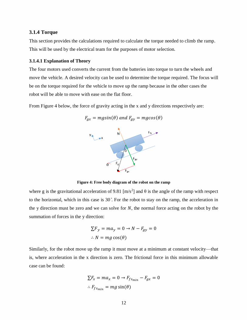
3.1.4 Torque
This section provides the calculations required to calculate the torque needed to climb the ramp.
This will be used by the electrical team for the purposes of motor selection.
3.1.4.1 Explanation of Theory
The four motors used converts the current from the batteries into torque to turn the wheels and
move the vehicle. A desired velocity can be used to determine the torque required. The focus will
be on the torque required for the vehicle to move up the ramp because in the other cases the
robot will be able to move with ease on the flat floor.
From Figure 4 below, the force of gravity acting in the x and y directions respectively are:
𝐹𝑔𝑥 = 𝑚𝑔𝑠𝑖𝑛(𝜃) 𝑎𝑛𝑑 𝐹𝑔𝑦 = 𝑚𝑔𝑐𝑜𝑠(𝜃)
Figure 4: Free body diagram of the robot on the ramp
where g is the gravitational acceleration of 9.81 [m/s2] and θ is the angle of the ramp with respect
to the horizontal, which in this case is 30 ̊. For the robot to stay on the ramp, the acceleration in
the y direction must be zero and we can solve for 𝑁, the normal force acting on the robot by the
summation of forces in the y direction:
∑𝐹𝑦 = 𝑚𝑎𝑦 = 0 → 𝑁 − 𝐹𝑔𝑦 = 0
∴ 𝑁 = 𝑚𝑔 cos(𝜃)
Similarly, for the robot move up the ramp it must move at a minimum at constant velocity—that
is, where acceleration in the x direction is zero. The frictional force in this minimum allowable
case can be found:
∑𝐹𝑥 = 𝑚𝑎𝑥 = 0 → 𝐹𝑓𝑠𝑚𝑖𝑛− 𝐹𝑔𝑥 = 0
∴ 𝐹𝑓𝑠𝑚𝑖𝑛= 𝑚𝑔 sin(𝜃)

13
The wheels utilize static friction in order to move the vehicle up the ramp. However, static
friction is only operational up to a certain maximum threshold of force before giving way to
kinetic friction. The maximum static friction 𝐹𝑓𝑠𝑚𝑎𝑥 is determined by the equation:
𝐹𝑓𝑠𝑚𝑎𝑥= 𝜇𝑠𝑁 → 𝐹𝑓𝑠𝑚𝑎𝑥
= 𝜇𝑠𝑚𝑔 cos(𝜃)
where 𝜇𝑠 is the coefficient of static friction between the wheel and the ramp. Therefore, the static
frictional force is constrained by a lower and upper bound in order for the robot to move up the
ramp successfully:
𝑚𝑔𝑠𝑖𝑛(𝜃) ≤ 𝐹𝑓𝑠 ≤ 𝜇𝑠𝑚𝑔𝑐𝑜𝑠(𝜃)
The frictional force on the wheels is 𝐹𝑓𝑠 , and the total torque of the motors is 𝑇. These two can
be related to the wheel radius 𝑅 by 𝐹𝑓𝑠 =𝑇
𝑅 . Substituting and rearranging the final expression is:
𝑔𝑅𝑠𝑖𝑛(𝜃) ≤𝑇
𝑚≤ 𝜇𝑠𝑔𝑅𝑐𝑜𝑠(𝜃)
3.1.4.2 Torque Specification for Motor Selection
For this specific design, the parameters that are known are the gravitational acceleration 9.81
m/s2, the tilt angle of the ramp 𝜃, the radius R of the inner wheel that will be in contact with the
ramp, and the coefficient of static friction 𝜇𝑠. While the tilt angle of the ramp is specified to be
30° and the radius of the selected inner wheel is 30 mm as outlined previously, the coefficient of
static friction was determined experimentally to be 0.878, using the test setup as detailed in
Appendix A.
The only unknown is the mass, because not all the selected components are known. However,
knowing the mass of the enclosure, wheel assembly, and Arduino, and estimating the mass of the
other components, it is estimated that the mass of components excluding the motors is 0.7 kg.
Separating the total mass 𝑚 into the mass of the motors 𝑚𝑚𝑜𝑡𝑜𝑟𝑠 and the mass of the other
components 𝑚𝑜𝑡ℎ𝑒𝑟 = 0.7 𝑘𝑔, and substituting all parameters into the inequality, the
requirement becomes:
0.14715 ≤𝑇
𝑚𝑚𝑜𝑡𝑜𝑟𝑠 + 0.7≤ 0.22378
Simplifying to reduce for the torque and mass of each individual motor out of the four total:

14
0.14715 ≤4𝑇𝑚𝑜𝑡𝑜𝑟
4𝑚𝑚𝑜𝑡𝑜𝑟 + 0.7≤ 0.22378
where mass is in kilograms and torque is in Newton-meters. A graphical representation of this
torque-mass requirement is shown below in Figure 5.
Figure 5: Torque-mass requirements for motor selection
Therefore, any motor with a mass and torque combination within the shaded region will be allow
the robot to travel up the ramp without slippage.
3.2 Electrical Design
This section provides the analysis and evaluation of electrical design decisions leading up to the
selection of parts used in the final design.
3.2.1 Drive Mechanism
This section provides the analysis and evaluation of electrical design decisions made in selecting
electrical parts needed for the drivetrain to allow for propulsion.
3.2.1.1 Motor Selection
This section will outline the motor selection process in accordance with the weight and torque
calculations specified in Section 3.1.4.2 above.
15
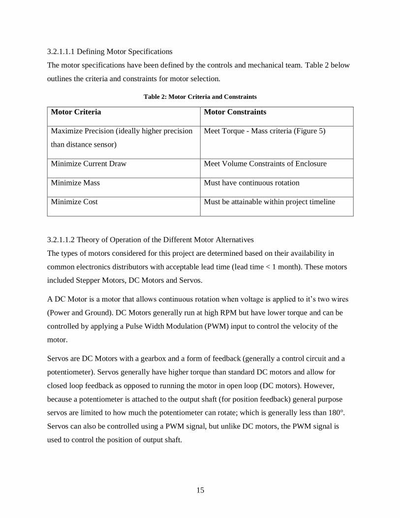
3.2.1.1.1 Defining Motor Specifications
The motor specifications have been defined by the controls and mechanical team. Table 2 below
outlines the criteria and constraints for motor selection.
Table 2: Motor Criteria and Constraints
Motor Criteria Motor Constraints
Maximize Precision (ideally higher precision
than distance sensor)
Meet Torque - Mass criteria (Figure 5)
Minimize Current Draw Meet Volume Constraints of Enclosure
Minimize Mass Must have continuous rotation
Minimize Cost Must be attainable within project timeline
3.2.1.1.2 Theory of Operation of the Different Motor Alternatives
The types of motors considered for this project are determined based on their availability in
common electronics distributors with acceptable lead time (lead time < 1 month). These motors
included Stepper Motors, DC Motors and Servos.
A DC Motor is a motor that allows continuous rotation when voltage is applied to it’s two wires
(Power and Ground). DC Motors generally run at high RPM but have lower torque and can be
controlled by applying a Pulse Width Modulation (PWM) input to control the velocity of the
motor.
Servos are DC Motors with a gearbox and a form of feedback (generally a control circuit and a
potentiometer). Servos generally have higher torque than standard DC motors and allow for
closed loop feedback as opposed to running the motor in open loop (DC motors). However,
because a potentiometer is attached to the output shaft (for position feedback) general purpose
servos are limited to how much the potentiometer can rotate; which is generally less than 180o.
Servos can also be controlled using a PWM signal, but unlike DC motors, the PWM signal is
used to control the position of output shaft.

16
While DC Motors and Servos, rely on energizing a single coil to allow for rotation, Stepper
motors have a system of coils/electromagnets around a central shaft that are energized in an
alternating pattern. Each phase in the pattern will align the central shaft to one of the coils, while
being slightly offset from the other coil. Controlling which coil is energized at a point in time
allows the shaft to rotate. Steppers require an external control circuit that will alternate the order
of energizing the coil in such a way that the shaft can be commanded to move to a specific
position (in other words commanded to go a certain number of steps). Stepper motors are not
limited to a degree of rotation, or in other words, like DC motors, they have the ability to rotate
continuously.
3.2.1.1.3 Evaluating Specific Motor Selection
In order to meet the design constraint of continuous rotation, the servos selected would have to
be modified to allow for continuous rotation (also known as continuous servos). Continuous
servos forgo the potentiometer (used for position feedback) limiting the rotation of output shaft,
and are essentially geared DC motors that take in a PWM input to control the position.
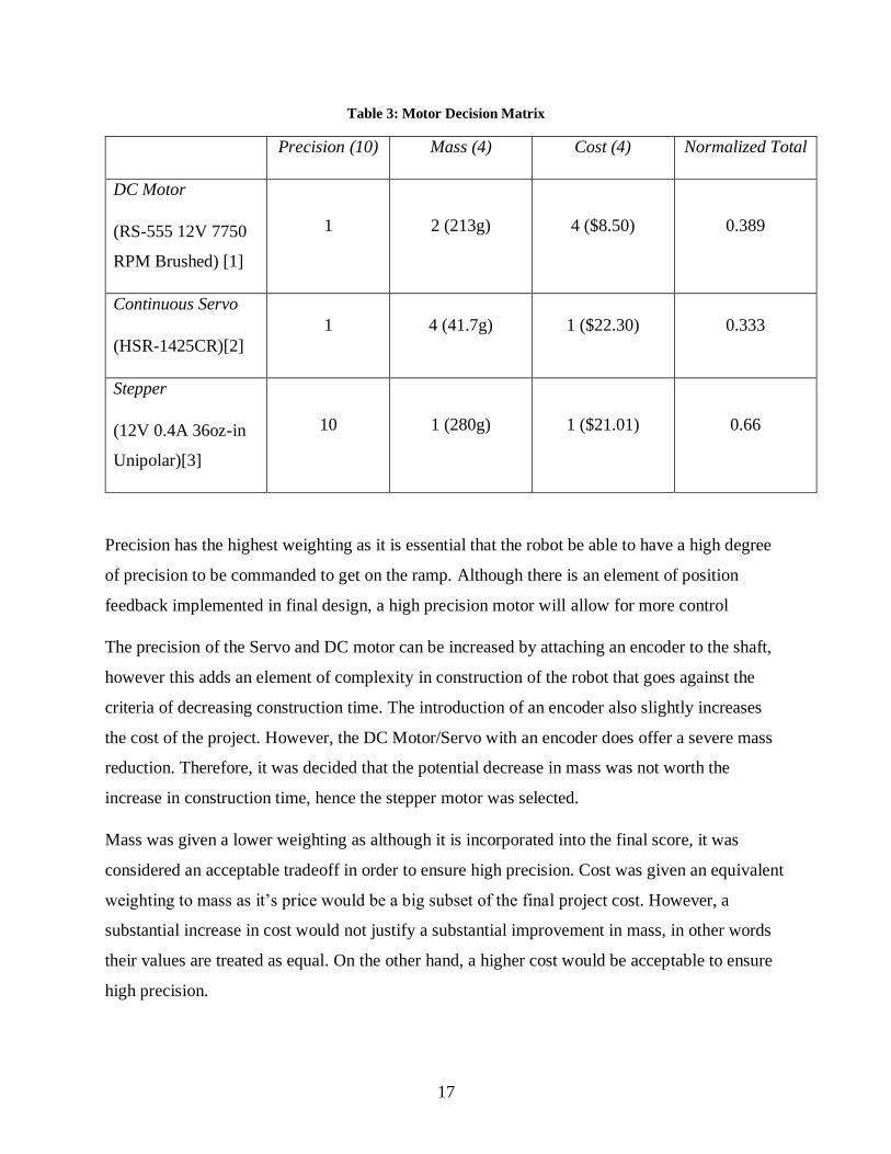
The three types of motors selected above meet all the design constraints of the project. Table 3
below outlines the decision making process in determining which type of motor would be
selected. The scores below are determined by comparing data from different types of motors
obtainable from Robot Shop in Figure 5. The precision was quantified by assuming that since the
DC motor and the continuous servo operate on essentially the same principle and are much less
precise than steppers, they are given the lowest score possible. The decision matrix below in
Table 3 compares the different motors that operate on the required torque range.
17
Table 3: Motor Decision Matrix
Precision (10) Mass (4) Cost (4) Normalized Total
DC Motor
(RS-555 12V 7750
RPM Brushed) [1]
1 2 (213g) 4 ($8.50) 0.389
Continuous Servo
(HSR-1425CR)[2]
1 4 (41.7g) 1 ($22.30) 0.333
Stepper
(12V 0.4A 36oz-in
Unipolar)[3]
10 1 (280g) 1 ($21.01) 0.66
Precision has the highest weighting as it is essential that the robot be able to have a high degree
of precision to be commanded to get on the ramp. Although there is an element of position
feedback implemented in final design, a high precision motor will allow for more control
The precision of the Servo and DC motor can be increased by attaching an encoder to the shaft,
however this adds an element of complexity in construction of the robot that goes against the
criteria of decreasing construction time. The introduction of an encoder also slightly increases
the cost of the project. However, the DC Motor/Servo with an encoder does offer a severe mass
reduction. Therefore, it was decided that the potential decrease in mass was not worth the
increase in construction time, hence the stepper motor was selected.
Mass was given a lower weighting as although it is incorporated into the final score, it was
considered an acceptable tradeoff in order to ensure high precision. Cost was given an equivalent
weighting to mass as it’s price would be a big subset of the final project cost. However, a
substantial increase in cost would not justify a substantial improvement in mass, in other words
their values are treated as equal. On the other hand, a higher cost would be acceptable to ensure
high precision.

18
The decision to select the Soyo 2 Phase 6-Wire Unipolar Stepper motor specifically was largely
determined by its precision, cost and lead time/availability of the motor. Refer to Table 4 below
for the specific parameters of the stepper motor.
Table 4: Important Data Sheet Parameter of Soyo Stepper Motor
Step Angle 1.8o
Step Accuracy ±5% (full step, no load)
Rated Voltage 12V
Current/Phase 0.4A/Phase
Motor Type 6-Wire Unipolar Stepper
Holding Torque 0.254 Nm
Cost $ 21.01
This specific motor met all the torque and volume constraints of the mechanical team, while also
being precise enough to satisfy the requirements of the controls team (200 steps/revolution). The
precision of the motors would be higher than that of the distance sensor used to determine close
loop feedback, hence it was deemed acceptable. This coupled with the fact that it was within the
budget allocated for motors and it was readily available for the construction check is why the
motor was selected.
3.2.1.2 Motor Controller Selection
The section below introduces the need for a dedicated motor controller to drive the stepper motor
selected above. This section also outlines the different motor controllers selected and a brief
explanation of the motor selection.
3.2.1.2.1 Explanation of Theory
A motor controller is needed to properly control the order of which the coils are energized
(stepping the motors) while also supplying an appropriate amount of current needed to drive the
motor. By default, the Arduino Mega R3 is unable to drive the steppers motor needed for the
project as is unable to provide sufficient current to drive the motor at 12 V and 1.6 A (4 Motors
@ 400mA/motor). Figure 6 below outlines the power supply of the Arduino Mega, where “the
regulator output current must not exceed 1.0 A with Vin greater than 12 V” [4][5].

19
Figure 6: Power Supply of the Arduino Mega R3
In order to drive and step the motors using significantly less current, an H-Bridge is used to
abstract the process of supplying power to the motor through a system of transistors that will
handle the switching application. The Arduino would simply switch the transistors on/off
allowing connect the motor to the supply through the transistors (not the Arduino itself). Figure 7
below shows a rough schematic of configuring an H-Bridge using transistors.
Figure 7: H-Bridge Example [6]
Switching TR2 and TR3 on and switching TR1 and TR4 off allows current to flow in the direction
signified in purple. This configuration would significantly reduce the current requirement needed
from the Arduino as it is no longer supplying current needed to drive the motor, simply to switch
transistors. The H-bridge would be connected to a single coil of the motor. Since the motors
selected are 2 Phase Unipolar Stepper Motors, each motor would require two H-Bridges to drive
both coils, resulting in eight H-Bridges needed in total. Also present in Figure 7 above are
Flyback Diodes (D1 – D4) that provide an appropriate path for current to flow when the motor is
suddenly switched off (recall that motors are an inductive load and cannot change current
instantly). These diodes allow for the motors to properly be switched on and off without
damaging the rest of the circuit by providing a path for the reverse current to flow when the
motor is switched off.

20
3.2.1.2.2 Evaluating Alternatives
The motor controller to be selected have the design constraints outlined in Table 5 below.
Table 5: Motor Controller Constraints
Number of Total H-Bridges 2 coils * 4 motors = 8 H-Bridges Total
Output Current (single H-Bridge) 400 mA/phase
Supply Voltage 12V
Output Voltage 12V
Flyback Diodes at Power Transistors Yes
Package for Arduino Mega R3 Compatible Arduino Motor Shield
The first five constraints listed above had been defined in accordance with the specification of
the stepper motors. Only motor shields were considered instead of a set of motor controllers to
avoid having to connect multiple controllers to each motor and connecting these controllers to
the Arduino. Installing a shield onto the Arduino itself reduces the amount of physical wiring
jobs that have to be made, increasing simplicity, reducing construction time and preventing any
potential wiring errors. The slight increase in cost of the motor shields compared to the
individual motor controllers was deemed such an appropriate tradeoff that it was defined as a
constraint.
The stringent design constraints limited the availability of motor shields available to be procured
within an appropriate lead time to allow the team to meet the construction check deadline. The
design criteria used to decide between motor shields were reduction of construction time and
cost. Two motor shields were considered the Adafruit Motor Shield [7] and the iTead Studio
Motor Shield Driver [8]. Both motor shields did not meet the design constraint of total number of
H-Bridges. However, both motor shields allowed for stackable design with each shield
addressable via I2C. The iTead Studio motor shield was slightly more affordable ($5 dollars
less), however the Adafruit Motor Shield provides a significant amount of software libraries that
abstracts interfacing with the stepper motor. This would significantly reduce the time needed to
get up to speed to interface with the motor. The Adafruit Motor Shield also has a significant
community following online that would help reduce debugging time should issues occur,
assuming these are similar issues the community has encountered. The potential decrease in

21
construction time was worth the tradeoff of a slight increase in cost. Table 6 below shows some
the specifications of a single Adafruit Motor Shield and outlines how it meets the design
constraints listed above. Note that two motor shields will be stacked on top of each other using
the I2C bus to properly address the appropriate motor shield.
Table 6: Comparing Adafruit Motor Shield Specifications With Design Constraint
Design Constraint Adafruit Motor Shield
Number of Total H-Bridges 2 coils * 4 motors = 8 H-
Bridges Total
2 shields * 4 H-
Bridges/Shield = 8 total
Output Current (single H-
Bridge)
400 mA/phase 1.2 A/motor (average)
1.5A/motor (peak)
Supply Voltage 12V 12V
Output Voltage 12V 12V
Flyback Diodes at Power
Transistors
Yes Yes
Package for Arduino Mega
R3
Compatible Compatible
3.2.2 Sensor Selection
The controls team required a set of sensors to allow for feedback control to be used in the path
finding and base detecting algorithm. These sensors include a form of a distance sensor as well
as an accelerometer and gyroscope. The design constraints for the sensors were specified by the
controls team. For simplifying the comparison process, all the parts considered below are parts
available from RobotShop that can be attainable within an acceptable lead time (<1 week).
Please note that the mass of the sensors was neglected as the mass of the sensors considered were
all less than 10g, relatively insignificant compared to the mass of the other parts on the robot
(motors = 1.6kg). The section below will outline the design criteria and constraints used to
determine the sensor to be used by evaluating a range of plausible sensors.
3.2.2.1 Distance Sensing
The two design constraints defined by the controls team is that the sensor be able to detect the
distance between the robot and an object in front of it, and that it be small enough to be mounted
on the robot. The design criteria for the distance sensor is to maximize sensing precision,

22
maximize reliability and repeatability of distance measurements while minimizing cost. The
available distance sensors on RobotShop include Ultrasonic Sensors and Infrared (IR Sensors).
3.2.2.1.1 Theory of Operation
Both ultrasonic sensors and infrared sensors rely on an emitter-receiver principle, where the time
between emitting a wave and it bouncing back off the object of interest back to the receiver is
correlated with the distance between objects. They differ in that ultrasonic sensors rely on emit a
sound wave, while IR sensors emit IR waves. Therefore, waves emitted by the ultrasonic sensor
are emitted in a cone like shape see Figure 8 below.
Figure 8: 30 Degree Detection Angle for the Ultrasonic Sensor (HC-SR04) [9]
While waves emitted from the IR sensor are a lot more direct. This means that the IR sensor is
more accurate in detecting distance between two points, the ultrasonic sensor will report the
closest object within the cone emitted. However, IR sensors are more susceptible to noise as it is
sensitive to other frequency or rays in the electromagnetic spectrum. It is important to note that
both sensors struggle with detecting objects that are not directly perpendicular to the sensor
(object is on an angle) as the wave will not be reflected back to the emitter or will be reflected
back with a time offset.
3.2.2.1.2 Evaluating Alternatives
The most popular IR and Ultrasonic sensor obtainable from Robot Shop have been listed below
in Table 7.

23
Table 7: IR vs Ultrasonic Sensor
IR Sensor:
Sharp GP2Y0A60SZ
[10]
Ultrasonic Sensor:
iTead Studio HC-SR04
[11]
Precision 10 – 150 cm 2cm – 200cm
Reliability Low High
Cost $12.26 $3.99
The IR Sensor was given a low reliability score because it is more perceptible to it’s the change
in lighting of it’s environment. Without any filtering this would result in a low repeatability and
reliability. A decision matrix was not created to decide between these two components as the
ultrasonic sensor is the clear winner in each criterion, it has better precision, is more reliable and
cheaper. The downside of the ultrasonic sensor is that due to the larger detection angle any object
within the cone in Figure 8 might be detected though it is not the object of interest. However, this
is easier to compensate for in software than applying significant filtering in the IR sensor.
Specifically, the HC-SR04 was the ultrasonic sensor selected because in addition to being
precise, relatively reliable and low cost, it is also very commonly used sensor with multiple
library support online of which the team has experience interfacing with. This will serve to
reduce time needed to get up to speed with the sensor, reducing construction time.
3.2.2.2 Ramp Sensing
Sensing the ramp requires a sensor that is capable of detecting the orientation of the robot. The
ideal component should be small, have an accelerometer and/or a gyroscope as well as an easy to
use interface. The best sensor for the job is an inertial measurement unit (IMU) as they are small,
contain both an accelerometer and a gyroscope and have built in libraries for easy interfacing
with an Arduino. Due to the slow moving nature of the robot, the controls team did not see a
need for any specialized high accuracy IMUs. The best course of action would be to find am
IMU that is affordable and easy to use. Since many of the other parts were selected from Robot
Shop’s inventory, it makes sense to purchase the IMU from the same place. The cheapest IMU
on Robot Shop is the MPU6050 [12]. A summary of the features is listed in Table 8.

24
Table 8: Electric Properties of the MPU6050
Working Voltage 3-5 V
Current Draw 3.9 mA
Sensors Accelerometer, Gyroscope
Interface I2C
The MPU6050 may be one of the most basic IMUs but it is more than enough for the purpose of
ramp sensing. It contains both an accelerometer and a gyroscope and has built in I2C libraries for
easy interfacing with the Arduino. Furthermore, the working voltage and current draw are well
within the limitations of the power supply which means that it is the best choice for the job.
3.2.3 Power
The following section outlines the decisions involved in selecting a power supply based on the
power consumption of the robot.
3.2.3.1 Explanation of Theory
In order to properly build an independent robot, a portable power supply must be chosen over a
non-portable alternative. Furthermore, the size constraint of the robot means that smaller sources
are much more suitable for the job. The system requires 12V to properly power and needs to last
long enough to traverse to the destination with a large margin to spare.
Two methods were considered when deciding on the method to achieve the necessary 12V
required for the system. The first and simplest method that was considered is using a 12V battery
pack. The second method is using the combination of a lower voltage battery and a boost
converter to reach the necessary 12V.
3.2.3.2 Power Requirements
In order to decide on a battery pack, the power requirements need to be found. It has already
been established that the required voltage is 12V but the current must be calculated to determine
the lowest voltage source that can be used to generate 12V with a boost converter. It is also
required to determine how long a supply will last under the load.
To determine the current usage, the individual usage of each peripheral can be added together.
The stepper motors are rated for 400 mA per phase so in a two phase motor, 800mA draw is the

25
worst case scenario. The worst case scenario for the other peripherals is the current draw when
they are in use. Table 9 below depicts the current draw of the components
Table 9: Current Draw of Robot Components
Peripheral Current Draw Quantity Total Current Draw
Ultrasonic 15 mA
[9] 4 60 mA
Stepper Motor 800 mA [13] 4 3200 mA
MPU 3.9 mA [14] 1 3.9 mA
The total current draw is 3263.9 mA which is a very large current draw. A boost converter would
have a hard time boosting the voltage to 12V in this scenario unless the input voltage was
already close to 12V. After running simulations in LTSpice to boost various voltage supplies to
12V, it is found that 9.1V is the minimum voltage required from the supply to output the
necessary current at the 12V level. Figure 9 shows that a 9.1V supply is able to provide the
necessary current while Figure 10 shows that a 9V supply is unable to reach the necessary
current level.
Figure 9: Drawing 3263.9 mA of Current from a 9.1V to 12V Boost Converter
Figure 10: Drawing 3263.9 mA of Current from a 9V to 12V Boost Converter

26
Any lower voltage source is unable to hold the current to the necessary level. Unfortunately,
9.1V battery packs are very rare so the more common 9.6V battery is suitable as an alternative.
This also increases the margin of allowable error for the current draw. Table 10 compares the
batteries:
Table 10: Comparison between 12V Battery and 9.6V battery Boost Converter System
9.6 V Battery Pack and Boost
Converter Combo [15] Boost Converter [16] 12 V Battery Pack [17]
Charge 1600 mAh N/A 1600 mAh
Mass 0.200 kg N/A 0.251 kg
Price $42.45 CAD $6.66 CAD $41.03 CAD
In a direct comparison of quantitative properties, it can be seen that the 9.6V battery and boost
converter combination is fairly similar to the 12V battery. Not only is the difference in the
charge non-existent, the mass and price differences are negligible.
The reason the 12V battery pack was chosen as the power supply of choice is because it allows
for the most simplistic design and therefore minimizes risks with the full system. This benefit is
very difficult to quantify but adding a boost converter would require far more work which would
include the design of a voltage boosting system, acquiring SMD components to build the system,
soldering components on a new board and integrating the board into the existing system.
Figure 11 and Figure 12 depict the difference in complexity between the 9.6V battery pack and
boost converter compared to having the 12V battery pack. It is very clear to see that boost
converter requires much more work and poses a much higher risk of causing problems with the
operation of the robot.

27
Figure 11: Schematic of 9.6V Battery and Boost Converter System
Figure 12: 12V Voltage Supply
The voltage and current values in Figure 13 to Figure 16 show that the 12V battery pack is
already 12V in nature so it will output a perfectly flat signal when the robot is running. In
contrast, the boost converter has inductance and capacitance in the system that causes a delay of
around 1ms before settling into the correct transient state. Although the transient state is too short
to noticeably affect the performance of the robot, the use of a lower voltage supply increases the
risk of power failure when a sudden spike in current draw occurs.

28
Figure 13: 12V Battery Voltage Level under Full Load
Figure 14: 9.6V Battery and Boost Converter Voltage Level under Full Load
Figure 15: 12V Battery Current Level under Full Load
Figure 16: 9.6V Battery and Boost Converter Current Level under Full Load
3.3 Control System Design
The following section documents the design decisions made regarding the controls aspect of the
robot. For flexibility, control algorithm design has been abstracted to avoid implying specific
electrical or mechanical solutions where possible.
29
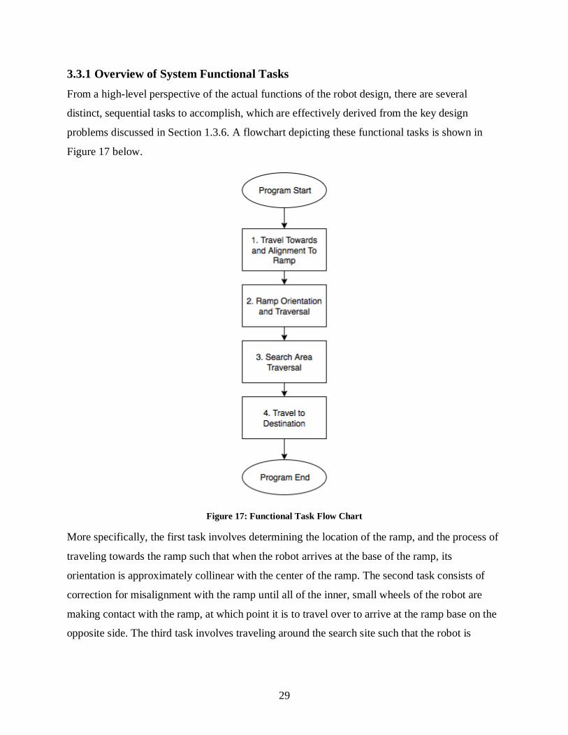
3.3.1 Overview of System Functional Tasks
From a high-level perspective of the actual functions of the robot design, there are several
distinct, sequential tasks to accomplish, which are effectively derived from the key design
problems discussed in Section 1.3.6. A flowchart depicting these functional tasks is shown in
Figure 17 below.
Figure 17: Functional Task Flow Chart
More specifically, the first task involves determining the location of the ramp, and the process of
traveling towards the ramp such that when the robot arrives at the base of the ramp, its
orientation is approximately collinear with the center of the ramp. The second task consists of
correction for misalignment with the ramp until all of the inner, small wheels of the robot are
making contact with the ramp, at which point it is to travel over to arrive at the ramp base on the
opposite side. The third task involves traveling around the search site such that the robot is

30
eventually able to detect and determine the location of the destination base relative to itself. The
final task involves converging upon and moving to the location of the destination base.
Traversal to the ramp and traversal within the search area can both be achieved through
determining the robot’s location in the environment, which is therefore to be accomplished via a
distance sensing algorithm. Ramp orientation and traversal is mainly concerned with remaining
on the ramp in a straight orientation.
3.3.2 Distance Sensing Algorithm
The objectives for the distance sensing algorithm are mainly relevant to identifying the robot’s
orientation and position relative to some reference object(s) in the environment and identifying
how movement can be controlled or directed to achieve a desired or commanded relative
orientation and position. When this algorithm is applied during the task of traveling to the ramp,
its role is to minimize the difference between the current distance from the robot’s center to the
center of the ramp, as well as the angle between the robot’s trajectory and the center of the ramp.
In a similar manner, when the robot is performing the task of searching for the base in the
specified search area, the algorithm’s function is to minimize positional error and angular
deviation from a pre-planned path as it travels through the area, until the base has been detected.
3.3.2.1 Sweeping Algorithm
The sweeping algorithm involves mapping the surroundings with one distance sensor that sweeps
separately in front or with the robot. During the sweep, multiple measurements are made to
create a representation of the objects and obstacles that are in front or around it. Based on this
information, the distances to the surrounding objects is mapped and can be used to guide the
robot within the confined perimeter. In Figure 18 below, the geometry to calculate the distance
between an object and the robot is shown. This assumes that the sensor sweeps together with the
robot.

31
Figure 18: Sweeping Algorithm Diagram
From the above, the distance of the robot from the object in the x direction and y direction can be
evaluated from the two edge distance inputs (d1 and d2) and the known rotation angle () from
the object. The two relations are stated below:
𝑦 = (R+d1)(R+d2)sin (𝜃)
(𝑅+𝑑1)2+(𝑅+𝑑2)2−2(𝑅+𝑑1)(𝑅+𝑑2)cos (𝜃)
𝑥 = √(𝑅 + 𝑑1)2 − 𝑦2 − [(𝑅 + 𝑑1)2 + (𝑅 + 𝑑2)2 − 2(𝑅 + 𝑑1)(𝑅 + 𝑑2) cos(𝜃)]
Based on this information, the robot is able remain within the perimeter of the competition and
identify the ramp. In addition, by pre-mapping the expected map data on the other side of the
mountain, any discrepancies and be attributed to identifying the targeted base.
3.3.2.2 Boundary Offset Algorithm
The boundary offset algorithm relies on both the robot’s location relative to the boundary walls
and its forward heading angle with respect to the walls. There are two main underlying
assumptions to this algorithm: that the boundary walls are reasonably straight (no more than
approximately 5 degrees of angular deviation per meter of boundary length), and that the
boundary walls are close to parallel to the ramp (no more than approximately 5 degrees of
angular deviation from a line parallel with the ramp’s center in 1 meter of the boundary wall
leading up to the ramp).

32
Defining the direction of the search area on the opposite side of the mountain range wall as
north, the east boundary wall is selected as a reference when traveling to the ramp. Therefore, the
reference distance measurements are always to be taken from the robot’s right-facing side (i.e.
the direction 90 degrees clockwise from its forward traveling direction), both when traveling to
the ramp and when searching the area on the opposite side of the mountain range wall. Two
reference distance measurements are necessary in order to determine both angular orientation
and shortest distance with respect to the reference boundary edge. Taken in conjunction with the
dimensions of the robot, this information can then be used to compute both the shortest distance
from the center of the car to the closest reference boundary edge detected on the robot’s right-
facing side, and its angular orientation with respect to that boundary edge, where the former is
based on an average of the two distance measurements and the latter is based on the difference of
the two distance measurements. This configuration is shown in Figure 19 below.
Figure 19: Boundary Offset Algorithm Diagram
Based on the above configuration, the distance (d) and the angle () can be calculated based on
the input distances (d1 and d2). The two relations are stated below:
𝑑 = 𝑑3 +𝑤
2sin(𝜃) 𝑤ℎ𝑒𝑟𝑒 𝑑3 =
𝑑1 + 𝑑2
2
𝜃 = cos−1(𝑑1 − 𝑑2
𝑦)

33
3.3.2.3 Distance Sensing Algorithm Evaluation
One of the main design criteria relevant to the selection of a distance sensing algorithm is
execution time. However, there is inherent difficulty in accurately estimating the run time of
each alternative prior to actually implementing them, thus a more generalized, qualitative
approach is taken to compare the execution times. The sweeping distance sensing algorithm is
concluded to require significantly more time to acquire the same relative position and angle data,
as it requires additional rotations between non-simultaneous distance measurements, as opposed
to the boundary offset distance sensing algorithm, which can obtain both of its measurements
simultaneously and without additional movement. This corresponds to an increase in overall
execution time for the sweeping algorithm, both during travel to the ramp and the search for the
destination base.
The simultaneity of the distance measurements required by the boundary offset algorithm carries
the disadvantage of requiring an additional sensor, which corresponds to an increase in the
overall device’s weight. However, this increase is insignificant in magnitude compared to the
other components as discussed in Section 3.2.2 thus this is considered to be an acceptable
tradeoff for the decreased execution time. In addition, assuming no change in the amount of
sensor data processing and filtering between the two distance sensing algorithms, there is
intuitively some additional uncertainty added by the sweeping algorithm, as the intermediate
rotation of the robot between sensor measurements introduces the possibility for some small
error due to wheel slipping or small position changes. As a result of the general overall benefits
of the boundary offset algorithm, it is selected over the sweeping algorithm for the purposes of
distance sensing.
3.3.3 Ramp Securing Algorithm
The purpose of the ramp securing algorithm is to detect and correct for initial misalignment of
the robot’s appropriate wheels with the ramp such that it travels up the ramp on the smaller
wheels and uses the larger wheels as supporting guides. This is only applicable during the initial
transition onto the ramp, after which it is assumed that the mechanical solution of staggered
wheel sizes will be sufficient to keep the robot’s trajectory on the ramp in the correct direction.
Regardless of the ramp securing algorithm selected, the direction of misalignment must be
identified, after which the robot is to drive in reverse until completely off of the ramp, before

34
correcting its orientation slightly based on the misalignment and attempting to climb the ramp
once more, repeating until no misalignment is detected. This incremental repetition is to ensure
precision, as the small width of the wheels allows for easy overshoot.
3.3.3.1 Tilt Detection Algorithm
The basis of the tilt detection algorithm is the rather intuitive detection of tilt about its central
forward facing axis, also known as roll. Upon detection of non-negligible roll, the robot is simply
to reverse until off of the ramp, shift over in the direction opposite of the roll detected, and retry
climbing the ramp.
3.3.3.2 Motor Current Monitoring Algorithm
The motor current monitoring algorithm relies upon the physical principle that motor torque is
proportional to current draw. As the robot initially climbs up the ramp, misalignment of the
appropriate wheels with the ramp will lead to either one of the front wheels losing contact with
the ground, causing a significant decrease in the torque applied to the corresponding motor and
therefore significantly reduced current draw through that motor. As with the tilt detection
algorithm, the robot is to reverse off of the ramp and shift in the direction opposite of the side
where reduced current was detected before re-attempting to climb the ramp.
3.3.3.3 Ramp Securing Algorithm Evaluation
The most significant difference of importance between the two algorithms is related to design
and construction complexity. Motor current monitoring requires current draw sensing on both of
the front motors, whereas tilt detection merely requires monitoring of roll of the robot as a
whole, meaning that the tilt detection algorithm necessitates less sensors in the design, and also
thereby eliminates any error from unequal noise or measurements in the case of multiple sensors.
Furthermore, current sensing implies a need for additional circuitry components such as a sense
resistor to measure the voltage across, while the tilt detection algorithm can work directly off of
the roll measurement given by a sensor such as a simple gyroscope. As a result, the tilt detection
algorithm is selected as the superior alternative.
3.3.4 Destination Base Detection Algorithm
The destination base detection algorithm is to be applied in parallel with the distance sensing
algorithm when the robot is in the process of searching for the destination base on the opposite
side of the mountain range. Its purpose is to detect the existence of the destination base and

35
subsequently to provide information regarding the base’s location and how the robot is to travel
there.
3.3.4.1 Reference Distance Data Comparison Algorithm
The reference distance data comparison algorithm reuses the concept of distance sensing to
determine when the destination base is detected. Assuming the robot is also simultaneously using
the boundary offset distance sensing algorithm described in Section 3.3.2.2, two distance
measurements will be constantly taken on the right-facing side of the device. Taking a distance
measurement from the rear side of the robot will not be particularly useful for detecting the base,
as the collected data would only be relevant to regions where the robot had previously traveled.
Therefore, distance measurements will be taken from the front and left-facing sides of the robot.
The basis for the reference distance data comparison algorithm is the underlying assumption that
the entire search and rescue site area will not physically change over time to any non-negligible
extent. Based on this assumption, this algorithm involves first running a series of pre-execution
runs, in which the robot is to travel along a pre-planned path around only the search side of the
mountain range wall, where the destination base has first been removed, and collect a series of
distance measurements from its front and left-facing sides as it travels for each run. The number
of runs to repeat must be significant (at least 30), and the distance measurements taken will be
averaged and filtered across the various runs to remove outlying data and improve accuracy. The
resulting data is then to be used as reference data for comparison when the actual search
operation is performed. In this case, the robot is still to travel along the same pre-planned path
through the search area, but when a distance measurement is taken that varies significantly from
the reference data obtained in the absence of the destination base’s existence, this measurement
indicates the existence of the base and also provides information on its location relative to the
device. At this point, the robot is to use this information to determine an approximate initial
bearing to take to approach the destination base, and will switch over to the basic distance
sensing algorithm selected in Section 3.3.4 to target and travel to the base.
3.3.4.2 Extended Arm Deflection Sensing Algorithm
The extended arm touch sensing algorithm involves the concept of physically contacting the base
in order to know exactly where the base is. The theory of operation is that a retractable arm

36
driven by a servo motor will start to extend from the robot out into the open space as shown
below in Figure 20.
Figure 20: Extended Arm Sensor
This creates an arm for the robot that will search the area in front of the robot through touch,
much like a cane for those with visual disabilities. As the robot rotates, the arm will extend to the
extents of the search area on the other side of the wall. The extended arm will be a flexible arm
that will deflect once it touches the object as the robot continues to rotate. This deflection will be
measured by an additional distance sensor, which will allow the robot to know when the base has
been detected, and can also be used to compute the direction that must be taken to approach the
base.
3.3.4.3 Destination Base Detection Algorithm Evaluation
The extended arm deflection sensing algorithm possesses an advantage over the reference
distance data comparison algorithm in that it will likely require less time to detect the destination
base, although this is under the assumption that there is no limit on both the length of the
extension arm and the maximum distance measurement that can be taken. This is based on the
necessity to travel around the entire search area in the case of the distance data comparison
method, whereas the arm deflection method ideally requires only a single rotation of the robot to
locate the base. However, the distance data comparison algorithm also precludes the need for an
additional motor, which would be required to extend the arm, as well as the arm itself, which
provides the distance data comparison method with a significant advantage in terms of

37
minimizing weight. Furthermore, the addition of the extension arm requires additional
mechanical design and complexity in modeling the deflection of the extension arm accurately,
which in turn increases uncertainty in the relative location of the destination base. Thus, the
reference distance data comparison algorithm is taken as the selected base detection algorithm.
3.4 Testing
The proposed test plan for the designed robot begins by validating each of the basic components
of the robot. This includes testing the motors as the robot is moving, the correctness of the IMU
measurements, and the distance measurements received from the ultrasonic sensor. Testing the
motors include testing the robot travelling on the floor in any direction as well as the robot
travelling up and down the ramp. For the IMU, the test required is to validate the sensor’s results
as the robot in moving up and down the ramp. Lastly, for the ultrasonic sensor, the test required
is to determine the minimum hold time for the sensor to obtain an accurate measurement to an
object, its precision, as well as its minimum and maximum range. After the basic components of
the robot are tested, the ramp and base detection algorithms must be tested. This will involve
how the robot detects the ramp and base by differentiating from the surroundings as well as
testing the algorithm from different angles of approaches.

38
3.5 Summary of Final Design
Shown below in
Figure 21 is an exploded view of the final design with the major design parts labeled. For the full
assembly drawings refer to Appendix B.

39
Figure 21: Final Design Exploded View
The bill of materials for the major components is listed in Table 11 below. For the
comprehensive Bill of Materials please refer to Appendix B.

40
Table 11: Major Parts Bill of Materials
Item Number Part Number Quantity Source
1 Hammond 1591 E 1 Sayal
2 Hammond 1591 D 1 Sayal
3 60 mm Pololu Wheel 4 Creatron
4 80 mm Pololu Wheel 4 Creatron
5 Hub 4 Creatron
6 Arduino Mega 2560 1 Adafruit
7 HC-SR04 Ultrasonic 4 Robot Shop
8 6 DOF Gyro,
Accelerometer IMU
1 Robot Shop
9 12 V 0.4 A Unipolar
Stepper Motor
4 Robot Shop
10 Ni-Mh Battery 1 Robot Shop
11 Motor Shield 2 Adafruit
3.5.1 Expected Performance
Knowing that the maximum range of the selected ultrasonic sensors is 500 cm [9], the path that
must be traveled by the robot on the search site side of the mountain range wall is determined,
and the distance traveled on that side is determined to be 185.39cm. Assuming that the starting
base is located at the furthest edge of the starting side of the mountain range wall and the
trajectory of its travel to the ramp will be purely orthogonal or parallel to the ramp and wall, the
distance traveled on the starting side is 135.77cm. The complete trajectory is shown in Figure 22
below.

41
Figure 22: Complete Trajectory of the Robot
The combined ground travel distance is therefore 321.16 cm. Knowing that the operating speed
of the stepper motors is 90 rpm [12], and that the robot will always be traveling on the outer 8.0
cm diameter wheels while on the ground, the robot’s ground speed will be 2261.95 cm/min or
37.70cm/s. Therefore, the robot’s combined ground travel time is 8.50 s.
The robot’s ramp travel distance is 186.69 cm per incline in addition to the 32.24 cm segment at
the top of the ramp, giving a total ramp travel distance of 405.62 cm. Using the same motor
operating speed of 90 rpm and knowing that the robot will be traveling on the inner 6.0 cm
diameter wheels while on the ramp, the robot’s ramp speed is determined to be 1696.46cm/min
or 28.27cm/s. Therefore, the robot’s total ramp travel time is 14.35 s, and the overall travel time
is 22.85 s.
The battery used will allow for the robot to last 0.49 hours, which is sufficient time to allow the
robot to run with the for the estimated travel time as well as allow for multiple rounds of testing
without having to recharge.

42
4 Conclusions and Recommendations
The mechanical design for the final device includes a store-bought enclosure, and staggered
inner and outer wheels with 60 mm and 80 mm respective diameters used as a ramp guiding
mechanism. The electrical design includes selection of an appropriate stepper motor, the Adafruit
motor shield for the Arduino, ultrasonic sensors for distance measurement, an economical
inertial measurement unit for ramp sensing and a 12 V power supply. The control system design
uses a boundary offset algorithm for distance sensing, a tilt detection algorithm for ramp
alignment and a reference distance data algorithm for destination base detection.
Basic commissioning and component verification should be performed next, followed by
integration and basic functionality testing. More detailed sensor testing should also be performed
for metrics including required hold time and actual sensor range and resolution, particularly for
the ultrasonic sensors.

43
5 References
[1] RobotShop (2016). RS-555 12V 7750 RPM Brushed DC Motor [Online]. Available:
http://www.robotshop.com/ca/en/rs-555-12v-7750-rpm-brushed-dc-motor.html
[2] RobotShop (2016). HSR-1425CR Continuous Rotation Servo [Online]. Available:
http://www.robotshop.com/ca/en/hitec-hsr-1425cr-continuous-rotation-servo.html
[3] RobotShop (2016). 12V 0.4A 36oz-in Unipolar Stepper Motor (double shaft). [Online].
Available: http://www.robotshop.com/ca/en/rbsoy07-soyo-unipolar-stepper-motor.html
[4] Arduino (2016). Arduino MEGA 2560 [Online]. Available:
https://www.arduino.cc/en/uploads/Main/arduino-mega2560_R3-schematic.pdf
[5] ON Semiconductor (2016). NCP1117, NCV1117 [Online]. Available:
http://www.onsemi.com/pub_link/Collateral/NCP1117-D.PDF
[6] Imgur (2011, February 3). H-Bridge Schematic [Online]. Available:
http://i.imgur.com/Se8D3.jpg
[7] Adafruit Industries. Adafruit Motor Shield V2 for Arduino [Online]. Available:
https://learn.adafruit.com/adafruit-motor-shield-v2-for-arduino/overview
[8] RobotShop (2016). Dual Stepper Motor Driver Shield for Arduino [Online]. Available:
http://www.robotshop.com/en/dual-stepper-motor-driver-shield-arduino.html
[9] RobotShop (2016). HC-SR04 Ultrasonic Range Finder [Online]. Available:
http://www.robotshop.com/ca/en/hc-sr04-ultrasonic-range-finder.html
[10] RobotShop (2016). 5V Pololu Carrier w/ Sharp GP2Y0A60SZ IR Range Sensor - 10 to
150cm [Online]. http://www.robotshop.com/ca/en/5v-pololu-carrier-sharp-gp2y0a60sz-ir-range-
sensor-10-150cm.html
[11] ITead Studio (2010, March 11). Ultrasonic ranging module : HC-SR04. Available:
http://www.robotshop.com/media/files/pdf/datasheet-sen026.pdf
[12] RobotShop (2016). 6 DOF Gyro, Accelerometer IMU - MPU6050 [Online]. Available:
http://www.robotshop.com/ca/en/6-dof-gyro-accelerometer-imu-mpu6050.html

44
[13] RobotShop (2016). Soyo 12V 0.4A 36oz-in Unipolar Stepper Motor Specifications [Online].
Available: http://www.robotshop.com/media/files/pdf/rb-soy-03-unipolar-stepper-motor-
specs.pdf
[14] InvenSense (2013, August 19). MPU-6000 and MPU-6050 Product Specification Revision
3.4 [Online]. Available: https://www.cdiweb.com/datasheets/invensense/MPU-
6050_DataSheet_V3%204.pdf
[15] RobotShop (2016). 1600mAH 9.6V NiMH Square Battery Pack ELCO [Online]. Available:
http://www.robotshop.com/ca/en/hitec-54114--battery.html
[16] Linear Technology (2016). LT3579/LT3579-1 6A Boost/Inverting DC/DC Converter with
Fault Protection [Online]. Available: http://cds.linear.com/docs/en/datasheet/35791fa.pdf
[17] RobotShop (2016). 12V 1600mAh Rechargeable NiMh Battery [Online]. Available:
http://www.robotshop.com/ca/en/12v-1600mah-rechargeable-nimh-battery.html

45
Appendix A – Static Coefficient of Friction Verification
An experiment was performed to verify the static coefficient of friction of the rubber
wheels on plywood. A block of wood was used to represent the body of the vehicle and
the wheels were attached by drilling holes into the wood where the screws on the wheel
were inserted. The mass used doesn't matter because the formula for finding static
coefficient of friction is µs=tanθ, and only depends on the angle where slipping occurs. A
piece of plywood was used to represent the ramp and a phone was taped to the plywood
with an app that would tell us the angle that the wood was at. The setup can be seen in
Figure 23.
Figure 23: Test setup for finding the coefficient of static friction
The experiment was done by placing the model vehicle on different locations on the
plywood each time and raising the plywood until the vehicle started to move, and
recording the angle this occurred at. This was repeated 10 times and on average it was
found that the vehicle slipped at an angle of 41.3°, which corresponds to a static
coefficient of friction of µs=0.878, using µs=tanθ.

46
Appendix B – CAD Drawings
Figure 24 to Figure 27 below outline all the mechanical CAD Drawings for the enclosure that
holds all the parts for the final robot together.

47
Figure 24: Bottom Enclosure

48
Figure 25: Battery Holder

49
Figure 26: Enclosure Lid

50
Figure 27: Enclosure

51
1
2
3
4
5
6
7
8
9
10
11
12
13
14
15
16
17
23
19
19
20
21
19
19
0
Downfall AssemblyDrawing
Downfall
HUBRIS
02/29/16
02/29/16
02/29/16Jasdeep
Anthony
Jeremiah
WEIGHT:
A3
SHEET 1 OF 1SCALE: NOT TO SCALE
DWG NO.
TITLE:
REVISIONDO NOT SCALE DRAWING
MATERIAL:
DATESIGNATURENAME
DEBUR AND
BREAK SHARP
EDGES
FINISH:UNLESS OTHERWISE SPECIFIED:
DIMENSIONS ARE IN MILLIMETERS
SURFACE FINISH:
TOLERANCES:
LINEAR:
ANGULAR:
Q.A
MFG
APPV'D
CHK'D
DRAWN

52