designing very strong gear teeth by means of high ......gear design to meet both design criteria...
TRANSCRIPT

(The statements and opinions contained herein are those of the author and should not be construed as an official action or opin-ion of the American Gear Manufacturers Association.)
Introduction and BackgroundBy convention, commonality of cutting tools, and familiarity, several pressure angle choices have become industry standards for gear designs. These include 14.5, 20, 22.5 and 25° pressure angles. Twenty and 25° pressure angle gears are typically the most commonly used today, although pressure angles as high as 28° to 30° have been used on occasion for maximum-strength applications.
Higher pressure angle designs were typically not considered or used because of the limitations listed above, the most significant being reduced gear teeth top lands and fillet radius. Standard gear tooth proportions and universal rack geometry are based on the pressure angles listed above and do not lend themselves to designing gears with pressure angles above around 30°.
For higher pressure angle gear designs, numbers of teeth and other gear tooth macro-geometry items must be considered carefully so that the natural limitations of high pressure angle gearing are avoided while exploiting their benefits.
If not carefully designed, manufacturing the gears can be dif-ficult and more expensive. Gear cutting tools will usually be non-standard. Gear noise will usually be higher due to the decreased contact ratio and reduced root/tip clearance, which can entrap oil.
Separating force from the gear teeth increases directly with the tangent of the pressure angle. In parallel shaft assemblies, this needs to be considered, as the increased forces arising from high pressure angle gears may unacceptably shorten shaft or bearing life. In planetary gearboxes, the net separating force is theoretically zero: the sun/planet separating force is canceled out by the planet/ring separating force. Therefore, planetary appli-cations offer an excellent opportunity to utilize higher pressure angle gear teeth.
The advantage of the methods described in this paper is that
gear teeth and gear tooth data of various different pressure angles can be calculated, compared and evaluated quickly and easily, and high pressure angle gears can be designed and speci-fied. Gears can be designed based on desired top lands, contact ratio, and hob tip radius.
DiscussionAs stated above, two of the primary attributes of high pressure angle gears that are potentially limiting factors and therefore must be considered, calculated, and accounted for are: 1) circu-lar tooth thickness at the outside diameter of the gear (top land thickness); and 2) hob tip radius and the resulting generated tooth root fillet radius; both of these are considered — each in a separate section.
In this report four separate gear tooth pairs are evaluated and described:1. Traditionally designed gearset with 25° pressure angle serving
as reference design2. High pressure angle gearset with hob tip radius of zero and
36° pressure angle3. High pressure angle gearset with a 0.007 inch hob tip radius
and 35° pressure angle4. High pressure angle gearset with a 0.020 inch hob tip radius
and 33.5° pressure angle
To ease in the evaluation and comparison, and to isolate the pressure angle influence on the results so that pressure angle is the main variable, the following inputs remain the same for both the traditional 25° pressure angle design and the high (maxi-mized) pressure angle design:
Numbers of gear and pinion teeth; diametral pitch; center dis-tance (standard center distance); the circular tooth thickness of pinion and gear for the high pressure angle gears is equal and is set by the backlash. The 25° pressure angle reference design uses 15% long addendum pinion and 15% short addendum gear tooth proportions and the resulting gear tooth circular tooth thicknesses to provide close to equal bending stresses for the
Designing Very Strong Gear Teeth by Means of High Pressure AnglesRick MillerThe purpose of this paper is to present a method of designing and specifying gear teeth with much higher bending and surface contact strength (reduced bending and surface contact stresses). The primary means of achieving this is by specifying gear teeth with significantly higher pressure angles. This paper will show calculation procedures, mathematical solutions, and the theoretical background and equations to do this. The required user input factors for the method described in this paper are: numbers of teeth, pinion and gear; diametral pitch; center distance; desired minimum top land, pinion and gear; desired contact ratio; and maximum backlash. The desired pressure angle can then be entered and another value re-entered to make comparisons. The output factors would be the outside diameters of the pinion and gear, and other gear data, based on the entered pressure angle. In the past, higher pressure angle gears have not been commonly designed and specified because of the relative difficulties involved in designing them and the lack of appropriate and easy-to-use tools to evaluate them. This paper contributes to making it easier to accomplish this task.
Printed with permission of the copyright holder, the American Gear Manufacturers Association, 1001 N. Fairfax Street, Fifth Floor, Alexandria, VA 22314-1587. Statements presented in this paper are those of the author(s) and may not represent the position or opinion of the American Gear Manufacturers Association.
66 GEAR TECHNOLOGY | June 2017[www.geartechnology.com]
technical

pinion and gear. This represents a typical relatively standard gear design.
Program user inputs• Number of teeth, pinion and gear: z1, z2• Diametral pitch: Pd• Center distance (default = standard): a• Desired minimum top land, pinion and gear: ToP, ToG• Desired contact ratio: mc• Maximum backlash: B
Summary of user inputs for example of high pressure angle gear set run• 16 tooth pinion, 29 tooth gear• 6 diametral pitch• 3.75 inch center distance (standard)• Desired minimum top land, pinion and gear: 0.030 inch• Desired contact ratio: 1.15• Maximum backlash: 0.0120 inch
Definition of terms (Note: Subscripts P = pinion; G = gear, where necessary.) z1, z2 = Number of teeth DbP = Base diameter, pinion DbG = Base diameter, gear Pd = Diametral pitch DoP = Outside diameter, pinion DoG = Outside diameter, gear d = Pitch diameter to = Circular tooth thickness at outside diameter (or any
known diameter) a = Center distance pb = Base pitch DR = Root diameter Z = Length of line of action mc = Contact ratio ϕ = Pressure angle ϕo = Pressure angle at outside diameter (or any known
diameter) s = Circular tooth thickness at standard pitch diameter
Calculations for pressure angle corresponding to input top land (tooth thickness at O.D.) and contact ratio, mc
Mathematical solution:(1)
Do =d cos ϕ
cos (arcinv( s – to + inv ϕ))d Do
(2)
Mc =Pd (√(DoP)2
– (DbP)2+√(DoG)2
– (DbG)2– a sin ϕ)2 2 2 2
π cos ϕ
Standard gear equations used:
d = zPd
Db = d cos ϕ
pb =(π cos ϕ)
Pd
s = π – B2Pd 2
Calculation procedure. Using input information and stan-dard gear equations above, calculate d, Db, and s for pinion and gear. Since pressure angle is the unknown, create an initial trial
value and substitute Equation 1 (above). Because the Do term appears in the denominator as well as being the unknown vari-able solved for, the denominator value is set to the standard Do
value. Because the contribution of this term is small, the poten-tial “error” that this causes is negligible to the end calculation. Calculate the outside diameter Do for both pinion and gear from Equation 1.
Next, substitute the Do values calculated from Equation 1 into Equation 2, and calculate the contact ratio at that pressure angle. Iterate the pressure angle and calculate using Equations 1 and 2 to converge on the desired contact ratio that was input. The result is the pressure angle necessary to achieve the desired con-tact ratio, top land, and also meet other input conditions.
Derivation of EquationsOutside diameter. Since top land is known by user input and
circular tooth thickness s is known by calculation from inputs or as a separate input, Equation 3 can be solved for Do:
(3)to = Do ( s + inv ϕ – inv ϕo)d
Solve Equation 3 for inv ϕo:(4)
inv ϕ = s – to + inv ϕd Do
The involute function is inv ϕ = tan ϕ – ϕ radians. If the numeric value of inv ϕ is known and the angle is desired, this contains a transcendental term, and the solution must be iter-ated using the Newton method; the result is called “ARCINV.” Look up or solve for the angle of the ARCINV.
(5)cos ϕo = (
d cos ϕ)Do
(6)... Do = (
d cos ϕ )cos ϕo
Substituting Equation 4 into Equation 6:(7)
Do =d cos ϕ
cos (arcinv( s – to + inv ϕ))d Do
Contact ratio:(8)mc = ( z )Pb
But Equation 9:(9)
pb = ( π cos ϕ )Pd
and Equation 10:(10)
Z =√(DoP)2 – ( DbP)2
+√(DoG)2 – ( DbG)2
– a sin ϕ2 2 2 2
Combining Equations 8, 9 and 10 gives:(11)
mc =Pd(√(DoP)2
– ( DbP)2+√(DoG)2
– ( DbG)2– a sin ϕ)2 2 2 2
π cos ϕ
Any other pressure angle can be entered and another value re-entered to make comparisons.
A spreadsheet or computer program can be created from the equations and formulas included in this paper to automate the
67June 2017 | GEAR TECHNOLOGY

mathematical calculations.As stated above, the result of this convergence routine shows
the pressure angle for the gearset above with the design input values, considering the input value for top land thickness.
However, as also stated above, the second important consider-ation is the hob tip radius and the root fillet radius it generates for both the pinion and gear. The pressure angle for this con-sideration is almost certainly different from the pressure angle considering the pinion and gear top land only. So, in order for a gear design to meet both design criteria (matching the top lands and hob tip radius/tooth root fillet radius), the smaller of the two pressure angle values must be used in the design of the gear teeth.
All gear data and stress calculations were performed using the AGMA GRS 3.1.7 gear rating suite program. Due to the length of the program data outputs, the data was summarized and shown in a more abbreviated format.
Result of calculation for pressure angle from example from top land consideration:
Pressure angle from top land input = 35°
Calculations for Pressure Angle Corresponding to Input Hob Tip Radius ConsiderationMathematical solution. Program inputs in addition to the inputs from the example above: CSW = (circular space width of gear) which is also the circular
tooth thickness of the hob tooth b = dedendum of gear (addendum of hob tooth) r = (hob tip radius)
Summary of User Inputs for Example of High Pressure
Angle Gearset Run for Hob Tip Radius Calculations CSW = 0.2663 inch b = 0.1833 inch r = 0.020 inch
(12)2 (( r ) – r + b) tan ϕ = CSWsin ϕ
(13)r [ 1 – sin ϕ ] = (CSW) – b tan ϕcos ϕ 2
(14)
r =[( CSW )– b tan ϕ] cos ϕ2
1 – sin ϕ(15)
r =[(CSW cos ϕ) – b sin ϕ2
1 – sin ϕ
When r = 0:
numerator = (CSW cos ϕ) – b sin ϕ = 02(16)CSW cos ϕ = b sin ϕ2(17)
tan ϕ = CSW2b
(18)ϕ =tan–1(
CSW )2b
This is the pressure angle for a hob tip radius of 0 (sharp corner).Calculation method: using the values for r, b, and CSW, iterate
the pressure angle and find the pressure angle that matches the
input hob tip radius using Equation 15. Also, Equation 18 can be used to find the pressure angle that matches a hob tip radius of zero.
Once a pressure angle is calculated for the desired hob tip radius, enter this pressure angle into Equation 1 to determine the outside diameters for the pinion and gear, and into Equation 2 to determine and calculate the new contact ratio — which most likely will differ from the earlier input value. The remain-ing gear data and stress analysis calculations can be performed using these new values of pressure angle and outside diameters.
Result of calculation for pressure angle from example for hob tip radius:
For this example we want to avoid a zero hob tip radius, and we will set the hob tip radius to 0.020 inch and calculate the pressure angle of the gear teeth that will produce this 0.020 inch radius. A pressure angle of 33.5° is the calculated number, so a 33.5° pressure angle will be used for the further calculations of the remaining gear data and stress and rating analysis.
For a hob tip radius of zero (sharp corner), the pressure angle for the gear teeth is 36°.
Figure 1 Hob tooth details.
Figure 2 Hob tooth details for sharp corner (zero hob tip radius).
68 GEAR TECHNOLOGY | June 2017[www.geartechnology.com]
technical

Figure 3 Spur gear specifications: 25° pressure angle.
69June 2017 | GEAR TECHNOLOGY
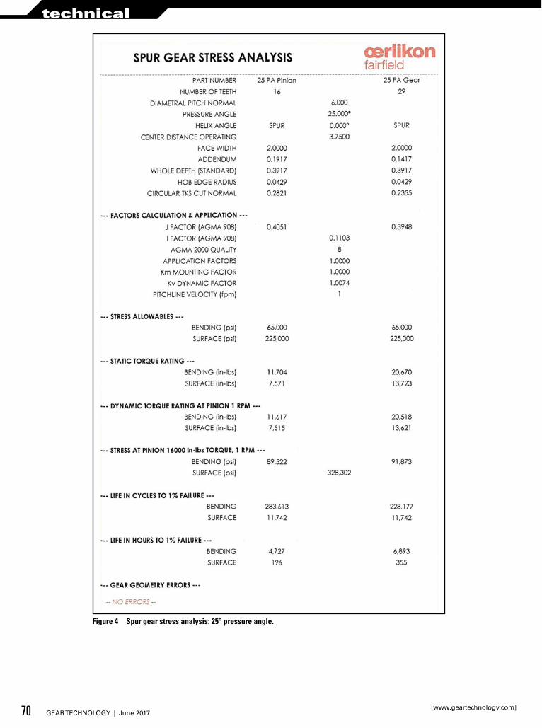
Figure 4 Spur gear stress analysis: 25° pressure angle.
70 GEAR TECHNOLOGY | June 2017[www.geartechnology.com]
technical
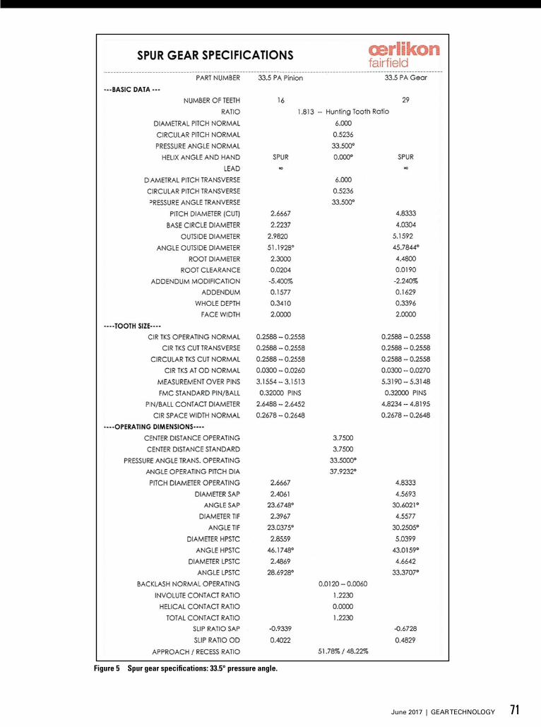
Figure 5 Spur gear specifications: 33.5° pressure angle.
71June 2017 | GEAR TECHNOLOGY

Figure 6 Spur gear stress analysis: 33.5° pressure angle.
72 GEAR TECHNOLOGY | June 2017[www.geartechnology.com]
technical

Figure 7 Spur gear specifications: 35° pressure angle.
73June 2017 | GEAR TECHNOLOGY

Figure 8 Spur gear stress analysis: 35° pressure angle.
74 GEAR TECHNOLOGY | June 2017[www.geartechnology.com]
technical
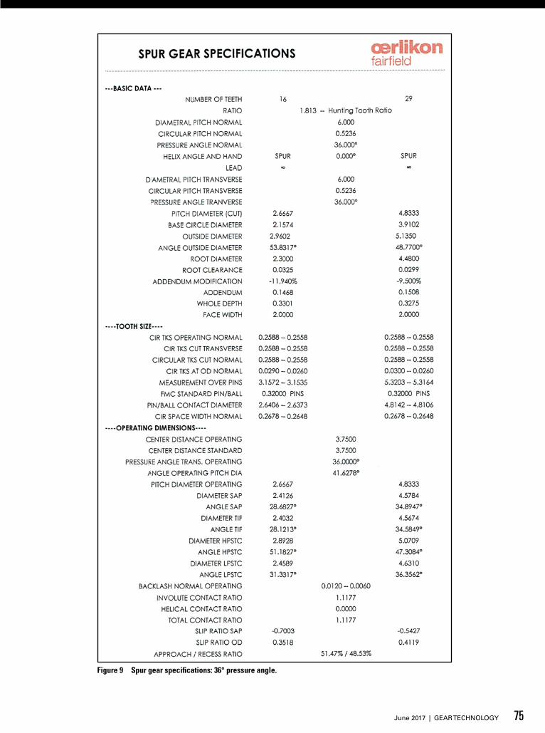
Figure 9 Spur gear specifications: 36° pressure angle.
75June 2017 | GEAR TECHNOLOGY

Figure 10 Spur gear stress analysis: 36° pressure angle.
76 GEAR TECHNOLOGY | June 2017[www.geartechnology.com]
technical
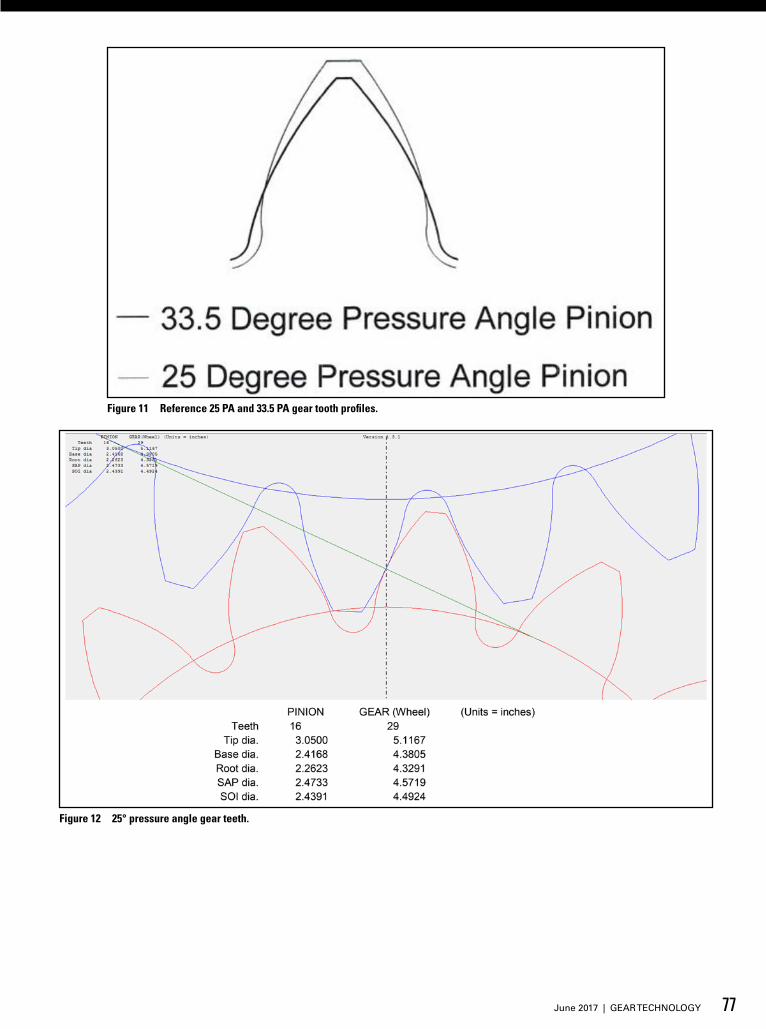
Figure 11 Reference 25 PA and 33.5 PA gear tooth profiles.
Figure 12 25° pressure angle gear teeth.
77June 2017 | GEAR TECHNOLOGY
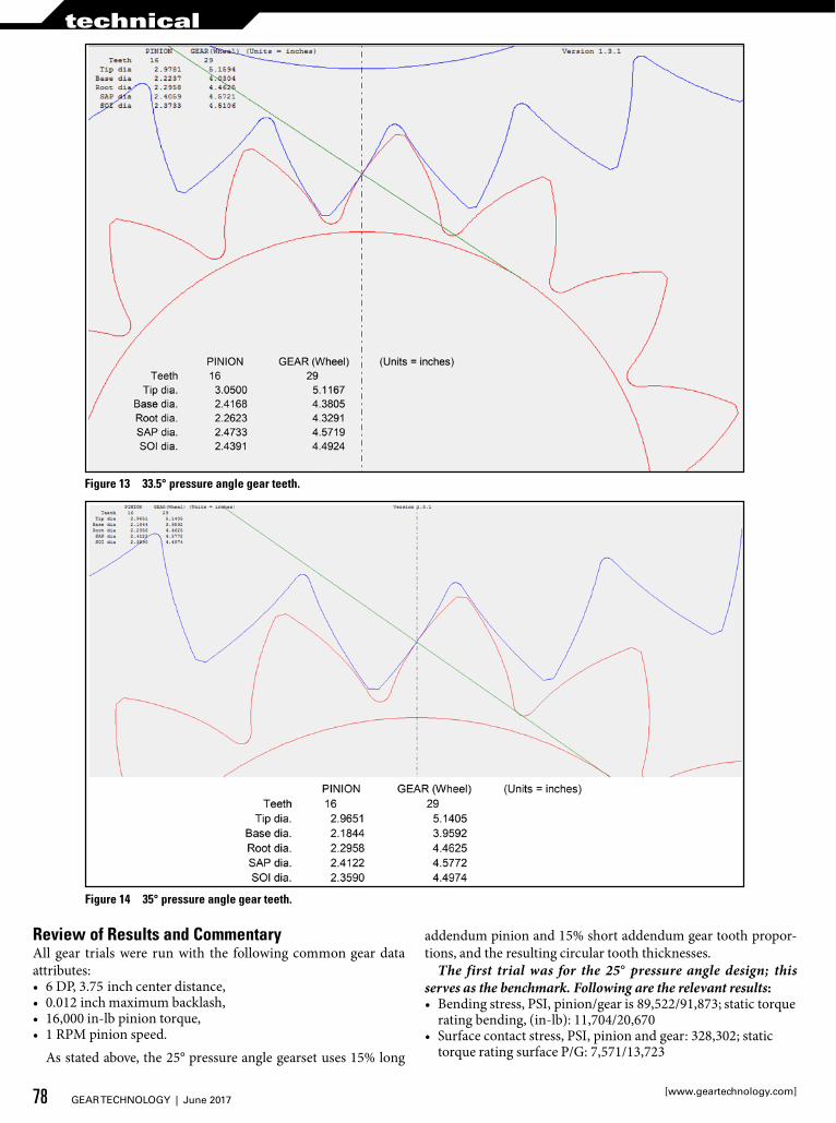
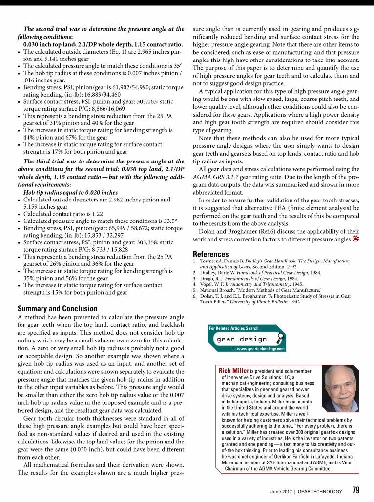
Figure 14 35° pressure angle gear teeth.
Figure 13 33.5° pressure angle gear teeth.
Review of Results and CommentaryAll gear trials were run with the following common gear data attributes:• 6 DP, 3.75 inch center distance,• 0.012 inch maximum backlash,• 16,000 in-lb pinion torque,• 1 RPM pinion speed.
As stated above, the 25° pressure angle gearset uses 15% long
addendum pinion and 15% short addendum gear tooth propor-tions, and the resulting circular tooth thicknesses.
The first trial was for the 25° pressure angle design; this serves as the benchmark. Following are the relevant results:• Bending stress, PSI, pinion/gear is 89,522/91,873; static torque
rating bending, (in-lb): 11,704/20,670• Surface contact stress, PSI, pinion and gear: 328,302; static
torque rating surface P/G: 7,571/13,723
78 GEAR TECHNOLOGY | June 2017[www.geartechnology.com]
technical
Rick Miller is president and sole member of Innovative Drive Solutions LLC, a mechanical engineering consulting business that specializes in gear and geared power drive systems, design and analysis. Based in Indianapolis, Indiana, Miller helps clients in the United States and around the world with his technical expertise. Miller is well-known for helping customers solve their technical problems by successfully adhering to the tenet, “For every problem, there is a solution.” Miller has created over 300 original gearbox designs used in a variety of industries. He is the inventor on two patents granted and one pending — a testimony to his creativity and out-of-the box thinking. Prior to leading his consultancy business he was chief engineer of Oerlikon Fairfield in Lafayette, Indiana. Miller is a member of SAE International and ASME, and is Vice
Chairman of the AGMA Vehicle Gearing Committee.
The second trial was to determine the pressure angle at the following conditions:
0.030 inch top land; 2.1/DP whole depth, 1.15 contact ratio.• The calculated outside diameters (Eq. 1) are 2.965 inches pin-
ion and 5.141 inches gear• The calculated pressure angle to match these conditions is 35°• The hob tip radius at these conditions is 0.007 inches pinion /
.016 inches gear.• Bending stress, PSI, pinion/gear is 61,902/54,990; static torque
rating bending, (in-lb): 16,889/34,460• Surface contact stress, PSI, pinion and gear: 303,063; static
torque rating surface P/G: 8,866/16,069• This represents a bending stress reduction from the 25 PA
gearset of 31% pinion and 40% for the gear• The increase in static torque rating for bending strength is
44% pinion and 67% for the gear• The increase in static torque rating for surface contact
strength is 17% for both pinion and gearThe third trial was to determine the pressure angle at the
above conditions for the second trial: 0.030 top land, 2.1/DP whole depth, 1.15 contact ratio — but with the following addi-tional requirements:
Hob tip radius equal to 0.020 inches• Calculated outside diameters are 2.982 inches pinion and
5.159 inches gear• Calculated contact ratio is 1.22• Calculated pressure angle to match these conditions is 33.5°• Bending stress, PSI, pinion/gear: 65,949 / 58,672; static torque
rating bending, (in-lb): 15,853 / 32,297• Surface contact stress, PSI, pinion and gear: 305,358; static
torque rating surface P/G: 8,733 / 15,828• This represents a bending stress reduction from the 25 PA
gearset of 26% pinion and 36% for the gear• The increase in static torque rating for bending strength is
35% pinion and 56% for the gear• The increase in static torque rating for surface contact
strength is 15% for both pinion and gear
Summary and ConclusionA method has been presented to calculate the pressure angle for gear teeth when the top land, contact ratio, and backlash are specified as inputs. This method does not consider hob tip radius, which may be a small value or even zero for this calcula-tion. A zero or very small hob tip radius is probably not a good or acceptable design. So another example was shown where a given hob tip radius was used as an input, and another set of equations and calculations were shown separately to evaluate the pressure angle that matches the given hob tip radius in addition to the other input variables as before. This pressure angle would be smaller than either the zero hob tip radius value or the 0.007 inch hob tip radius value in the proposed example and is a pre-ferred design, and the resultant gear data was calculated.
Gear tooth circular tooth thicknesses were standard in all of these high pressure angle examples but could have been speci-fied as non-standard values if desired and used in the existing calculations. Likewise, the top land values for the pinion and the gear were the same (0.030 inch), but could have been different from each other.
All mathematical formulas and their derivation were shown. The results for the examples shown are a much higher pres-
sure angle than is currently used in gearing and produces sig-nificantly reduced bending and surface contact stress for the higher pressure angle gearing. Note that there are other items to be considered, such as ease of manufacturing, and that pressure angles this high have other considerations to take into account. The purpose of this paper is to determine and quantify the use of high pressure angles for gear teeth and to calculate them and not to suggest good design practice.
A typical application for this type of high pressure angle gear-ing would be one with slow speed, large, coarse pitch teeth, and lower quality level, although other conditions could also be con-sidered for these gears. Applications where a high power density and high gear tooth strength are required should consider this type of gearing.
Note that these methods can also be used for more typical pressure angle designs where the user simply wants to design gear teeth and gearsets based on top lands, contact ratio and hob tip radius as inputs.
All gear data and stress calculations were performed using the AGMA GRS 3.1.7 gear rating suite. Due to the length of the pro-gram data outputs, the data was summarized and shown in more abbreviated format.
In order to ensure further validation of the gear tooth stresses, it is suggested that alternative FEA (finite element analysis) be performed on the gear teeth and the results of this be compared to the results from the above analysis.
Dolan and Broghamer (Ref. 6) discuss the applicability of their work and stress correction factors to different pressure angles.
References1. Townsend, Dennis B. Dudley’s Gear Handbook: The Design, Manufacture,
and Application of Gears, Second Edition, 1992.2. Dudley, Darle W. Handbook of Practical Gear Design, 1984.3. Drago, R. J. Fundamentals of Gear Design, 1984.4. Vogel, W. F. Involuometry and Trigonometry, 1945.5. National Broach. “Modern Methods of Gear Manufacture.”6. Dolan, T. J. and E.L. Broghamer. “A Photoelastic Study of Stresses in Gear
Tooth Fillets,” University of Illinois Bulletin, 1942.
gear design
For Related Articles Search
at www.geartechnology.com
79June 2017 | GEAR TECHNOLOGY