designing and implementing a level ii high power rocket with dual electronically triggered parachute...
TRANSCRIPT
American Institute of Aeronautics and Astronautics
1
Designing and Implementing a Level II High Power Rocket
with Dual Electronically Triggered Parachute Deployments
Aaron M. Blacker1
Georgia Institute of Technology, Atlanta, GA, 30332
A level II High Power Rocket (HPR) with dual electronically triggered parachute
deployments utilizes two pressurization chambers for separate and strategic recovery
events. Those two events are an apogee-drogue, and low altitude-main, parachute
deployments, both activated by an onboard circuit. Such a rocket also requires a
motor mount sub-assembly that both secures fins which enhance stability and retains
a motor to provide unidirectional thrust. The process of designing and implementing
a rocket of this complexity is an enriching engineering endeavor that requires the
application of theoretical concepts and an ability to foresee future engineering
challenges.
Nomenclature
𝑎 = acceleration
𝐶𝐷 = drag coefficient
𝐶𝐷,0 = zero-lift drag coefficient
𝐶𝑁,𝛼 = normal force coefficient
𝐶𝑁,𝛼,0 = minimum normal force coefficient
𝐷 = drag
𝑑𝑏 = body tube diameter
𝑑𝑚𝑎𝑥 = maximum body tube diameter
𝑑𝑝 = parachute diameter
ℎ = height of deployment pressure chamber
𝑚 = stability margin
𝑀∞ = Mach number
𝑃 = pressure
𝑆 = planform area
𝑥𝑐𝑔 = position of center of gravity along longitudinal (body tube) axis
𝑥𝑐𝑝 = position of CP along longitudinal (body tube) axis
𝑞∞ = freestream dynamic pressure
𝑣𝑡𝑒𝑟𝑚 = terminal velocity
𝑣∞ = freestream velocity
𝑊 = weight
𝜌∞ = freestream density
I. Introduction
ITH an increasingly large envelope of theoretical concepts covered in undergraduate aerospace engineering
curricula, it is important that undergraduate students still gain the necessary hands on engineering experience
to be effective in academia or industry. Building a HPR is one way to practice effective design techniques from
analyzing the scope of a mission, to considering possible vehicle architectures, to building physical hardware that
most accurately matches a computer design. High Power Rocketry (HPTY) has three levels which differentiate from
each other by the allowable motor impulses in each class. Level I rockets fly on motors with impulses between 160-
1 Undergraduate Student, School of Aerospace Engineering, Georgia Institute of Technology, AIAA Student Member
W
American Institute of Aeronautics and Astronautics
2
640 N-s, Level II rockets fly on motors between 640-5,120 N-s, and Level III rockets fly on motors between 5,120-
40,960 N-s. Low Power Rocketry entails motors with impulses below 160 N-s. Each level of HPRs requires a passing
certification flight for a user to be able to fly motors of that certification level in the future. The following paper will
outline methods, processes, and potential considerations in order to successfully design, build, launch, and recover a
Level II HPR with dual electronically triggered parachute deployments.
II. Fundamental Science of High Power Rocketry
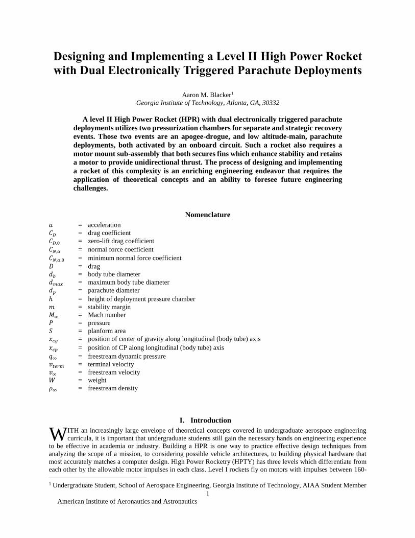
Any HPR design should be based, at the most fundamental level, on the first principles of flight and rocketry.
Since HPRs are often used as test rockets for larger integrated launch vehicles, HPRs should be designed to mimic the
aerodynamic, stability, structural, and propulsion considerations that are being made for the final vehicle.
Figure 1. OpenRocket Design For a Level II HPR.8 Labels indicate components as follows: 1 - inner tube, 2 -
motor, 3 - bottom motor mount centering ring (CR), 4 - fin, 5 - lower body tube and drogue parachute pressure
chamber, 6 - the circuit bay coupler, 7 - main parachute pressure chamber, 8 - secondary coupler which includes a
bulkhead at its bottom (above which is open to the payload bay) 9 - payload bay, 10 - nosecone. Labels 1-4 make up
the motor mount sub-assembly. The centers of pressure and gravity, as well as the stability margin, are noted at the
top right.
A. General Components
In general, a HPR contains a nose cone, payload bay, coupler, and motor mount, plus any recovery components in
the pressure chambers. For the understanding of future concepts in this paper, these components are described here.
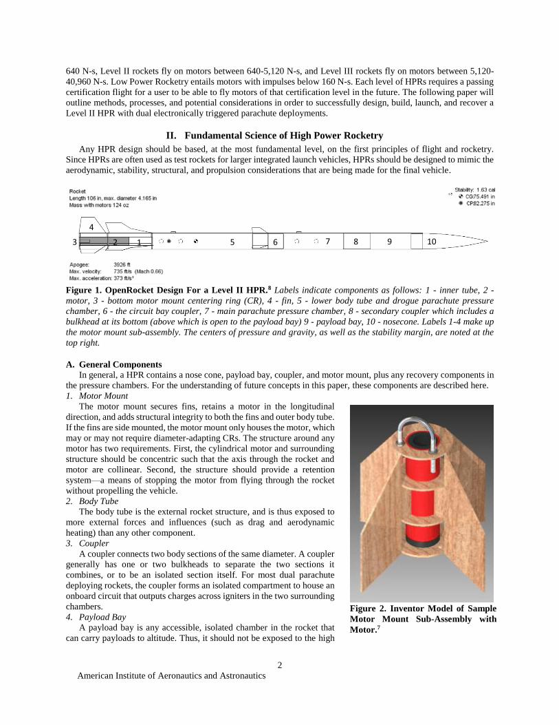
1. Motor Mount
The motor mount secures fins, retains a motor in the longitudinal
direction, and adds structural integrity to both the fins and outer body tube.
If the fins are side mounted, the motor mount only houses the motor, which
may or may not require diameter-adapting CRs. The structure around any
motor has two requirements. First, the cylindrical motor and surrounding
structure should be concentric such that the axis through the rocket and
motor are collinear. Second, the structure should provide a retention
system—a means of stopping the motor from flying through the rocket
without propelling the vehicle.
2. Body Tube
The body tube is the external rocket structure, and is thus exposed to
more external forces and influences (such as drag and aerodynamic
heating) than any other component.
3. Coupler
A coupler connects two body sections of the same diameter. A coupler
generally has one or two bulkheads to separate the two sections it
combines, or to be an isolated section itself. For most dual parachute
deploying rockets, the coupler forms an isolated compartment to house an
onboard circuit that outputs charges across igniters in the two surrounding
chambers.
4. Payload Bay
A payload bay is any accessible, isolated chamber in the rocket that
can carry payloads to altitude. Thus, it should not be exposed to the high
2 3
4
5 6 1
7 8 9 10
Figure 2. Inventor Model of Sample
Motor Mount Sub-Assembly with
Motor.7
American Institute of Aeronautics and Astronautics
3
pressure and temperature gradients created by gunpowder parachute deployment charges.
5. Nosecone
As the first structure exposed to the freestream velocity the nosecone and its aerodynamics for a given flight regime
are essential to establish continuous of flow around the entire body. Various geometries will be introduced later in this
section.
6. Recovery Components
There are a wide range of recovery methods that may be used to provide safe landing speeds, many of which will
be introduced later.
B. Aerodynamics
Aerodynamic drag is one of three forces acting on a rocket (thrust and weight being the others). Drag comes in
five forms. Skin friction drag is a shear stress distribution opposite the direction of motion due to the kinematic
viscosity of air integrated over the surface of the rocket;
pressure or form drag results from the pressure
distribution across the body geometry; wave drag
occurs when sudden, compressive spikes in density
result from supersonic flow; and induced drag, though
unimportant to HPTY, results from lift.1
The relative significance of drag on a rocket is a
function of the flight regime. In low speed flight,
aerodynamic forces are minimal, allowing for light
construction and wall mounted fins. This regime is
mainly pertains to low power rockets. At low speeds,
dimpling is an effective way to smooth the transition
from laminar to turbulent flow. In high speed flight, and
even more so in supersonic flight, the vehicle should
utilize a phenolic, fiberglass, carbon fiber, or Kevlar
airframe that can withstand the pressure forces acting
along the rocket. For compressible flows, drag is given
by
𝐷 = 𝑞∞𝑆𝐶𝐷 =
1
2𝜌𝑣∞
2𝑆𝐶𝐷
(1)
where
𝐶𝐷 = 𝐶𝐷,0
1
√1 − 𝑀∞2
(2)
for subsonic flow and,
𝐶𝐷 = 𝐶𝐷,0
1
√𝑀∞2 − 1
(3)
for supersonic flow.4
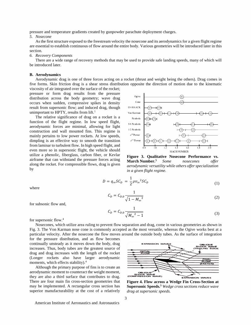
Nosecones, which utilize area ruling to prevent flow separation and drag, come in various geometries as shown in
Fig. 3. The Von Karman nose cone is commonly accepted as the most versatile, whereas the Ogive works best at a
particular velocity. After the nosecone the flow moves around the outside body tubes. As the surface of integration
for the pressure distribution, and as flow becomes
continually unsteady as it moves down the body, drag
increases. Thus, body tubes are the greatest source of
drag and drag increases with the length of the rocket
(Longer rockets also have larger aerodynamic
moments, which effects stability).4
Although the primary purpose of fins is to create an
aerodynamic moment to counteract the weight moment,
they are also a third surface that contributes to drag.
There are four main fin cross-section geometries that
may be implemented. A rectangular cross section has
superior manufacturability at the cost of a relatively
Figure 3. Qualitative Nosecone Performance vs.
March Number.5 Some nosecones offer
aerodynamic versatility while others offer specialization
in a given flight regime.
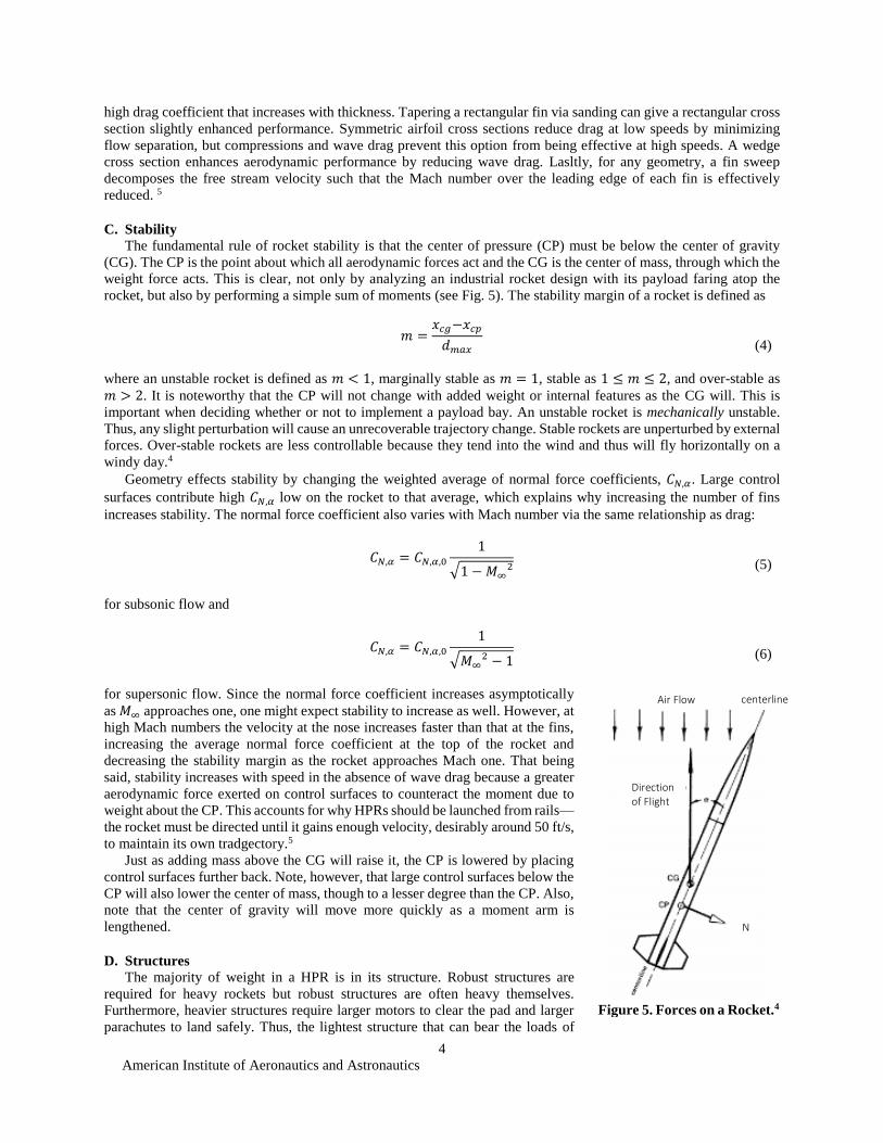
Figure 4. Flow across a Wedge Fin Cross-Section at
Supersonic Speeds.5 Wedge cross sections reduce wave
drag at supersonic speeds.
American Institute of Aeronautics and Astronautics
4
high drag coefficient that increases with thickness. Tapering a rectangular fin via sanding can give a rectangular cross
section slightly enhanced performance. Symmetric airfoil cross sections reduce drag at low speeds by minimizing
flow separation, but compressions and wave drag prevent this option from being effective at high speeds. A wedge
cross section enhances aerodynamic performance by reducing wave drag. Lasltly, for any geometry, a fin sweep
decomposes the free stream velocity such that the Mach number over the leading edge of each fin is effectively
reduced. 5
C. Stability
The fundamental rule of rocket stability is that the center of pressure (CP) must be below the center of gravity
(CG). The CP is the point about which all aerodynamic forces act and the CG is the center of mass, through which the
weight force acts. This is clear, not only by analyzing an industrial rocket design with its payload faring atop the
rocket, but also by performing a simple sum of moments (see Fig. 5). The stability margin of a rocket is defined as
𝑚 =𝑥𝑐𝑔−𝑥𝑐𝑝
𝑑𝑚𝑎𝑥
(4)
where an unstable rocket is defined as 𝑚 < 1, marginally stable as 𝑚 = 1, stable as 1 ≤ 𝑚 ≤ 2, and over-stable as
𝑚 > 2. It is noteworthy that the CP will not change with added weight or internal features as the CG will. This is
important when deciding whether or not to implement a payload bay. An unstable rocket is mechanically unstable.
Thus, any slight perturbation will cause an unrecoverable trajectory change. Stable rockets are unperturbed by external
forces. Over-stable rockets are less controllable because they tend into the wind and thus will fly horizontally on a
windy day.4
Geometry effects stability by changing the weighted average of normal force coefficients, 𝐶𝑁,𝛼. Large control
surfaces contribute high 𝐶𝑁,𝛼 low on the rocket to that average, which explains why increasing the number of fins
increases stability. The normal force coefficient also varies with Mach number via the same relationship as drag:
𝐶𝑁,𝛼 = 𝐶𝑁,𝛼,0
1
√1 − 𝑀∞2
(5)
for subsonic flow and
𝐶𝑁,𝛼 = 𝐶𝑁,𝛼,0
1
√𝑀∞2 − 1
(6)
for supersonic flow. Since the normal force coefficient increases asymptotically
as 𝑀∞ approaches one, one might expect stability to increase as well. However, at
high Mach numbers the velocity at the nose increases faster than that at the fins,
increasing the average normal force coefficient at the top of the rocket and
decreasing the stability margin as the rocket approaches Mach one. That being
said, stability increases with speed in the absence of wave drag because a greater
aerodynamic force exerted on control surfaces to counteract the moment due to
weight about the CP. This accounts for why HPRs should be launched from rails—
the rocket must be directed until it gains enough velocity, desirably around 50 ft/s,
to maintain its own tradgectory.5
Just as adding mass above the CG will raise it, the CP is lowered by placing
control surfaces further back. Note, however, that large control surfaces below the
CP will also lower the center of mass, though to a lesser degree than the CP. Also,
note that the center of gravity will move more quickly as a moment arm is
lengthened.
D. Structures
The majority of weight in a HPR is in its structure. Robust structures are
required for heavy rockets but robust structures are often heavy themselves.
Furthermore, heavier structures require larger motors to clear the pad and larger
parachutes to land safely. Thus, the lightest structure that can bear the loads of
Figure 5. Forces on a Rocket.4
Air Flow
Direction of Flight
N
centerline
American Institute of Aeronautics and Astronautics
5
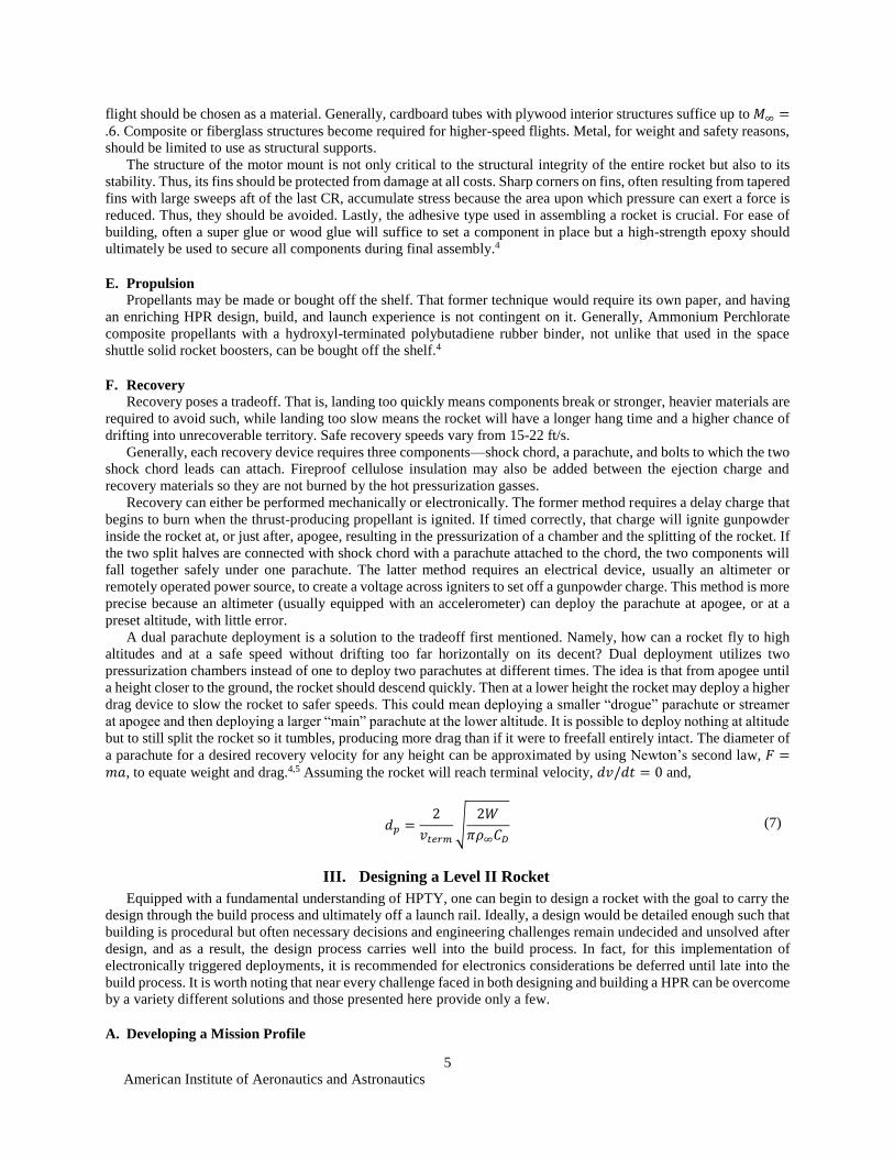
flight should be chosen as a material. Generally, cardboard tubes with plywood interior structures suffice up to 𝑀∞ =.6. Composite or fiberglass structures become required for higher-speed flights. Metal, for weight and safety reasons,
should be limited to use as structural supports.
The structure of the motor mount is not only critical to the structural integrity of the entire rocket but also to its
stability. Thus, its fins should be protected from damage at all costs. Sharp corners on fins, often resulting from tapered
fins with large sweeps aft of the last CR, accumulate stress because the area upon which pressure can exert a force is
reduced. Thus, they should be avoided. Lastly, the adhesive type used in assembling a rocket is crucial. For ease of
building, often a super glue or wood glue will suffice to set a component in place but a high-strength epoxy should
ultimately be used to secure all components during final assembly.4
E. Propulsion
Propellants may be made or bought off the shelf. That former technique would require its own paper, and having
an enriching HPR design, build, and launch experience is not contingent on it. Generally, Ammonium Perchlorate
composite propellants with a hydroxyl-terminated polybutadiene rubber binder, not unlike that used in the space
shuttle solid rocket boosters, can be bought off the shelf.4
F. Recovery
Recovery poses a tradeoff. That is, landing too quickly means components break or stronger, heavier materials are
required to avoid such, while landing too slow means the rocket will have a longer hang time and a higher chance of
drifting into unrecoverable territory. Safe recovery speeds vary from 15-22 ft/s.
Generally, each recovery device requires three components—shock chord, a parachute, and bolts to which the two
shock chord leads can attach. Fireproof cellulose insulation may also be added between the ejection charge and
recovery materials so they are not burned by the hot pressurization gasses.
Recovery can either be performed mechanically or electronically. The former method requires a delay charge that
begins to burn when the thrust-producing propellant is ignited. If timed correctly, that charge will ignite gunpowder
inside the rocket at, or just after, apogee, resulting in the pressurization of a chamber and the splitting of the rocket. If
the two split halves are connected with shock chord with a parachute attached to the chord, the two components will
fall together safely under one parachute. The latter method requires an electrical device, usually an altimeter or
remotely operated power source, to create a voltage across igniters to set off a gunpowder charge. This method is more
precise because an altimeter (usually equipped with an accelerometer) can deploy the parachute at apogee, or at a
preset altitude, with little error.
A dual parachute deployment is a solution to the tradeoff first mentioned. Namely, how can a rocket fly to high
altitudes and at a safe speed without drifting too far horizontally on its decent? Dual deployment utilizes two
pressurization chambers instead of one to deploy two parachutes at different times. The idea is that from apogee until
a height closer to the ground, the rocket should descend quickly. Then at a lower height the rocket may deploy a higher
drag device to slow the rocket to safer speeds. This could mean deploying a smaller “drogue” parachute or streamer
at apogee and then deploying a larger “main” parachute at the lower altitude. It is possible to deploy nothing at altitude
but to still split the rocket so it tumbles, producing more drag than if it were to freefall entirely intact. The diameter of
a parachute for a desired recovery velocity for any height can be approximated by using Newton’s second law, 𝐹 =𝑚𝑎, to equate weight and drag.4,5 Assuming the rocket will reach terminal velocity, 𝑑𝑣/𝑑𝑡 = 0 and,
𝑑𝑝 =2
𝑣𝑡𝑒𝑟𝑚
√2𝑊
𝜋𝜌∞𝐶𝐷
(7)
III. Designing a Level II Rocket
Equipped with a fundamental understanding of HPTY, one can begin to design a rocket with the goal to carry the
design through the build process and ultimately off a launch rail. Ideally, a design would be detailed enough such that
building is procedural but often necessary decisions and engineering challenges remain undecided and unsolved after
design, and as a result, the design process carries well into the build process. In fact, for this implementation of
electronically triggered deployments, it is recommended for electronics considerations be deferred until late into the
build process. It is worth noting that near every challenge faced in both designing and building a HPR can be overcome
by a variety different solutions and those presented here provide only a few.
A. Developing a Mission Profile
American Institute of Aeronautics and Astronautics
6
The complexity of a mission profile effects the intricacy of a design and its implementation. A mission profile can
include requirements as complex as payload deployments altitudes and self-controlled guided recovery, or those as
simple as an apogee target and successful utilization of electronics. We will consider the latter two requirements.
Ultimately, creating mission requirements is a compromising process under inherently limited resources (i.e.
allowable motors have only so high impulse and thrust). If the size of the rocket itself is a mission requirement, the
maximum altitude of the rocket is more limited. If size is unimportant and maximizing apogee is a main concern, then
a motor mount design may be scrapped for wall mounted fins and an outer body tube with the same diameter as the
motor. This would reduce weight, volume, area, drag, and required thrust, all of which would otherwise limit
performance. We will consider the following requirements for our mission: The rocket should 1. Have a height of at
least 8 feet; 2. Attain an apogee of at least 4,000 feet; 3. Use a motor with an impulse range between 640-5,120 N-s
(as prescribed by level II regulations); 4. Use two electronically triggered parachute deployments for successful
recovery; and 5. Be ready to fly again after recovery if dispensable materials, such as insulation and propellant, are
restocked to original condition.
B. Preliminary Design
Preliminary design should be a “pen and paper” process where all of the required components and materials are
hypothesized. The building processes required to implement the design should be considered but not necessarily limit
the envelope of solutions. It is unlikely that a lack of building solutions will limit design solutions to accomplish this
particular mission.
First, the general components and ensuing structure should be outlined. Since the rocket needs to be 8 ft. tall, the
body cannot be the same diameter as the motor, which are at most 2.95 in. for a level II HPR. This would result in an
extremely flimsy rocket if light weight structures are to be used. Thus, we will need a motor mount which expands
the rocket diameter to a reasonable dimension. This diameter can be adjusted in the computer as real time stability
calculations are outputted. For now, a 4 in. diameter body will do. The biggest challenge with this mission profile is
getting an 8 ft. tall rocket to an apogee of 4,000 ft., which suggest that light weight materials will be a requirement.
Thus, if the fins are to be made out of wood, side mounted fins will not provide adequate support. Thus, the motor
mount should have the fins inserted into it such that they are secured internally to the inner tube of the rocket. The
recovery requirement is not a limiting factor since the required bulkheads, circuit, and recovery materials will not add
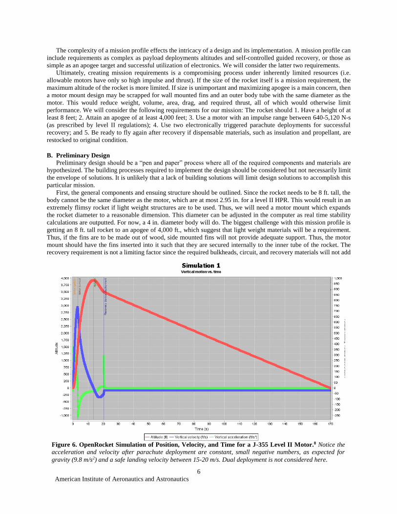
Figure 6. OpenRocket Simulation of Position, Velocity, and Time for a J-355 Level II Motor.8 Notice the
acceleration and velocity after parachute deployment are constant, small negative numbers, as expected for
gravity (9.8 m/s2) and a safe landing velocity between 15-20 m/s. Dual deployment is not considered here.

American Institute of Aeronautics and Astronautics
7
significant weight to the rocket. Since we have 8 ft. of rocket with a constant 4 in. radius, having enough space for
two pressurization chambers that fit parachutes and shock chord, with adequate expansion volumes for the gasses,
should not be an issue. Past experience shows that a payload bay is useful to have as well at the forward end of the
rocket so that if simulations and calculations misrepresent the CG upon loading a motor at the launch, mass may be
added to the top of the rocket to compensate until the intended CG position is re-obtained. As noted before, the CP
will remain constant when internal weight is added. If the circuit is to have access to both pressurization chambers, it
needs to be housed between them in an isolated compartment that will not be exposed to dangerously hot gasses and
high pressures. There is no better place for this compartment than in the coupler. However, note that the coupler has
a smaller diameter than the body tube because it connects two body tubes of the same diameter. Thus, any smaller of
a body diameter may further limit space for the circuit. The coupler should be isolated using wooden bulkheads. The
nosecone selection is unimportant at this point, but we’ll assume a plastic ogive nosecone suffices. The nosecone
material should be reconsidered when the maximum speed is calculated.
C. Computer Design and Simulation
The easiest way to assess the weight, max velocity, apogee, and stability of an HPR in preliminary design is
through the use of a computer program such as OpenRocket. Figure 1 shows the outcome of our preliminary
considerations in the section above. Notice, that canard-type control surfaces were added forward of the CP. This was
an improvised solution to avoid over-stability without dramatic changes in other parameters that fit the mission profile.
Simulating the rocket with different motor configurations is the optimal way to get quick apogee outputs as average
thrust, impulse, weight, and burn-time vary for each motor. The Cissoroni Technology Pro54 J-355 brings the rocket
to 4,000 ft. with a burn time of 3.2 s and average thrust of 355 N. A plot of a flight simulation is shown in Figure 6.7
When it comes to computer simulation, it is important for the user to minimize user error by taking measures such
as adjusting all component materials and sizes. This will enhance the accuracy of ensuing simulations.
D. Detailed Design
Detailed design is the final stage before a prototype can be built. Indeed, this stage combines the stages before and
after it. The detailed design is when the measurements of all the components should be finalized by measuring the
materials themselves. Body tube and inner tube diameters should be measured using digital calipers. The build process
will require any components that need to be cut via computer numerical cutting (CNC) be drawn in a CAD program
that can save drawings as .dxf files. An example of such is shown in Figure 7.
1. Motor Mount
The 2-D drawings that are
imported into a laser cutter
require that their functionality is
fully considered. The bottom
centering of a motor mount is
responsible for motor retention.
One method is to use pipe clamps
that can be secured to the outside
face of the bottom CRs via the
use of t-nuts on the inside face. In
this case holes must be cut
opposite one another about the
inner tube opening. The motor
can also be retained by installing
a removable cap that can be
threaded into place after the
motor is inserted. It is also worth noting that it’s not thrust that directly propels the rocket so much as the normal force
of the rocket casing aft closure exerted on the bottom CR. Without the aft closure the motor would fly through the
rocket alone. The middle CR provides structural support to the outer tube by preventing compression and to the fins
by providing more adhesion area and forcing an extra fin tab to be used. The upper CR should mount a device that
allows the shock chord to hold the bottom booster section of the rocket to the upper section upon parachute
deployment. Fig. 7 shows the three CRs, the top of which has two holes for a U-bolt. The inner tube is the central
piece for the motor mount and is the reason the motor mount exists in the first place. It is responsible for housing the
motor casing and motor during flight. The important dimensional relationships are that the inner CR diameters must
equal the inner tube outer diameter. The outer diameter of the CRs should equal the inner diameter of the body tube
Figure 7. AutoCAD Designs for Motor Mount Components, Coupler, and
Destabilizing Fins.6
American Institute of Aeronautics and Astronautics
8
IV. Build
Entering the build process does not mean that design is over or that all challenges have been overcome. In fact,
designing the circuit assembly will wait until the lower section of the rocket is complete. The build process is critical.
Every cut made and edge filleted with adhesive will contribute error to the overall vehicle. In this stage, Fig. 1 comes
to life.
A. Computer Numerical Cutting
The CRs, fins, and destabilizing canards should be made with CNC techniques. Since we are using wood, a laser
cutter is the best choice. For metal, a CNC waterjet or mill would be better suited. For a Trotec Speedy 300 laser cutter
it is best to set the speed to .6 and the power to 75. If two passes need to be made its important that the wood is not
moved between passes. The most important material and time saving practice is to laser cut a paper towel first to check
that the dimensions from the CAD file transferred to the machine correctly. If so, the next step is to cut one CR. Check
that it fits snug around the inner tube and in the body tube. Now the rest of the CRs will surely fit correctly. The same
precaution should be taken for the fins. The result is the parts in Fig. 8a), which if designed and cut correctly, will be
able to dry-fit together into the their general configuration as shown in Fig. 8b).
B. Motor Mount Assembly
The motor mount is built before anything else. After cutting parts, the components should dry fit together. One
design decision that makes this possible is to have multiple fin tabs—the parts of fins that are internal to the rocket
and sandwiched between two CRs. Multiple fin tabs will also provide more surface area for adhesion to the inner tube
and CRs. The next step is to mount the CRs to the inner tube and the fins to the inner tube and CRs. Best practice is
to set the CRs with wood glue and then to set the fins with wood glue after the CRs are intact. If the CRs are not snug
on the inner tube, all but the bottom CR will require tape that holds them in place as the glue dries. Before the CRs
are mounted three lines are drawn down the inner tube 180° apart. This angle would be 360°/𝑛 if the design had 𝑛
fins. These lines will remain visible as the motor mount is assembled. It is important the CRs are set level, at the height
designated by the open fin joints during the dry fit, to avoid interference when setting the fins. Wood glue should not
be applied between the CRs and inner tube around the three lines where the fins will mount.
The fins should be set individually, along each of the three lines, using tape while the wood glue cures. No fin
should be mounted between the two holes for the U-bolt on the top CR. No fin should interfere with the future
installation of t-nuts on the lower CR. These two considerations should have been made during the dry-fit process.
After the motor mount is locked into place with wood glue, the seams between the fins and/or CRs, and/or inner tube,
many of which already have glue on them, should be locked into place with a slow-curing, high-strength, two
component, epoxy.
C. Body Tube Modification
As shown in figure 8b), fin slots should be cut along the body tube such that openings as thick and long as each
fin will allow the motor mount to slide into the body tube during final assmembly. The cutting lines for each slot
a b c d e
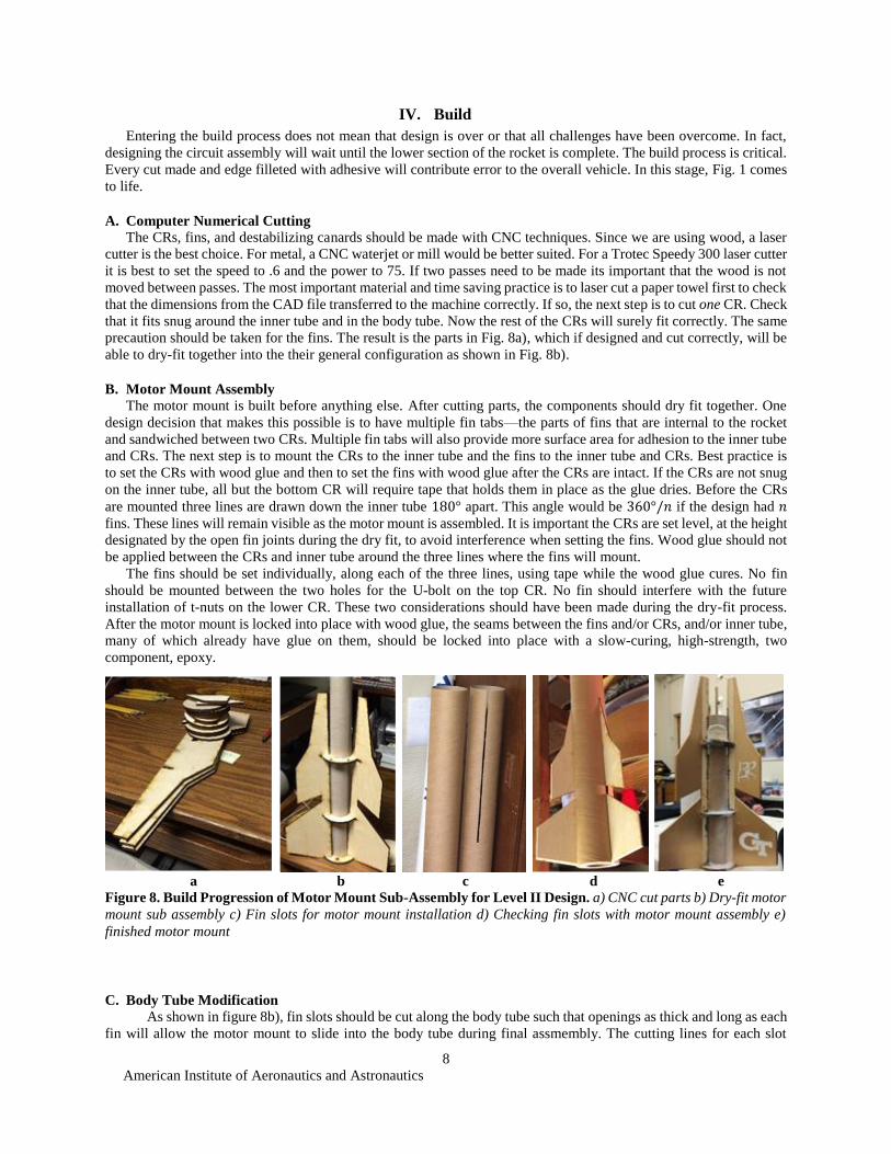
Figure 8. Build Progression of Motor Mount Sub-Assembly for Level II Design. a) CNC cut parts b) Dry-fit motor
mount sub assembly c) Fin slots for motor mount installation d) Checking fin slots with motor mount assembly e)
finished motor mount
American Institute of Aeronautics and Astronautics
9
should be positioned half the thickness of each fin from 180° separated lines around the lower body tube. Cutting may
be done with an exacto knife, or for someone with precise hands, a dremel. The motor mount should then be slid into
the slots as shown in Fig. 8d) to verify the presision of the cuts. The body tubes should also be cut to proper lengths
as indicated in computer design. Recall that the positioning of mass components along the body tube axis should be
implemented as closely to the computer design as possible as to build a rocket with the indicated CP. Creating a rocket
with an incorrect CG is far less important and safe than creating one with an incorrect CG. The CG can always be
adjusted by adding mass to the payload bay.
D. Coupler Assembly
Our design entails that two couplers be made, one to separate the two pressurization chambers and to house the
onboard circuit and another to separate the upper pressurization chamber from the payload bay.
1. Creating a coupler
For a paper-milled body tube of thickness, 𝑡𝑏, a coupler can be produced by removing a fraction of the
circumference from body tube section of the same length as the desired coupler length. The arc length, s, that should
be removed is given by
𝑠 = 2𝜋𝑡𝑏 (9)
The two open ends of the body tube may then be adhered along the inside seam using epoxy. Epoxy should not
be used on the outside of a coupler as to allow the coupler to slide smoothly during deployment.
2. Circuit Assembly and Implementation
There are infinitely many ways to design a circuit assembly for an electronic deployment system but one method
is as follows. The circuit needs to be isolated from deployment charge pressures, removable to access flight data or
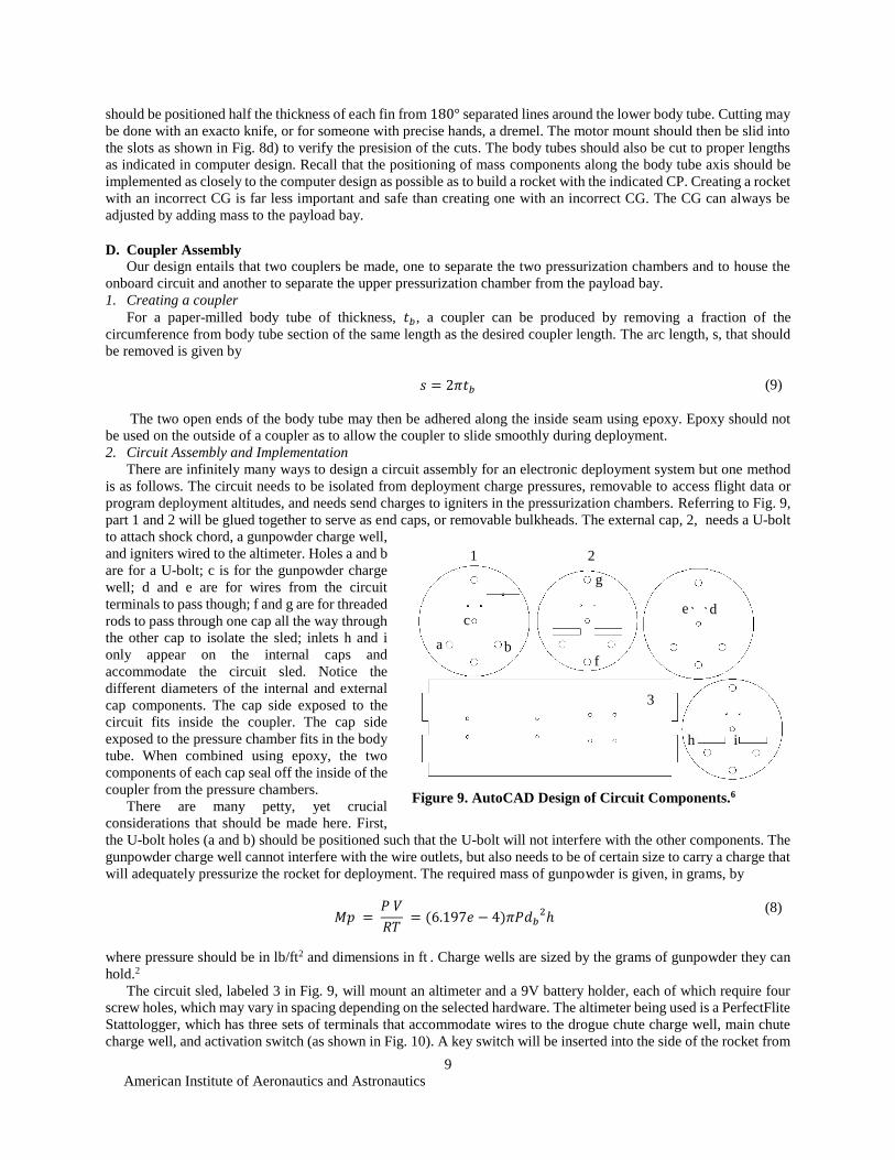
program deployment altitudes, and needs send charges to igniters in the pressurization chambers. Referring to Fig. 9,
part 1 and 2 will be glued together to serve as end caps, or removable bulkheads. The external cap, 2, needs a U-bolt
to attach shock chord, a gunpowder charge well,
and igniters wired to the altimeter. Holes a and b
are for a U-bolt; c is for the gunpowder charge
well; d and e are for wires from the circuit
terminals to pass though; f and g are for threaded
rods to pass through one cap all the way through
the other cap to isolate the sled; inlets h and i
only appear on the internal caps and
accommodate the circuit sled. Notice the
different diameters of the internal and external
cap components. The cap side exposed to the
circuit fits inside the coupler. The cap side
exposed to the pressure chamber fits in the body
tube. When combined using epoxy, the two
components of each cap seal off the inside of the
coupler from the pressure chambers.
There are many petty, yet crucial
considerations that should be made here. First,
the U-bolt holes (a and b) should be positioned such that the U-bolt will not interfere with the other components. The
gunpowder charge well cannot interfere with the wire outlets, but also needs to be of certain size to carry a charge that
will adequately pressurize the rocket for deployment. The required mass of gunpowder is given, in grams, by
𝑀𝑝 =
𝑃 𝑉
𝑅𝑇 = (6.197𝑒 − 4)𝜋𝑃𝑑𝑏
2ℎ
(8)
where pressure should be in lb/ft2 and dimensions in ft . Charge wells are sized by the grams of gunpowder they can
hold.2
The circuit sled, labeled 3 in Fig. 9, will mount an altimeter and a 9V battery holder, each of which require four
screw holes, which may vary in spacing depending on the selected hardware. The altimeter being used is a PerfectFlite
Stattologger, which has three sets of terminals that accommodate wires to the drogue chute charge well, main chute
charge well, and activation switch (as shown in Fig. 10). A key switch will be inserted into the side of the rocket from
Figure 9. AutoCAD Design of Circuit Components.6
a b
c d
f
e
h i
g
1 2
3
American Institute of Aeronautics and Astronautics
10
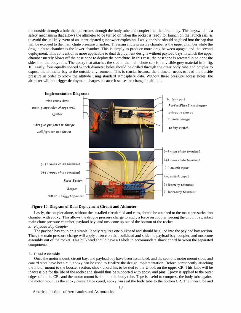
the outside through a hole that penetrates through the body tube and coupler into the circuit bay. This keyswitch is a
safety mechanism that allows the altimeter to be turned on when the rocket is ready for launch on the launch rail, as
to avoid the unlikely event of an unanticipated gunpowder explosion. Lastly, the sled should be glued into the cap that
will be exposed to the main chute pressure chamber. The main chute pressure chamber is the upper chamber while the
drogue chute chamber is the lower chamber. This is simply to produce more drag between apogee and the second
deployment. This convention is more applicable to dual deployment designs without payload bays in which the upper
chamber merely blows off the nose cone to deploy the parachute. In this case, the nosecone is screwed in on opposite
sides into the body tube. The epoxy that attaches the sled to the main chute cap is the visible grey material in in fig.
10. Lastly, four equally spaced ¼ inch diameter holes should be drilled through the outer body tube and coupler to
expose the altimeter bay to the outside environment. This is crucial because the altimeter needs to read the outside
pressure in order to know the altitude using standard atmosphere data. Without these pressure access holes, the
altimeter will not trigger deployment charges because it senses no change in altitude.
Lastly, the coupler alone, without the installed circuit sled and caps, should be attached to the main pressurization
chamber with epoxy. This allows the drogue pressure charge to apply a force on coupler forcing the circuit bay, intact
main chute pressure chamber, payload bay, and nosecone up out of the bottom of the rocket.
3. Payload Bay Coupler
The payload bay coupler is simple. It only requires one bulkhead and should be glued into the payload bay section.
Thus, the main pressure charge will apply a force on that bulkhead and slide the payload bay, coupler, and nosecone
assembly out of the rocket. This bulkhead should have a U-bolt to accommodate shock chord between the separated
components.
E. Final Assembly
Once the motor mount, circuit bay, and payload bay have been assembled, and the sections motor mount slots, and
canard slots have been cut, epoxy can be used to finalize the design implementation. Before permanently attaching
the motor mount to the booster section, shock chord has to be tied to the U-bolt on the upper CR. This knot will be
inaccessible for the life of the rocket and should thus be supported with epoxy and pins. Epoxy is applied to the outer
edges of all the CRs and the motor mount is slid into the body tube. Tape is useful to compress the body tube against
the motor mount as the epoxy cures. Once cured, epoxy can seal the body tube to the bottom CR. The inner tube and
Figure 10. Diagram of Dual Deployment Circuit and Altimeter.

American Institute of Aeronautics and Astronautics
11
bottom CR should also be sealed. A fillet of epoxy should be made using popsicle sticks down the side of each fin
where it meets the body tube wall. If not done already, the couplers should be permanently installed in the correct
body section. Without the nosecone on, each section will have one end sealed and the other exposed.
The final product is show in Fig. 11.
V. Conclusion
Designing a HPR requires a fundamental understanding of flight and the subsequent rocket configurations that
follow this foundation. Design begins once a mission profile is decided upon. If the entire process is to be challenging,
the mission profile will have multiple requirements that are difficult to satisfy simoultaneously. Ultimately, with an
increasingly complex and unique design comes an increasingly beneficial learning experience. Designing and building
a HPR is a process that inherently requires one to overcome tough challenges with compromising solutions, a skill
that extends to all engineering disciplines. The process provides the necessary hands-on experience to transform an
engineering student into an engineer.
Acknowledgments
I would like to give a special thanks to my parents for supporting me in all of my endeavors. I would also like to
thank Joseph Mattingly for introducing me to HPTY.
References
Books 1Anderson, John D. Fundamentals of Aerodynamics. 5th ed. Boston: McGraw-Hill, 2011. Print. Anderson.
Electronic Publications 2Apke, Ted. "Black Powder Usage." Info-central.org. Rocketry Online, n.d. Web. 1 Mar. 2015. 3"HPTY." Rocket.gtorg.gatech.edu. Georgia Tech, Feb. 2015. Web. 25 Feb. 2015.
<http://rocket.gtorg.gatech.edu/files/slides/High_Power_Rocketry.pdf>. 4"Model Rocket Aerodynamics." Rocket.gtorg.gatech.edu. Georgia Tech, Feb. 2015. Web. 1 Mar. 2015.
<http://rocket.gtorg.gatech.edu/files/slides/Model_Rocket_Aerodynamics.pdf>. 5"Scientific Guide to Hobby Rocketry." Rocket.gtorg.gatech.edu. Georgia Tech, Feb. 2015. Web. 20 Feb. 2015.
http://rocket.gtorg.gatech.edu/files/slides/Scientific_Guide_to_Hobby_Rocketry.pdf
Computer Software
6AutoCAD, Autodesk Inc., Software Package, 2014 7Autodesk Inventor Professional, Autodesk Inc., Software Package, 2015 8OpenRocket, Samp Niskanen, Ver. 4.06, 2014
Figure 11. Final Assembly.