designing and building a hybrid (electric/ic) uav
TRANSCRIPT

Bachelor of Engineering
(Mechanical Engineering)
DESIGNING AND BUILDING A HYBRID
(ELECTRIC/IC) UAV
Final Capstone Project Report
By
Ruslan Baitlessov Aitbek Myrzakhmet Kuanysh Sharipov
Principal Supervisor: Desmond Adair
Co-Supervisor: Md Hazrat Ali
April, 2017

ii
DECLARATION
We hereby declare that this report entitled “Designing and building a hybrid (electric/IC)
UAV” is the result of our own project work except for quotations and citations which have
been duly acknowledged. We also declare that it has not been previously or concurrently
submitted for any other degree at Nazarbayev University.
‐‐‐‐‐‐‐‐‐‐‐‐‐‐‐‐‐‐‐‐‐‐‐‐‐‐‐‐‐‐‐‐‐‐‐‐‐‐‐‐‐‐‐
Name: Aitbek Myrzakhmet
Date: 21.04.2017
‐‐‐‐‐‐‐‐‐‐‐‐‐‐‐‐‐‐‐‐‐‐‐‐‐‐‐‐‐‐‐‐‐‐‐‐‐‐‐‐‐‐‐
Name: Kuanysh Sharipov Date: 21.04.2017
‐‐‐‐‐‐‐‐‐‐‐‐‐‐‐‐‐‐‐‐‐‐‐‐‐‐‐‐‐‐‐‐‐‐‐‐‐‐‐‐‐‐‐
Name: Ruslan Baitlessov
Date: 21.04.2017

iii
ACKNOWLEDGEMENT
We would like to express our gratitude to our Capstone Project Supervisors: Professor
Desmond Adair and Professor Md. Hazrat Ali for their trust in us, clear guidance and
valuable feedbacks throughout the work on this project. We also want to thank Professor
Luis Rojas-Solórzano for his help in assisting with performing simulations in Ansys
software. Finally, we give our special thanks to the Capstone Project Coordinator, namely
Professor Konstantinos Kostas for competent management of the overall process.

iv
ABSTRACT
In comparison with conventional internal combustion (IC) engine power trains, a hybrid
electric propulsion system with two or more energy sources has proved to be a more
effective in terms of pollution rate, and a reduction of heat release and sound effects. For
applications of hybrid electric/IC propulsion to vehicles and especially military, it has been
demonstrated that considerable improvement of energy use by reducing fuel consumption
required for basic functions occurs. Due to these factors, the use of unmanned aerial
vehicles (UAVs) may be adopted to civil service as well. This might include detecting and
monitoring disaster, hazards, and environment conditions, and reserving backup power for
emergency. Based on the above information, this Capstone Project aims to develop the
design a prototype of an economical and practical small scale tilt-rotor UAV, with
emphasis on good performance characteristics, including high endurance, a rotor-tilting
mechanism, payload capacity and vertical to horizontal transition stability. The main focus
was on optimizing the aerodynamic parameters of fixed-wing prototype and combining the
hovering abilities of a multi-rotor UAV. The CAD model built in SolidWorks,
computational analysis and simulations of the vehicle performance in Ansys CFX related to
this project are delivered as well. In addition, laboratory work was done in order to check
performance of both the engine and generator.

v
TABLE OF CONTENTS
DECLARATION .................................................................................................................... ii
ACKNOWLEDGEMENT ..................................................................................................... iii
ABSTRACT........................................................................................................................... iv
TABLE OF CONTENTS........................................................................................................ v
LIST OF TABLES ................................................................................................................ vii
LIST OF FIGURES ..............................................................................................................viii
LIST OF ABBREVIATIONS ................................................................................................. x
NOMENCLATURE .............................................................................................................. xi
CHAPTER1. INTRODUCTION ............................................................................................1
1.1. Background ..............................................................................................................1
1.2. Mission .....................................................................................................................3
1.3. Objectives .................................................................................................................3
CHAPTER2. LITERATURE REVIEW .................................................................................6
2.1. Design stages ............................................................................................................6
2.2. Fixed-wing aircraft ...................................................................................................6
2.3. Rotary-wing Aerodynamics .....................................................................................7
2.4. Payload .....................................................................................................................8
2.5. Endurance .................................................................................................................8
2.6. Development of concept...........................................................................................9
CHAPTER3. PRELIMINARY DESIGN..............................................................................11
3.1. Alternative 1 ...........................................................................................................11
3.2. Alternative 2 ...........................................................................................................12
3.3. Alternative 3 ...........................................................................................................13
3.4. Hybrid Propulsion system ......................................................................................14
3.5. Role of tail rotor .....................................................................................................15
3.6. Mass estimation ......................................................................................................16
3.7. Thrust/torque coefficients ......................................................................................17
CHAPTER4. LABORATORY WORK ................................................................................19
vi
4.1. Theoretical background ..........................................................................................19
4.2. Experimental setup .................................................................................................20
4.3. Procedure................................................................................................................22
4.4. Results ....................................................................................................................23
4.5. Conclusion..............................................................................................................23
CHAPTER5. CONTROL SYSTEM .....................................................................................24
5.1. Mathematical modeling ..........................................................................................24
5.2. Avionics .................................................................................................................28
5.3. PID Controller ........................................................................................................29
5.4. Control strategy ......................................................................................................29
CHAPTER6. DETAILED DESIGN .....................................................................................32
6.1. Motor/ESC and propeller selection ........................................................................32
6.2. IC and Generator/Starter ........................................................................................33
6.3. Airfoil and Wing Design ........................................................................................34
6.3.1. Airfoil geometry..............................................................................................34
6.3.2. Airfoil design ..................................................................................................34
6.3.3. Wingspan ........................................................................................................36
6.3.4. Airfoil Simulation ...........................................................................................36
6.4. Stabilizer Simulation ..............................................................................................38
6.5. Fuselage Simulation ...............................................................................................39
6.6. Battery ....................................................................................................................40
6.7. Servo motor ............................................................................................................42
6.8. 3D view of the design model..................................................................................43
6.9. Manufacturing ........................................................................................................43
CHAPTER7. CONCLUSION ...............................................................................................45
REFERENCES .....................................................................................................................46
APPENDICES ......................................................................................................................49
Appendix A. Experiment related material.........................................................................49
Appendix B. Mathematical modeling ...............................................................................53
Appendix C. 3D modeling design .....................................................................................55

vii
LIST OF TABLES
Table 1.1. Classification of UAV by altitude, range and endurance ......................................2
Table 1.2. Design requirements ..............................................................................................5
Table 2.1. Mission and aircraft design requirements for UAV built in US Air Force Institute
of Technology .........................................................................................................................9
Table 2.2. The characteristics of reference UAVs ................................................................10
Table 3.1. Mass estimation of the model ..............................................................................16
Table 3.2. U8 pro KV170 motor specifications ....................................................................17
Table 3.3. U10 KV80 motor specifications ..........................................................................18
Table 4.1. List of parts needed for the experiment ...............................................................20
Table 5.1. State variables for motion model .........................................................................27
Table 5.2. Input variables for motion model.........................................................................27
Table 6.1. Performance of the T-motor U8 pro 170KV with 29*9.5CF propeller ..............32
Table 6.2. Performance of the T-motor U8 pro 170KVwith 22*6 wood propeller ..............33
Table 6.3. Airfoil characteristics at Re=200 000 ..................................................................35
Table 6.4. Values for calculation of a chord length ..............................................................36
Table 6.5. Results of the simulation of S1223 wing for different parameters ......................37
Table 6.6. NACA0012 Stabilizer characteristics ..................................................................39
Table 6.7. Fuselage characteristics .......................................................................................39
Table 6.8. UAV total drag and total lift characteristics ........................................................40

viii
LIST OF FIGURES
Figure 1.1. Different types of UAV according to classification ............................................1
Figure 1.2. Mission profile......................................................................................................3
Figure 2.1. Forces acting on a plane ......................................................................................7
Figure 2.2. Normal induced flow velocities along the blade span during hovering flight: a)
Induced flow, c) velocity distribution along the blade. Rotor blade angles: b) AOA d) angle
of Incidence ............................................................................................................................8
Figure 3.1. Quad-rotor UAV concept ..................................................................................11
Figure 3.2. Schematic view of the propellers quad-rotor concept model ........................11
Figure 3.3. Alternative 2 Design ...........................................................................................12
Figure 3.4. Alternative 3 Design ...........................................................................................13
Figure 3.5. Propeller guard ..................................................................................................13
Figure 3.6. Series propulsion system ....................................................................................14
Figure 3.7. Parallel propulsion system..................................................................................14
Figure 3.8. Pitch, roll and yaw in an aircraft .......................................................................15
Figure 3.9. Control surfaces: red, for yaw; blue, on the tail and on the wings, are for
pitching and rolling respectively ..........................................................................................15
Figure 3.10. View of the aircraft with rotor tilt: a) Rear view, b) Top view ........................16
Figure 3.11. Rear side view of the aircraft with lift forces on wings ...................................16
Figure 3.12. Thrust coefficient vs speed ...............................................................................18
Figure 3.13. Torque coefficient vs rotational speed .............................................................18
Figure 4.1. Diagram of a simple alternator ...........................................................................19
Figure 4.2. Detailed schematic of the laboratory setup ........................................................21
Figure 4.3. Stand for motor and engine connection ..............................................................22
Figure 5.1. Configuration of the UAV model with reference and body frames ...................24
Figure 5.2. A feedback control loop ....................................................................................28
Figure 5.3. A block diagram of PID controller ....................................................................29
Figure 5.4. UAV Control Strategies for (a) Altitude (b) Roll (c) Pitch (d) Yaw ............30
Figure 6.1. Basic parameters of an airfoil . ...........................................................................34
Figure 6.2. S1223 airfoil geometry ......................................................................................35

ix
Figure 6.3. Dependence of lift/drag coefficients on angle of attack for S1223 airfoil .........35
Figure 6.4. Mesh Verification, a) wind tunnel, b) and c) mesh around airfoil, d) mesh near
the boundary layer.................................................................................................................37
Figure 6.5. Velocity distribution for the S1223 wing ...........................................................38
Figure 6.6. Pressure contour for the S1223 wing..................................................................38
Figure 6.7. NACA0012 Airfoil geometry ............................................................................38
Figure 6.8. Velocity distribution for the fuselage .................................................................39
Figure 6.9. Pressure contour for the fuselage .......................................................................40
Figure 6.10. Graph of the efficiency of the S3508 motor ....................................................41
Figure 6.11. Graph of the efficiency of the U8 motor with extrapolated data for 44.4 V ....41
Figure 6.12. Tilting mechanism for the rotor........................................................................42
Figure 6.13. 3D model of the propeller tilt mechanism ........................................................43
Figure 6.14. 3D model of the UAV final design...................................................................43
Figure 6.15. Wing skeleton .................................................................................................434
Figure 6.16. Hot-wired foam blocks shaping......................................................................434
Figure A1. IC engine and DC motor connection ..................................................................52
Figure A2. 3-phase rectifier connection................................................................................52
Figure A3. Resistors on breadboard......................................................................................43
Figure A4. Ignition and tachometer wiring...........................................................................43
Figure C1. CAD drawing ......................................................................................................55
Figure C2. Wing specifications.............................................................................................56
Figure C3. Horizontal flight ..................................................................................................56
Figure C4. Rear tilt rotor mechanism ...................................................................................56
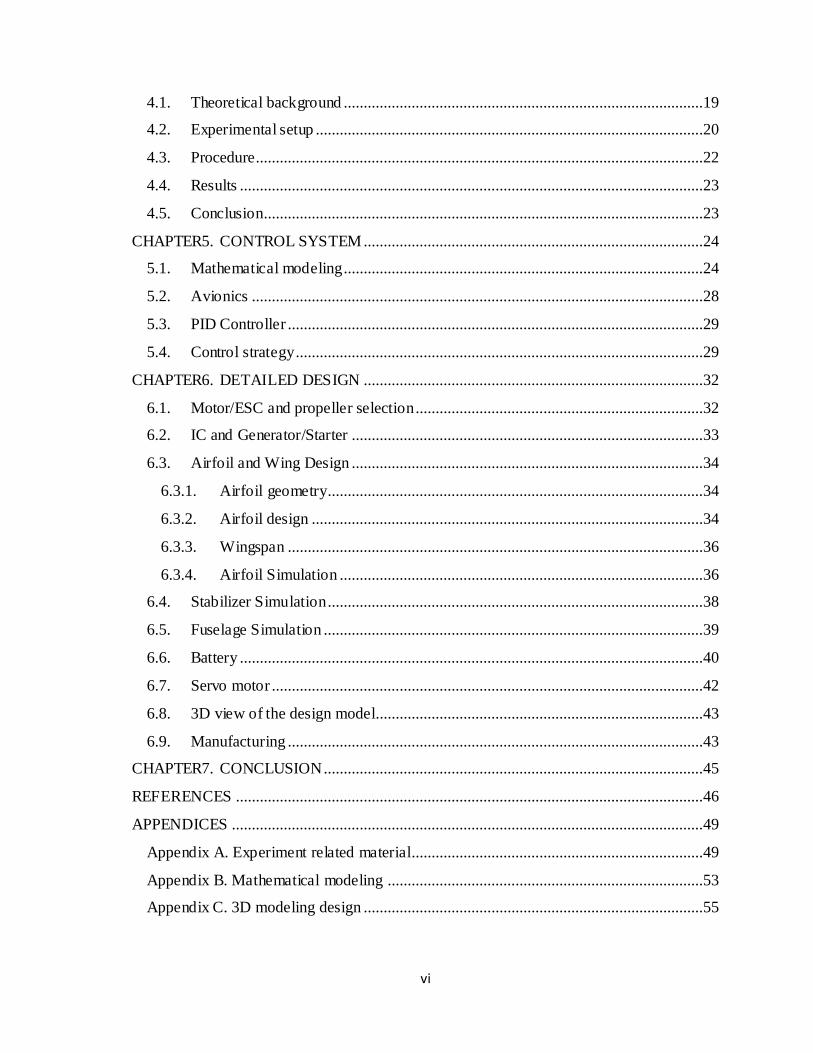
Figure C5. Rendered view of the model ...............................................................................57
Figure C6. VTOL regime......................................................................................................57
Figure C7. Front tilt rotor mechanism ..................................................................................57

x
LIST OF ABBREVIATIONS
AEW Airborne Early Warning
AUM All-up-mass
DOD Department of Defense
DOF Degree of Freedom
IC Internal Combustion
UAV Unmanned Aerial Vehicle
VTOL Vertical Take-Off and Landing

xi
NOMENCLATURE
Ω𝑖 Rotational speed of rotor
𝑏𝑖 Thrust coefficient
𝑘𝑖 Torque coefficient
𝑈𝑜𝑢𝑡 Voltage output from generator
𝐾 Angular speed constant
𝜔𝑚 Angular speed of motor
𝑃𝑜𝑢𝑡 Power output
𝑅𝑚 Resistance of motor
R Rotation matrix from coordinate system 𝑆𝑏 to 𝑆𝑓
𝐩𝒇 Position of UAV in 𝑺𝒇
𝐯𝒃 Linear velocity vector presented in 𝑺𝒃
Diagonal matrix 𝐝𝐢𝐚𝐠(𝒎)
𝐠𝒇 Vector of acceleration of gravity in 𝑺𝒇
𝛚 Angular velocity vector
𝚯 Vector of Euler angles
I Inertial matrix of UAV
𝑭𝑨,𝑻𝒃 Vector of external force in coordinate 𝑬𝒃
𝑭𝑨𝒃 Vector of external aerodynamic force in coordinate 𝑬𝒃
𝑭𝑻𝒃 Vector of thrusts in coordinate 𝑬𝒃
𝚪𝑨,𝑻 external torque vector
𝚪𝑨 External aerodynamics torque vector
𝚪𝑻 External thrust torque vector
𝑱(𝚯) Jacobian matrix
𝑇1 Thrust of the 1st motor
𝑇2 Thrust of the 2nd motor
𝑇3 Thrust of the 3rd motor
𝛿 Tilting angle of the1st and the 2nd motors

xii
𝜉 Tilting angle of the 3rd motor
𝑄1 Torque of the1st motor
𝑄2 Torque of the 2nd motor
𝑄3 Torque of the 3rd motor
𝐷𝑡𝑏 Drag of stabilizer
𝐷𝑤𝑏 Drag of wing
𝐿𝑤𝑏 Lift of wing
𝐿𝑡𝑏 Lift of stabilizer
e Efficiency
𝑻𝒄𝒓𝒖𝒊𝒔𝒆 Thrust during cruise
𝐹𝐿 Lift force
𝐶𝐿 Lift coefficient
𝐴 Area of wing
𝜌 Density of air
𝑣 Velocity of UAV
𝑐 Chord length of wing
𝐿 Wingspan
𝑇𝑐𝑟𝑢𝑖𝑠𝑒𝑝𝑒𝑟𝑚𝑜𝑡𝑜𝑟 Thrust per motor during cruise
𝐶 Capacity of battery
𝑃𝑡𝑜𝑡𝑎𝑙,𝑐𝑟𝑢𝑖𝑠𝑒 Total cruise power usage
𝑒𝑏𝑎𝑡𝑡𝑒𝑟𝑦 Efficiency of battery capacity
𝑒𝑢𝑠𝑎𝑔𝑒 Efficiency of battery usage
V Voltage of battery
Ah Current usage in battery
x State variables
a Input variables
t Time

1
CHAPTER1. INTRODUCTION
1.1. Background
According to the U.S. Department of Defense (DOD) an unmanned aerial vehicle (UAV) is
defined as “A powered vehicle that does not carry a human operator, can be operated
autonomously or remotely, can be expendable or recoverable, and can carry a lethal or
nonlethal payload”. General attributes of UAV are the following:
Smaller size potential;
High versatility;
Greater performance than manned aircraft—design flexibility [5].
Figure 1.1. Different types of UAV according to classification [18]
Before looking into the characteristics of UAV in more detail, it is important to list
common uses of these vehicles. The uses can be classified as follows:
Military uses Civilian uses
Relaying radio signals; Aerial photography;
Protection of ports from offshore attack; Crop monitoring and spraying;
Target designation and monitoring; Pollution and land monitoring;
Radar system jamming and destruction; Fire detection, incident control [7]
Airfield damage assessment;

2
There is a large number of features and characteristics that have been used to classify
UAVs, including maximum take-off mass, operating conditions, capabilities, endurance or
any combination of these and other characteristics. Table1.1 provides a comprehensive
classification of UAV, where both a wide variety of UAV systems and capabilities as well
as multiple ways of differentiation [9].
Table 1.1. Classification of UAV by altitude, range and endurance
Category Mass [kg] Range [km] Flight Altitude [m] Endurance [h]
Micro <5 <10 250 1
Mini <20/25/30/150 <10 150/250/300 <2
Close Range (CR) 25-150 10-30 3000 2-4
Short Range (SR) 50-250 30-70 3000 3-6
Medium Range (MR) 150-500 70-200 5000 6-10
MR Endurance (MRE) 500-1500 >500 8000 10-18
Low altitude deep
penetration (LADP)
250–2500 >250 50–9000 0.5–1
Low altitude long
endurance (LALE)
15–25 >500 3 000 >24
Medium altitude long
endurance (MALE)
1000–1500 >500 3000 24–48
During the last two or three decades UAVs have experienced great development. Currently,
two types of small UAV platforms dominate, namely fixed-wing conventional aircraft and
rotary-wing Vertical Take-Off and Landing (VTOL) aircraft. There is a certain amount of
inherent limitations associated with each type of UAV, such as flexibility, payload,
endurance, and etc. However, the development of a fixed-wing VTOL UAV or so-called
hybrid UAV, which can adopt both the ability of vertical take-off and landing as well as
high cruising speed and enhanced endurance, and the ability to loiter, is a new promising
trend that is taking place. Thus, the possibility of performing either wider range of missions
or a better performance in the same missions becomes possible [24].
Due to the ability of such a hybrid UAV to act like either a fixed wing or rotary wing UAV,
makes the use of such an aircraft very desirable in different missions despite its increased
mechanical complexity and more difficult control features. Tilt-rotor UAVs are considered

3
as one of the most attractive and effective solutions because of their stability, energy
efficiency and controllability [7].
1.2. Mission
A small UAV offers advantages, such as low cost for the airframe itself, low acoustic,
visual and even the heat signatures for military purposes. Particularly, the latter one implies
use of the UAV for land monitoring. The UAV will be advantageously used for aerial
surveillance, with certain missions requiring no detection of the aircraft. It might include
the following tasks, such as detecting and monitoring disaster, hazards, and environment
conditions, and reserving backup power for emergency.
An aircraft mission usually consists of several flight phases with different requirements,
such as take-off and climb, the cruise flight to and from the surveillance area, loitering
(which may include descent and climb) and finally descent and landing. Generally, the
mission profile for this UAV model is shown in the Figure below.
Figure 1.2. Mission profile
1.3. Objectives
Objectives of this project are based on requirements set by a mission of the UAV. An
electric propulsion system itself would be the best choice for this objective, but such a
choice strongly limits the endurance and range due to the low specific energy. Therefore,
combination of electric with IC engine system is required [17].

4
An electric UAV has already been designed within the School of Engineering, Nazarbayev
University, and the object of this further work is to investigate the feasibility of building on
the skills and knowledge already researched and designing a similar UAV, which will have
a much higher endurance capability, and a low acoustic/visual/heat signature. Despite the
versatility of a helicopter in switching between several flights modes, its range and
endurance is much less due to low energy conversion efficiency rotors and supersonic
speed limitations at rotor tips for high cruise speeds. VTOL UAVs do not have these
restrictions for forward flight, and also, providing the propeller radius is not large, the
mechanical designs are usually simple [17].
In summary, the main objectives of this project are to design a prototype of an economical
and practical small scale tilt-rotor UAV, with emphasis on good performance
characteristics that are listed below. These include:
Endurance
Rotor tilting mechanism
Payload capacity
Vertical to horizontal transition stability
Ease of repair and maintenance
Since the project aims to provide a design of a UAV with good performance, the main
focus will be on improving performance by optimizing the aerodynamic parameters of the
fixed-wing prototype and combining the hovering abilities of a multi-rotor UAV. Based on
findings of the preliminary literature review and discussion with the experts, the realistic
and challenging design requirements were defined (Table 1.2). Particularly, the 2nd chapter
will contain information on these findings.

5
Table 1.2. Design requirements Payload Up to 900 g. This value includes the mass of the camera and a lightweight gimbal.
Endurance 1.5 hours. The endurance has to be somewhere between 1 and 2 hours, being
comparable with typical fixed-wing UAVs with hybrid propulsion system
Wingspan 2-2.5 m. The span of the UAV should be appropriate for convenient transportation
and allow its exploration in urban areas.
Mass Up to 10 kg
Operating altitude 100-300 m
Durability and
reliability
To be able to operate in severe weather conditions and to withstand wind gusts.
Flight regime To be able to operate in both RC and autonomous waypoint navigation regimes.

6
CHAPTER2. LITERATURE REVIEW
2.1. Design stages
According to [4], the design of a UAV will usually consist of three stages:
1) Development of concept
Conceptualization is a phase of brainstorming ideas and analysis of advantages and
disadvantages of implementing those ideas. In this part, potential solutions must be
presented for existing problems. Morphological analysis technique includes specific design
parameters listed in a table and various solutions for each problem. Finally, different
alternatives will be evaluated between each other to identify possible strengths and
weakness [27].
2) Preliminary design
Preliminary design includes different alternatives for overall system configuration, which
includes sketches, schematics, diagrams and layouts of the project. During this phase
parameters of created parts are concentrated on the overall framework of the model.
However, it is not sufficient for the final model [20].
3) Detailed design
Detailed design stage includes each aspect of the product and its complete description,
which include CAD models, simulations, drawings, final characteristics and calculations
[10].
There are other phases after the detailed design stage which include manufacturability
factors and modifications followed by continued improvements of the UAV. This report is
concentrated on the preliminary three stages mentioned above.
2.2. Fixed-wing aircraft
During a flight, a fixed-wing aircraft is subjected to basic forces like thrust, drag, weight
and lift. The primary goal of fixed-wing aircraft is to create enough lift for takeoff and

7
landing as well as to provide sufficient lift to remain at a constant altitude during the cruise.
The reaction force (the vertical component of the lift force) is in the opposite direction and
opposes the gravitational force.
The Figure2.1 represents an aircraft travelling with some velocity in a horizontal direction.
A difference of aerodynamic pressures between the upper (suction) and lower (pressure)
surfaces of the aircraft’s wings is a key to providing lift. Specifically, the lower pressure on
the upper surface and the higher pressure on the lower surface of a wing create the reaction
force (lift). In order to create sufficient lift there must be enough thrust to overcome a drag.
This drag consists of two components, namely skin friction and pressure difference
between rear and front sides of the wing. Its impact with a small horizontal component of
thrust resists the motion of the aircraft. Thus, minimization of the drag has a crucial role for
fixed-wing UAV to increase its efficiency [12].
Figure 2.1. Forces acting on a plane [26]
2.3. Rotary-wing Aerodynamics
The rotary-wing aircraft aerodynamics is more complex than that of the fixed-wing one.
The method of achieving lift force on rotary wings is basically the same as for the fixed-
wing. The main difference is ability for the vertical take-off and landing of the rotary-wing
aircraft.
In a rotary-wing system lift is produced by angle of incidence and angle of attack (figure
2.2). Angle of incidence located between chord line of a blade and the rotor hub. Angle of
attack (AOA) located between airfoil chord line and resultant relative wind. Figure2.2
illustrates velocity distribution of along the blades.

8
Figure 2.2. Normal induced flow velocities along the blade span during hovering flight: a)
Induced flow, c) velocity distribution along the blade. Rotor blade angles: b) AOA d) angle
of Incidence [13]
2.4. Payload
Besides the size and mass, the maximum payload and its extra requirement for energy
define the primary layout, size and all-up-mass (AUM) of the UAV. The payload is
important as it is connected with main reasons for construction and designing of the UAV.
Depending on the purpose payloads can be varied from a kilogram up to thousand
kilograms and from a few cubic centimeters to more than a cubic meter in volume. Also,
position of the payload is important, since it has significant influence on the configuration
and model of the UAV frame. In our case, placement of an imaging camera should be in
such a way that it would have the best view of the landscape. Payloads must be placed
around the center of mass of the UAV.
2.5. Endurance
The endurance of the UAV, depending on the requirements, can vary from 1 hour to more
than 24 hours for a long-range surveillance or airborne early warning (AEW) system.
Hence, the volume and mass of the fuel or battery load are strongly related to the endurance
and efficiency of the aircraft aerodynamics. Thus, the mass of fuel can range between 10%
and 50% of UAV’s AUM, depending on its mission, which has a directly connected

9
influence on the endurance. Therefore, amount of fuel should be taken into consideration
during design in order to fit the required endurance.
2.6. Development of concept
In order to create a reference point for the initial calculations, the characteristics of UAV
have to be set. This was done by studying different existing small-scale UAVs designed for
civilian missions. According to [24], there is only one prototype of UAV with a hybrid IC
engine and electric propulsion system built at the US Air Force Institute of Technology.
Despite the fact that several university projects treated the design/construction of hybrid-
electric propulsion systems there appears to be no information about design requirements or
characteristics of their UAVs. Table2.1 below gives design requirements for UAV
mentioned above.
Table 2.1. Mission and aircraft design requirements for UAV built in US Air Force Institute
of Technology
Parameter Value Units
Endurance (tendur) 3 hr
One way cruise time (tcruise) 1 hr
Cruise velocity (Vcruise) 20.5 m/s
Max velocity (Vmax) 30.9 m/s
Rate of climb (ROC) 2.03 m/s
Take-off altitude MSL (hTO) 1500 m
Mission altitude AGL (h) 300 m
Max gross takeoff mass (mTO) 13.6 kg
Payload mass (mpay) 2.27 kg
Payload power (Ppay) 25 W
Flight control system power (PFCS) 10 W
Zero-lift drag coefficient (CD.O) 0.036
Oswald span efficiency factor (e) 0.85
In order to identify a reference UAV with certain characteristics, the examples of current
small UAVs have to be analyzed. Table2.2 illustrates some existing models with either an
electric motor or IC engine propulsion system [19]. As can be seen from this table, smaller

10
UAVs generally have an electric propulsion system with limited flight time, while IC-
powered UAVs have longer endurance, but higher take-off mass.
Table 2.2. The characteristics of reference UAVs
Model name Company Power plant Weight, lbs Span, inches Endurance,
min
Raven B AeroVironment, Inc. Electric motor 4.2 53 90
Puma AeroVironment, Inc. Electric motor 13 102 150
Stalker Lockheed Martin Electric motor 14 120 120
Desert Hawk
IIII
Lockheed Martin Electric motor 6.5 54 90
Silver Fox Advanced Ceramics
Research
Gas engine 26.2 94 600
Scan Eagle Boeing Gas engine 39.6 120 900
As it can be seen from the Table 2.2, a wing span ranges between 53 and 120 inches or
1.35-3 m, whereas a weight of 4.2-39.6 lbs or 1.89-17.8 kg gives a reference point for
initial sizing and weight calculations. Regarding the endurance, its value for a hybrid UAV
can fluctuate between 90 and 900 min.

11
CHAPTER3. PRELIMINARY DESIGN
3.1. Alternative 1
An initial concept of the small-scale UAV was chosen to be a multi-copter (Figures3.1-
3.2.), particularly quad-rotor. The main reasons for using this arrangement rather than a tri-
copter are:
simplicity (a quad-rotor looks like a simple cross with four identical motors),
control system (quad-rotors are symmetrical, therefore a simpler control setup is
required), and
reliability (due to their mechanical simplicity, quadrotors could withstand a crash
much better than tri-copters).
Figure 3.1. Quad-rotor UAV concept [23]
Figure 3.2. Schematic view of the propellers quad-rotor concept model [23]
However, there are several limitations associated with quad-rotor UAVs in comparison
with VTOL UAVs. The former involve greater mechanical and electronic complexity,
which in turn leads to more complicated maintenance and repair processes. Thereby, the
user’s operational endurance will be decreased, which can cause an increase in operational
costs. Due to lower speeds and shorter flight ranges for multi-copter UAVs, some
additional flights for surveying certain significant areas are required, and thus increase in
time and operational costs take place [23].

12
3.2. Alternative 2
The first alternative is inefficient and not suitable for long-distance deployment for our
purposes and characteristics. It was therefore decided to investigate the alternative shown in
Figure3.3. This consists of a fuselage, 3 propellers, 3 motors, clutch, controllers, etc. Due to
limits on the mass of the prototype, flight time and maximum altitude, and to provide
stability, and, rolling, yawing and pitching capability, the number of motors was chosen to
be 3. In order to decrease the noise generated due to motors, 2 motors located ahead of the
wings can be switched from IC engine at the take-off to battery powered during cruise and
loitering. During cruise these two motors plus related propellers have to tilt by 90 degrees
so that a horizontal driving thrust is applied.
Figure 3.3. Alternative 2 Design
According to the objectives of the UAV’s concept, it should be VTOL. During takeoff all
three motors are vectored as illustrated in the Figure3.3 in order to have enough vertical
thrust to overcome the aircraft’s weight and prove a small vertical acceleration; in addition
to providing stability. This second alternative has however several disadvantages with
efficiency and for our UAV this is highly significant, as this influences the endurance.
Considering this design, the propeller rotates above the wing of the aircraft and around 40%
of its area is above the wing. Also, the width of wing is approximately 10 inch according
the size of our UAV. Analyzing the aerodynamics, it can be clear that a propeller above the
wing has less effective thrust since it creates an additional vertical drag on the surface of
the wing by the air flow downwards. This is the case for the two front propellers.
Therefore, this design is considered as less effective [4].

13
In order to solve these problems our group proposed a solution. The motors will turn 90
degrees with the wing. This would significantly decrease thrust losses and cancels blockage
of the air flow by the wing. It was a good solution for small diameter propellers. The
proposed diameter of one propeller is however 20 inches in diameter and the length of the
wing is around 80 inches. This means that the wing has two sections with 20 inch lengths to
be turned with the motors. This causes doubts on the rigidity of our system which can be
simply destroyed. Thus, the second alternative with turning wings during vertical takeoff is
considered unreliable.
3.3. Alternative 3
The third alternative, considered to be the best option for the vertical takeoff and for cruise,
is a variation of the aircraft shown in Figure3.4. This figure represents the shape of the
airframe. This concept will be taken to construct our UAV. The only similarity with the
second alternative is that the third motor will be located between the tails of the rear part.
There is inefficiency with the geometry resulting in additional drag, namely form drag and
a small increase in skin friction drag.
Figure 3.4. Alternative 3 Design [5] Figure 3.5. Propeller guard [22]
Figure 3.5 presents a propeller guard. It provides a fixed ring around the propeller and fixed
by the frame. It saves the propeller from direct contact of the UAV. Such guards are often
used and made from plastic. In our case, it has been decided not to use guards. There are
several reasons for such a decision:

14
1) High source of vibration (the risk of propeller and guard collapse)
2) works only for low force impacts
3) Decrease thrust in case of many supports under the propeller
3.4. Hybrid Propulsion system
Propulsion system of a hybrid UAV can be classified into five categories. They are series
hybrid, parallel hybrid, series-parallel hybrid, complex hybrid, and fuel cell hybrid [18].
Figure 3.6. Series propulsion system
In Series propulsion (Figure3.6) our engine is connected to the generator, which supplies
electric motor with electricity. Also, the motor can be supplied via battery. This system can
be powered by battery and engine (IC) individually and simultaneously. The engine is a
primary source of energy.
Figure 3.7. Parallel propulsion system
Figure3.7 represents a parallel propulsion system, where the mechanical coupling system
realizes transmission of power. It can work individually and simultaneously by battery and
engine. The primary source of energy is the engine.
According to our design the UAV has three propellers. Therefore, parallel propulsion
system usage will be ineffective, as additional coupling systems would be added, which

15
adds additional weight. It would be effective in the case of one propeller usage. However,
in our case series propulsion has an advantage over a parallel one. The engine will be used
to produce electricity and it will supply all three motors with electricity through cables,
which are lightweight [18].
3.5. Role of tail rotor
An aircraft inflight is free to rotate in three dimensions. This increases the complexity of
structure and stabilizing. The rotations are done about the principle axes, as shown in
Figure3.8, and are pitching, nose up or down about the wing to the wing axis; rolling,
rotation about axis from nose to tail; yawing, rotating nose right or left about axis
perpendicular to both roll and pitch axes.
Figure 3.8. Pitch, roll and yaw in an aircraft
[29]
Figure 3.9. Control surfaces: red, for yaw;
blue, on the tail and on the wings, are for pitching and rolling respectively [29]
In order to keep an aircraft stable, adjustment of roll, pitch and yaw angles has to be made. These
can be done by producing toque about the principle axes. The torque can be produced by flexible
control surfaces on the aircraft as shown in the Figure3.9.
Adding these control surfaces increases the number of moving components and decreases the
rigidity of the frame. Thus, an alternative for rotating the plane was considered to be the tail rotor.
The tail rotor will have two degrees of freedom: one to cause yawing and another to cause pitching.
For instance, in order to make aircraft turn (yaw) to the left the tail rotor should be tilted as shown in
Figure 3.10.

16
Figure 3.10. View of the aircraft with rotor tilt: a) Rear view, b) Top view
Tilting the tail rotor creates force Frotor exerted at the tail causing the aircraft to yaw. However, a
rolling also occurs due to pressure difference on wings caused by yaw. The lift forces on the wings
change as in the Figure 3.11.
𝐿𝑠𝑡𝑎𝑟𝑏𝑜𝑎𝑟𝑑 > 𝐿𝑝𝑜𝑟𝑡
Figure 3.11. Rear side view of the aircraft with lift forces on wings
Therefore, starboard arises and aircraft rolls as well as yaws.
3.6. Mass estimation
The total mass of the UAV can be calculated by summing masses of all components. It should be
noticed that the payload has to be included as well, and therefore the total take-off mass is to be
calculated. The Table3.1 below contains description of each component, its mass, quantity and the
total mass as well.
Table 3.1. Mass estimation of the model
Item # Description Mass per
unit, kg
Amount Mass, kg
Motor T Motor U8 Pro KV 170 0.240 3 0.72
Motor T Motor U11 KV 120 0.730 1 0.73
Gas engine 55cc Gas Engine 1.31 1 1.31
Gas propeller Turnigy 3D Gas Propeller 20x6 0.115 3 0.34
Flight Controller ArduPilot Mega APM2.6 Flight Controller 0.040 1 0.04

17
Servo motor Turnigy™ TGY-306G-HV Ultra Fast 0.021 5 0.11
Electric speed
controller ESC 6-12s 40A 0.055 3 0.17
Electric speed
controller
ESC 6-12s 60A 0.060 1 0.06
Battery Multistar 12s 4000mAh 0.620 2 1.24
FrySky Telemetry FrySky 24GHz Combo Digital Temetary
Radio System Mode 2
0.070 1 0.06
Resin Epoxy resin APH 161 0.025 1 0.03
frame plastic 1.620 1 1.92
payload camera 0.800 1 0.80
Total mass 7.53
3.7. Thrust/torque coefficients
According to [30], the forces 𝑇𝑖 and reactive torques 𝑄𝑖 can be approximated by
𝑇𝑖 = 𝑏𝑖Ω𝑖2 3.1
𝑄𝑖 = 𝑘𝑖Ω𝑖2 3.2
These factors are thrust and torque coefficients respectively. In order to find these coefficients,
values for both thrust and torque depending on rotational speed of the motor have to be listed
(Tables 3.2-3.3). These parameters can be found from [4], where thrust values are given for the U8
pro KV170 motor (used in this project).With regard to torque, there is no information on its values
for the same motor, however, similar values for U10 motor are found. Both plotted graphs
(dependence of coefficients on motor’s rotational speed) and average values for coefficients are
obtained below using previous information and Microsoft Excel software.
Table 3.2. U8 pro KV170 motor specifications
Frequency, rpm Thrust, g Thrust, N Angular speed, rad/s Coefficient, N/(rad/s)^2
3350 2250 22,07 350,63 1,80E-04
4100 3640 35,71 429,13 1,94E-04
4500 4630 45,42 471,00 2,05E-04
4900 5500 53,96 512,87 2,05E-04
5550 6780 66,51 580,90 1,97E-04
average 1,96E-04

18
Figure 3.12. Thrust coefficient vs speed
Table 3.3. U10 KV80 motor specifications
Frequency, rpm Torque, N*m angular speed, rad/s Coefficient, N*m/(rad/s)^2
2163 0,69 2,26E+02 1,34E-05
2363 0,81 2,47E+02 1,33E-05
2545 0,94 2,66E+02 1,32E-05
2746 1,10 2,87E+02 1,33E-05
3078 1,38 3,22E+02 1,33E-05
3342 1,71 3,50E+02 1,40E-05
3906 2,27 4,09E+02 1,36E-05
average 1,34E-05
Figure 3.13. Torque coefficient vs rotational speed
y = 1E-13x4 - 3E-10x3 + 2E-07x2 - 6E-05x + 0,0072 1,70E-04
1,80E-04
1,90E-04
2,00E-04
2,10E-04
300,00 350,00 400,00 450,00 500,00 550,00 600,00
thru
st
coeff
icie
nt,
N/(
rad/s
)^2
rotational speed, rad/s
Thrust coefficient vs rotational speed
y = -5E-16x5 + 7E-13x4 - 4E-10x3 + 1E-07x2 - 2E-05x + 0,001
1,30E-05
1,35E-05
1,40E-05
1,45E-05
1,50E-05
1,55E-05
2,00E+02 2,50E+02 3,00E+02 3,50E+02 4,00E+02 4,50E+02torqu
e coeff
icie
nt,
N*
m/(
rad/s
)^2
rotational speed, rad/s
Torque coefficient vs rotational speed

19
CHAPTER4. LABORATORY WORK
The practical part of this project was planned to include building and testing the full model of the
aircraft. However, due to the budget limitation it is not possible. The decision was made to conduct
an experimental work within our budget. The aim of the experiment is to test the IC and generator in
terms of efficiency and compatibility. Also, the ability of the generator to work as a starter can be
tested. There were not found any reliable sources of information about the Permanent Magnet
Brushless Outrunner generators. This experiment will clarify the performance of the generator and
support or refute our assumptions used in calculations.
4.1. Theoretical background
Permanent magnet brushless motors can work in reverse, as generators. The power input rotates the
rotor of the generator, on which the permanent magnets are placed. On the stator, there are a number
of windings which produce EMF when there is a magnetic flux change passing through them
according to the Faraday’s law (the Figure4.1.). The motor is designed to give a certain amount of
rotational speed per voltage applied, so called KV. Thus, the voltage output of the generator is
linearly proportional to the rotational speed of the rotor. Furthermore, the output of the generator is
three phase voltage. In order to convert this into DC the 3-phase rectifier is needed.
Figure 4.1. Diagram of a simple alternator
The start of the RC IC engine is done in two ways: manual and by auxiliary unit. In our case, we
need the engine to be started by the motor/generator. The challenge is to check whether the motor
can start the engine and to be able to stop the motor by the moment the IC engine can keep itself
running. Otherwise, the voltage generated by IC engine may pass through ESC controller in reverse
direction and cause damage.

20
The voltage generated is directly proportional to the speed of the motor. The DC motor we have has
a rating of 170 KV which means when given 1 V it will rotate with 170 RPM. This is assumed to
work both ways.
𝑈𝑜𝑢𝑡 = 𝐾 ∗ 𝜔𝑚 4.1
where K is 170.
Resistors have 120 k Ω and 1000 k Ω. The different loads were applied in order to observe any
dependency on the load. To calculate the power output simple equation can be used:
𝑃𝑜𝑢𝑡 =𝑈𝑜𝑢𝑡
2
𝑅𝑚 4.2
4.2. Experimental setup
The results of this experiment will have an effect on the project. The main calculations of this
project are based on the assumptions about the results of this experiment. However, due to the
budget limitation we cannot conduct the experiment with the parts that we decided to use in the final
model. Thus, the cheaper units with lower power rating will be used as test subjects. It is assumed
that with the same manufacturer of the parts the test results would be similar. Though, this
assumption must be made with caution, since the performance of the generator and engine might
vary with the size or power rating factor.
Equipment needs the following parts listed in the Table 4.1 below.
Table 4.1. List of parts needed for the experiment
# name # name # name
1 2-stroke IC engine
7 Power source 13 Servomotor
2 Flexible coupling
8 Cooling fan 14 Gasoline tank
3 DC motor
9 Kill switch 15 Gasoline
4 Rectifier
10 Battery 16 Arduino/Processing software
5 Multimeter
11 Rigid frame 17 Engine oil
6 ESC for DC motor
12 Tachometer 18 Resistors

21
Figure 4.2. Detailed schematic of the laboratory setup

22
Figure 4.3. Stand for motor and engine connection
The stand from the Figure4.3 was made of wood. This was designed assuming that the
motor will be able to start the engine. This rig is then placed on rigid base connecting via
rubber to allow vibration energy to dissipate.
4.3. Procedure
First, start with mounting everything on its place and connect necessary wirings, according
to Figure4.2, except for power sources (batteries, wall plugs). Then, prepare fuel for IC
engine and fill the gasoline tank. The preparation of the fuel is done by mixing the gasoline
with engine oil (2-stroke) in proportion of 30:1 accordingly. This process should be done
with care as it includes flammable liquids. After that, connect the fuel line to the engine and
connect all the power units to the circuit. Double check the Kill switch, because it is the
measure to stop the engine on demand.
An Arduino board was used to control throttle servo and DC motor remotely from the
computer. In order to do this Arduino software is necessary and to control the output with
mouse “Processing” open source software was installed. The Arduino board can be
connected via USB cable providing power and input signals. If throttle servo and DC motor
is connected as in the scheme provided the codes in the appendix can be executed on
Arduino and Processing software. The code will transfer mouse movement in “x” and “y”
directions into servo and motor movement. Also there is an option that will give motor high
signal when the mouse button is pressed. This helps with starting the engine as it requires
high acceleration for a small fraction of time.

23
To begin the experiment start the engine pressing the mouse for short amount of time until
the engine runs itself. Then fill the Table1 in appendix by varying throttle and changing
resistance. The readings are taken from tachometer and voltmeter. When finished, stop the
engine using kill switch.
4.4. Results
The motor could not overcome the resistance of the piston friction and air compression.
The engine lacked starting power and was unable to start. This was due to the low voltage
supply to the motor. The power source for the motor was 12V whereas the motor is
suggested to work with 22.2 V source. The reason for using 12V instead of 22.2V was that
recommended battery was not available.
However, we were able to control servo motor and DC motor through laptop. Also before
the test the DC motor was manually turned which generated small amount of voltage that
was seen on the voltmeter. Before installing everything on the stand, the IC engine was
tested to ensure it can be started and held running. The result was that given engine worked
as expected.
4.5. Conclusion
The preliminary tests of the engine and electrical scheme indicated that both are capable of
producing results. The power supply to the DC motor of 12V did not produce enough
torque to start the engine. The unavailability of the battery was mainly due to prohibit of
battery transport with standard customer shipping method.

24
CHAPTER5. CONTROL SYSTEM
5.1. Mathematical modeling
The following assumptions are made to obtain the equations of motion:
The UAV was assumed to be rigid.
This section gives the development of the 6-degrees-of-freedom non-linear
equations.
The UAV is free to rotate and translate in 3D space.
There are no ailerons, elevator or rudder.
Pitch, yaw and roll during horizontal fight effected using rotor 3 (rear).
During vertical Take-off & Landing or hovering speed of aircraft assumed small no
aerodynamic forces or torques present.
This analysis is carried out using the geodetic coordinate system.
No wind was assumed during the development of equations
The following equations are found using attached diagram below (Figure 5.1). Center of
gravity is placed at the vortex of T-frame, while the distance between the centers of lift and
gravity is equal to ¼ of the chord length.
Figure 5.1. Configuration of the UAV model with reference and body frames

25
According to [30], the Newton-Euler equations of motion describing the six degrees of
freedom of the system can be separated into translational motion (∑𝑃) and rotational
motion (∑𝑀):
∑𝑃 : 𝑓 = 𝑹𝒗𝑏
𝒗𝑏 = 𝑹𝑇𝒈𝑓 +1
𝑚𝑭𝐴,𝑇
𝑏 − 𝝎 × 𝒗𝑏 5.1
∑𝑀: = 𝐽(𝛩)𝝎
𝐼 = −𝝎 × 𝐼𝝎 + 𝜞𝐴,𝑇 5.2
𝐽(𝛩) = (
1 𝑡𝑎𝑛 𝜃 𝑠𝑖𝑛 𝜙 𝑡𝑎𝑛 𝜃 𝑐𝑜𝑠 𝜙
0 𝑐𝑜𝑠 𝜙 − 𝑠𝑖𝑛 𝜙
0𝑠𝑖𝑛 𝜙
𝑐𝑜𝑠 𝜃
𝑐𝑜𝑠 𝜙
𝑐𝑜𝑠 𝜃
) 5.3
𝑭𝐴,𝑇𝑏 = 𝑭𝐴
𝑏 + 𝑭𝑇𝑏 5.4
To avoid singularity (−𝜋4⁄ ≤ 𝜃 ≤ 𝜋
4⁄ ) and the Euler angles are used to represent the
attitude due to their simplicity.
Each motor produces a force 𝑇𝑖 parallel to its axis of rotation and a reactive torque 𝑄𝑖
opposite to the direction of rotation. The combination of the forces 𝑇𝑖 and the reactive
torques 𝑄𝑖 is given by
𝑭𝑇𝑏 = [(𝑇1 + 𝑇2) 𝑐𝑜𝑠 𝛿 𝑇3 𝑠𝑖𝑛 𝜉 (𝑇1 + 𝑇2) 𝑠𝑖𝑛 𝛿 + 𝑇3 𝑐𝑜𝑠 𝜉]𝑇 5.5
𝜞𝑇 = [
(𝑇2 − 𝑇1)𝑙𝑚 𝑠𝑖𝑛 𝛿 + (𝑄2 − 𝑄1) 𝑐𝑜𝑠 𝛿 + 𝑇3𝑙3 𝑠𝑖𝑛 𝜉
𝑇3 𝑙2𝑐𝑜𝑠 𝜉 − (𝑇1 + 𝑇2)𝑙1 𝑠𝑖𝑛 𝛿 + 𝑄3 𝑠𝑖𝑛 𝜉(𝑇1 − 𝑇2)𝑙𝑚 𝑐𝑜𝑠 𝛿 + (𝑄2 − 𝑄1) 𝑠𝑖𝑛 𝛿 + 𝑇3𝑙2 𝑠𝑖𝑛 𝜉 + 𝑄3 𝑐𝑜𝑠 𝜉
] 5.6
The aerodynamic forces 𝑭𝐴,𝑇𝑏 and torques 𝚪𝐴 depend on the working mode of the aircraft.

26
In transition and horizontal phases the air velocity will be equal to the relative velocity of
the UAV but in the opposite direction so
𝑽𝑜𝑛𝑠𝑒𝑡 = −𝑽 5.7
The vector of the onset velocity creates with the UAV an angle of attack (AOA) of 𝛼
𝑭𝐴𝑏 = [
−𝐷𝑡𝑏− 𝐷𝑤𝑏
0𝐿𝑤𝑏
+ 𝐿𝑡𝑏
] 5.8
𝜞𝐴 = [0 𝐿𝑡𝑏𝑙𝑡 − 𝐿𝑤𝑏
𝑙𝑤 0]𝑇 5.9
The following 2 modes will be considered: vertical (tilt angle δ=90°), and horizontal (δ=0°,
𝑇3 = 𝑄3 = 0).
For the vertical mode, only thrust forces have effect on motion; therefore 𝑭𝐴,𝑇𝑏 =
𝑭𝑇𝑏 𝑎𝑛𝑑 𝚪𝐴,𝑇 = 𝚪𝑇
𝑭𝐴,𝑇𝑏 = 𝑭𝑇
𝑏 = [
0𝑇3 𝑠𝑖𝑛 𝜉
(𝑇1 + 𝑇2)+ 𝑇3 𝑐𝑜𝑠 𝜉] 5.10
𝜞𝐴,𝑇 = 𝜞𝑇 = [
(𝑇2 − 𝑇1)𝑙𝑚 + 𝑇3𝑙3 𝑠𝑖𝑛 𝜉
𝑇3𝑙2 𝑐𝑜𝑠 𝜉 − (𝑇1 + 𝑇2)𝑙1 + 𝑄3 𝑠𝑖𝑛 𝜉(𝑄2 − 𝑄1) + 𝑇3𝑙2 𝑠𝑖𝑛 𝜉 + 𝑄3 𝑐𝑜𝑠 𝜉
] 5.11
For the horizontal mode, both thrust and aerodynamic forces contribute to the motion
𝑭𝑇𝑏 = [
𝑇1 + 𝑇2
00
] 5.12
𝜞𝑇 = [
𝑄2 − 𝑄1
0(𝑇1 − 𝑇2)𝑙𝑚
] 5.13

27
𝑭𝐴,𝑇𝑏 = [
𝑇1 + 𝑇2 − 𝐷𝑡𝑏− 𝐷𝑤𝑏
0𝐿𝑤𝑏
+ 𝐿 𝑡𝑏
] 5.14
𝜞𝐴,𝑇 = [
𝑄2 − 𝑄1
𝐿𝑡𝑏𝑙𝑡 − 𝐿𝑤𝑏
𝑙𝑤(𝑇1 − 𝑇2)𝑙𝑚
] 5.15
A dynamic relationship is formed in order to obtain the nonlinear dynamics of the motion:
= 𝐹(𝑥, 𝑎, 𝑡) 5.16
Table 5.1. State variables for motion model, x=[u v w p q r ϕ ϴ ψ xe ye ze ] T
DYNAMICS KINEMATICS
TRANSLATION (m/s) ROTATION (rad/s) ROTATION (rad) TRANSLATION (m)
u v w p q R ϕ ϴ ψ 𝑥𝑒 𝑦𝑒 𝑧𝑒
Table 5.2. Input variables for motion model, a=[ 𝑭𝐴,𝑇𝑏 𝜞𝐴,𝑇]
FORCES MOMENTS
𝑭𝐴,𝑇𝑏 𝚪𝐴 ,𝑇
The equations of motion can be represented for two modes separately, particularly
horizontal and vertical one in the form of matrices. All the steps showing determination of
the following matrices can be seen form Appendix B.
Vertical mode:
𝑑
𝑑𝑡
[ 𝑢𝑣𝑤𝑝𝑞𝑟 ]
=
[ [
𝑟𝑣 − 𝑞𝑤−𝑔𝑠𝑖𝑛𝜃𝑝𝑤 −𝑟𝑢 +𝑔𝑐𝑜𝑠𝜃𝑠𝑖𝑛𝜙𝑞𝑢 −𝑝𝑣 +𝑔𝑐𝑜𝑠𝜃𝑐𝑜𝑠𝜙
]
−𝐼−1 [
−𝐼𝑥𝑧𝑝𝑞 − 𝐼𝑦𝑧 𝑞2 +𝐼𝑧𝑧𝑞𝑟+ 𝐼𝑥𝑦𝑝𝑟− 𝐼𝑦𝑦 𝑞𝑟+ 𝐼𝑦𝑧𝑟2
𝐼𝑥𝑥 𝑝𝑟 − 𝐼𝑥𝑦 𝑞𝑟 − 𝐼𝑥𝑧𝑟2 +𝐼𝑥𝑧𝑝
2 +𝐼𝑦𝑧 𝑝𝑞 − 𝐼𝑧𝑧𝑝𝑟
−𝐼𝑥𝑦𝑝2 +𝐼𝑦𝑦 𝑝𝑞 − 𝐼𝑦𝑧 𝑝𝑟− 𝐼𝑥𝑥 𝑝𝑞 + 𝐼𝑥𝑦 𝑞2 + 𝐼𝑥𝑧𝑟𝑞
]
]
+
[ 1
𝑚[
0𝑇3 𝑠𝑖𝑛 𝜉
𝑇1 + 𝑇2+𝑇3 𝑐𝑜𝑠𝜉]
𝐼−1 [
(𝑇2 −𝑇1)𝑙𝑚 +𝑇3𝑙3 𝑠𝑖𝑛 𝜉
𝑇3𝑙2 𝑐𝑜𝑠𝜉 − (𝑇1 +𝑇2)𝑙1 +𝑄3 𝑠𝑖𝑛 𝜉(𝑄2 −𝑄1) + 𝑇3𝑙2 𝑠𝑖𝑛 𝜉 +𝑄3 𝑐𝑜𝑠 𝜉
]
]
5.17
Horizontal mode:
𝑑
𝑑𝑡
[ 𝑢𝑣𝑤𝑝𝑞𝑟 ]
=
[ [
𝑟𝑣 − 𝑞𝑤−𝑔𝑠𝑖𝑛𝜃𝑝𝑤 −𝑟𝑢 +𝑔𝑐𝑜𝑠𝜃𝑠𝑖𝑛𝜙𝑞𝑢 −𝑝𝑣 +𝑔𝑐𝑜𝑠𝜃𝑐𝑜𝑠𝜙
]
−𝐼−1 [
−𝐼𝑥𝑧𝑝𝑞 − 𝐼𝑦𝑧 𝑞2 +𝐼𝑧𝑧𝑞𝑟+ 𝐼𝑥𝑦𝑝𝑟− 𝐼𝑦𝑦 𝑞𝑟+ 𝐼𝑦𝑧𝑟2
𝐼𝑥𝑥 𝑝𝑟 − 𝐼𝑥𝑦𝑞𝑟 − 𝐼𝑥𝑧𝑟2 +𝐼𝑥𝑧𝑝
2 +𝐼𝑦𝑧 𝑝𝑞 − 𝐼𝑧𝑧𝑝𝑟
−𝐼𝑥𝑦𝑝2 +𝐼𝑦𝑦 𝑝𝑞 − 𝐼𝑦𝑧 𝑝𝑟− 𝐼𝑥𝑥 𝑝𝑞 + 𝐼𝑥𝑦 𝑞2 + 𝐼𝑥𝑧𝑟𝑞
]
]
+
[ 1
𝑚[
𝑇1 +𝑇2 − 𝐷𝑡𝑏−𝐷𝑤𝑏
0𝐿𝑤𝑏
+𝐿𝑡𝑏
]
𝐼−1 [𝑄2 − 𝑄1
𝐿𝑡𝑏𝑙𝑡 −𝐿𝑤𝑏
𝑙𝑤(𝑇1 −𝑇2)𝑙𝑚
]
]
5.18

28
5.2. Avionics
Avionics plays a key role in successful operation most of the modern aerial vehicles. With
regard to this vehicle, it is obvious that almost everything in the UAV is under control of
avionics since the vehicle is unmanned (autonomous control). The following components
are the most important points, to which avionics is responsible:
Take-off and landing;
Horizontal flight;
Autopilot;
Rotor tilting;
Vehicle rolling, pitching and yawing
In order to perform this, the flight controller is utilized, which is considered as the brain of
the system. It provides a certain amount of functions that allow it to control the
abovementioned points in a right way. The whole vehicle operation that starts from take-off
and finishes with landing will be set by user with a help of software. This software allows
user to control variety of parameters, such as altitude, geolocation of the vehicle, manures,
mapping the route, and etc. [8].
The basic representation of working principle of control system for UAV is shown in
Figure 5.2. Although, the real-life system is more complex, consisting of various sensors
and outputs that fully controls the flight of the UAV. The most important sensors used are
gyroscope, accelerometer, GPS, barometer. Accelerometer is utilized for measurement of
the linear acceleration; however, there are cases when it works improperly. This implies a
free fall with reading the acceleration of zero. To obtain better measurements, a gyroscope
is used. This device measures the orientation of the vehicle in all three axes, which changes
by pitching, rolling and yawing.
Figure 5.2. A feedback control loop [21]

29
5.3. PID Controller
The most widely used controller in industrial control systems is surely the PID. The reasons
of this success are mainly three:
simple structure,
good performance for several processes,
tunable even without a specific model of the controlled system.
The traditional PID controller consists of the addition of proportional, integral and
derivative terms as shown in Figure 5.3. A PID controller continuously calculates an error
value of “e” as the difference between a desired set point and a measured process
variable and applies a correction based on proportional, integral, and derivative terms. The
controller attempts to minimize the error over time by adjustment of a control variable.
Due to its simplicity and abovementioned reasons, this type of controller is used for UAV’
motion control.
Figure 5.3. A block diagram of PID controller [6]
5.4. Control strategy
The motions of UAV could be divided into altitude, pitch, roll and yaw. Control strategies
for these motions are shown in Figure5.4. Figure5.4(a) provides the altitude control, and it
shows the linear correlation between motor speeds of each rotor and the altitude of the
UAV. Figure5.4(b) shows the roll control, which could be done by varying the motor
speeds from front two motors and constant speed of the rear motor. According to Figure
5.4(c), the pitch control can be generated by varying the rear motor’ speed, while the speed
of the two front motors stays the same. Regarding the yaw control, yawing moment from

30
reaction torque and also from the tilt angle α could successfully provide it. Tilt angle α is
very useful when encountering a sudden danger of collision because by tilting the rotor, a
sudden turning control would be possible [30].
Figure 5.4. UAV Control Strategies for (a) Altitude (b) Roll (c) Pitch (d) Yaw [30]
Generally, control system for usual UAV’s operations, such as vertical take-off, landing
and horizontal flight can be configured quite easily based on already existing solutions.
Although transition mode, which represents a motion of the UAV between horizontal and
vertical flight requires coding of some special logical operations. This is due to the fact that
the vehicle gains a lift force by its wings when motors stars to tilt, whereas thrust generated
by these motors decreases. In order to perform a safe transition mode, both the gyroscope’s
and accelerometer’s measurements are used to ensure that orientation and position of the
UAV are right. The following control strategy can guarantee a good performance in
transition mode.
As soon as a vehicle reaches a certain height, it keeps this altitude before the start of
transition. Then UAV has to slightly incline upwards (pitching up) by changing the motors’
rotational speeds as stated in one of the previous paragraphs. Using the information about

31
tilted angle and rotational speed of motors, vertical force can be calculated by a controller
as well as the lift force generated by wings is to be estimated according to coded operations
and coefficients for drug and lift. Furthermore, a flight controller has to change the speed of
motors and tilting angle to constantly keep both the altitude and a total lift force on the
same level. Simultaneous work of these processes is crucial and they are repeated till a
certain moment. At that time when vehicle generates enough lift force by increase of thrust,
the vertical force is not needed anymore and thus, the rotors can be tilted to 90° for further
horizontal flight.
The relationships listed below show the motion of the UAV during the transition mode.
𝐿 = 𝐹𝑧(𝛿) + 𝐿𝑤(𝑣) 5.19
𝐹𝑥(𝛿)− 𝐷𝑤(𝑣) = 𝑚𝑎 5.20
𝐹𝑧 = (𝑇1 + 𝑇2)𝑐𝑜𝑠𝛿 + 𝑇3 5.21
𝐹𝑥 = (𝑇1 + 𝑇2)𝑠𝑖𝑛𝛿 5.22
where L – Total lift force, 𝐹𝑧 – vertical force by motors, 𝛿 – tilted angel, 𝐿𝑤 – lift force
generated by wings, 𝐹𝑥 – horizontal force by motors, 𝐷𝑤 – drug force generated by wings,
m – mass, a – acceleration.

32
CHAPTER6. DETAILED DESIGN
Vertical Flight Mode
6.1. Motor/ESC and propeller selection
The motor selection starts from predicting the mass of the whole aircraft. The estimated
mass of the aircraft is 7.5 kg. Having this information, we evaluate the total thrust needed.
𝑇ℎ𝑟𝑢𝑠𝑡 = 2 ∗ 𝑇𝑜𝑡𝑎𝑙 𝑚𝑎𝑠𝑠 6.1
𝑇ℎ𝑟𝑢𝑠𝑡 = 2 ∗ 7.5𝑘𝑔 = 15𝑘𝑔 6.2
Recalling that we have three motors,
𝑇ℎ𝑟𝑢𝑠𝑡 𝑝𝑒𝑟 𝑚𝑎𝑠𝑠 =𝑇ℎ𝑟𝑢𝑠𝑡
3= 5𝑘𝑔 6.3
Now we need to select the motor with peak thrust of 5kg. Since we have an aircraft with
generator, it is very important to minimize the mass and power usage of the motors. The
efficiency of the RC electric motors is given by equation:
𝑒 =𝑇ℎ𝑟𝑢𝑠𝑡
𝑃𝑜𝑤𝑒𝑟 6.4
This represents how much thrust is produced per unit of power. High efficiency leads to
lower power usage which leads to lower mass of an alternator and the IC engine.
Table 6.1. Performance of the T-motor U8 pro 170KV with 29*9.5CF propeller [28]
Throttle Current, A Power, W Thrust, kg Efficiency, G/W
50% 6.0 133.20 1.93 14.49
65% 11.2 248.64 3.04 12.23
75% 15.1 335.22 3.66 10.92
85% 19.5 432.90 4.33 10.00
100% 23.8 528.36 4.92 9.31
The motors were searched on the websites of high quality made motor companies, such as
“Tiger motors”. As it can be seen from the Table6.1, the peak thrust is about 5kg. Also the
efficiency of the motor is very high. However, the 29 inch (0.74 m) blades are quite big for

33
our aircraft in terms of weight, tilting capabilities and price. On the other hand, Table6.2
shows a little higher peak thrust of 5.15 kg. Even though the fact that the efficiency of the
20-inch (0.25 m) propeller is considerably lower that the efficiency of the former propeller,
the matter of compactness outweighs the efficiency difference.
Table 6.2. Performance of the T-motor U8 pro 170KVwith 22*6 wood propeller [28]
Throttle, % Current, A Power, W Thrust, kg Efficiency, G/W
50% 4.40 195.35 1.85 9.47
65% 7.00 310.87 2.63 8.46
75% 9.80 435.17 3.39 7.79
85% 12.40 550.76 3.96 7.19
100% 17.31 768.66 5.15 6.7
The recommended ESC for this motor is T40A of the same Company “Tiger Motors”.
6.2. IC and Generator/Starter
The maximum energy output needed from the generator is the maximum power
usage during the operation. As it was mentioned before the maximum thrust needed is:
𝑇ℎ𝑟𝑢𝑠𝑡 = 2 ∗ 𝑇𝑜𝑡𝑎𝑙_𝑚𝑎𝑠𝑠 6.5
In order to obtain this thrust, all 3 motors must operate with 100% throttle. Using data from
the Table 6.2, we calculate the power needed:
𝑃𝑡𝑜𝑡𝑎𝑙 = 3 ∗ 𝑃𝑚𝑜𝑡𝑜𝑟,100%𝑡ℎ𝑟𝑜𝑡𝑡𝑙𝑒 6.6
𝑃𝑡𝑜𝑡𝑎𝑙 = 3 ∗ 768.66𝑊 = 2305.98𝑊 6.7
This is the power needed to provide the maximum thrust. To estimate the generator and IC
engine power rating we need to know the efficiency of energy conversion. There were no
reliable sources of information about the efficiency of the brushless outrunner motor used
as generator. Hence, based on the suggestion of the electrical engineering department
professor, we assumed it to be 60%. From this we can get our power rating for the IC
engine and generator.

34
𝑃𝐼𝐶/𝑎𝑙𝑡𝑒𝑟𝑛𝑎𝑡𝑜𝑟 =𝑃𝑡𝑜𝑡𝑎𝑙
0.6= 3843𝑊 6.8
In order to fit this power rating the T-Motor U11 4000 W motor was chosen as generator
and 55cc (5.6HP/4170 W) IC engine as mechanical power source. In addition, this
generator can also be used as starter for the engine.
Horizontal Flight Mode
6.3. Airfoil and Wing Design
6.3.1. Airfoil geometry
The figure below depicts the cross-sectional shape of a wing which is an airfoil. This part
of the aircraft is responsible for lift. The lifting force is generated due to pressure difference
between lower and upper surfaces. This is on account of Bernoulli’s equation, which states
that air speeds up over the upper surface as this has higher curvature than lower one
resulting in lower pressure.
Figure 6.1. Basic parameters of an airfoil [19]
The following parameters, such as thickness to chord ratio, span, and camber percentage
are crucial when the lift force needs to be determined.
6.3.2. Airfoil design
One of the most important parts of the UAV is a wing. Wing must have appropriate design
characteristics in order to ensure safety flight modes. Hence, S1223 airfoil has been chosen.
It has high lift and low drag coefficients for low Reynold numbers. Our UAV flights at low

35
velocities. Thus, airfoil was chosen according to low Reynold number with high lift and
low drag characteristics. Airfoil geometry S1223 is given at Figure6.2.
Figure 6.2. S1223 airfoil geometry [2]
Figure 6.3. Dependence of lift/drag coefficients on angle of attack for S1223 airfoil
Figure6.3 illustrates theoretical values of the lift, drag and lift-drag ratio coefficients at
different angles of attack of the S1223 airfoil. Angle of 2.5º alpha has been identified as the
most efficient one for our case. At this angle airfoil has the least drag and medium lift.
Also, it is possible to increase an angle of attack, which maximizes the lift coefficient.
However, at greater angles of attack a drag is added. Therefore, angle of attack has been
chosen according to maximum lift and drag coefficient. This concept accepted to be most
efficient and values are given in the Table6.3.
Table 6.3. Airfoil characteristics at Re=200 000 [1]
alpha CL CD
2.500 1.4884 0.02083
In order to apply lift and drag characteristics given at the Table6.3 our designed wing must
operate at the same Reynolds number. First step is to identify chord length of the airfoil.

36
𝑅𝑒 =𝜌∗𝑣∗𝑐
µ 6.9
Table 6.4. Values for calculation of a chord length
Re Velocity, v Density, 𝜌 Temperature, T Dynamic viscosity, µ
200000 15 m/s 1.2 kg/m3 300 K 1.846*10
-5 kg/m*s
All required parameters for calculation are given in the table above. According to [12], the
chord length of the airfoil has been identified: c=200 mm. The location of cord is
represented in the Figure6.3.
6.3.3. Wingspan
As the chord length is identified, the next step is to calculate span of the wing. Hence, the
lift force equation can be used:
𝐹𝐿 =1
2∗ 𝐶𝐿 ∗ 𝐴 ∗ 𝜌 ∗ 𝑣2 6.10
𝐹𝐿 =1
2∗ 𝐶𝐿 ∗ 𝑐 ∗ 𝐿 ∗ 𝜌 ∗ 𝑣2 6.11
According to design specifications our UAV, its mass is equal to 7.5 kg. Hence, the
minimum lift force is FL=75 N and CL=1.4884 as given at the Table6.3. Other required
parameters to define a wingspan are given at the Table6.4. Thus, the minimum value of
wingspan length is L=1.87 m. Preliminary wing requirements are 2.0 m of wingspan and
0.20 m of chord length.
6.3.4. Airfoil Simulation
Ansys software, particularly its simulation feature has been used for validation of the
results identified for both airfoil and wing. Simulation parameters were set according to all
theoretical design specification identified in the previous section. Before a start of the
simulation, mesh validation has been made to run the simulation properly. Also, mesh
verification is made to ensure that results of simulation are applicable for the real life
applications. Tetrahedron mesh type was used during flow analysis on airfoil. Figure 6.4
illustrates the size of mesh around airfoil. Simulation was done in a way that boundary
conditions in a wind tunnel were imitated. Mesh is coarse around the airfoil in order to

37
obtain accurate results. Mesh dimensions were decreased until the results of the simulation
reached convergence and negligible error. Total number of nodes of mesh is 187850.
Figure 6.4. Mesh Verification, a) wind tunnel, b) and c) mesh around airfoil, d) mesh near the boundary layer
The number of simulations made was three. This is on account of finding best design
parameters for the wing to obtain a better performance of the UAV. The results of these
simulations are presented in the Table6.5 below. According to it, a generated lift force is
not enough for the first and the second cases, since its magnitude is less than the minimum
required one (75 N) for the cruise regime. Hence, additional simulation has been made to
find out appropriate design parameters of the airfoil and the wing. Based on data from the
same table, increase in a chord length resulted in a significant increase of total lift of the
wing. As a result, wing configuration with a desired lift of 75 N was obtained.
Table 6.5. Results of the simulation of S1223 wing for different parameters
angle of attack =2.5, chord
length= 0.2 m
angle of attack =3.0, chord
length= 0.2 m angle of attack =2.5, chord
length= 0.22 m Simulation #1 Simulation #2 Simulation #3
Velocity, m/s 15 Velocity, m/s 15 Velocity, m/s 15
Width, m 2.0 Width, mm 2000 Width, mm 2000
Drag, N 3.2 Drag, N 3.6 Drag, N 4
Lift, N 69.2 Lift, N 71.7 Lift, N 75

38
Results of velocity and pressure distribution contour around the airfoil are shown in
Figures6.5-6.6. These airfoil specifications are considered to be appropriate for the UAV
design requirements.
Figure 6.5. Velocity distribution for the S1223 wing
Figure 6.6. Pressure contour for the S1223 wing
6.4. Stabilizer Simulation
Neutral Airfoil is a rear wing of the UAV and its works as a stabilizer. It produces
insignificant lift and drag forces. Hence, it is called neutral and NACA0012 airfoil was
chosen for this purpose in the project (figure). Table6.6 shows the results of airfoil
simulation and wing specifications.
Figure 6.7. NACA0012 Airfoil geometry [2]

39
Table 6.6. NACA0012 Stabilizer characteristics
Airfoil NACA0012
Velocity, m/s 15
Angle of attack, degrees 0
Chord length, m 0.10
Width, m 0.70
Drag, N 0.80
Lift, N 0.65
6.5. Fuselage Simulation
In order to know the total life and total drag of the proposed design, a fuselage simulation
was conducted. This simulation on Ansys was made with the use of symmetry function,
when only half part of the fuselage was analyzed. Symmetry function gave an opportunity
to obtain quick results of full fuselage drag and lift magnitude.
The results of this simulation are provided in Table6.7 and Figures6.8-6.9. Negative sign on
lift force will results in total lift decrease (table). However, its magnitude is insignificant in
our case. Velocity and pressure contour profiles are presented on figure x and x.
Table 6.7. Fuselage characteristics
Angle of attack, degrees 0
Velocity, m/s 15
Drag, N 3.60
Lift, N -0.04
Figure 6.8. Velocity distribution for the fuselage

40
Figure 6.9. Pressure contour for the fuselage
Final preliminary values of total drag and total lift of designed UAV parameters are shows
in the |Table6.8. They are calculated by summation of drag and lift coefficients of front and
rear wings and double fuselage. These values are important to choose appropriate motors
and IC engine.
Table 6.8. UAV total drag and total lift characteristics
Velocity, m/s 15
Total lift, N 90.6
Total drag, N 12.0
6.6. Battery
The battery capacity can be calculated based on the endurance limit. The endurance which
is the time the UAV can cruise comprises two hours. The power usage of all the motors can
be calculated from the thrust needed to sustain the cruise speed and the efficiency of the
motor. In order to extrapolate the efficiency of the motor the efficiency curve was made
based on the data from Table6.2.

41
Figure 6.10. Graph of the efficiency of the S3508 motor [13]
Figure 6.11. Graph of the efficiency of the U8 motor with extrapolated data for 44.4 V
𝑇𝑐𝑟𝑢𝑖𝑠𝑒 =𝑇𝑜𝑡𝑎𝑙 𝑑𝑟𝑎𝑔
𝑔=
12
9.81≈ 1.20𝑘𝑔 6.12
The cruise needed for each motor is
𝑇𝑐𝑟𝑢𝑖𝑠𝑒𝑝𝑒𝑟𝑚𝑜𝑡𝑜𝑟 =𝑇𝑐𝑟𝑢𝑖𝑠𝑒
2= 0.60𝑘𝑔 6.13
Using Figure6.12 and applying 0.60kg on the x axis we obtain the efficiency of 15.08
g/watt. This leads to 39.79W usage per motor, which comprises 80W for 𝑃𝑡𝑜𝑡𝑎𝑙 ,𝑐𝑟𝑢𝑖𝑠𝑒 . Thus
the capacity needed is:
𝐶 = 𝐸𝑛𝑑𝑢𝑟𝑎𝑛𝑐𝑒 ∗𝑃𝑡𝑜𝑡𝑎𝑙 ,𝑐𝑟𝑢𝑖𝑠𝑒
(𝑒𝑏𝑎𝑡𝑡𝑒𝑟𝑦∗𝑒𝑢𝑠𝑎𝑔𝑒)= 1.5ℎ ∗
80𝑊
0.8∗0.9= 167𝑊ℎ 6.14
Since the motor works on 12S (44.4V) battery, the battery specification would be:
y = -4.301ln(x) + 36.578
0
5
10
15
20
25
0 200 400 600 800 1000 1200 1400
Effic
ienc
y,
g/W
Thrust produced, g
Efficiency curve from "Foxtech Motor S3508 Thrust Test Video" with logarithmic trendline
y = -3.393ln(x) + 36.78
0
5
10
15
1000 1500 2000 2500 3000 3500Effic
ienc
y,
g/W
Thrust produced, g
Efficiency curve of the U8 pro 170KV motor with 22*6 propeller

42
𝐶
𝑉= 𝐴 ∗ ℎ =
167
44.4= 3754𝑚𝐴ℎ 6.15
Therefore, the battery of 12S and 3200mAh or more for enhanced endurance is needed.
6.7. Servo motor
A servo motor which is normally a simple DC motor is used in this project for specific
angular rotation of the motors with propellers with a help of additional servomechanism. Its
characteristics have to be chosen correctly to ensure that it could rotate the rotor. For this
particular case, Turnigy™ TGY-306G-HV Ultra Fast servomotor with the mass of 21g and
3.7kg*cm torque working on 7.2V was used. Calculations of needed torque are presented
below. The Figure6.12 depicts 3D model of the propeller tilt mechanism drawn in
Solidworks.
Figure 6.12. Tilting mechanism for the rotor
∑𝜏𝑂 =𝑀𝑚𝑜𝑡𝑜𝑟 ∗ 𝑂𝐴 + 𝑀𝑝𝑟𝑜𝑝𝑒𝑙𝑙𝑒𝑟 ∗ 𝑂𝐵 = 0.240𝑘𝑔 ∗ 70𝑐𝑚+ 0.100𝑘𝑔 ∗ 95𝑐𝑚 = 2.63𝑘𝑔∗ 𝑐𝑚 6.16
where 𝑀𝑚𝑜𝑡𝑜𝑟 is the motor mass, 𝑂𝐴 is a distance between centers of motor and servomotor,
𝑀𝑝𝑟𝑜𝑝𝑒𝑙𝑙𝑒𝑟 is the propeller’s mass and 𝑂𝐵 is a distance between centers of propeller and
servomotor [14].

43
Figure 6.13. 3D model of the propeller tilt mechanism
6.8. 3D view of the design model
The 3D view of the model is shown below in the Figure 6.14. Appendix C contains other
detailed pictures of the UAV model created in SolidWorks.
Figure 6.14. 3D model of the UAV final design
6.9. Manufacturing
Ease of manufacturing is one of the key factors identifying an overall cost of a UAV.
Reduction of manufacturing costs could be reached by using enhanced integrated
components. Utilization of modern techniques could reduce per-unit costs of the UAV.
Reducing energy consumption and autonomous production regimes without physical labor
will further decrease cost of manufacturing, which results in operational cost reduction.

44
UAVs with the lowest per-unit cost and lower operating cost are usually chosen to ensure
financial superiority [11].
Figure 6.15. Wing skeleton [11]
Each airfoil can be made separately and connected with each other as it can be seen at
figure6.15. Airfoil can be easily cut with 5-Axis CNC Milling Machine. After connecting
all parts the structure can be covered by wood-sheet or thin plastic. Airfoil and connecting
materials are of wood to minimize the weight [16].
Fuselage model can be made from foam and then covered by epoxy glass. Several layers of
epoxy glass should be applied and after each layer there is a time for shape to be ready for
the addition of the next layer. When shape will be ready, foam will be removed from the
fuselage [15]. Figure6.16 illustrates how similar aircraft fuselage has been made.
Figure 6.16. Hot-wired foam blocks shaping [16]
Connection between wings and fuselages are made through screw connections. With regard
to the tubes at the rear part of the UAV, connections are made of glue, pressing or fusing.

45
CHAPTER7. CONCLUSION
This capstone project report has discussed the design of the small-scale UAV with the main
aim of performing different tasks during horizontal and vertical flights. This work included
analysis of the different design alternatives, selection of the best option for the listed
objectives, discussion on propulsion systems and estimation of the total take-off mass. In
addition, detailed design provided practical calculations and estimations for an optimal part
selection, such as choosing of motor with an appropriate propeller, battery, IC engine and
airfoil geometry. The complete model of the UAV, containing its wings, tail, fuselage was
developed based on detailed calculations provided.
The CAD model that was built in Solidworks represents practical dimensions, and it was
used further to obtain simulation results on various parameter functions. The outcomes of
the simulations influenced the overall design of both airfoil and fuselage. Furthermore, the
lab work conditions have been designed in order to perform the experimental analysis of
the engine and alternator for an identification of their working parameters and efficiency.
Finally, the prototype’s behavior in real-life conditions has to be investigated and this
requires the future studies.

46
REFERENCES
[1] Airfoiltools.com. S1223 (s1223-il) Xfoil prediction polar at RE=200,000.
http://airfoiltools.com/polar/details?polar=xf-s1223-il-200000 (Accesssed 12th November
2016)
[2] Airfoiltools.com. S1223 high lift low Reynolds number airfoil.
http://airfoiltools.com/airfoil/details?airfoil=s1223- il. (Accessed 12th November 2016)
[3] Austin. R. (2010). Unmanned Aircraft Systems.[Sl].
[4] Bayliss. J.. 2013. Unmanned Aerial Vehicle 100% Report.
[5] Bemil.chosun.com. Double fuselage aircrafts during WW2.
http://bemil.chosun.com/nbrd/bbs/view.html?b_bbs_id=10044&pn=0&num=14781(Access
ed 13th November 2016)
[6] Bresciani, T. (2008). Modelling, identification and control of a quadrotor
helicopter. MSc Theses.
[7] Çetinsoy. E.. Dikyar. S.. Hançer. C.. Oner. K. T.. Sirimoglu. E.. Unel. M.. & Aksit. M.
F. (2012). Design and construction of a novel quad tilt-wing UAV. Mechatronics. 22(6).
723-745.
[8] Collinson, R. P. G. (2003). Fly-by-wire flight control. In Introduction to Avionics
Systems (pp. 159-224). Springer US.
[9] Dalamagkidis. K. (2015). Classification of UAVs. In Handbook of Unmanned Aerial
Vehicles (pp. 83-91). Springer Netherlands.
[10] Eide, Arvid R., Roland Jenison, Larry Northup, and Steven Mickelson. Engineering
fundamentals and problem solving. McGraw-Hill, 2008.
[11] Flynn, Eric P. "Low-cost approaches to uav design using advanced manufacturing
techniques." In Integrated STEM Education Conference (ISEC), 2013 IEEE, pp. 1-4. IEEE,
2013.
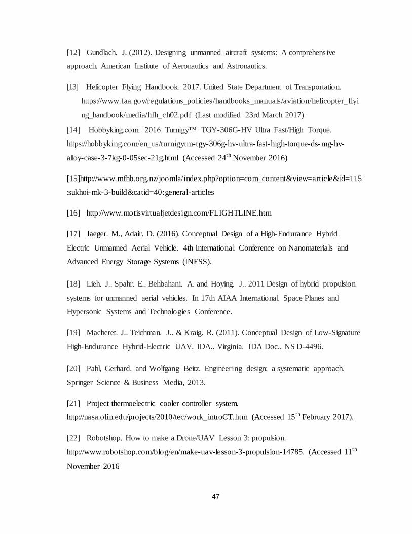
47
[12] Gundlach. J. (2012). Designing unmanned aircraft systems: A comprehensive
approach. American Institute of Aeronautics and Astronautics.
[13] Helicopter Flying Handbook. 2017. United State Department of Transportation.
https://www.faa.gov/regulations_policies/handbooks_manuals/aviation/helicopter_flyi
ng_handbook/media/hfh_ch02.pdf (Last modified 23rd March 2017).
[14] Hobbyking.com. 2016. Turnigy™ TGY-306G-HV Ultra Fast/High Torque.
https://hobbyking.com/en_us/turnigytm-tgy-306g-hv-ultra- fast-high-torque-ds-mg-hv-
alloy-case-3-7kg-0-05sec-21g.html (Accessed 24th November 2016)
[15]http://www.mfhb.org.nz/joomla/index.php?option=com_content&view=article&id=115
:sukhoi-mk-3-build&catid=40:general-articles
[16] http://www.motisvirtualjetdesign.com/FLIGHTLINE.htm
[17] Jaeger. M., Adair. D. (2016). Conceptual Design of a High-Endurance Hybrid
Electric Unmanned Aerial Vehicle. 4th International Conference on Nanomaterials and
Advanced Energy Storage Systems (INESS).
[18] Lieh. J.. Spahr. E.. Behbahani. A. and Hoying. J.. 2011 Design of hybrid propulsion
systems for unmanned aerial vehicles. In 17th AIAA International Space Planes and
Hypersonic Systems and Technologies Conference.
[19] Macheret. J.. Teichman. J.. & Kraig. R. (2011). Conceptual Design of Low-Signature
High-Endurance Hybrid-Electric UAV. IDA.. Virginia. IDA Doc.. NS D-4496.
[20] Pahl, Gerhard, and Wolfgang Beitz. Engineering design: a systematic approach.
Springer Science & Business Media, 2013.
[21] Project thermoelectric cooler controller system.
http://nasa.olin.edu/projects/2010/tec/work_introCT.htm (Accessed 15th February 2017).
[22] Robotshop. How to make a Drone/UAV Lesson 3: propulsion.
http://www.robotshop.com/blog/en/make-uav-lesson-3-propulsion-14785. (Accessed 11th
November 2016

48
[23] Ryll. M.. Bülthoff. H. H.. & Giordano. P. R. (2012. May). Modeling and control of a
quadrotor UAV with tilting propellers. In Robotics and Automation (ICRA). 2012 IEEE
International Conference on (pp. 4606-4613). IEEE.
[24] Saeed. A. S.. Younes. A. B.. Islam. S.. Dias. J.. Seneviratne. L.. & Cai. G. (2015.
June). A review on the platform design. dynamic modeling and control of hybrid UAVs.
In Unmanned Aircraft Systems (ICUAS). 2015 International Conference on (pp. 806-815).
IEEE.
[25] Schömann. J. (2014). Hybrid-electric propulsion systems for small unmanned
aircraft (Doctoral dissertation. Technische Universität München).
[26] Shampanier, M. /8th grade – Aerodynamics. http://www.portnet.k12.ny.us/Page/7890.
(Accessed 16th November 2016 )
[27] Tayal, S. P. "Engineering design process." International Journal of Computer Science
and Communication Engineering (2013): 1-5.
[28] T-motor. T-motor U7 power type brushless outrunner.
http://www.rctigermotor.com/html/2013/Power-Type_0928/92.html. (Accessed 11th
November 2016)
[29] Wikipedia. “Aircraft principal axes”. Last Modified 9 November 2016.
https://en.wikipedia.org/wiki/Aircraft_principal_axes
[30] Yoo, D. W., Oh, H. D., Won, D. Y., & Tahk, M. J. (2010, June). Dynamic modeling
and control system design for Tri-Rotor UAV. In Systems and Control in Aeronautics and
Astronautics (ISSCAA), 2010 3rd International Symposium on (pp. 762-767). IEEE
[31] Youtube. Foxtech Motor S3508 Thrust Test Video.
https://www.youtube.com/watch?v=maisALyuINo. (Accessed 10th November 2016)

49
APPENDICES
Appendix A. Experiment related material
1) Code for Arduino
#include <Servo.h>
Servo yservo; Servo xservo; // servos for x and y
//set initial values for x and y
int ypos = 0;
int xpos= 0;
void setup()
xservo.attach(14); //(analog pin 0) for the x servo
yservo.attach(9); //(pwm pin) for the y server
Serial.begin(19200); // 19200 is the rate of communication
Serial.println("Rolling"); // some output for debug purposes.
void loop()
static int v = 0; // value to be sent to the servo (0-180)
if ( Serial.available())
char ch = Serial.read(); // read in a character from the serial port and assign to ch
switch(ch) // switch based on the value of ch
case '0'...'9': // if it's numeric
v = v * 10 + ch - '0';
/*
so if the chars sent are 45x (turn x servo to 45 degs)..
v is the value we want to send to the servo and it is currently 0
The first char (ch) is 4 so
0*10 = 0 + 4 - 0 = 4;
Second char is 4;

50
4*10 = 40 + 5 = 45 - 0 = 45;
Third char is not a number(0-9) so we drop through...
*/
break;
case 'x': // if it's x
/*
....and land here
where we send the value of v which is now 45 to the x servo
and then reset v to 0
*/
xservo.write(v);
v = 0;
break;
case 'y':
yservo.write(v);
v = 0;
break;
2) Code for Processing:
import processing.serial.*;
int xpos=90; // set x servo's value to mid point (0-180);
int ypos=90; // and the same here
Serial port; // The serial port we will be using
void setup()
size(360, 360);

51
frameRate(100);
println(Serial.list()); // List COM-ports
//select second com-port from the list (COM3 for my device)
// You will want to change the [1] to select the correct device
// Remember the list starts at [0] for the first option.
port = new Serial(this, Serial.list()[0], 19200);
void draw()
fill(175);
rect(0,0,360,360);
fill(255,0,0); //rgb value so RED
rect(180, 175, mouseX-180, 10); //xpos, ypos, width, height
fill(0,255,0); // and GREEN
rect(175, 180, 10, mouseY-180);
update(mouseX, mouseY);
void update(int x, int y)
//Calculate servo postion from mouseX
if (mousePressed)
ypos=100;
else
xpos= x/2;
ypos = y/2;
//Output the servo position ( from 0 to 180)
port.write(xpos+"x");

52
port.write(ypos+"y");
3) Pictures of the laboratory setup
Figure A1. IC engine and DC motor connection
Figure A2. 3-phase rectifier connection

53
Figure A3. Resistors on breadboard
Figure A4. Ignition and tachometer wiring
Appendix B. Mathematical modeling
𝐿 𝑡𝑏=
1
2∗ 𝜌 ∗ 𝐶𝐿𝑡
∗ 𝐴𝑡 ∗ 𝑉𝑖𝑛2
𝐿𝑤𝑏=
1
2∗ 𝜌 ∗ 𝐶𝐿𝑤
∗ 𝐴𝑤 ∗ 𝑉𝑖𝑛2
𝐷𝑡𝑏=
1
2∗ 𝜌 ∗ 𝐶𝐷𝑡
∗ 𝐴𝑡 ∗ 𝑉𝑖𝑛2
𝐷𝑤𝑏=
1
2∗ 𝜌 ∗ 𝐶𝐷𝑤
∗ 𝐴𝑤 ∗ 𝑉𝑖𝑛2
𝑉𝑖𝑛 = √𝑉2 +2∗𝑇
𝜌∗𝐴𝑚, where
𝐴𝑡 is the are of the stabilizer, 𝐴𝑤 is the are of the wing, 𝐴𝑚 is the are of the motor,
𝐶𝐿𝑡,𝐶𝐿𝑤
,𝐶𝐷𝑡, 𝐶𝐷𝑤
are lift and drag coefficients for stabilizer and wing respectively,

54
𝑉𝑖𝑛 is the velocity of the UAV and V is the velocity of the motor
Translational kinematics:
Considering the translational motion of the aircraft, this is direct transformation changing
linear velocities (u, v,w) , from F𝐵 into F𝑉
[𝑥
𝑦
𝑧
]=R[𝑢𝑣𝑤
].
[𝑥
𝑦
𝑧
] = [𝑐𝑜𝑠ϴ𝑐𝑜𝑠ψ 𝑠𝑖𝑛ϕ𝑠𝑖𝑛ϴ𝑐𝑜𝑠ψ −𝑐𝑜𝑠ϕ𝑠𝑖𝑛ψ 𝑐𝑜𝑠ϕ𝑠𝑖𝑛ϴ𝑐𝑜𝑠ψ+ 𝑠𝑖𝑛ϕ𝑠𝑖𝑛ψ𝑐𝑜𝑠ϴ𝑠𝑖𝑛ψ 𝑠𝑖𝑛ϕ𝑠𝑖𝑛ϴ𝑠𝑖𝑛ψ +𝑐𝑜𝑠ϕ𝑠𝑖𝑛ψ 𝑐𝑜𝑠ϕ𝑠𝑖𝑛ϴ𝑠𝑖𝑛ψ− 𝑠𝑖𝑛ϕ𝑐𝑜𝑠ψ
−𝑠𝑖𝑛ϴ 𝑠𝑖𝑛ϕ𝑐𝑜𝑠ϴ 𝑐𝑜𝑠ϕ𝑐𝑜𝑠ϴ
][𝑢𝑣𝑤
]
Rotational kinematics:
𝜽 = [𝜙 𝜃 𝜓]𝑇
This transformation is obtained by sequential transformation of axes and angular velocities,
[ϕ
ϴ
ψ
] = [1 𝑠𝑖𝑛ϕ𝑡𝑎𝑛ϴ 𝑐𝑜𝑠ϕ𝑡𝑎𝑛ϴ
0 𝑐𝑜𝑠ϕ −𝑠𝑖𝑛ϕ
0 𝑠𝑖𝑛ϕ𝑠𝑒𝑐ϴ 𝑐𝑜𝑠ϕ𝑠𝑒𝑐ϴ
] [𝑝𝑞𝑟]
Translational dynamics:
Considering that the mass of the aircraft is constant, the state variables related to
translational dynamics can be calculated according to Newton’s Second Law: the
summation of all external forces acting on a rigid body is equal to the time rate of change
of the linear momentum of the body. This is shown by eqn (22)
[
] = [
𝑐𝑜𝑠ϴ𝑐𝑜𝑠ψ 𝑠𝑖𝑛ϕ𝑠𝑖𝑛ϴ𝑐𝑜𝑠ψ− 𝑐𝑜𝑠ϕ𝑠𝑖𝑛ψ 𝑐𝑜𝑠ϕ𝑠𝑖𝑛ϴ𝑐𝑜𝑠ψ+𝑠𝑖𝑛ϕ𝑠𝑖𝑛ψ𝑐𝑜𝑠ϴ𝑠𝑖𝑛ψ 𝑠𝑖𝑛ϕ𝑠𝑖𝑛ϴ𝑠𝑖𝑛ψ+ 𝑐𝑜𝑠ϕ𝑠𝑖𝑛ψ 𝑐𝑜𝑠ϕ𝑠𝑖𝑛ϴ𝑠𝑖𝑛ψ −𝑠𝑖𝑛ϕ𝑐𝑜𝑠ψ−𝑠𝑖𝑛ϴ 𝑠𝑖𝑛ϕ𝑐𝑜𝑠ϴ 𝑐𝑜𝑠ϕ𝑐𝑜𝑠ϴ
]
𝑇
[
00𝑔] +
1
𝑚𝑭𝐴,𝑇
𝑏 − [
𝑝𝑞𝑟] × [
𝑢𝑣𝑤
]
𝑭𝐴,𝑇𝑏 = [
𝑭𝐴,𝑇𝑥𝑏
𝑭𝐴,𝑇𝑦𝑏
𝑭𝐴,𝑇𝑧
𝑏
]
After performing some calculations and leaving the derivatives of the state variables alone
at the left side, we obtain

55
[
] =
[ 𝑟𝑣 − 𝑞𝑤 − 𝑔𝑠𝑖𝑛ϴ +
𝑭𝐴,𝑇𝑥𝑏
𝑚
𝑝𝑤 − 𝑟𝑢 + 𝑔𝑐𝑜𝑠ϴ𝑠𝑖𝑛ϕ +𝑭𝐴,𝑇𝑦
𝑏
𝑚
𝑞𝑢 − 𝑝𝑣 + 𝑔𝑐𝑜𝑠ϴ𝑐𝑜𝑠ϕ +𝑭𝐴,𝑇𝑧
𝑏
𝑚 ]
Rotational dynamics:
Applying Euler's formula; the summation of the external moments acting on a rigid body is
equal to the time rate of change of the angular momentum,
𝐼 [
] = − [𝑝𝑞𝑟] × (𝐼 [
𝑝𝑞𝑟]) + [
𝚪𝐴,𝑇𝑥
𝚪𝐴,𝑇𝑦
𝚪𝐴,𝑇𝑧
], or this can be re-written as
[
] = −𝐼−1 [𝑝𝑞𝑟] × (𝐼 [
𝑝𝑞𝑟]) + 𝐼−1 [
𝚪𝐴,𝑇𝑥
𝚪𝐴,𝑇𝑦
𝚪𝐴,𝑇𝑧
]
𝐼 = [
𝐼𝑥𝑥 𝐼𝑥𝑦 𝐼𝑥𝑧
𝐼𝑦𝑥 𝐼𝑦𝑦 𝐼𝑦𝑧
𝐼𝑧𝑥 𝐼𝑧𝑦 𝐼𝑧𝑧
], 𝐼𝑥𝑦 = 𝐼𝑦𝑥, 𝐼𝑥𝑧 = 𝐼𝑧𝑥, 𝐼𝑦𝑧 = 𝐼𝑧𝑦
So after consecutive calculations;
[
] = −𝑰−𝟏 [
−𝑰𝒙𝒛𝒑𝒒− 𝑰𝒚𝒛𝒒𝟐 + 𝑰𝒛𝒛𝒒𝒓+ 𝑰𝒙𝒚𝒑𝒓 − 𝑰𝒚𝒚𝒒𝒓 + 𝑰𝒚𝒛𝒓
𝟐
𝑰𝒙𝒙𝒑𝒓 − 𝑰𝒙𝒚𝒒𝒓 − 𝑰𝒙𝒛𝒓𝟐 + 𝑰𝒙𝒛𝒑
𝟐 + 𝑰𝒚𝒛𝒑𝒒 − 𝑰𝒛𝒛𝒑𝒓
−𝑰𝒙𝒚𝒑𝟐 + 𝑰𝒚𝒚𝒑𝒒 − 𝑰𝒚𝒛𝒑𝒓 − 𝑰𝒙𝒙𝒑𝒒 + 𝑰𝒙𝒚𝒒𝟐 + 𝑰𝒙𝒛𝒓𝒒
] + 𝑰−𝟏 [
𝚪𝑨,𝑻𝒙
𝚪𝑨,𝑻𝒚
𝚪𝑨,𝑻𝒛
]
Appendix C. 3D modeling design
Figure C1. CAD drawing

56
Figure C2. Wing specifications
Figure C3. Horizontal flight
Figure C4. Rear tilt rotor mechanism
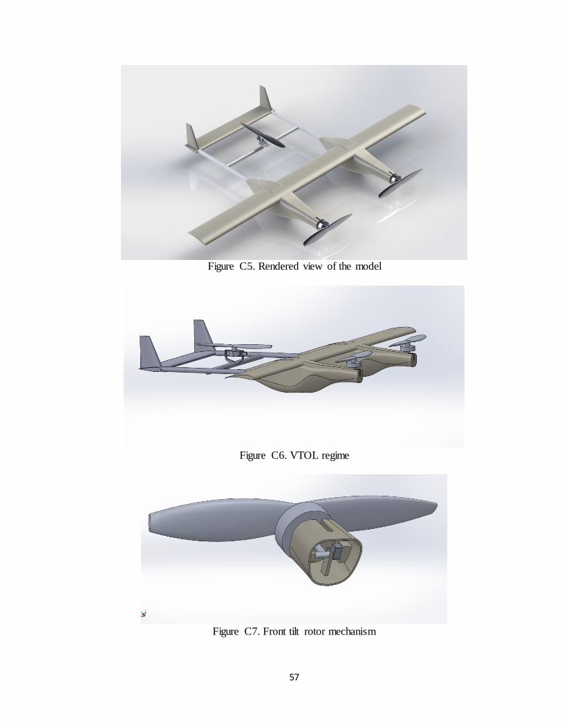
57
Figure C5. Rendered view of the model
Figure C6. VTOL regime
Figure C7. Front tilt rotor mechanism