designing a water distribution system in a site ... · pdf filedesigning a water distribution...
TRANSCRIPT

1 Copyright © 2014 Bentley Systems, Incorporated
Designing a Water Distribution
System in a Site Development
Project Using WaterGEMS
Workshop Overview
In this workshop, you will learn about the benefits of using the MicroStation platform in
conjunction with WaterCAD or WaterGEMS. You will also learn about designing a water
distribution system extension in a new site development project, and how to review a
water system’s fire flow capacity.
This course material has been developed for the WaterCAD or WaterGEMS V8i
SELECTseries 5 Version 08.11.05.61 and MicroStation V8i SELECTseries 3 Version
08.11.09.459. (WaterCAD and WaterGEMS have also received limited testing on some
prior versions of MicroStation V8i.)
Although you will use WaterCAD V8i on the MicroStation platform during this workshop,
the interface and layout tools learned are equally applicable to WaterCAD, SewerCAD,
SewerGEMS, StormCAD, CivilStorm, HAMMER, and PondPack.
Learning Objectives
After this course you will be able to:
• Apply the basic principles of water distribution modeling in the MicroStation V8i
environment
• Open or create a new hydraulic model from with MicroStation
• Import a CAD file as a background and lay out new hydraulic model elements using
AccuDraw and AccuSnap
• Set up levels for each hydraulic element type and have new elements automatically
placed on the correct level

General Information on MicroStation Integration
2 Copyright © 2014 Bentley Systems, Incorporated
• Set up View Associations and Symbology Definitions
• Use the Print Preparation Tool
• Publish a 3D i-model of the hydraulic network
General Information on MicroStation Integration
In the MicroStation V8i environment you can create and model your network directly
within your primary drafting environment. This gives you access to all of MicroStation's
powerful drafting and presentation tools, while still enabling you to perform hydraulic
modeling tasks like editing, solving, and data management. This relationship between
the two applications enables extremely detailed and accurate mapping of model
features, and provides the full array of output and presentation features available in
MicroStation V8i. This facility provides the most flexibility and the highest degree of
compatibility with other CAD-based applications and drawing data maintained at your
organization.
Bentley WaterGEMS V8i features support for MicroStation V8i integration. You can run
Bentley WaterGEMS V8i in both MicroStation and the stand-alone environment.
The MicroStation functionality has been implemented in a way that is the same as the
Bentley WaterGEMS V8i base product. Once you become familiar with the stand-alone
environment, you will not have any difficulty using the product in the MicroStation
environment.
In the MicroStation V8i environment, you will have access to the full range of
functionality available in the MicroStation design and drafting environment. The
standard environment is extended and enhanced by using MicroStation's MDL
(MicroStation Development Language) client layer that lets you create, view, and edit
the native Bentley WaterGEMS V8i network model while in MicroStation.
MDL is a complete development environment that lets applications take full advantage
of the power of MicroStation and MicroStation-based vertical applications. MDL can be
used to develop simple utilities, customized commands or sophisticated commercial
applications for vertical markets.
Some of the advantages of working in the MicroStation V8i environment include:
• Lay out network links and structures in fully-scaled environment in the same
design and drafting environment that you use to develop your engineering
plans.
• Have access to any other third party applications that you currently use,
along with any custom MDL applications.

General Information on MicroStation Integration
3 Copyright © 2014 Bentley Systems, Incorporated
• Use native MicroStation insertion snaps to precisely position hydraulic
network elements with respect to other entities in the MicroStation drawing.
• Use native MicroStation commands on hydraulic model entities with
automatic update and synchronization with the model database.
• Control destination levels for model elements and associated label text and
annotation, giving you control over styles, line types, and visibility of model
elements.
Note: Bentley MicroStation V8i is the only MicroStation environment supported by
WaterGEMS V8i.
A Bentley MicroStation WaterGEMS V8i project consists of:
• Drawing File (.DGN)—The MicroStation drawing file contains the elements that
define the model, in addition to the planimetric base drawing information that
serves as the model background.
• Hydraulic Model File (e.g. .WTG)—The model file contains model data specific to
the hydraulic model, including project option settings, color-coding and annotation
settings, etc. Note that the MicroStation .dgn that is associated with a particular
hydraulic model may not necessarily have the same filename as the model's .wtg
file.
• Database File (.sqlite)—The hydraulic model database file efficiently contains all of
the input and output data for the hydraulic model in a small file. Note that the
MicroStation .dgn that is associated with a particular model may not have the same
file name as the model's database file. Recent version of WaterGEMS used (*.sqlite)
files as a database storage.
When you start Bentley WaterGEMS V8i for MicroStation V8i, you will see the dialog
below. You must identify a new or existing MicroStation dgn drawing file to be
associated with the model before you can open a Bentley WaterGEMS V8i model.

General Information on MicroStation Integration
4 Copyright © 2014 Bentley Systems, Incorporated
From here you can either browse to an existing dgn file or create a new file using the
New button on the top toolbar. Once you have selected a file, you can pick the Open
button.
Once a drawing is open, you can use the WaterGEMS V8i Project drop down menu to
create a new WaterGEMS V8i project, attach an existing project, import a project or
open a project from ProjectWise.
There are a number of options for creating a model in the MicroStation client:
• Create a model from scratch—You can create a model in MicroStation. You'll first
need to create a new MicroStation .dgn (refer to your MicroStation documentation
to learn how to create a new .dgn). Start WaterGEMS V8i for MicroStation. In the
first dialog, pick the New button and assign a name and path to the DGN file. Once
the dgn is open, use the New command in the WaterGEMS V8i Project menu
(Project > New). This will create a new WaterGEMS V8i project file and attach it to
the Bentley MicroStation .dgn file. Once the file is created you can start creating
WaterGEMS V8i elements that exist in both the WaterGEMS V8i database and in the
.dgn drawing. See Working with Elements and Working with Elements Using
MicroStation Commands for more details.
• Open a previously created WaterGEMS V8i project—You can open a previously
created WaterGEMS V8i model and attach it to a .dgn file. To do this, start
WaterGEMS V8i for MicroStation. Open or create a new MicroStation .dgn file (refer
to your MicroStation documentation to learn how to create a new .dgn). Use the
Project menu on the WaterGEMS V8i toolbar and click on the Project > "Attach
Existing..." command, then select an existing WaterGEMS V8i.wtg file. The model
will now be attached to the .dgn file and you can edit, delete, and modify the
WaterGEMS V8i elements in the model. All MicroStation commands can be used on
WaterGEMS V8i elements.
• Import a model that was created in another modeling application—There are four
types of files that can be imported into WaterGEMS V8i:
• WaterGEMS / HAMMER Database—this can either be a HAMMER V8i or V8,
WaterGEMS V8i or V3, or WaterCAD V8i or V7 database. The model will be
processed and imported into the active MicroStation .dgn drawing.
• EPANET—You can import EPANET input (.inp) files. The file will be processed
and the proper elements will be created and added to the MicroStation
drawing.
• Submodel—You can import a WaterGEMS V8i V8 subenvironment into the
MicroStation drawing file.
• Bentley Water model—You can import Bentley Water model data into your
WaterGEMS V8i model in MicroStation.

Project Creation and Entering System Information
5 Copyright © 2014 Bentley Systems, Incorporated
If you want to trace the model on top of a dgn or other background file, you would load
the background into the dgn first by using either File/Reference or File/Raster Manager
Then you start laying out elements over top of the background.
In this workshop you will be creating a hydraulic model from scratch with the aid of a
background drawing that you will attach to your DGN.
Project Creation and Entering System Information
� Exercise: Creating a new WaterGEMS Project in MicroStation
In this exercise you will create a new MicroStation DGN and WaterGEMS project file.
You will then enter the project’s properties and set up the element levels.
1 Start “WaterGEMS V8i for MicroStation V8i (SELECTseries 3)” from the start
menu under Bentley or from the desktop icon.
You will be brought to the File Open dialog when WaterGEMS V8i for
MicroStation V8i SELECTseries 3 opens. The primary function of this dialog is
navigating to and opening design files.
2 Click the New File icon in the top right of the File Open dialog.
3 In the New dialog, browse to C:\Bentley Workshop\WaterCAD-
GEMS_MSintegration\
4 Enter a File name of Scaled_Network and click Save.

Project Creation and Entering System Information
6 Copyright © 2014 Bentley Systems, Incorporated
You will be brought back to the File Open dialog to open the file you just created.
5 Make sure Scaled_Network.dgn is selected, and click Open.
You are now in the MicroStation V8i interface. You should see a menu item at
the top of the dialog that says WaterGEMS. This allows you to access the
WaterGEMS menu items.
6 Select WaterGEMS > Project > Attach New.
This will bring up the Save As dialog so that you can save the WaterGEMS
project.
Project Creation and Entering System Information
7 Copyright © 2014 Bentley Systems, Incorporated
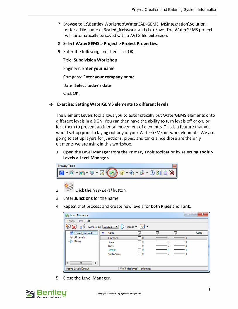
7 Browse to C:\Bentley Workshop\WaterCAD-GEMS_MSintegration\Solution,
enter a File name of Scaled_Network, and click Save. The WaterGEMS project
will automatically be saved with a .WTG file extension.
8 Select WaterGEMS > Project > Project Properties.
9 Enter the following and then click OK.
Title: Subdivision Workshop
Engineer: Enter your name
Company: Enter your company name
Date: Select today’s date
Click OK
� Exercise: Setting WaterGEMS elements to different levels
The Element Levels tool allows you to automatically put WaterGEMS elements onto
different levels in a DGN. You can then have the ability to turn levels off or on, or
lock them to prevent accidental movement of elements. This is a feature that you
would set up prior to laying out any of your WaterGEMS network elements. We are
going to set up layers for junctions, pipes, and tanks since those are the only
elements we are using in this workshop.
1 Open the Level Manager from the Primary Tools toolbar or by selecting Tools >
Levels > Level Manager.
2 Click the New Level button.
3 Enter Junctions for the name.
4 Repeat that process and create new levels for both Pipes and Tank.
5 Close the Level Manager.

Project Creation and Entering System Information
8 Copyright © 2014 Bentley Systems, Incorporated
We now need to set the elements to their levels.
6 Select WaterGEMS > View > Element Levels.
This opens the Element Levels dialog.
7 For the Pipe row, select Pipes for both the Element Level and the Annotation
Level columns.
8 Repeat this for Junction and Tank.
9 Click OK.
� Exercise: Reviewing WaterGEMS Tasks
Now that we have the model set up to begin laying out our network, let’s take a few
moments to review the interface a little bit further.

Project Creation and Entering System Information
9 Copyright © 2014 Bentley Systems, Incorporated
The WaterGEMS tasks can be found in the Tasks dialog (default location is the left
side of the MicroStation Interface) or under the WaterGEMS menu. You may need to
scroll down the Tasks list
A task is simply a logical grouping of tools organized by use. For example, the Layout
(WaterGEMS) task contains all of the elements that can be used in a WaterGEMS
model.
1 Click on each WaterGEMS task group to view the options contained in each.
2 Use the buttons in the upper right corner of a task group to change the Layout
Mode to the one you most prefer: Icon, List or Panel.
� Exercise: Creating pipe prototypes
Before you begin drawing the new water network, you will set up pipe prototypes.
Prototypes contain the default values that will be assigned to new elements in your
network.
Prototypes can reduce data entry requirements dramatically if a group of network
elements share common data. For example, if a section of the network contains all
12-inch pipes, use the Prototype manager to set the Pipe Diameter field to 12
inches. When you create a new pipe in your model, its diameter attribute will
default to 12 inches.
In this workshop, the pipe prototype will be set to 6-inch diameter with PVC for
material and a C-factor of 150.
Project Creation and Entering System Information
10 Copyright © 2014 Bentley Systems, Incorporated
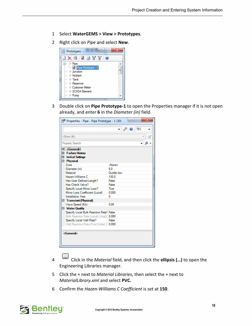
1 Select WaterGEMS > View > Prototypes.
2 Right click on Pipe and select New.
3 Double click on Pipe Prototype-1 to open the Properties manager if it is not open
already, and enter 6 in the Diameter (in) field.
4 Click in the Material field, and then click the ellipsis (…) to open the
Engineering Libraries manager.
5 Click the + next to Material Libraries, then select the + next to
MaterialLibrary.xml and select PVC.
6 Confirm the Hazen-Williams C Coefficient is set at 150.

Project Creation and Entering System Information
11 Copyright © 2014 Bentley Systems, Incorporated
7 Click Select.
Note: The Hazen-Williams C field automatically updates to 150 once PVC has been assigned
as the Material.
8 Close the Prototypes manager.
� Exercise: Importing a CAD file to use in network layout
Before we begin, we want to change the background color to white.
1 Select Workspace > Preferences.
2 Select View Options and check the box for Design Model Background Color.
3 Click the color swatch and change the color from black to white and click OK.

Project Creation and Entering System Information
12 Copyright © 2014 Bentley Systems, Incorporated
4 Click OK again to exit the Preferences dialog.
5 Select Settings > Design File and select Working Units.
6 Change Master Unit to Feet and click OK.
7 Select File > Import > CAD Files.
8 Browse to C:\Bentley Workshop\WaterCAD-GEMS_MSintegration.
9 Select Scaled_Network.dxf and click Open.

Project Creation and Entering System Information
13 Copyright © 2014 Bentley Systems, Incorporated
10 Click the Fit View button at the top of View 1 to view the map.
11 Select File > Save.
� Exercise: Laying out the network
1 Select WaterGEMS > Tools > Options and click on the Drawing tab.
2 Change the following:
Symbol Size Multiplier: 5
Text Height Multiplier: 5

Project Creation and Entering System Information
14 Copyright © 2014 Bentley Systems, Incorporated
Note: In the Element Symbology (WaterGEMS > View > Element Symbology) dialog
click the Drawing Style button to choose between CAD or GIS style. If you want the
CAD style change the multipliers as mentioned above; if you want the GIS style leave
the multipliers set to 1.0.
3 Click OK and click Yes on the Synchronization message that comes up.

Project Creation and Entering System Information
15 Copyright © 2014 Bentley Systems, Incorporated
Follow the next set of instructions to layout the network as shown in the following picture:
4 Before you begin, make sure that AccuDraw is toggled on and you see the
following dialog appear on your screen.
Note: You may see the Accudraw dialog at the bottom of your screen:
5 Click the Pipe Layout tool from the Layout (WaterGEMS) task group and
move your cursor over to the drawing pane.
This will bring up the WaterGEMS Layout Pipe dialog. In this dialog you will
choose the type of node you want to lay out at the beginning of the pipe.
Project Creation and Entering System Information
16 Copyright © 2014 Bentley Systems, Incorporated
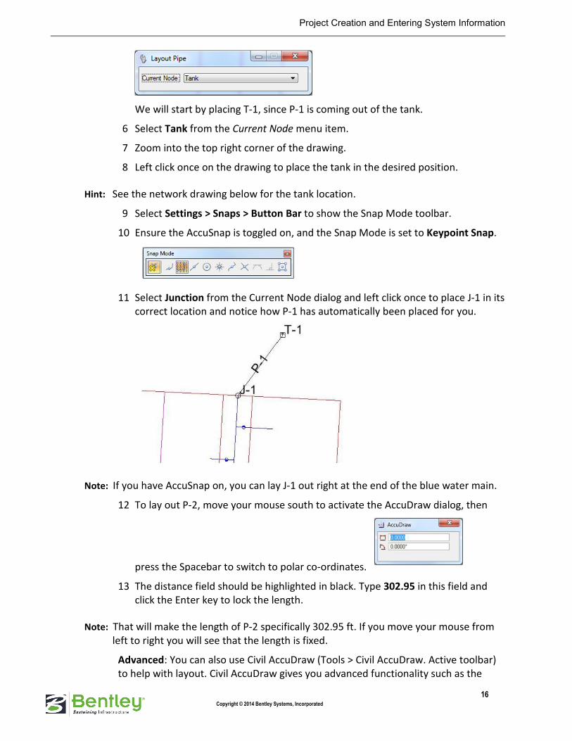
We will start by placing T-1, since P-1 is coming out of the tank.
6 Select Tank from the Current Node menu item.
7 Zoom into the top right corner of the drawing.
8 Left click once on the drawing to place the tank in the desired position.
Hint: See the network drawing below for the tank location.
9 Select Settings > Snaps > Button Bar to show the Snap Mode toolbar.
10 Ensure the AccuSnap is toggled on, and the Snap Mode is set to Keypoint Snap.
11 Select Junction from the Current Node dialog and left click once to place J-1 in its
correct location and notice how P-1 has automatically been placed for you.
Note: If you have AccuSnap on, you can lay J-1 out right at the end of the blue water main.
12 To lay out P-2, move your mouse south to activate the AccuDraw dialog, then
press the Spacebar to switch to polar co-ordinates.
13 The distance field should be highlighted in black. Type 302.95 in this field and
click the Enter key to lock the length.
Note: That will make the length of P-2 specifically 302.95 ft. If you move your mouse from
left to right you will see that the length is fixed.
Advanced: You can also use Civil AccuDraw (Tools > Civil AccuDraw. Active toolbar)
to help with layout. Civil AccuDraw gives you advanced functionality such as the

Project Creation and Entering System Information
17 Copyright © 2014 Bentley Systems, Incorporated
ability to specify a point by entering the Station and Offset from an existing
alignment. If you have time, feel free to experiment with Civil AccuDraw.
14 Left click to place J-2 at the intersection shown in the network layout.
15 Continue laying out junctions J-3 through J-6 following the drawing until you
reach J-6.
Note: You do not have to use AccuDraw for any of the other pipes. Steps 10 through 12
were just to show you how that feature works. The pipes will automatically pick up
the pipe length when you lay them out, since this a scaled drawing.
16 After laying out J-6, right click to reset the active tool.
17 Click on J-2 and go across the diagram, click to layout J-7, then up to J-8, right
click to reset.
18 Connect J-7 to J-4 and right click to reset.
19 Click on J-5 and move across and click to create J-9, right click to reset.
� Exercise: Entering pipe data
1 Click the Select tool from the Layout task group, and click on P-1 to open
the Properties manager.
2 Enter the following:
Has User Defined Length?: True
Length (User Defined) (ft): 450

Project Creation and Entering System Information
18 Copyright © 2014 Bentley Systems, Incorporated
� Exercise: Entering tank data
1 Click on T-1 in the drawing to change the open Properties manager to the tank
properties.
2 Enter the following:
Elevation (Base) (ft): 650
Elevation (Minimum) (ft): 650
Elevation (Initial) (ft): 665
Elevation (Maximum) (ft): 680
Elevation (ft): 650
Diameter (ft): 50
� Exercise: Entering junction data
1 Select WaterGEMS > View > FlexTables or click the FlexTables button in
the View task group.
2 Double click Junction Table under Tables Predefined to open the Junction
FlexTable.

Project Creation and Entering System Information
19 Copyright © 2014 Bentley Systems, Incorporated
3 Right click on the Label column and select Sort > Sort Ascending.
4 Enter the elevations from the table below for each node:
Junction Elevation (ft)
J-1 620
J-2 605
J-3 580
J-4 545
J-5 510
J-6 580
J-7 580
J-8 600
J-9 490
Your FlexTable should look similar to the following:

Project Creation and Entering System Information
20 Copyright © 2014 Bentley Systems, Incorporated
5 Close the FlexTable: Junction Table and the FlexTables manager.
6 Save your file.
� Exercise: Using the Demand Control Center
1 Select WaterGEMS > Tools > Demand Control Center.
The message below will come up on your screen:
2 Click Yes to continue to the Demand Control Center.
3 Click the New button and select Initialize Demands for All Elements.
This will add all of the junctions in the model to the table so that flows and
patterns can be entered for them.
4 Right click the Demand (Base) (gpm) column header and select Global Edit.

Project Creation and Entering System Information
21 Copyright © 2014 Bentley Systems, Incorporated
5 Enter 20 as the Value and then click OK.
6
This will set the demands for all the junctions to 20.
7 Click Close on the Demand Control Center dialog.
� Exercise: Reviewing Calculation Options
1 Select WaterGEMS > Analysis > Calculation Options or click the Calculation
Options button in the Analysis task group.
2 Double click Base Calculation Options under Steady State/EPS Solver to open the
Properties manager.

Project Creation and Entering System Information
22 Copyright © 2014 Bentley Systems, Incorporated
Note: You may dock the Properties dialog if it is more convenient.
3 Make sure the Friction Method is set to Hazen-Williams.
4 Close the Calculation Options manager by clicking the X.
� Exercise: Computing the model and reviewing results
1 Select WaterGEMS > Analysis > Validate or click the Validate button in the
Analysis task group.
The validate command verifies that there are no problems with the model.
2 Select WaterGEMS > Analysis > Compute or click the Compute button.
When the run has completed, the Calculation Summary dialog opens.
3 Review the Calculation Summary, and then close it.
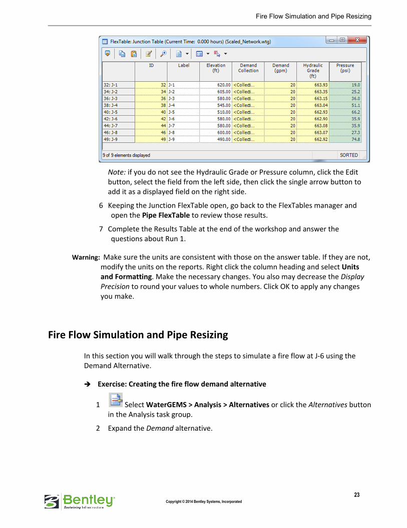
4 Go to the FlexTables manager and open the Junction Table under Tables-
Predefined.
5 Review the Pressure and Hydraulic Grade columns.
Fire Flow Simulation and Pipe Resizing
23 Copyright © 2014 Bentley Systems, Incorporated
Note: if you do not see the Hydraulic Grade or Pressure column, click the Edit
button, select the field from the left side, then click the single arrow button to
add it as a displayed field on the right side.
6 Keeping the Junction FlexTable open, go back to the FlexTables manager and
open the Pipe FlexTable to review those results.
7 Complete the Results Table at the end of the workshop and answer the
questions about Run 1.
Warning: Make sure the units are consistent with those on the answer table. If they are not,
modify the units on the reports. Right click the column heading and select Units
and Formatting. Make the necessary changes. You also may decrease the Display
Precision to round your values to whole numbers. Click OK to apply any changes
you make.
Fire Flow Simulation and Pipe Resizing
In this section you will walk through the steps to simulate a fire flow at J-6 using the
Demand Alternative.
� Exercise: Creating the fire flow demand alternative
1 Select WaterGEMS > Analysis > Alternatives or click the Alternatives button
in the Analysis task group.
2 Expand the Demand alternative.
Fire Flow Simulation and Pipe Resizing
24 Copyright © 2014 Bentley Systems, Incorporated
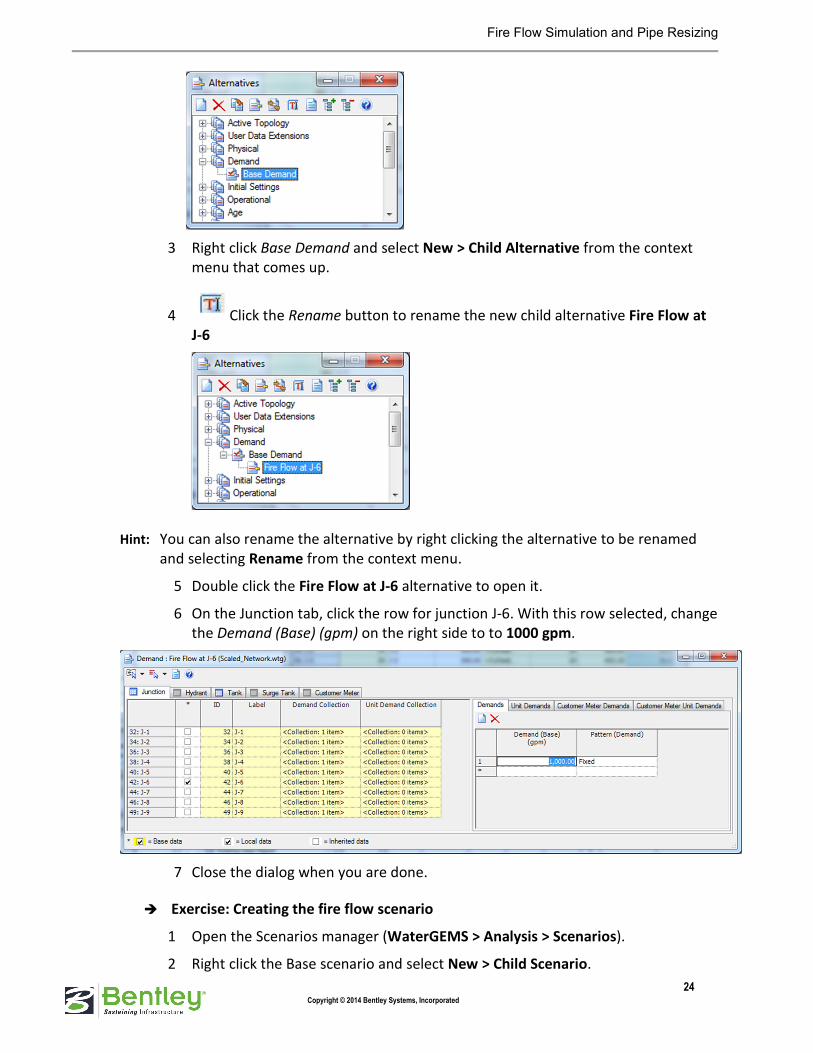
3 Right click Base Demand and select New > Child Alternative from the context
menu that comes up.
4 Click the Rename button to rename the new child alternative Fire Flow at
J-6
Hint: You can also rename the alternative by right clicking the alternative to be renamed
and selecting Rename from the context menu.
5 Double click the Fire Flow at J-6 alternative to open it.
6 On the Junction tab, click the row for junction J-6. With this row selected, change
the Demand (Base) (gpm) on the right side to to 1000 gpm.
7 Close the dialog when you are done.
� Exercise: Creating the fire flow scenario
1 Open the Scenarios manager (WaterGEMS > Analysis > Scenarios).
2 Right click the Base scenario and select New > Child Scenario.

Fire Flow Simulation and Pipe Resizing
25 Copyright © 2014 Bentley Systems, Incorporated
3 Enter the scenario name as Fire Flow at J-6.
4 Double click Fire Flow at J-6 to open the Properties manager.
5 Select Fire Flow at J-6 as the Demand alternative.
6 Back in the Scenarios manager, select Fire Flow at J-6 and select the Make
Current button.
Note: Note that the Fire Flow at J-6 scenario icon now has a red check mark on it. That
indicates which scenario is the current scenario.
7 Click the Compute button in the Scenarios manager or on the main toolbar.
8 Review the results and complete the Results Table at the end of the workshop
and answer the questions about Run 2.
Note: A network of 6 inch pipes will not work well in this situation. The problem areas are
most likely those pipes with the highest velocities and/or friction slopes. Review the

Fire Flow Simulation and Pipe Resizing
26 Copyright © 2014 Bentley Systems, Incorporated
pipes with the highest velocities and hydraulic gradients in the pipe table. These pipes
will need to be upsized.
In this scenario we are going to try to fix the problem areas from the previous fire flow
run by upsizing the pipes with the highest velocities and friction slopes.
� Exercise: Creating a new physical alternative
1 Open the Alternatives manager (WaterGEMS > Analysis > Alternatives).
2 Expand Physical to view the Base Physical alternative.
3 Right click the Base Physical alternative and select New > Child Alternative.
4 Click the Rename button to rename the new child alternative New Diameters.
5 Double click New Diameters to edit it.
6 Change the diameters to the following:
Pipe Diameter (in)
P-1 10
P-2 10
P-3 8
P-4 8
P-5 8
P-6 8

Fire Flow Simulation and Pipe Resizing
27 Copyright © 2014 Bentley Systems, Incorporated
7 Close the “Physical: New Diameters (Scaled_Network)” dialog when you are
done.
� Exercise: Creating the new fire flow scenario for new diameters
1 Open the Scenarios manager (WaterGEMS > Analysis > Scenarios).
2 Select Base, click the New button, and select Base Scenario.
3 Enter the scenario name as Fire Flow with New Diameters.
4 Double click Fire Flow with New Diameters to open the Properties manager.
5 Select New Diameters as the Physical alternative and Fire Flow at J-6 as the
Demand alternative.
Results and Output
28 Copyright © 2014 Bentley Systems, Incorporated
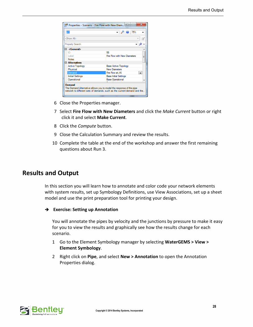
6 Close the Properties manager.
7 Select Fire Flow with New Diameters and click the Make Current button or right
click it and select Make Current.
8 Click the Compute button.
9 Close the Calculation Summary and review the results.
10 Complete the table at the end of the workshop and answer the first remaining
questions about Run 3.
Results and Output
In this section you will learn how to annotate and color code your network elements
with system results, set up Symbology Definitions, use View Associations, set up a sheet
model and use the print preparation tool for printing your design.
� Exercise: Setting up Annotation
You will annotate the pipes by velocity and the junctions by pressure to make it easy
for you to view the results and graphically see how the results change for each
scenario.
1 Go to the Element Symbology manager by selecting WaterGEMS > View >
Element Symbology.
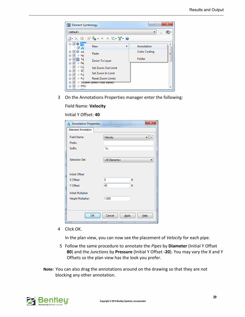
2 Right click on Pipe, and select New > Annotation to open the Annotation
Properties dialog.
Results and Output
29 Copyright © 2014 Bentley Systems, Incorporated
3 On the Annotations Properties manager enter the following:
Field Name: Velocity
Initial Y Offset: 40
4 Click OK.
In the plan view, you can now see the placement of Velocity for each pipe.
5 Follow the same procedure to annotate the Pipes by Diameter (Initial Y Offset
80) and the Junctions by Pressure (Initial Y Offset -20). You may vary the X and Y
Offsets so the plan view has the look you prefer.
Note: You can also drag the annotations around on the drawing so that they are not
blocking any other annotation.

Results and Output
30 Copyright © 2014 Bentley Systems, Incorporated
6 When you have annotated the Pipes and Junctions, change the current scenario,
using the Scenarios manager, to view how the annotations update as the
scenarios are changed.
� Exercise: Setting up color coding for pipes and junctions
Another way to view element results is with color coding. In this section we will set
up color coding for pipes by diameter and junctions by pressure.
1 In the Element Symbology manager, right click Pipe and select New Color
Coding.
This will bring up the Color Coding Properties - Pipe dialog.
2 Select Diameter for Field Name.
3 Click the Calculate Range button and select Full Range.
If the Fire Flow with New Diameter Scenario is current, you will see that this
populates the Minimum and Maximum fields with 6 in and 10 in pipes. If you see
6 in for the Maximum, change it to 10.
4 Change Steps to 3 since we only have 3 different diameters used in the model, 6,
8, and 10.
5 Set Options to Color and Size.
6 Click the Initialize button.
7 Set the Value, Color, and Size to the following:
Value <= (in) Color Size
6 Green 1
8 Blue 2
10 Red 3

Results and Output
31 Copyright © 2014 Bentley Systems, Incorporated
8 Click Apply and OK.
You will see that the pipes and their associated annotations are now color coded
according to their diameter.
9 Set up the Junction color coding for Pressure using Color and Size.
10 The default values that you get for the Minimum, Maximum, Steps, Value, Color,
and Size are fine so leave them as they come up.
11 Click Apply and OK. Your network drawing should look similar to the following:
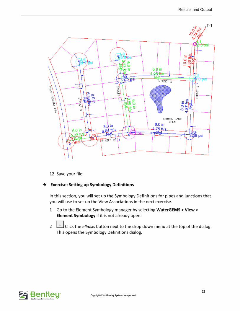
Results and Output
32 Copyright © 2014 Bentley Systems, Incorporated
12 Save your file.
� Exercise: Setting up Symbology Definitions
In this section, you will set up the Symbology Definitions for pipes and junctions that
you will use to set up the View Associations in the next exercise.
1 Go to the Element Symbology manager by selecting WaterGEMS > View >
Element Symbology if it is not already open.
2 Click the ellipsis button next to the drop down menu at the top of the dialog.
This opens the Symbology Definitions dialog.

Results and Output
33 Copyright © 2014 Bentley Systems, Incorporated
This is where we will create and name our symbology groups. We want to have
two groups. One group will be for the annotations and color coding to show our
results. The other group will be for the annotations and color coding to show the
physical properties of the pipes.
3 Click the New button to create a new definition.
4 Click the new symbology definition, click the Rename button and name the new
definition Results.
5 Repeat steps 3 and 4, but name the second definition Physical Properties.
6 Close out of the dialog when you are done to return to the Element Symbology
manager.
7 Using the drop down menu at the top of the Element Symbology manager, select
Results.
8 Expand Pipe and Junction symbology sections.
9 Select Label and Velocity for Pipe, and select Label, Pressure annotation, and
Pressure color coding for Junctions.

Results and Output
34 Copyright © 2014 Bentley Systems, Incorporated
10 Select Physical Properties from the drop down menu.
11 Expand Pipe and select Label, Diameter annotation, and Diameter color coding.
� Exercise: Setting up View Associations
Now that we have the annotations, color coding, and symbology definitions set up we
can set up the view associations.
View associations allow you to define the Element Symbology Definition and the
Scenario that is displayed for each MicroStation view.
There is a View Associations Scenario Mode button in the Scenarios Manager and
the Element Symbology Manager. This button allows you to toggle between
Independent and Synchronized view modes.
When Independent is selected, you can change the active scenario (or element
symbology) for the current view without changing the active scenario (or element
symbology) displayed in the other views.
When Synchronized is selected, changing the active scenario (or element symbology) in
the current view will also change the active scenario (or element symbology) in all of the
other views.
Multi-view Synchronized Mode:
• When the user is in multi-view synchronized mode, a change of the active
scenario and/or symbology definition will cause all view windows to update
to have that scenario and/or symbology definition to be used.
Multi-view Independent Mode:
• A user can only have one view window active (in focus) at any given time.
When the user changes a symbology definition, that newly active symbology
definition will now be used whenever that view window is active (or until the
user changes the active symbology definition again).

Results and Output
35 Copyright © 2014 Bentley Systems, Incorporated
• Likewise, when the user changes the current scenario, that newly active
scenario will now be used whenever that view window is active (or until the
user changes the current scenario again).
1 Select WaterGEMS > View > View Associations or click the View
Associations button in the View task group.
We are going to use 4 different views in this workshop to review the network.
2 Click the Scenario Mode button and select Independent Mode.
3 Click the Symbology Definition Mode button and select Independent
Mode.
4 Set the View Associations dialog up as follows using the drop down menus:
View Symbology
Definition
Scenario
View 1 Physical
Properties
Fire Flow at J-6
View 2 Physical
Properties
Fire Flow with New
Diameters
View 3 Results Fire Flow at J-6
View 4 Results Fire Flow with New
Diameters

Results and Output
36 Copyright © 2014 Bentley Systems, Incorporated
5 Close the View Associations dialog when you are done.
� Exercise: Setting up different views
Having WaterGEMS V8i integrated with MicroStation V8i allows you to take
advantage of the MicroStations 8 available views. You can set up each view to show
a different part of your water system, so that you do not have to keep zooming
and/or panning to get to a certain part of the system. You can also use of the View
Associations tool and set up different symbology displays for each view.
1 Turn on views 1 through 4 by selecting them in the status bar.
2 Select Window > Tile to arrange all four views equally in the MicroStation
interface.
3 Click in View 1 and select Fit View.
4 Click in View 2 and do the same, then issue a reset (right click in the drawing
pane).
5 Click in View 3 and in the Properties manager type T-1 in the search field, set the
zoom level to 100%, and then click the Find button to zoom in on the
tank.
6 Repeat step 5 for View 4. Your view should look like the following:

Results and Output
37 Copyright © 2014 Bentley Systems, Incorporated
Note: Note that in each view you are viewing different scenarios, color coding, annotations,
results, and physical properties of one model. The title of each view shows the
Symbology Definition being used along with which scenario is being shown.
In this example you can clearly see the change in velocity in pipe P-1 as a result of using
larger diameters in the Fire Flow with New Diameters scenario.
This brings us to the end of the workshop. The majority of the features shown in this
workshop are only available when using the MicroStation platform in conjunction with one
of the hydraulics and hydrology applications. Users can enjoy significant productivity
benefits by utilizing both applications together.
Assessment
38 Copyright © 2014 Bentley Systems, Incorporated
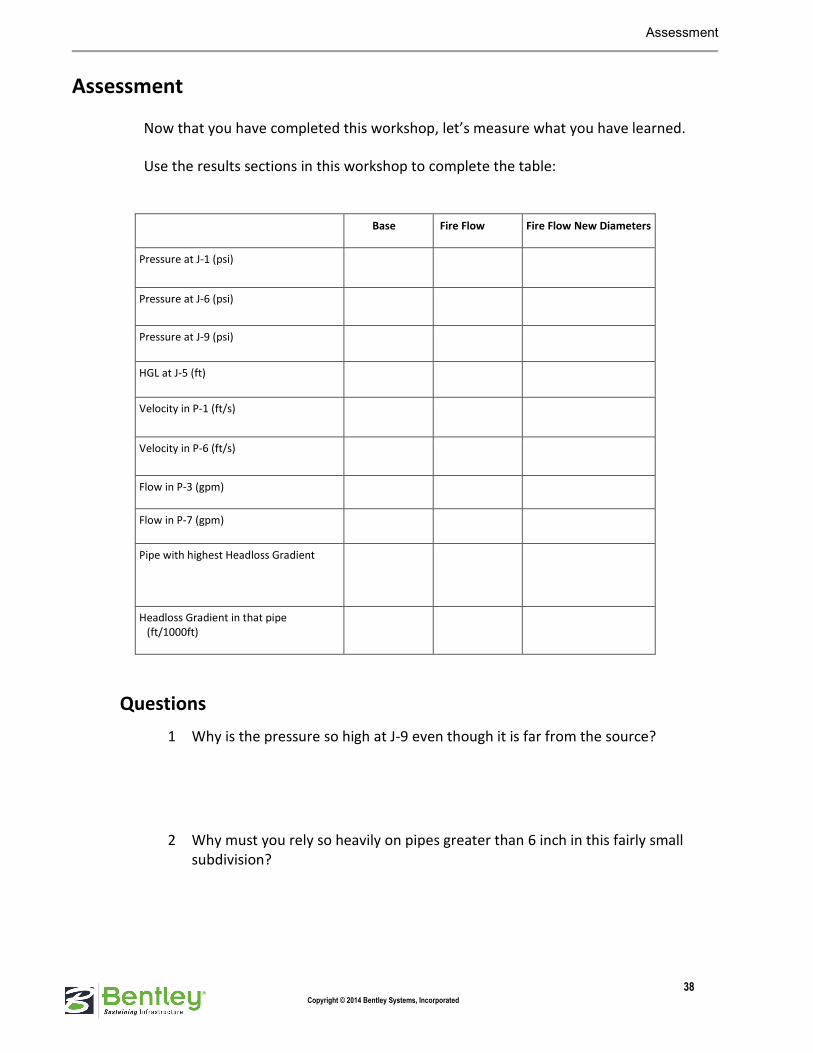
Assessment
Now that you have completed this workshop, let’s measure what you have learned.
Use the results sections in this workshop to complete the table:
Base Fire Flow Fire Flow New Diameters
Pressure at J-1 (psi)
Pressure at J-6 (psi)
Pressure at J-9 (psi)
HGL at J-5 (ft)
Velocity in P-1 (ft/s)
Velocity in P-6 (ft/s)
Flow in P-3 (gpm)
Flow in P-7 (gpm)
Pipe with highest Headloss Gradient
Headloss Gradient in that pipe
(ft/1000ft)
Questions
1 Why is the pressure so high at J-9 even though it is far from the source?
2 Why must you rely so heavily on pipes greater than 6 inch in this fairly small
subdivision?

Assessment
39 Copyright © 2014 Bentley Systems, Incorporated
3 What would really happen if you used the system from run 2 and had a fire at J-6
that needed 1000 gpm?
4 How does the split in flow between pipes 3 and 7 change as you change pipe
diameters? Why?
5 If another source of water were available along the highway at J-9, how might that
source affect the design?
6 What else could you do to help the pressures during normal demand periods?

Answer Key
40 Copyright © 2014 Bentley Systems, Incorporated
Answer Key
Base Fire Flow Fire Flow New Diameters
Pressure at J-1 (psi) 19 4.9 18
Pressure at J-6 (psi) 36 -22 25
Pressure at J-9 (psi) 75 34 68
HGL at J-5 (ft) 663 568 646
Velocity in P-1 (ft/s) 2 13 5
Velocity in P-6 (ft/s) 0.2 11 6
Flow in P-3 (gpm) 69 568 764
Flow in P-7 (gpm) 71 552 356
Pipe with highest Headloss Gradient P-1 P-1 P-5
Headloss Gradient in that pipe
(ft/1000ft)
2.4 75 15
* Some answers may vary between users due to the nature of this scaled model
1 Why is the pressure so high at J-9 even though it is far from the source?
It is located at the lowest elevation in the system.
2 Why must you rely so heavily on pipes greater than 6 inch in this fairly small
subdivision?
Streets are not laid out with water distribution in mind. More loops would
result in smaller pipes/greater reliability.
3 What would really happen if you used the system from run 2 and had a fire at J-6
that needed 1000 gpm?
You would not be able to get 1000 gpm. You would have lower flow with
higher pressures.
4 How does the split in flow between pipes P-3 and P-7 change as you change pipe
diameters? Why?
Initially they are the same but there is more flow through P-3 as it is increased.
5 If another source of water were available along the highway at J-9, how might that
source affect the design?
You might need to make P-10 larger so it would not be a bottleneck for the
future source.

Answer Key
41 Copyright © 2014 Bentley Systems, Incorporated
6 What else could you do to help the pressures during normal demand periods?
If possible:
• Put the tank at a higher elevation (higher static head)
• Operate the tank with more water in the tank (higher static head).
• Increase the system looping
• Add a fire pump to maintain adequate flow/pressure