designing a reliable and redundant network for multiple ...ieomsociety.org/dc2018/papers/167.pdf ·...
TRANSCRIPT

Proceedings of the International Conference on Industrial Engineering and Operations Management
Washington DC, USA, September 27-29, 2018
© IEOM Society International
Designing a reliable and redundant network for multiple
VLANs with Spanning Tree Protocol (STP) and Fast Hop
Redundancy Protocol (FHRP)
Faisal Shahriar1, MD. Shah Newaz2, Syed Zahidur Rashid3,Mohammad Azazur Rahman 4 and Muhammad Foyazur Rahman 5
International Islamic University Chittagong1234,University of North Carolina Charlotte5
Chittagong, Bangladesh1234,North Carolina, United States5
faisalshahriar9@gmail. com 1, shahnewazshaown@gmail. com2, szrashidcce@yahoo. com3,
ezaz. ctgbd3@gmail. com4, foyaz24@gmail. com5
Abstract
The demand for highly reliable and redundant network is increasing with the enormous spread of complex
network. But the complexity reduces the reliability of the network as failure of any device or link may cause
great harm to the network. To overcome these problems a network has been designed for multiple VLANs
with Spanning Tree Protocol (STP) and Fast Hop Redundancy Protocol (FHRP), where STP ensures Layer
2 redundancy and FHRP ensures Layer 3 redundancy. The performance of Spanning Tree Protocol (STP)
and three popular redundancy protocols of First Hop Redundancy Protocols (FHRP) includes Hot Standby
Router Protocol (HSRP), Virtual Router Redundancy Protocol (VRRP) and Gateway Load Balancing
Protocol (GLBP) have been observed. The results of the research implies that STP and FHRP is 100%
reliable for the network as there was no packet loss in case of device or link failure. HSRP consumes less
time than VRRP and GLBP. VRRP takes slightly less time than GLBP and it was the most stable.
Keywords
VLANs, STP, FHRP, HSRP, VRRP, GLBP, AVG, AVF.
1. Introduction:Redundancy of computer network means the process of duplication or installation of alternate network
device to retain the network functionality despite the failure of any device or path. It is highly desired but
not easily obtained at a maximum level. In order to obtain redundancy STP and FHRP were implemented
in network. The Spanning Tree Protocol (STP) provides network link redundancy so that a Layer 2 switched
network can recover from failures without intervention in a timely manner. The STP is defined in the IEEE
802.1D standard.[1] STP is developed to address the issue of loops and solve it. Fast Hop Redundancy
Protocol (FHRP) is a group of protocols that allow a router on a LAN network to automatically take over
if primary default gateway router fails. The three main First Hop Redundancy Protocols are HSRP, VRRP
and GLBP. [2]HSRP and GLBP are Cisco proprietary but VRRP is an IETF standard (RFC 3768). All the
protocols provides redundancy by setting one active or master router and others as standby or back up
routers. But GLBP is the only protocol that provides load balancing of traffic among the devices. The
research will be helpful for small and medium sized companies or institutes in implementing the best
network system by analyzing the outputs.
The operations and manageability of the FHRP was discussed in [2] for different network topologies. In
this research more in-depth analysis of the performances of the redundancy protocols are done on same
network. We have used STP as well as FHRP and a more reliable network is designed through our research.
A network was designed and simulated in [3] for internet service providers with high availability. We did
a better analysis and implemented the redundancy protocol in a more complex network with different
VLANs.
534

Proceedings of the International Conference on Industrial Engineering and Operations Management
Washington DC, USA, September 27-29, 2018
© IEOM Society International
To achieve highest redundancy for small and medium business companies with simple network a theoretical
analysis was done in [4]. The research paper discussed about different redundancy protocols and their
working procedures. In our research paper we have discussed about the redundancy protocols with
simulated results and analysis as well as the operation and management processes.
Research on FHRP was done by using IP Service Level Agreements (IPSLA) a Feature of Internetwork
Operating System (IOS) that allows to analyze the active traffic of IP service in [5]. It was a research for
simple network topology. Our research will satisfy the users and companies who has complex network
structure with STP and multiple VLANs as it shows more accurate analysis.
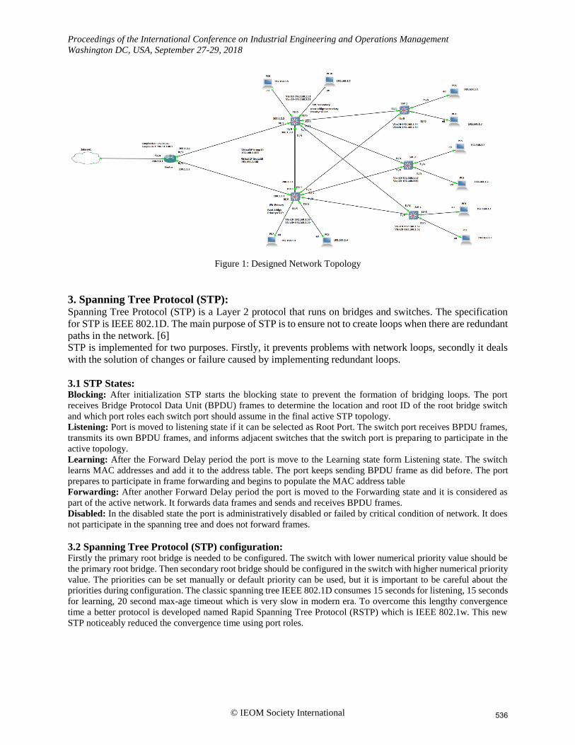
2. Network Architecture: The VLANs are created in all the switches. For this research we have created two VLANs (VLAN10 and
VLAN20) in each switch with 192.168.1.0 and 192.168.2.0 network. The default gateways are
192.168.1.100 and 192.168.2.100 respectively. More VLANs can be created if needed. We have used c3660
as switch which is a layer 3 device. Layer 2 switches can also be used where FHRP configuration is not
required as it is a Layer 3 redundancy protocol. Switches are interconnected in spanning tree network.
Trunking mode should be configured in the switch ports that are connected to other switches or
communication among VLANs will not be possible from switch to switch. Then redundancy protocol are
applied. For all three FHRP we configured 192.168.1.100 and 192.168.2.100 as virtual IPs for Group-10
and Group-20 which are the default gateways of the VLANs. Necessary routing protocols have to be
implemented for internet and other network access from the user devices.
Table 1: Configured IP addresses
Devices Interfaces IP Addresses Subnet Maks
Router FastEthernet 0/0
FastEthernet 0/1
FastEthernet 2/0
Loopback 0
Loopback 1
200.1.1.2
200.1.2.1
200.1.4.1
172.16.0.1
198.51.100.1
255.255.255.0
255.255.255.0
255.255.255.0
255.255.255.255
255.255.255.255
SW-Primary FastEthernet 0/0
FastEthernet 2/0
VLAN 10
VLAN 20
200.1.1.1
200.1.3.1
192.168.1.50
192.168.2.50
255.255.255.0
255.255.255.0
255.255.255.0
255.255.255.0
SW-Secondary FastEthernet 0/1
FastEthernet 2/0
VLAN 10
VLAN 20
200.1.2.2
200.1.3.2
192.168.1.51
192.168.2.51
255.255.255.0
255.255.255.0
255.255.255.0
255.255.255.0
SW-1 VLAN 10
VLAN 20
192.168.1.52
192.168.2.52
255.255.255.0
255.255.255.0
SW-2 VLAN 10
VLAN 20
192.168.1.53
192.168.2.53
255.255.255.0
255.255.255.0
SW-3 VLAN 10
VLAN 20
192.168.1.54
192.168.2.54
255.255.255.0
255.255.255.0
535
Proceedings of the International Conference on Industrial Engineering and Operations Management
Washington DC, USA, September 27-29, 2018
© IEOM Society International
Figure 1: Designed Network Topology
3. Spanning Tree Protocol (STP): Spanning Tree Protocol (STP) is a Layer 2 protocol that runs on bridges and switches. The specification
for STP is IEEE 802.1D. The main purpose of STP is to ensure not to create loops when there are redundant
paths in the network. [6]
STP is implemented for two purposes. Firstly, it prevents problems with network loops, secondly it deals
with the solution of changes or failure caused by implementing redundant loops.
3.1 STP States: Blocking: After initialization STP starts the blocking state to prevent the formation of bridging loops. The port
receives Bridge Protocol Data Unit (BPDU) frames to determine the location and root ID of the root bridge switch
and which port roles each switch port should assume in the final active STP topology.
Listening: Port is moved to listening state if it can be selected as Root Port. The switch port receives BPDU frames,
transmits its own BPDU frames, and informs adjacent switches that the switch port is preparing to participate in the
active topology.
Learning: After the Forward Delay period the port is move to the Learning state form Listening state. The switch
learns MAC addresses and add it to the address table. The port keeps sending BPDU frame as did before. The port
prepares to participate in frame forwarding and begins to populate the MAC address table
Forwarding: After another Forward Delay period the port is moved to the Forwarding state and it is considered as
part of the active network. It forwards data frames and sends and receives BPDU frames.
Disabled: In the disabled state the port is administratively disabled or failed by critical condition of network. It does
not participate in the spanning tree and does not forward frames.
3.2 Spanning Tree Protocol (STP) configuration: Firstly the primary root bridge is needed to be configured. The switch with lower numerical priority value should be
the primary root bridge. Then secondary root bridge should be configured in the switch with higher numerical priority
value. The priorities can be set manually or default priority can be used, but it is important to be careful about the
priorities during configuration. The classic spanning tree IEEE 802.1D consumes 15 seconds for listening, 15 seconds
for learning, 20 second max-age timeout which is very slow in modern era. To overcome this lengthy convergence
time a better protocol is developed named Rapid Spanning Tree Protocol (RSTP) which is IEEE 802.1w. This new
STP noticeably reduced the convergence time using port roles.
536
Proceedings of the International Conference on Industrial Engineering and Operations Management
Washington DC, USA, September 27-29, 2018
© IEOM Society International
4. Fast Hop Redundancy Protocol (FHRP): First Hop Redundancy Protocol is a computer networking based protocol which is designed to allow
gateway redundancy. It is implemented in a network to set a backup path if there is any disturbance
occurred. FHRP is configured by setting one active router and one or more standby router in the network.
A virtual IP is assigned in the process. There are several types of Fast Hop Redundancy Protocols such as
Hot Standby Router Protocol (HSRP), Virtual Router Redundancy Protocol (VRRP), Gateway Load
Balancing Protocol (GLBP), Common Address Redundancy Protocol (CARP), Extreme Standby Router
Protocol (ESRP), Routed Split multi-link Trunking (R-SMLT), NetScreen Redundancy Protocol
(NSRP).[7] In this paper we have analyzed the performance of three most used redundancy protocols which
are HSRP, VRRP, GLBP.
4.1 Hot Standby Router Protocol (HSRP): For the failure recovery in networks one of the redundancy protocols used is Hot Standby Router Protocol (HSRP). It
is a Cisco Proprietary. This protocol works between two or more devices. It creates a virtual gateway by setting a
virtual IP and MAC address between the configured devices & they act as a single device. HSRP virtual MAC in the
range 0000.0c07.acXX where the last 8 bits represent the standby group. The multicast group IP address for HSRP is
224.0.0.2 in version-1 and 224.0.0.102 in version-2. If any device is down or failed then the users will not face any
disturbance because another device will the take the responsibilities of the network. The default hello timer is 3
seconds, hold down timer is 10 seconds.
HSRP configuration: To configure HSRP an active router is needed to be set with higher priority. Priority is
configurable in the range of 1 to 255. Then the standby router is configured with a lower priority. Virtual IPs have to
be configured in both routers. The virtual IPs must be the exact same IPs that used as Default Gateways for every
VLAN groups. Decrement is set to decrease the priority of the active router if it is failed. When active router is down
then standby router act as an active router and after repairing the device it will act as active router again setting the
other device to standby mode. Preemption is configured to allow the standby router to delay to become active.
Advantages of HSRP: HSRP traffic is minimum. Configuration is very easy and most importantly it does not affect
the host configuration and routing configuration.[8]
Limitation: Security of HSRP is very poor. It does not support Load Balancing.
4.2 Virtual Router Redundancy Protocol (VRRP): Virtual Router Redundancy Protocol (VRRP) designed to eliminate the single point of failure in the static default
routing environment in VLANs. It’s an open standard protocol but not a Cisco Proprietary. VRRP is an IETF standard
(RFC 3768). VRRP operation is similar to HSRP with some difference. Unlike HSRP it can be implemented on
different vendors in Cisco and Non-Cisco environment.[9] It has the lowest convergence time of 3 seconds hold time
and 1 second hello time. Virtual MAC address for VRRP is 0000.5e00.01xx. The classic VRRP (RFC 3768) did not
support IPv6, but the latest version VRRPv3 (RFC 5798) now supports it. Multicast IP address for VRRP are
224.0.0.18 for IPV4 and FF02:0:0:0:0:0:0:12 for IPv6.
VRRP configuration: In VRRP a master router and one or more backup routers are configured. Master router is
configured with the highest priority and backup routers are configured with lower priority. Virtual IPs are configured
for each VLANs group. The virtual IPs must be the same IPs that configured as default gateways for the VLAN
groups. Preemption and decrement are configured which sets the Backup router as Master when the master router is
deactivated.
Advantages of VRRP: The convergence time of VRRP is lower than the other two protocols. It can be implemented
on different vendors.
Limitations: When there are multiple paths available, VRRP does not allow total use of network which is more
efficient. No security is provided in VRRP
537

Proceedings of the International Conference on Industrial Engineering and Operations Management
Washington DC, USA, September 27-29, 2018
© IEOM Society International
4.3 Gateway Load Balancing Protocol (GLBP): Gateway Load Balancing Protocol (GLBP) is a Cisco proprietary and acts like HSRP and VRRP with true load-
balancing capability. It sets an Active Virtual Gateway (AVG) for every configured group. The other groups will act
as backup path if AVG is failed. If there are more than two members the second best AVG will be in standby state
keeping all other devices in Listening state. The convergence time for GLBP is hello timer is 3 seconds, hold timer is
10 seconds. Multicast IP address is 224.0.0.102 and group virtual MAC address is 0007.b4xx.xxxx.
GLBP configuration: GLBP is configured as the previous two redundancy protocols by configuring One AVG
(Active Virtual Gateway) and up to 4 Active Virtual Forwarder (AVF) Routers on the group. In every physical
interface up to 1024 virtual router can be configured.[10] The virtual IPs must be the same as the Default Gateways
of the VLANs. Preemption is needed to be configured to set the standby routers into active state is the previous active
router is failed or deactivated.
Advantages of GLBP: Unlike previous two redundancy protocols we have discussed, GLBP can perform Load
Balancing which allows it to share the traffic load by multiple routers. In GLBP 1024 virtual routers can be configured
in a single physical interface. The authentication system is also better in GLBP. A simple authentication text password
can be configured between GLBP groups. Router with different authentication strings will be ignored by other
members even if they are in the same GLBP group.
Limitation: It’s a Cisco proprietary protocol. So it cannot be implemented in non-cisco devices.
5. Performance Analysis:
Table 2: Time consumption analysis of FHRP groups when no device is failed
Sample packet data HSRP
(Group 10)
Ms
HSRP
(Group 20)
ms
VRRP
(Group 10)
ms
VRRP
(Group 20)
ms
GLBP
(Group 10)
ms
GLBP
(Group 20)
ms
Sending data -1 47.125 46.123 30.580 19.552 93.590 46.123
Sending data -2 46.122 31.083 47.124 46.124 46.122 45.621
Sending data -3 46.625 124.330 108.789 46.122 45.623 45.621
Sending data -4 47.126 31.084 46.624 32.587 46.624 46.624
Sending data -5 46.624 78.207 93.750 46.624 46.432 125.333
Table 3: Time consumption analysis of FHRP groups when there is a device is failure
Sample packet data HSRP
(Group 10)
Ms
HSRP
(Group 20)
ms
VRRP
(Group 10)
ms
VRRP
(Group 20)
ms
GLBP
(Group 10)
ms
GLBP
(Group 20)
ms
Sending data -1 31.082 45.157 45.621 46.579 47.124 45.623
Sending data -2 78.208 46.589 47.126 62668 47.127 48.129
Sending data -3 47.126 46.658 47.089 47.058 45.624 46.624
Sending data -4 31.165 31.585 48.129 46.625 47.625 46.625
Sending data -5 46.599 46.168 47.628 46.623 47.623 45.621
Table 4 : Comparative table of average time consumption of FHRP groups between No Device failure and Device
Failure
HSRP
(Group 10)
Ms
HSRP
(Group 20)
ms
VRRP
(Group 10)
ms
VRRP
(Group 20)
ms
GLBP
(Group 10)
ms
GLBP
(Group 20)
ms
No Device Failure 47.7244 61.9654 65.3734 38.2018 55.6782 61.8644
Device Failure 46.836 43.2314 47.1186 49.9106 47.0246 46.5244
538

Proceedings of the International Conference on Industrial Engineering and Operations Management
Washington DC, USA, September 27-29, 2018
© IEOM Society International
Figure 2: Graphical analysis of average time consumption of FHRP groups for No Device failure and Device Failure
6. Conclusion: After the in-depth analysis of the research we have come to the conclusion that redundancy protocol made
the topology more reliable and redundant. The failure of any device does not affect network.
Communication among the users of same VLAN remain unharmed. From the analysis of FHRP
performance we came to and understanding that every protocol has some benefits and drawbacks. The study
implies that VRRP time consumption is very unstable when there is no device failure. But GLBP consumed
slightly more time on average than other two protocols. On the other hand when there was device failure
GLBP acted fast and the time consumption of GLBP in that case was almost same as HSRP. VRRP in case
of device failure consumed most time.
References
Bharathidasan, A.R, Yuvaraj, M, Premnath, G, Comparative Study on Spanning Tree Protocol and Trust Based
Routing Protocol, International Journal of Computer Science Engineering and Technology, Vol 4, pp. 349-352, Issue
12 , Dec 2014
Dubey, Priyanka, Sharma, Shilpi, Sachdev, Aabha, Review of First Hop Redundancy Protocol and Their
Functionalities, International Journal of Engineering Trends and Technology, Volume 4, pp. 1085-1088 Issue 5- May
2013
Mahdi Abdullah, Jameel, Hussain, Anas Ali, Simulation of High Availability Internet Service Provider’s Network,
Iraqi Journal of Computers,Communications,Control and Systems Engineering, Vol.13, No.1, pp. 18-31, 2013
Papić, Silvio, Achieving Optimal Redundancy in a Small Business Network, International Journal of DIGITAL
TECHNOLOGY & ECONOMY, Volume 1 pp. 13-23, Issue- Number 1 2016
Ibrahimi, Mohammad Hamid, Vora, Komil B, Khimani, Kunal, Deploy Redundancy of Internet using First Hop
Redundancy Protocol and Monitoring it using IP Service Level Agreements (IPSLA), International Journal of
Engineering Science and Computing, Volume 7,pp. 15320-15322, Issue No.10, October 2017
47.7244
61.9654 65.3734
38.2018
55.678261.8644
46.83643.2314
47.1186
49.9106
47.0246 46.5244
0
10
20
30
40
50
60
70
(Group 10) (Group 20) (Group 10) (Group 20) (Group 10) (Group 20)
HSRP HSRP VRRP VRRP GLBP GLBP
TIm
e (m
s)
FHRP Groups
No device Failure
Device Failure
539

Proceedings of the International Conference on Industrial Engineering and Operations Management
Washington DC, USA, September 27-29, 2018
© IEOM Society International
Understanding and Configuring Spanning Tree Protocol (STP) on Catalyst Switches, Available:
https://www.cisco.com/c/en/us/support/docs/lan-switching/spanning-tree-protocol/5234-5.html.
Category:First-hop redundancy protocols, Available: https://en.wikipedia.org/wiki/Category:First-hop_redundancy_protocols.
Ravikumar, C. V., Srikanth, Y. M., Sairam, P., Sundeep, M., Bagadi, Kala Praveen, Annepu, Visalakshi, Performance
Analysis of HSRP in Provisioning Layer-3 Gateway Redundancy for Corporate Networks, Indian Journals of Science
and Technology, Vol 9(20), DOI: 10.17485/ijst/2016/v9i20/89851, May 2016.
Bhagat, Nikhil Hemant, Virtual Router Redundancy Protocol-A Best Open Standard Protocol in Maintaining
Redundancy, International Journal of Computer Applications, 2011.
Yu, Betsy, What the Main Difference between HSRP, VRRP and GLBP Protocols, Available:
http://blog.router-switch.com/2012/12/what-the-main-difference-between-hsrp-vrrp-and-glbp-protocols/.
Biographies
Faisal Shahriar is pursuing B.Sc. in Electronic and Telecommunication Engineering at International Islamic
University Chittagong, Bangladesh. His research interests includes Computer Networking, Optical Fiber
Communication, Long-Term Evolution (LTE) etc.
MD. Shah Newaz is pursuing B.Sc. in Electronic and Telecommunication Engineering at International Islamic
University Chittagong, Bangladesh. His research interest is Computer Networking.
Syed Zahidur Rashid is serving as an Assistant Professor in the department of Electronic and Telecommunication
Engineering, International Islamic University Chittagong, Bangladesh. His research interests include Computer
Networks, Signal and Image Processing, Neural Networks etc.
Mohammad Azazur Rahman is pursuing B.Sc. in Electronic and Telecommunication Engineering at International
Islamic University Chittagong, Bangladesh. He has completed three research projects. His research interests include
Power Line Communication and Computer Networking.
Muhammad Foyazur Rahman received the B.Sc. Degree in electrical and electronic engineering from American
International University Bangladesh (AIUB), Bangladesh, in 2011, and M.Sc. degree in electrical engineering from
Lamar University, USA in 2017. He is currently working towards his Ph.D. degree at University of North Carolina
Charlotte, USA. He worked as a Lecturer in the Department of Electrical and Electronics Engineering at Atish
Dipankar University of Science and Technology for two years. He is currently a Research Assistant in the Department
of Electrical and Computer Engineering, University of North Carolina Charlotte. His research interests include power
electronic converters, wide band gap switches and computer networking.
540