designing a human powered vehicle team #20 needs assesment
TRANSCRIPT

Team20 i
2018
Designing a Human Powered Vehicle
Team #20 Needs Assesment
Team Members Contact Email
Peyton Lanier
Brady Bauer
Miguel Rodriguez
Edward Bohne
Genevieve Macdonnell
Faculty Advisor: Mr. Keith Larson
Sponsor: Florida Space
Instructors: Dr. Shane McConomy
Submitted: 9/27/17
11/2/2017
Team20 ii
2018
Abstract
The Needs Assessment Report lays out the requirements needed to compete in the ASME
Human Powered Vehicle Competition. The competition requires many safety features such as a
maximum braking distance and turn radius and a minimum amount of force to withstand. It will
also require a Design and Innovation paper that will need to be submitted prior to the
competition to show case our design and the innovative things such as the Hans Cycle that will
be implemented into the design.

Team20 iii
2018
Table of Contents
Abstract ............................................................................................................................... ii
Disclaimer .......................................................................... Error! Bookmark not defined.
Acknowledgement ............................................................. Error! Bookmark not defined.
List of Tables ...................................................................................................................... v
List of Figures .................................................................................................................... vi
Chapter One: EML 4551C .................................................................................................. 1
1.1 Project Scope ............................................................................................................ 1
1.2 Customer Needs ........................................................................................................ 1
1.3 Functional Decomposition ........................................................................................ 3
1.4 Target Summary........................................................................................................ 4
1.5 Concept Generation .................................................................................................. 6
System 1. Aerodynamics ........................................................................................... 8
System 2. Drivetrain ................................................................................................... 9
System 3. Frame/Roll Protection ............................................................................. 12
System 4. Steering .................................................................................................... 13
System 5. Energy Storage ......................................................................................... 15
Appendix A: Code of Conduct ........................................................................................ A1
Appendix B: Functional Decomposition .......................................................................... B1

Team20 iv
2018
Appendix C: Target Catalog ............................................................................................. C1
References ........................................................................................................................ D1

Team20 v
2018
List of Tables
Table 1 Break Down of Concepts ...................................... Error! Bookmark not defined.

Team20 vi
2018
List of Figures
Figure 1. Calculations for Tire Size. ................................................................................... 4
Figure 2. Tadpole Trike Configuration. .............................................................................. 6
Figure 3. Bicycle Configuration. ........................................................................................ 7
Figure 4. Hans Cycle......................................................................................................... 10
Figure 5. Frame. ................................................................................................................ 12
Figure 6. Linkage. ............................................................................................................. 13
Figure 7. Bicycle Handle Bar. ........................................................................................... 14
Figure 8. Steering Rack..................................................................................................... 15

Team20 1
2018
Chapter One: EML 4551C
1.1 Project Scope
The Human Powered Vehicle Challenge is an ASME competition in which students
design and build an eco-friendly, fast, and safe mode of transportation. The goals of the project
are to achieve top marks in the Design and Innovation challenges at the Official ASME HPVC.
The team will build a prototype and attempt to obtain a high ranking in the racing portion of the
competition as well. The main market for this human power vehicle is mega cities where
alternative solutions for current highway vehicles are needed. The team will produce a prototype
for the competition and assuming time and budget allows, will produce a fully functional vehicle.
1.2 Customer Needs
Knowing that our project is a competition, the rules in the competition are spelled out
very strictly and we need to adhere to them. After meeting with Dr. McConomy, we decided that
that we need to focus on 3 specific aspects of the challenge; Design Challenge, Innovation
Challenge and Women's Speed Challenge. Each of these challenges have to follow the following
main rules and guidelines for the event which are shown below.
The requirements of the American Society of Mechanical Engineering's Human Powered
Vehicle Challenge are as follows:
• Roll protection system capable of withstanding specified top and side loads indicated in
the 2018 HPVC Rules document.

Team20 2
2018
• Roll protection system that is structurally attached and braced to the vehicle frame or
fairing.
• Rigidly mounted and structurally sound seat and properly affixed safety harness.
• Safety harnesses attached to the RPS or a structural member in the RPS and may not be
attached to the seat unless it is structurally integrated into the RPS.
• Come to a stop from a speed of 25 km/hr in 6.0 m (19.7 ft)
• Turn radius within an 8.0m (26.2 ft)
• Capability of driving for 30 m (98.4 ft) in a straight line at a speed of 5 to 8 km/hr
• Braking system with properly designed brakes on the front most wheel of the vehicle at a
minimum; must have at least front wheel brakes (if more than 1 front wheel)
• Appropriate guards fitted for all drivetrain components, steering components, and wheels
if within reach of the rider and must be designed and constructed so that they will not
injure the rider in the event of an accident.
• Properly fitting helmets with fastened straps that meet CPSC Safety Standard for bicycle
helmets (16 CFR Part 1203)
• Forward-facing field of view of at least 180° wide for the driver.
• Submit a short video (maximum 2 minutes) showing their HPVs completing the three
performance safety requirement tests (Section III.B). Video files must be less than
500MB, in mp4 format, and submitted at least one week before the race.
• Written report, technical presentation, and performance safety video for the vehicle

Team20 3
2018
Our team feels that these points below should be implemented in the project:
• Be compact
• Design and demonstrate technical innovation related to their vehicle.
• Display school name or initials on each side of the vehicle in characters at least 10 cm
high in a color that contrasts with the background
After discussing with Dr. McConomy, we feel that it would be nice to:
• Win the challenges
• Utilize ultracapacitors
• Incorporate a CVT
1.3 Functional Decomposition
The human powered vehicle’s functions are to:
• Use human input to create mechanical energy
• Transport operator by rolling on wheels
• Transport operator safely
• Enable operator to travel on government maintained roads
• Enable operator to steer vehicle in desired direction
• Enable operator to detect upcoming obstacles
• Enable operator to alter vehicle’s longitudinal acceleration

Team20 4
2018
1.4 Target Summary
The targets of the Human Powered Vehicle are made up of velocities, accelerations and
decelerations, and numbers of components. Some of the targets were found from benchmarking
other human powered vehicles as well as from the official ASME HPVC rules. The first target is
to use human input to create mechanical energy. The rules of the competition are that the vehicle
must use only human power to propel the vehicle down a track. The human input should be able
to pedal the vehicle at least 142.8 RPMs to get the vehicle to 40mph. To achieve this speed, we
will use a gear ratio of 3.25:1 on the standard bicycle gear train that can be implemented in this
vehicle. The calculations are shown in the table below:
Target Speed (mph)
Speed (ft/s)
Tire Diameter (in)
Tire Diameter (ft)
Tire circumference (ft)
Tire angular velocity (rev/s)
Max Gear Ratio
Input angular velocity (rev/s)
40 58.67 29 2.42 7.59 7.73 3.25 2.38
Vehicle operator would have to pedal
2.38 revolutions per second to achieve
40 mph
Figure 1. Calculations for the Tire Size
The second target is to transport the operator on rolling wheels. We have this target so
that the vehicle can be used to move the driver from one place to another. This will be done
using 700c bike tires. Which equate out to 29 inches in diameter, as shown in the speed
calculation table above. We will aim to use at least 2 wheels but no more than 4 total.
The following targets are designated to keeping the operator of the vehicle safe, to be
able to maneuver it adequately and to be able to operate the vehicle on government maintained
Team20 5
2018
roads. This is because, if the vehicle is ever actually marketed to the public, these are important
for both appealing to customers as well as getting the permits needed for production. This is
done by being able to stop the vehicle from 25km/hr in less than 6 meters. Having a Roll
Protection System in place is also going to keep the operator safe and must withstand a top load
and side load of 2630 N and 1330 N respectively. Maneuvering the vehicle should come with
ease and it should have a turn radius of less than 24.6ft, while the operator has at least a 180-
degree field of view.
Team20 6
2018
1.5 Concept Generation
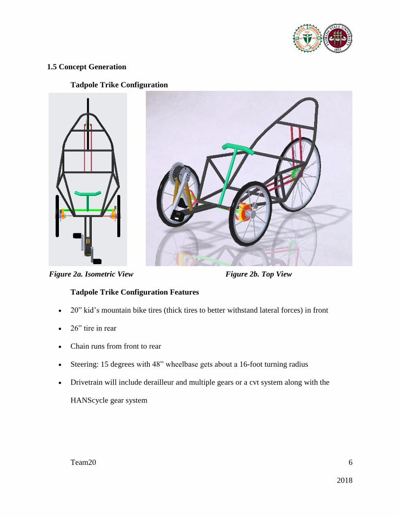
Tadpole Trike Configuration
Figure 2a. Isometric View Figure 2b. Top View
Tadpole Trike Configuration Features
• 20” kid’s mountain bike tires (thick tires to better withstand lateral forces) in front
• 26” tire in rear
• Chain runs from front to rear
• Steering: 15 degrees with 48” wheelbase gets about a 16-foot turning radius
• Drivetrain will include derailleur and multiple gears or a cvt system along with the
HANScycle gear system

Team20 7
2018
• Steering involves a linkage still to be determined; two configurations include laterally
moving steering wheel to rotate wheels or a linkage or steering rack that rotates wheels
when the steering wheel is rotated
• RPS completely protects driver during operation and protects them in both the vertical
load and side load crash conditions
• Brakes rotors and calipers are located on both front wheels of the vehicle
Bicycle Configuration
Figure 3. Bicycle Configuration
• Large 29” wheel in the rear for more speed at same rpm.
• Chain runs from front to rear
• Very low and skinny orientation of the driver
• Steering: The ability to lean into the turn will reduce the chance of flipping and will allow
for less turning from the handle bars. The steering will be exactly like a normal bicycle.

Team20 8
2018
• Roll protection system will be made from the back rest of the vehicle. A roll cage will be
made from a bar above the driver and a bar on each side of the driver.
• Brakes rotors and calipers are located on the front wheel of the vehicle
Table 1.
Breakdown of Concepts from each subsection.
System Concepts
Aerodynamics Full Fairing
Aerodynamics Small Fairing
Aerodynamics No Fairing
Drivetrain Chain
Drivetrain Rubber Belt
Drivetrain Full Rotating Petals
Drivetrain HANScycle
Drivetrain Gear
Drivetrain CVT
Drivetrain 2 Wheel
Drivetrain 3 Wheel
Drivetrain Variable Wheel
Frame/Roll Protection System Frame
Steering Linkage
Steering Bicycle Handlebar
Steering Steering Rack
Energy Storage Ultracapacitor
System 1. Aerodynamics
Full Fairing
A full fairing would be used to compensate for the air resistance caused by a non-
streamlined design.

Team20 9
2018
Small Fairing
A small fairing would be used as a windshield for the driver rather than for aerodynamic
purposes. The fairing would help for rain avoidance.
No Fairing
A fairing would not be necessary if the increase in weight because of adding the fairing
outweighs the aerodynamic benefit of having one. In other words, the addition of a fairing will
increase the overall weight of the vehicle and therefore the force of friction acting on the tires
would slow us down.
System 2. Drivetrain
Chain
A chain will provide an efficient and durable method of transferring human input into
mechanical energy. Although a chain has very tight tolerances when installing, it can be repaired
easily after it fails.
Rubber Belts
A rubber belt functions similarly to a chain; however, the rubber belt has a significantly
greater tolerance and cannot be fixed once it fails.
Full Rotation Pedals
Full rotation pedals allow the user to pedal in a circular motion to convert their energy
into mechanical energy and can be found on most bicycles.
Team20 10
2018
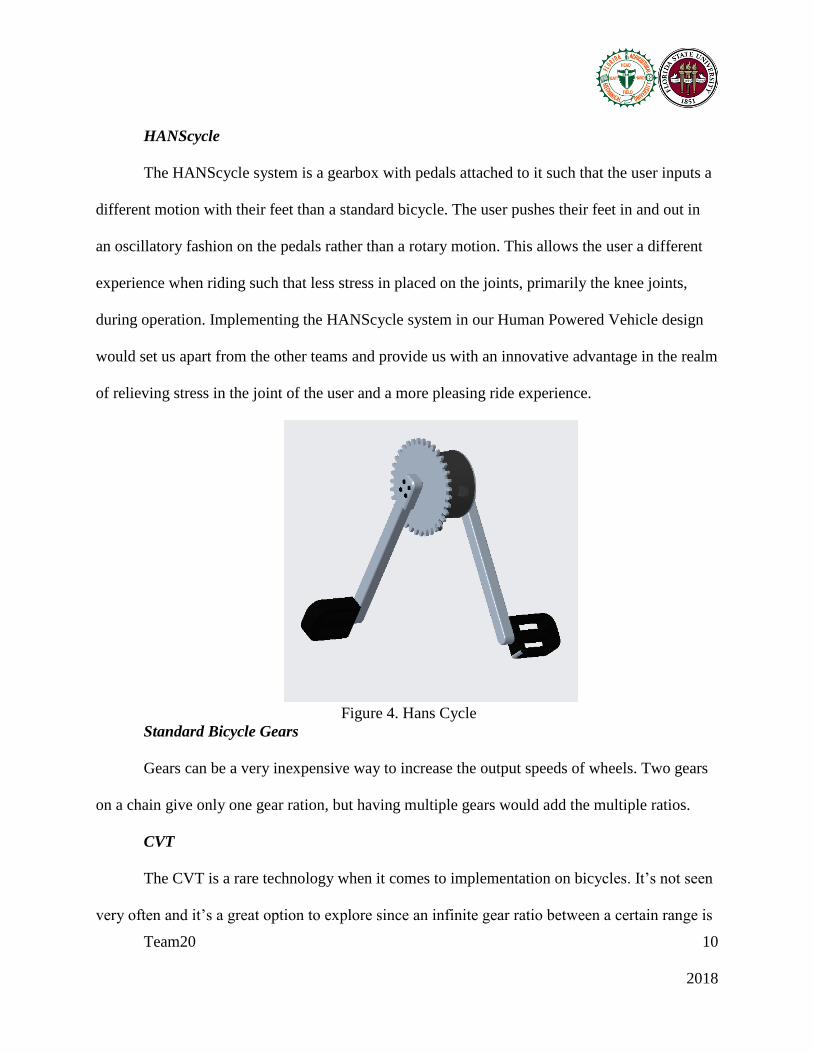
HANScycle
The HANScycle system is a gearbox with pedals attached to it such that the user inputs a
different motion with their feet than a standard bicycle. The user pushes their feet in and out in
an oscillatory fashion on the pedals rather than a rotary motion. This allows the user a different
experience when riding such that less stress in placed on the joints, primarily the knee joints,
during operation. Implementing the HANScycle system in our Human Powered Vehicle design
would set us apart from the other teams and provide us with an innovative advantage in the realm
of relieving stress in the joint of the user and a more pleasing ride experience.
Figure 4. Hans Cycle
Standard Bicycle Gears
Gears can be a very inexpensive way to increase the output speeds of wheels. Two gears
on a chain give only one gear ration, but having multiple gears would add the multiple ratios.
CVT
The CVT is a rare technology when it comes to implementation on bicycles. It’s not seen
very often and it’s a great option to explore since an infinite gear ratio between a certain range is

Team20 11
2018
available, giving the operator of the vehicle efficient acceleration capabilities. It can also make
the acceleration process swifter as opposed to shifting through many different gear ratios as with
a standard bicycle, giving us an advantage when it comes to accelerating.
2 Wheel
A two-wheeled vehicle would be utilized to reduce the weight and size of the
vehicle. The vehicle would be made skinnier than a vehicle with more wheels, therefore it would
have a smaller frontal area and make it more aerodynamic. This vehicle would also have less
material, which would reduce the weight allowing it to travel faster. Two wheels would make it
harder for the vehicle to flip in a turn because it could lean into also make it.
3 Wheel
A three-wheeled vehicle would be more stable than a two wheeled. The driver wouldn’t
have to worry about balance when coming to a stop or going slow threw turns.
Variable Wheel Size
The main reason for using a wheel that can change its size would be to change the
moment of inertia of the wheel. A small wheel would have a small moment of inertia and would
be easier to rotate. As the speed increases, the wheel size could manually be increased to allow
for more distance per revolution of the wheel. The small wheel size would be great for
acceleration while the large wheel size would be great for getting a higher top speed.

Team20 12
2018
System 3. Frame/Roll Protection
Frame
The frame needs to be made very safe so the driver won’t injure themselves. The frame
will have a roll protection system such as a roll cage to protect the driver in the case of a crash or
rollover.
Figure 5. Frame CAD
Team20 13
2018
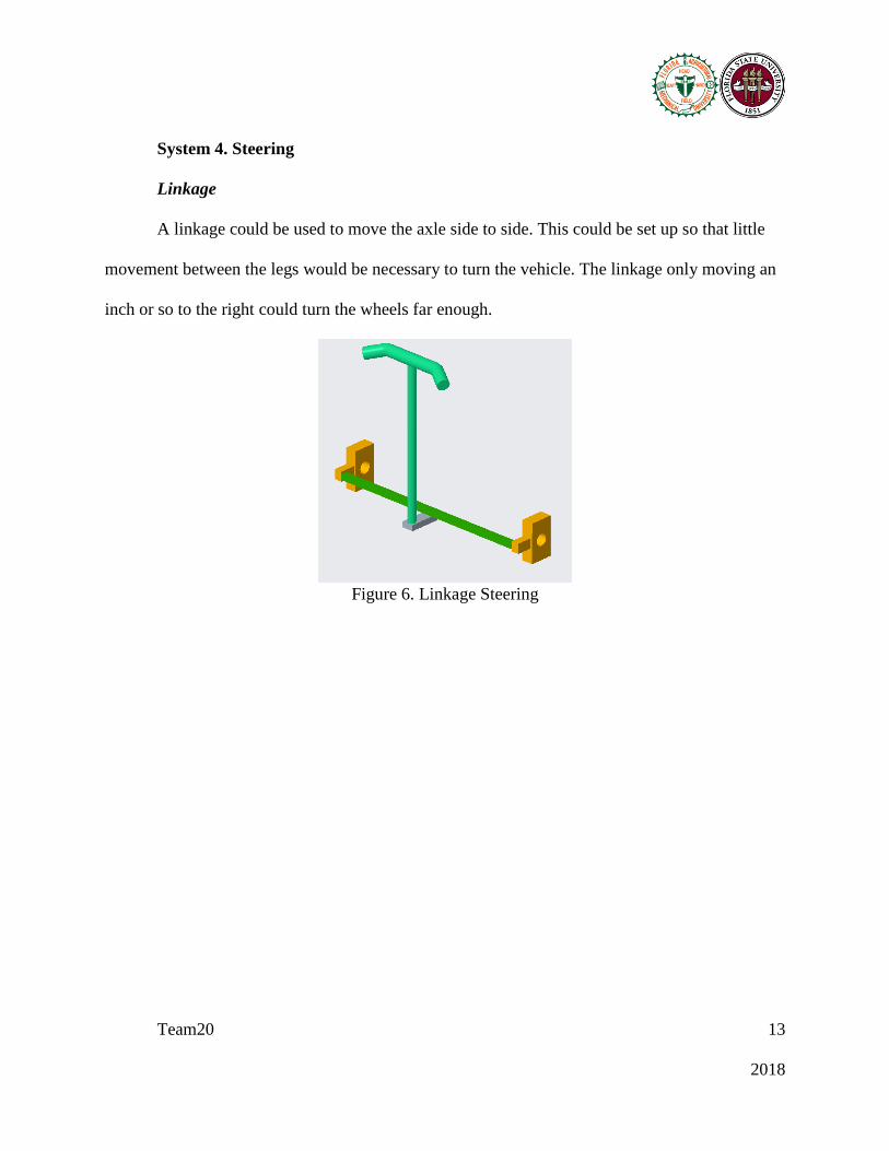
System 4. Steering
Linkage
A linkage could be used to move the axle side to side. This could be set up so that little
movement between the legs would be necessary to turn the vehicle. The linkage only moving an
inch or so to the right could turn the wheels far enough.
Figure 6. Linkage Steering

Team20 14
2018
Bicycle Handlebar
The traditional bicycle handlebar is a compact and easy steering system to implement. It
uses a one simple pin joint to rotate the tire.
Figure 7. Bicycle Handlebar

Team20 15
2018
Steering Rack
A steering rack system could combine the bicycle and linkage system by having an axis
that turns the wheel hubs and has a handle bar that rotates in a pin joint. A rack and pinion gear
set is used to change the rotational movement into linear movement of the axis side to side.
Figure 8. Steering Rack
System 5. Energy Storage
Ultracapacitors
These would be utilized to harness energy while operating the vehicle and use it later
during situations where faster acceleration or max speed is desirable. Integration would involve
placement near the pedals of the vehicle and the motion of the pedals would help create electrical
energy within the ultra-capacitor.

Team20 A1
2018
Appendix A: Code of Conduct
Table of Contents
Mission Statement…………………………………………………………………………….. 1
Roles…………………………………………………………………………………………… 1
Team Leader…………………………………………………………………………… 1
Treasurer……….……………………………………………………………………… 1
Scribe………………………………………………………………………………….. 2
Design and Analysis Lead…………………………………………………………….. 2
All Team Members……………………………………………………………………. 2
Communication………………………………………………………………………………. 3
Team Dynamics………………………………………………………………………………. 3
Ethics…………………………………………………………………………………………. 4
Dress Code……………………………………………………………………………………. 4
Weekly and biweekly Tasks…………………………………………………………………… 4
Decision Making……………………………………………………………………………… 4
Conflict Resolution…………………………………………………………………………… 5
Statement of Understanding…………………..………………………………………………. 5

Team20 A2
2018
Mission Statement
Team 21 is dedicated to making safe, ethical and thought-out decisions when performing
engineering tasks. Anything produced by the team is intended to relay engineering knowledge
and innovative ideas to the engineering community. Time management, teamwork, and
discipline will allow the team to meet deadlines and efficiently create engineering designs,
analyses and products.
Roles
Team Leader
The team leader will be the main point of contact for our team. They shall keep the team
working in unity. If a problem in the team should arise, the team leader will keep the integrity of
the project intact. The team leader will be the mediator in case of untimely indecision.
The team leader will be in charge of delegating tasks to members best suited for the job
based on that team members strengths. Team leader will be responsible for keeping positivity
among the group and act in the best interest of the project. They will develop a timeline for the
project and use organizational skills to make plans come to life in a timely manner.
Financial Manager
The treasurer will be in charge of organizing finances for Team 21 and for the Human
Powered Vehicle competition. The treasurers are responsible for reviewing all requests for
purchases in order to decide whether the product is necessary or could be substituted. If the
purchase is necessary, the treasurers will order the product and add the cost to their budget
records.

Team20 A3
2018
Scribe
The scribe will be in charge of keeping minutes of every meeting as well as keeping track
of where the team left off at previous meetings. In addition, the scribe will be responsible for
keeping track of who attends meeting as well as send out emails containing their notes.
Design and Analysis Lead
The design and analysis lead will be in charge of leading efforts regarding designing and
performing analyses for the vehicle. Consulting with school faculty will also be sought out
regarding the validity and effectiveness of said analyses and designs.
All Team Members
All team members will communicate effectively while respecting others’ roles and ideas.
Additionally, team members will be assigned different projects and are expected to keep all
commitments and deliver them before the designated due date. Members will be expected to treat
all parts of the project with respect and commitment. Members will respect others’ feedback of
their portions of the project and will be respectful in giving feedback. Every person is expected
to be an ambassador to the outside world for their own portions of the project and report back to
the team at weekly meetings. Team members will show confidence in our team when any and all
occasions to do so arise.

Team20 A4
2018
Communication
The team will have most of its communication in the meetings. If there are urgent matters
that cannot wait until a meeting, there is a GroupMe group chat setup to allow for messaging us.
The documents that are being made by the team will be stored on Google Drive which will
eliminate the need for emailing them.
If a meeting time will need to be changed, the message must be sent out more than 4
hours before the meeting is supposed to start. If a meeting needs to be added, the message
should be sent out 24 hours in advance. If a member cannot make it to a meeting, they need to
let the team know 4 hours in advance. Multiple absences will result is meeting time changes and
further absences will not be tolerated.
Team Dynamics
All members of our team are equal; every person’s opinion will be not only considered
but done so thoughtfully when it comes to every decision; each member of the team will keep all
commitments by the due date; each member agrees to assess whether all members are honoring
their commitments to the team. All communication between team members will be respectful;
No team member will talk down to another; Team members will recognize contributions
positively.
Ethics
The team members should practice the NSPE Engineering Code of ethics. Each team
member must complete all work assigned to them and try to go above and beyond to help the rest
of the team. Always keeping ethical practices in mind will allow the team to be successful.

Team20 A5
2018
Dress Code
Team meetings can be held in any socially appropriate attire. Sponsor meetings and
group presentations will be held in business casual or formal dress that will depend on the event.
Weekly and Biweekly Tasks
There will be meetings held every Monday and Wednesday from 12:00 PM to 2:00 PM is
a reserved conference room at the COE. If more meeting time is needed during the week, the
team will use the unused time from Senior Design Class. If there are too many or not enough
meeting times, the team will vote on how to change them. Meeting minutes will be taken by the
team note taker.
Each week the team needs to make journal entry that explains everything that was
accomplished that week and everything that needs attention the week coming up. At Least every
other week, the sponsor/advisor will be updated on the team's progress.
Decision Making
All ideas and opinions will be taken into consideration during the decision making
process. Members will make decisions by consensus, but majority rule will be used if a
consensus can not be made in a timely manner; any and all conflicts will be resolved with the
persons involved directly.
Conflict Resolution
All team members will make certain they have agreed on what and when to
communicate; complaints about fellow team members will be addresses within the team first.

Team20 A6
2018
If a conflict cannot be resolved within the team, Professor McConomy will be contacted to help
resolve it.
Statement of Understanding
By signing this document the members of Team 21 agree the all of the above and will
abide by the code of conduct set forth by the group.

Team20 B1
2018
Appendix B: Functional Decomposition
The human powered vehicle’s functions are to:
• Use human input to create mechanical energy
• Transport operator by rolling on wheels
• Transport operator safely
• Enable operator to travel on government maintained roads
• Enable operator to steer vehicle in desired direction
• Enable operator to detect upcoming obstacles
• Enable operator to alter vehicle’s longitudinal acceleration

Team20 C1
2018
Appendix C: Target Catalog
1. Use human input to create mechanical energy
a. How many RPMs?
i. 600 RPMs
b. What gear ratio if no CVT is used?
i. 3.25:1 (standard bicycle gear train)
c. What gear ratio can the CVT provide?
i. 4.8:1 (NuVinci CVT)
2. Transport operator by rolling on wheels
a. What size wheels?
i. 700c (29”)
b. How many wheels?
i. 2
ii. 3
iii. 4
3. Transport operator safely
a. How many meters does it take to stop it?
i. <6 m from 25 km/hr
b. How stable must the vehicle be while traveling?
i. Must travel for 30 m (98.4 ft) in a straight line at a speed of 5 to 8 km/hr (fast
paced walking speed).
c. What kind of RPS (single post, or bar over head)?
i. What kind of loads does it need to handle?
1. (Single or bar) top load of at least 601 lbs (2670 N)
2. (Single or bar) side load of at least 299 lbs (1330 N)
ii. How will operator be secured in vehicle?
1. Shoulder harness
iii. How is driver positioned?
1. Recumbent
iv. How is the vehicle able to adapt to different sized riders?
i. Seat adjustment

Team20 C2
2018
4. Enable operator to travel on government maintained roads
a. Does it need lights, if so how many?
i. >300 lumen white headlight
ii. >10 lumen red taillight
b. Does it need reflective material, if so how much?
i. No reflective material required
5. Enable operator to steer vehicle in desired direction
a. Turning radius
i. 24.6 ft turn radius
6. Enable operator to alter vehicle’s longitudinal acceleration
a. How many wheels have brakes?
i. One brake per wheel on front most wheels
7. Enable operator to detect upcoming obstacles
a. Field of view angle?
i. >180 degrees

Team20 D1
2018
References
There are no sources in the current document.