designing a high resolution fiber-fed spectrograph for solar observations edmond wilson brennan...
TRANSCRIPT

Designing a High Resolution Fiber-Fed Spectrograph for Solar Observations
Edmond WilsonBrennan ThomasonStephanie Inabnet
Tamara ReedHarding University
Project Goal
Design a spreadsheet program to aid in optimizing the light throughput of a Czerny-Turner Spectrograph fed by an optical fiber

Czerny-Turner Monochromator Configuration
http://terpconnect.umd.edu/~toh/models/Monochromator.png

The model for our instrument is based on the discussion in Chapter 1 of the book, Guide for Spectroscopy, by Jobin Yvon/SPEX, 1994. Figure 1 below was created from Figure 3 in the book, with errors in the original figure corrected. Although the light path of a Czerny-Turner spectrometer is usually folded, mathematically, it can be treated as if the light path were arranged linearly without changing the results.
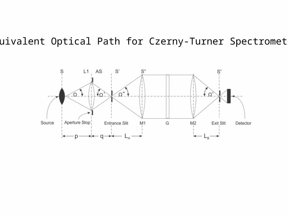
Equivalent Optical Path for Czerny-Turner Spectrometer


Begin with a grating….
Plane Grating Dimensions Richardson Grating Laboratories, Grating Model Number 290-R GivenEnter Diffraction Order to Be Used in Calculations, k 1 Given
Enter height of grating in mm, hG 58 Given
Enter width of grating in mm, wG 58 GivenEnter thickness of grating in mm & inches 6 GivenEnter groove density of grating in grooves/mm, n 1800 GivenEnter Blaze wavelength in Littrow configuration in nm 500 GivenEnter Nominal blaze angle in degrees 26.7 Given
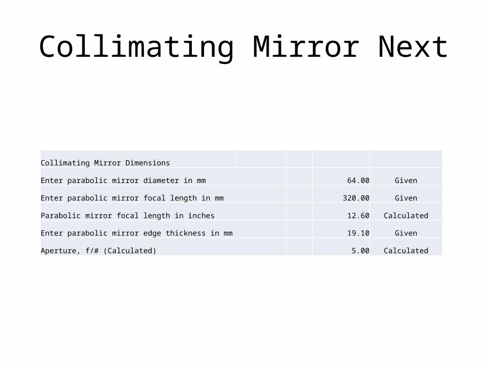
Collimating Mirror Next
Collimating Mirror Dimensions
Enter parabolic mirror diameter in mm 64.00 Given
Enter parabolic mirror focal length in mm 320.00 Given
Parabolic mirror focal length in inches 12.60 Calculated
Enter parabolic mirror edge thickness in mm 19.10 Given
Aperture, f/# (Calculated) 5.00 Calculated
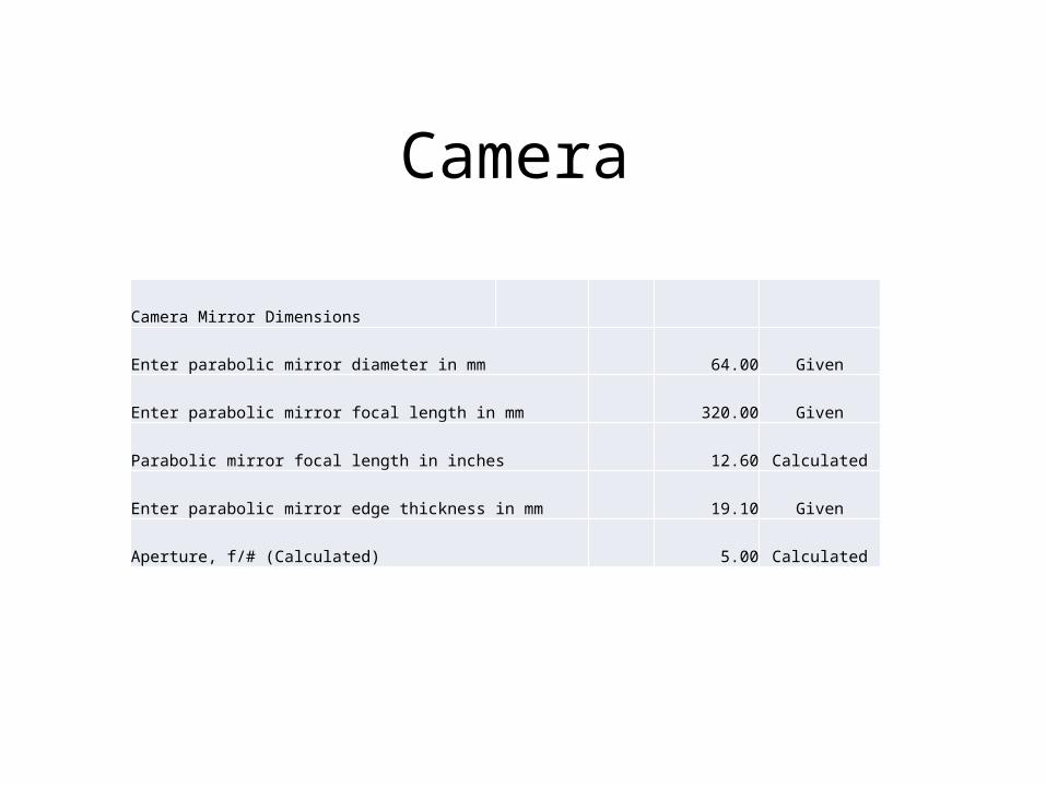
Camera
Camera Mirror Dimensions
Enter parabolic mirror diameter in mm 64.00 Given
Enter parabolic mirror focal length in mm 320.00 Given
Parabolic mirror focal length in inches 12.60 Calculated
Enter parabolic mirror edge thickness in mm 19.10 Given
Aperture, f/# (Calculated) 5.00 Calculated

Slit Parameters
Slit Dimensions
Enter Fixed Slit Height in mm, h 0.2987 Given
Enter Fixed Slit Width in µm, w =bandpass/dispersion, mm 15 Given
Spectral Bandpass desired, nm 0.5

Fiber Parameters
Fiber Parameters
Enter the diameter of the fiber in µm 1000 Given
Enter numerical aperture of fiber 0.22 Given
Length of Fiber Given
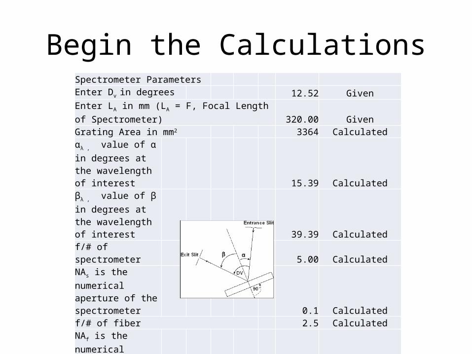
Begin the CalculationsSpectrometer Parameters Enter Dv in degrees 12.52 GivenEnter LA in mm (LA = F, Focal Length of Spectrometer) 320.00 GivenGrating Area in mm2 3364 Calculated
αλ , value of α in degrees at the wavelength of interest 15.39 Calculated
βλ , value of β in degrees at the wavelength of interest 39.39 Calculated
f/# of spectrometer 5.00 Calculated
NAs is the numerical aperture of the spectrometer 0.1 Calculatedf/# of fiber 2.5 Calculated
NAf is the numerical aperture of the fiber 0.22 Given

Complete Optical Path Optimization for a Czerny- Turner Spectrograph that Employs a Fiber Optic Cable to Supply Light to the Entrance Slit
• Step 1. Calculate the entendue of the light source, G
where S = area of light source, mm2 and r = radius of fiber, mm
where G = geometric entendue, S = area of light source, NAf = numerical
aperture of the fiber
S = 7.85E-01 mm
G = 1.19E-01 mm2
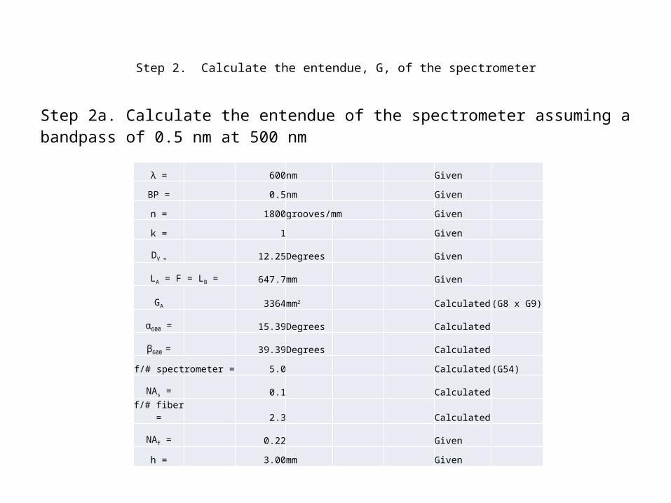
Step 2. Calculate the entendue, G, of the spectrometer
Step 2a. Calculate the entendue of the spectrometer assuming a bandpass of 0.5 nm at 500 nm
λ = 600nm Given
BP = 0.5nm Given
n = 1800grooves/mm Given
k = 1 Given
DV = 12.25Degrees Given
LA = F = LB = 647.7mm Given
GA 3364mm2 Calculated (G8 x G9)
α600 = 15.39Degrees Calculated
β600 = 39.39Degrees Calculated
f/# spectrometer = 5.0 Calculated (G54)
NAs = 0.1 Calculated
f/# fiber = 2.3 Calculated
NAf = 0.22 Given
h = 3.00mm Given

Calculate entrance slit width and area
= 0.5829mm
= 1.74879mm2
Calculate exit slit width
0.5829mm
Finally, calculate G of the spectrometer
1.40E-02 spectrometer
1.19E-01 fiber
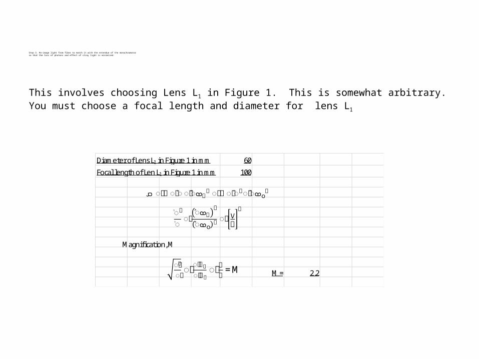
Step 3. Re-image light from fiber to match it with the entendue of the monochromatorso that the loss of photons and effect of stray light is minimized.
This involves choosing Lens L1 in Figure 1. This is somewhat arbitrary.You must choose a focal length and diameter for lens L1
Diameter of Lens L1 in Figure 1 in mm 60
Focal length of Len L1 in Figure 1 in mm 100
M = 2.2
ܩ ൌߨ��ൈ��ൈ��ܣ ଶ ൌߨ��ൈ��ᇱൈ��ܣ௦ଶ
�ᇱ
�ൌ��
ܣ� ଶ
௦ܣ� ଶ ൌ��ݍ ଶ
Magnification, M
ௌ��ᇲ
ௌ��ൌ��
ே� ே�ೞ
ൌ�� = M

Solve for p and q p = 145mm(q = M x p) q = 320mm
Solve for d, diameter of lens L1 d = 64mm
Solve for d, diameter of Lens L1 d = 64mm
1𝐹
=1𝑝
+1𝑞

𝐹¿ (𝑠𝑝𝑒𝑐𝑡𝑟𝑜𝑚𝑒𝑡𝑒𝑟 )= 1
2×𝑁𝐴𝑠
=𝑞𝑑
Solve for d, diameter of lens L1 d = 64mm
Solve for d, diameter of Lens L1 d = 64mm
𝐹¿ (𝐹𝑖𝑏𝑒𝑟 )= 1
2×𝑁𝐴 𝑓
=𝑝𝑑
Therefore, all the light from the fiber is collected by a lens, L1, with an object distance of p mm and will project an image of the fiber core on the spectrometer entrance slit q mm from lens, L1


Acknowledgement
Thank you!Arkansas Space Grant ConsortiumMontana Space Grant Consortium