designing a communication system for ivas - stereo …829640/fulltext01.pdf · mee10:29 designing a...
TRANSCRIPT
MEE10:29
Designing a communication
system for IVAS -
Stereo Video Coding Based
on H.264
Qiao Cheng
Wang Cang
This thesis is presented as part of Degree of
Master of Science in Electrical Engineering
Blekinge Institute of Technology
May 2010
Blekinge Institute of Technology
School of Engineering
Department of Telcommunication
Supervisor: Dr. Siamak Khatib
Examiner: Dr. Siamak Khatib

1
Abstract With the rapid development of 3D and communication technology, there are many
potential application areas of stereoscopic video such as education, manufacturing,
inspection and monitoring, entertainment, medical surgery, videoconferencing, and
video telephony etc.
In this thesis, we worked on the schemes of stereo video coding designing and
comparison to find out the best performance design. Video coding is an essential
procedure to reduce the data size and improve transmission efficiency. Stereo video
usually needs two and more cameras to capture videos. As we know video files
include huge information and massive correlations among frames, furthermore stereo
video coding requires considering spatial and temporal redundancies at the meantime.
Different video standards developed and applied in different fields, H.264 is a latest
standard developed by ITU-T Video Coding Experts Group (VCEG) together with the
ISO/IEC Moving Picture Experts Group (MPEG), as we selected compression
standard it have many advanced specifics for stereo video coding. For this reason all
schemes in this paper we designed are based on H.264 standard.
In this thesis, we designed a set of scenarios with four schemes. Each scheme is
probably the best one in different test environments. Accordingly we configure the
same parameters in software environment both JM (Joint Model) and JMVC (Joint
Multi-view Video Coding). The tested sequences are captured from different scene
and resolution to make sure that our analysis and conclusions are fair. With all the
results we got from all the scenarios, one out of the four schemes turned out to be the
best choice in most cases in this thesis.
Keywords: Stereo video coding, Disparity estimation, Motion estimation, H.264,
PSNR

2
3
Table of Content
Abstract 1
Acknowledgement 4
1. Introduction 5
1.1 Motivation and IVAS 5
1.2 Background 6
1.3 Research Aim and Objects 6
1.4 Outline of the Thesis 7
2. Stereo Vision Basics 8
2.1 Human Visual System and Depth Cue 8
2.2 Epipolar geometry and Camera Setup 8
2.3 Stereo Capture and Display Techniques 10
2.4 Color space introductions 12
3. Disparity and Occlusion 15
3.1Binocular Disparity 15
3.2Disparity Estimation 16
3.3 Occlusion Effect 18
4. Video Compression and Stereo Video Coding 21
4.1 Video Compression 21
4.2 Motion Estimation and H264 22
4.3 Video coding standards 25
4.4 Binocular correlation and stereoscopic video coding 26
4.4.1 Binocular correlation 26
4.4.2 Stereo video coding 27
5. Design and Implementation 28
5.1 Design and Schemes 28
5.2 Test environment and material 29
5.3 Implementation 31
5.4 Result and analysis 34
6. Conclusion and Future research 38
6.1 Conclusion 38
6.2 Future research 38
7. Reference 39

4
Acknowledgement
This paper is under the guidance of Dr. Siamak Khatibi completed. His profound
professional knowledge and strict attitude toward affect us. This paper from the
selection of subjects to complete each step is completed under the guidance of
supervisor who gives us much help. We would like to express our gratitude to him,
and thank Jiandan Chen, Benny and Wei Wen for their help on this thesis.
5
1. Introduction
1.1 Motivation and IVAS
With the rapid development of 3D and communication technology, there are many
potential application areas of stereoscopic video such as education, manufacturing,
inspection and monitoring, entertainment, medical surgery, videoconferencing, and
video telephony etc.
Human activities spaceIntelligent agent
Vision sensor system
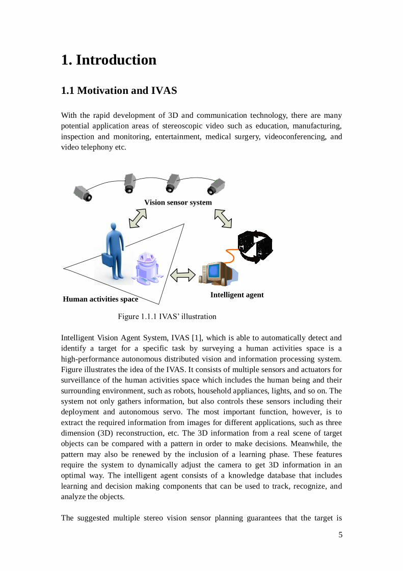
Figure 1.1.1 IVAS‟ illustration
Intelligent Vision Agent System, IVAS [1], which is able to automatically detect and
identify a target for a specific task by surveying a human activities space is a
high-performance autonomous distributed vision and information processing system.
Figure illustrates the idea of the IVAS. It consists of multiple sensors and actuators for
surveillance of the human activities space which includes the human being and their
surrounding environment, such as robots, household appliances, lights, and so on. The
system not only gathers information, but also controls these sensors including their
deployment and autonomous servo. The most important function, however, is to
extract the required information from images for different applications, such as three
dimension (3D) reconstruction, etc. The 3D information from a real scene of target
objects can be compared with a pattern in order to make decisions. Meanwhile, the
pattern may also be renewed by the inclusion of a learning phase. These features
require the system to dynamically adjust the camera to get 3D information in an
optimal way. The intelligent agent consists of a knowledge database that includes
learning and decision making components that can be used to track, recognize, and
analyze the objects.
The suggested multiple stereo vision sensor planning guarantees that the target is
6
observed under efficient visibility and the required depth reconstruction accuracy. The
constraints of the target space, the stereo pairs‟ properties, and the reconstruction
accuracy have been explored in the research conducted as a part of the project.
Similar to the human eyes, stereo vision observes the world from two different points
of view. At least two images need to be fused to obtain a depth perception of the
world to realize 3D world. However, due to the digital camera principle, the depth
reconstruction accuracy is limited by the sensor pixel resolution and causes
quantization of the reconstructed 3D space. Obviously 3D video have many
unparalleled advantages, but also need much bandwidth to store and transmit, so
compression is a essential part for the IVAS.
In this thesis we would like to investigate the stereo video transmission procedure to
compare different coding methods based on H.264 standard.
1.2 Background
Traditional display technique relays on mono lens camera. It only reflects a projection
of the world but without any depth information. If a true 3D world is going to be
shown, 3D image capture equipment must be adopted.
Video coding is a most important part for video compression. Since video stream
contains massive characterized information, video compression is almost necessary in
all engineering fields. Since video contains huge amount of visual information. Video
coding is almost a necessary procedure in every implementation applications. In the
past several decades, lots of efficiency video compression algorithms have been
developed and implemented in this area. Many high efficiency Video Coding
algorithms and standards have been made already.
The most popular standards are made by Mpeg (Moving Picture Experts Group) and
VCEG (Video Coding Experts Group).
But these algorithms and standards are designed for normal videos. Since in stereo
video or even multi-view case, information between channels are very similar. So
compression becomes essential when stereo recoded videos are transmitting or storing,
because in this case not only time redundancy but also spatial redundancy need to be
exploited.
1.3 Research Aim and Objects
In this thesis we are going to find and investigate some proper stereo video
compression methods that will fulfill the IVAS requirements.
7
The goal of this thesis is to test different stereo video coding methods based on H.264
standard. Then make quality comparison with method introduced with respect to
content based quality, size and coding complexity.
1.4 Outline of the Thesis
Chapter 2 has presented a brief introduction to the concepts of stereo vision basics. It
has discussed the binocular vision of human's visual system, epipolar geometry, color
space basics and gave a brief view of the stereo capture and display techniques.
Chapter 3 has presented basic binocular disparity concepts, disparity estimation
algorithms and rectification methods. Occlusion effect and the reconstructed
performance improving solutions such as texture synthesis are introduced.
Chapter 4 has presented a brief introduction to the concepts of video compression.
Then, the latest video coding standard H.264 is introduced. And in this chapter, stereo
video coding which is the key part to the entire thesis is studied.
Chapter 5 is the experimental part of the thesis. This chapter provides details of stereo
video coding schemes and implementation methods. The test results are analyzed and
concluded.
Chapter 6 evaluates the entire thesis and gives some advice for future research.
8
2. Stereo Vision Basics
2.1 Human Visual System and Depth Cue
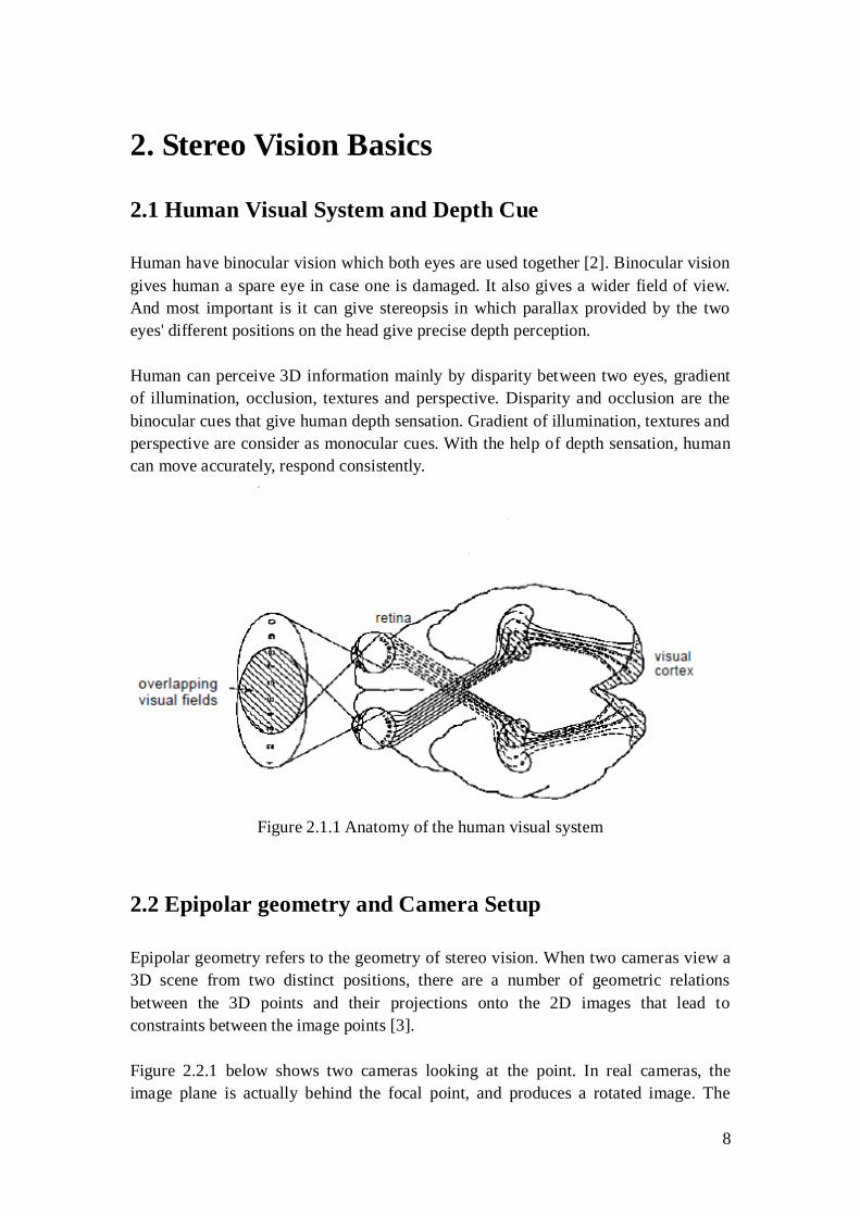
Human have binocular vision which both eyes are used together [2]. Binocular vision
gives human a spare eye in case one is damaged. It also gives a wider field of view.
And most important is it can give stereopsis in which parallax provided by the two
eyes' different positions on the head give precise depth perception.
Human can perceive 3D information mainly by disparity between two eyes, gradient
of illumination, occlusion, textures and perspective. Disparity and occlusion are the
binocular cues that give human depth sensation. Gradient of illumination, textures and
perspective are consider as monocular cues. With the help of depth sensation, human
can move accurately, respond consistently.
Figure 2.1.1 Anatomy of the human visual system
2.2 Epipolar geometry and Camera Setup
Epipolar geometry refers to the geometry of stereo vision. When two cameras view a
3D scene from two distinct positions, there are a number of geometric relations
between the 3D points and their projections onto the 2D images that lead to
constraints between the image points [3].
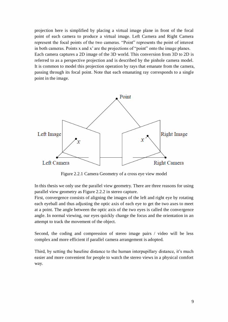
Figure 2.2.1 below shows two cameras looking at the point. In real cameras, the
image plane is actually behind the focal point, and produces a rotated image. The
9
projection here is simplified by placing a virtual image plane in front of the focal
point of each camera to produce a virtual image. Left Camera and Right Camera
represent the focal points of the two cameras. “Point” represents the point of interest
in both cameras. Points x and x‟ are the projections of “point” onto the image planes.
Each camera captures a 2D image of the 3D world. This conversion from 3D to 2D is
referred to as a perspective projection and is described by the pinhole camera model.
It is common to model this projection operation by rays that emanate from the camera,
passing through its focal point. Note that each emanating ray corresponds to a single
point in the image.
Figure 2.2.1 Camera Geometry of a cross eye view model
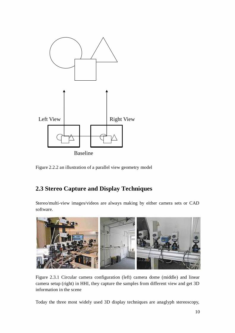
In this thesis we only use the parallel view geometry. There are three reasons for using
parallel view geometry as Figure 2.2.2 in stereo capture.
First, convergence consists of aligning the images of the left and right eye by rotating
each eyeball and thus adjusting the optic axis of each eye to get the two axes to meet
at a point. The angle between the optic axis of the two eyes is called the convergence
angle. In normal viewing, our eyes quickly change the focus and the orientation in an
attempt to track the movement of the object.
Second, the coding and compression of stereo image pairs / video will be less
complex and more efficient if parallel camera arrangement is adopted.
Third, by setting the baseline distance to the human interpupillary distance, it‟s much
easier and more convenient for people to watch the stereo views in a physical comfort
way.
10
Left View Right View
Baseline
Figure 2.2.2 an illustration of a parallel view geometry model
2.3 Stereo Capture and Display Techniques
Stereo/multi-view images/videos are always making by either camera sets or CAD
software.
Figure 2.3.1 Circular camera configuration (left) camera dome (middle) and linear
camera setup (right) in HHI, they capture the samples from different view and get 3D
information in the scene
Today the three most widely used 3D display techniques are anaglyph stereoscopy,
11
polarized display system and Liquid crystal shutter glasses.
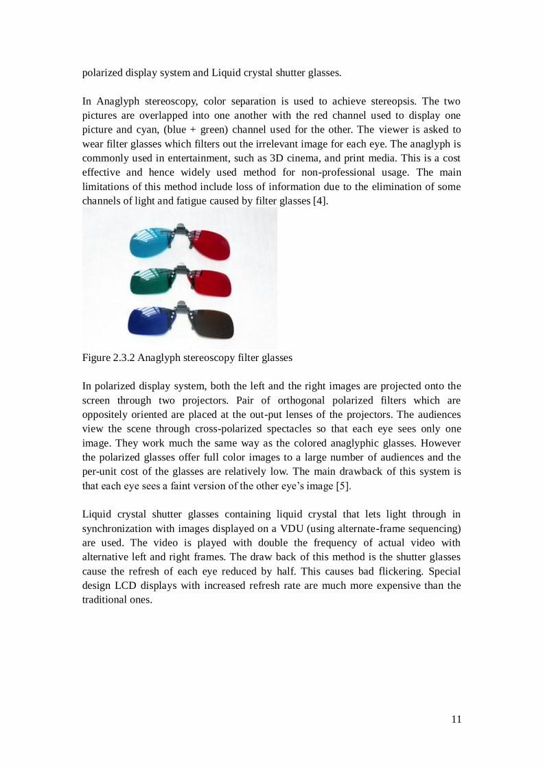
In Anaglyph stereoscopy, color separation is used to achieve stereopsis. The two
pictures are overlapped into one another with the red channel used to display one
picture and cyan, (blue + green) channel used for the other. The viewer is asked to
wear filter glasses which filters out the irrelevant image for each eye. The anaglyph is
commonly used in entertainment, such as 3D cinema, and print media. This is a cost
effective and hence widely used method for non-professional usage. The main
limitations of this method include loss of information due to the elimination of some
channels of light and fatigue caused by filter glasses [4].
Figure 2.3.2 Anaglyph stereoscopy filter glasses
In polarized display system, both the left and the right images are projected onto the
screen through two projectors. Pair of orthogonal polarized filters which are
oppositely oriented are placed at the out-put lenses of the projectors. The audiences
view the scene through cross-polarized spectacles so that each eye sees only one
image. They work much the same way as the colored anaglyphic glasses. However
the polarized glasses offer full color images to a large number of audiences and the
per-unit cost of the glasses are relatively low. The main drawback of this system is
that each eye sees a faint version of the other eye‟s image [5].
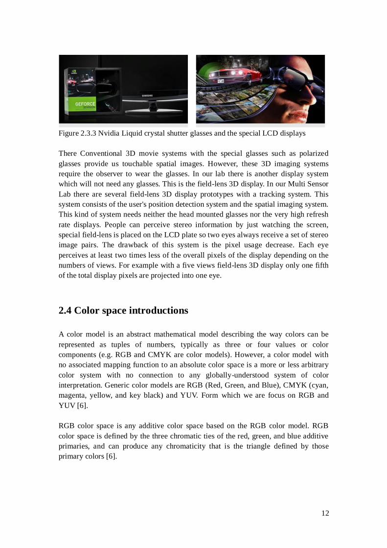
Liquid crystal shutter glasses containing liquid crystal that lets light through in
synchronization with images displayed on a VDU (using alternate-frame sequencing)
are used. The video is played with double the frequency of actual video with
alternative left and right frames. The draw back of this method is the shutter glasses
cause the refresh of each eye reduced by half. This causes bad flickering. Special
design LCD displays with increased refresh rate are much more expensive than the
traditional ones.
12
Figure 2.3.3 Nvidia Liquid crystal shutter glasses and the special LCD displays
There Conventional 3D movie systems with the special glasses such as polarized
glasses provide us touchable spatial images. However, these 3D imaging systems
require the observer to wear the glasses. In our lab there is another display system
which will not need any glasses. This is the field-lens 3D display. In our Multi Sensor
Lab there are several field-lens 3D display prototypes with a tracking system. This
system consists of the user's position detection system and the spatial imaging system.
This kind of system needs neither the head mounted glasses nor the very high refresh
rate displays. People can perceive stereo information by just watching the screen,
special field-lens is placed on the LCD plate so two eyes always receive a set of stereo
image pairs. The drawback of this system is the pixel usage decrease. Each eye
perceives at least two times less of the overall pixels of the display depending on the
numbers of views. For example with a five views field-lens 3D display only one fifth
of the total display pixels are projected into one eye.
2.4 Color space introductions
A color model is an abstract mathematical model describing the way colors can be
represented as tuples of numbers, typically as three or four values or color
components (e.g. RGB and CMYK are color models). However, a color model with
no associated mapping function to an absolute color space is a more or less arbitrary
color system with no connection to any globally-understood system of color
interpretation. Generic color models are RGB (Red, Green, and Blue), CMYK (cyan,
magenta, yellow, and key black) and YUV. Form which we are focus on RGB and
YUV [6].
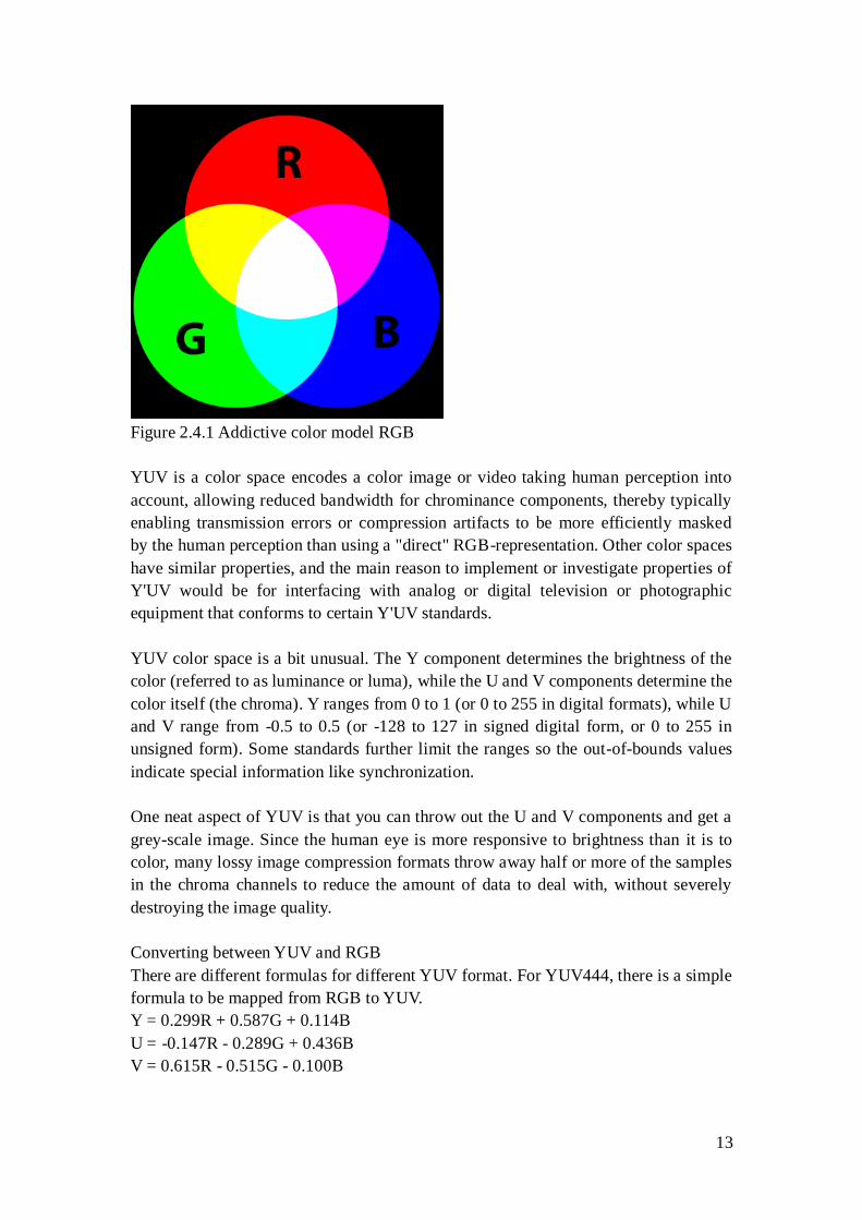
RGB color space is any additive color space based on the RGB color model. RGB
color space is defined by the three chromatic ties of the red, green, and blue additive
primaries, and can produce any chromaticity that is the triangle defined by those
primary colors [6].
13
Figure 2.4.1 Addictive color model RGB
YUV is a color space encodes a color image or video taking human perception into
account, allowing reduced bandwidth for chrominance components, thereby typically
enabling transmission errors or compression artifacts to be more efficiently masked
by the human perception than using a "direct" RGB-representation. Other color spaces
have similar properties, and the main reason to implement or investigate properties of
Y'UV would be for interfacing with analog or digital television or photographic
equipment that conforms to certain Y'UV standards.
YUV color space is a bit unusual. The Y component determines the brightness of the
color (referred to as luminance or luma), while the U and V components determine the
color itself (the chroma). Y ranges from 0 to 1 (or 0 to 255 in digital formats), while U
and V range from -0.5 to 0.5 (or -128 to 127 in signed digital form, or 0 to 255 in
unsigned form). Some standards further limit the ranges so the out-of-bounds values
indicate special information like synchronization.
One neat aspect of YUV is that you can throw out the U and V components and get a
grey-scale image. Since the human eye is more responsive to brightness than it is to
color, many lossy image compression formats throw away half or more of the samples
in the chroma channels to reduce the amount of data to deal with, without severely
destroying the image quality.
Converting between YUV and RGB
There are different formulas for different YUV format. For YUV444, there is a simple
formula to be mapped from RGB to YUV.
Y = 0.299R + 0.587G + 0.114B
U = -0.147R - 0.289G + 0.436B
V = 0.615R - 0.515G - 0.100B
14
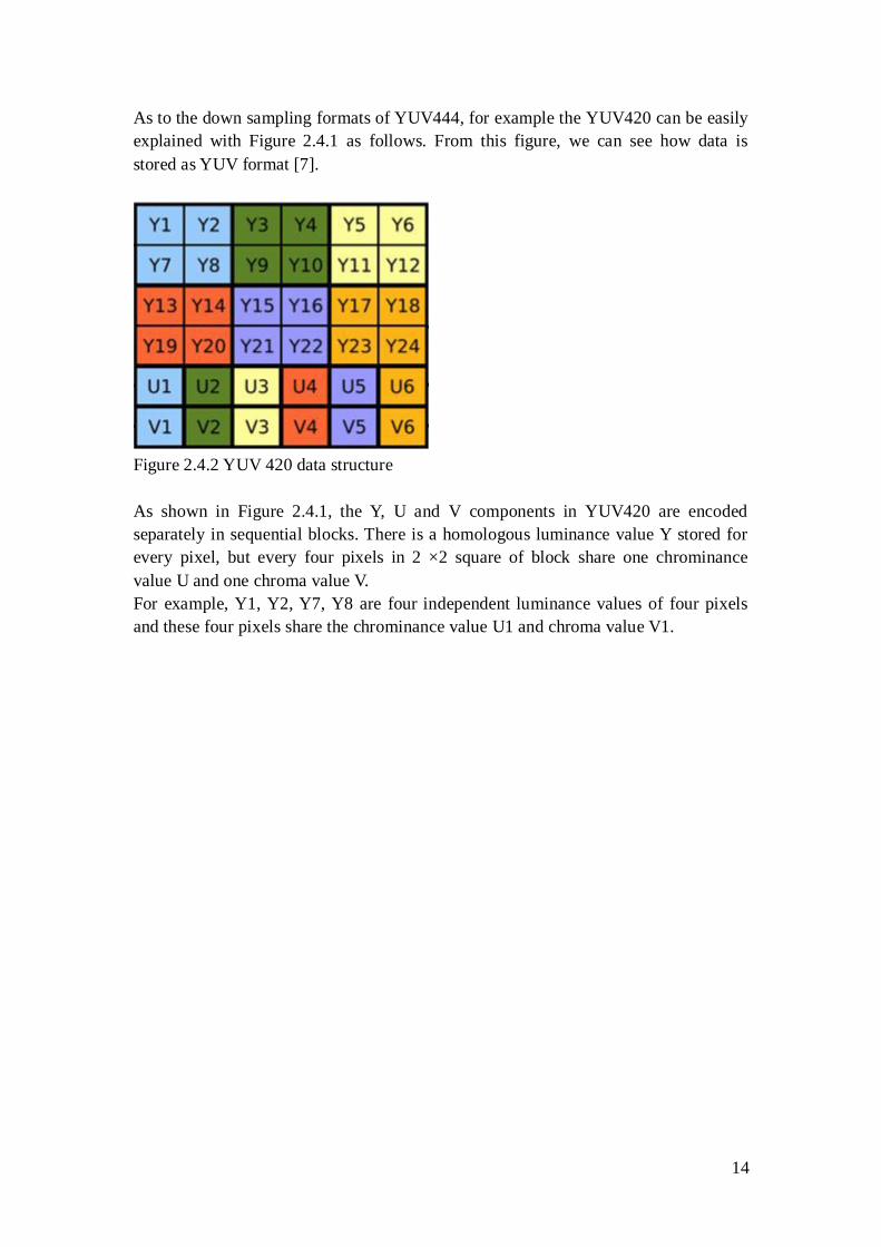
As to the down sampling formats of YUV444, for example the YUV420 can be easily
explained with Figure 2.4.1 as follows. From this figure, we can see how data is
stored as YUV format [7].
Figure 2.4.2 YUV 420 data structure
As shown in Figure 2.4.1, the Y, U and V components in YUV420 are encoded
separately in sequential blocks. There is a homologous luminance value Y stored for
every pixel, but every four pixels in 2 ×2 square of block share one chrominance
value U and one chroma value V.
For example, Y1, Y2, Y7, Y8 are four independent luminance values of four pixels
and these four pixels share the chrominance value U1 and chroma value V1.
15
3. Disparity and Occlusion
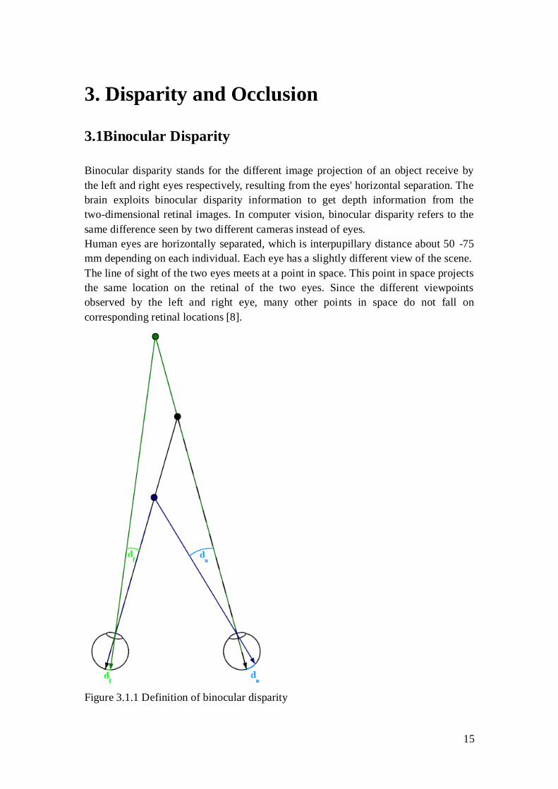
3.1Binocular Disparity
Binocular disparity stands for the different image projection of an object receive by
the left and right eyes respectively, resulting from the eyes' horizontal separation. The
brain exploits binocular disparity information to get depth information from the
two-dimensional retinal images. In computer vision, binocular disparity refers to the
same difference seen by two different cameras instead of eyes.
Human eyes are horizontally separated, which is interpupillary distance about 50 -75
mm depending on each individual. Each eye has a slightly different view of the scene.
The line of sight of the two eyes meets at a point in space. This point in space projects
the same location on the retinal of the two eyes. Since the different viewpoints
observed by the left and right eye, many other points in space do not fall on
corresponding retinal locations [8].
Figure 3.1.1 Definition of binocular disparity
16
In Figure 3.1.1: The nearest point is the point of fixation. The middle point lies nearer
to the observer. Therefore it has a "near" disparity dn. Point lying more far away
correspondingly have a "far" disparity df. Binocular disparity is the angle between
two lines of projection in one eye. One of which is the real projection from the object
to the actual point of projection. The other one is the imaginary projection going
through the focal point of the lens of the one eye to the point corresponding to the
actual point of projection in the other eye. For simplicity reasons here both objects lay
on the line of fixation for one eye such that the imaginary projection ends directly on
the fovea of the other eye, but in general the fovea acts at most as a reference. Note
that far disparities are smaller than near disparities for objects having the same
distance from the fixation point.
In computer stereo vision, there is no interpupillary distance. Instead, there is a
variables distance between the two cameras. This distance is called the baseline.
Disparity increases as the baseline increases, due to the view of the cameras becoming
more and more different.
3.2Disparity Estimation
In this thesis we adopt the regional pixel based algorithm. We will give a brief view of
this algorithm.
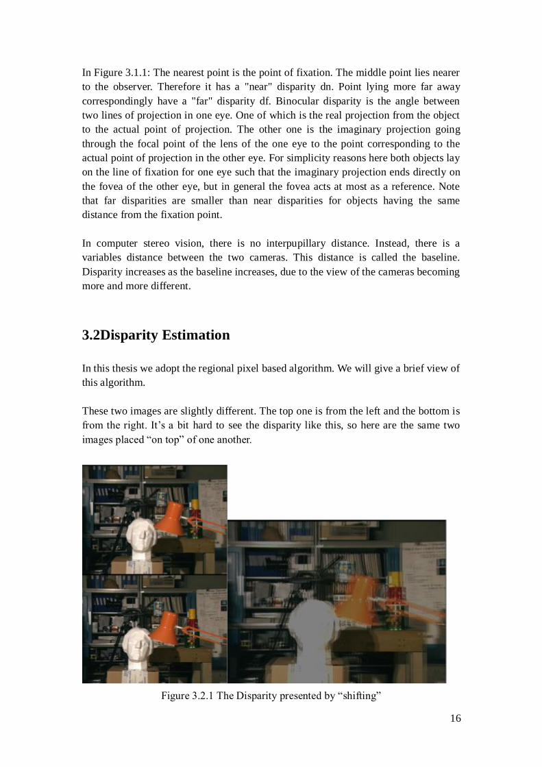
These two images are slightly different. The top one is from the left and the bottom is
from the right. It‟s a bit hard to see the disparity like this, so here are the same two
images placed “on top” of one another.
Figure 3.2.1 The Disparity presented by “shifting”
17
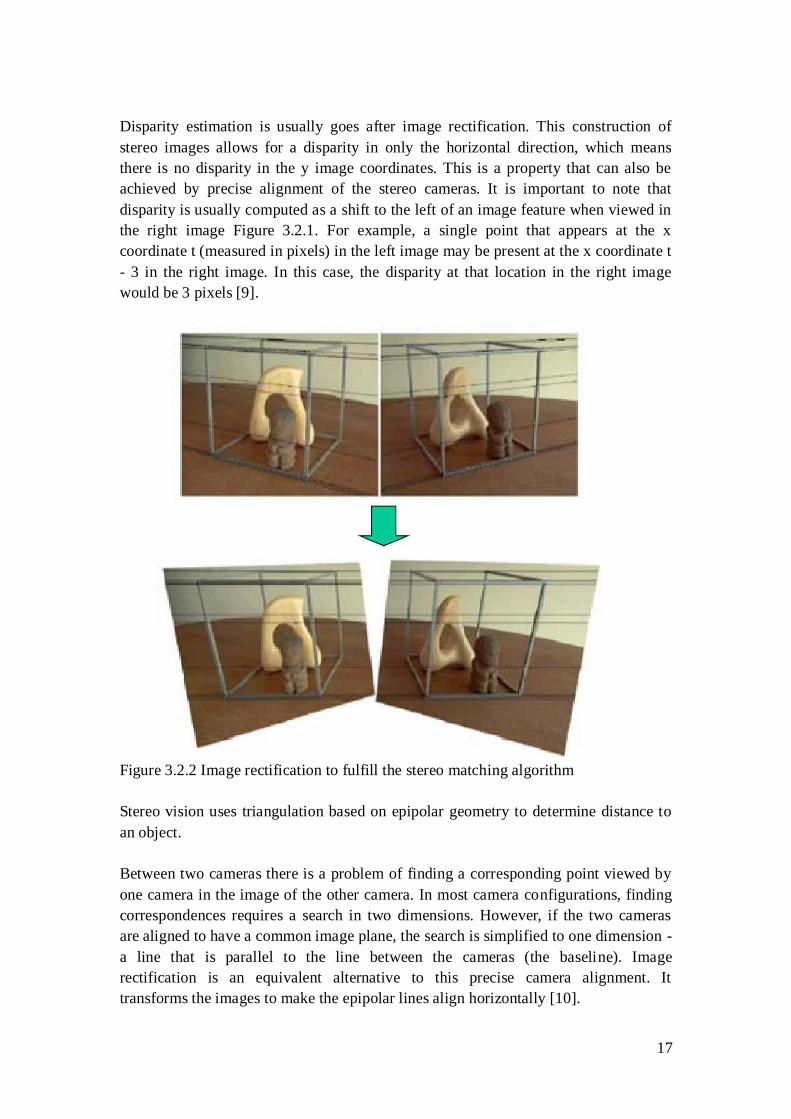
Disparity estimation is usually goes after image rectification. This construction of
stereo images allows for a disparity in only the horizontal direction, which means
there is no disparity in the y image coordinates. This is a property that can also be
achieved by precise alignment of the stereo cameras. It is important to note that
disparity is usually computed as a shift to the left of an image feature when viewed in
the right image Figure 3.2.1. For example, a single point that appears at the x
coordinate t (measured in pixels) in the left image may be present at the x coordinate t
- 3 in the right image. In this case, the disparity at that location in the right image
would be 3 pixels [9].
Figure 3.2.2 Image rectification to fulfill the stereo matching algorithm
Stereo vision uses triangulation based on epipolar geometry to determine distance to
an object.
Between two cameras there is a problem of finding a corresponding point viewed by
one camera in the image of the other camera. In most camera configurations, finding
correspondences requires a search in two dimensions. However, if the two cameras
are aligned to have a common image plane, the search is simplified to one dimension -
a line that is parallel to the line between the cameras (the baseline). Image
rectification is an equivalent alternative to this precise camera alignment. It
transforms the images to make the epipolar lines align horizontally [10].
18
After rectification, a simple computational measure such as the Sum of absolute
differences can be used to compute disparities at each pixel in the right image. This is
achieved by taking a "patch" (often square) of pixels in the left image. Then find the
corresponding patch at each valid disparity in the right image. For example, for a
disparity of 0, the two patches would be at the exact same location in both images. So,
for a disparity of 1, the patch in the right image for a disparity of 0 would simply be
moved 1 pixel to the left.
The absolute difference is then computed for corresponding pixels in each patch.
These absolute differences are then summed to compute the final SAD score. After
this SAD score has been computed for all valid disparities, the disparity that produces
the lowest SAD score is determined to be the disparity at that location in the right
image.
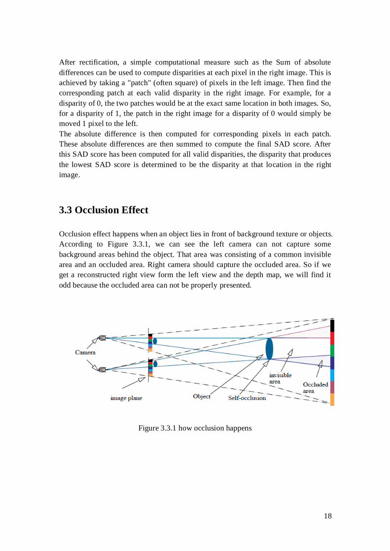
3.3 Occlusion Effect
Occlusion effect happens when an object lies in front of background texture or objects.
According to Figure 3.3.1, we can see the left camera can not capture some
background areas behind the object. That area was consisting of a common invisible
area and an occluded area. Right camera should capture the occluded area. So if we
get a reconstructed right view form the left view and the depth map, we will find it
odd because the occluded area can not be properly presented.
Figure 3.3.1 how occlusion happens
19
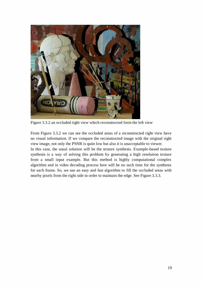
Figure 3.3.2 an occluded right view which reconstructed form the left view
From Figure 3.3.2 we can see the occluded areas of a reconstructed right view have
no visual information. If we compare the reconstructed image with the original right
view image, not only the PSNR is quite low but also it is unacceptable to viewer.
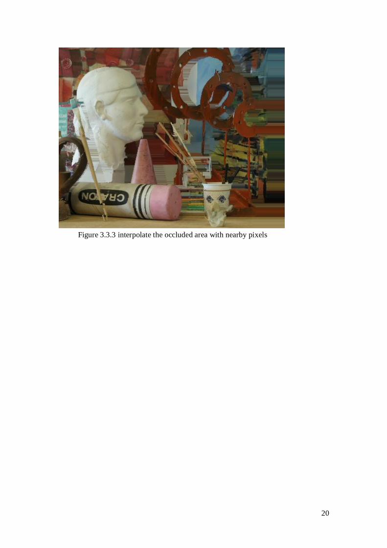
In this case, the usual solution will be the texture synthesis. Example-based texture
synthesis is a way of solving this problem by generating a high resolution texture
from a small input example. But this method is highly computational complex
algorithm and in video decoding process here will be no such time for the synthesis
for each frame. So, we use an easy and fast algorithm to fill the occluded areas with
nearby pixels from the right side in order to maintain the edge. See Figure 3.3.3.
20
Figure 3.3.3 interpolate the occluded area with nearby pixels
21
4. Video Compression and Stereo Video
Coding
4.1 Video Compression
Video compression refers to reducing the quantity of data used to represent digital
video images, and is a combination of spatial image compression and temporal
motion compensation.[11] Video compression is an example of the concept of source
coding in Information theory.
Video image data have a strong correlation that is meaning there is a large number of
redundant information, which can be divided into the redundant information in space domain
and the redundant information in time domain. Compression technology is to remove
redundant information in the data which means to remove the correlation between the data;
compression technique includes the intra-frame image data compression techniques, the
inter-frame image data compression techniques and entropy coding compression technology.
Remove redundant information in time domain
The use of inter-frame coding techniques can remove redundant informati
on in time domain, which includes the following three parts:
-Motion Compensation
Motion compensation is to predict and compensate the current partial
images through the previous local images, which is an effective way of reducing
redundant information in the frame.
-Movement expresses
Different regions of the image need to use different motion vectors to
describe the motion information. Motion vector is compressed by entropy
coding.
-Motion Estimation
Motion estimation is a set of technology that it extracts motion information
from the video sequences.
Remove redundant information in space domain
Mainly in intra-frame coding techniques and entropy coding technique
- Transform coding
22
Intra-image and prediction differential signal has a very high redundancy of
time-space domain. Transformation coding is that the special signal will be
transformed into another orthogonal vector space, so that their correlation
decreases and the data redundancy reduce.
- Quantization coding
After transform coding, it will get a number of transform coefficients and
quantifies these coefficients, so that the output of the encoder could achie ve a
certain bit rate. This process led that accuracy reduces.
- Entropy coding
Entropy coding is a lossless encoding. It will further compress the coefficients
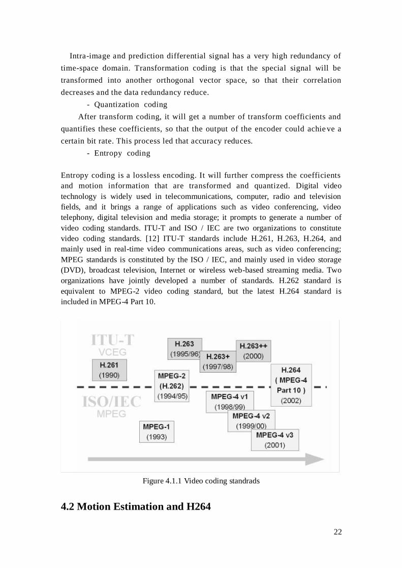
and motion information that are transformed and quantized. Digital video
technology is widely used in telecommunications, computer, radio and television
fields, and it brings a range of applications such as video conferencing, video
telephony, digital television and media storage; it prompts to generate a number of
video coding standards. ITU-T and ISO / IEC are two organizations to constitute
video coding standards. [12] ITU-T standards include H.261, H.263, H.264, and
mainly used in real-time video communications areas, such as video conferencing;
MPEG standards is constituted by the ISO / IEC, and mainly used in video storage
(DVD), broadcast television, Internet or wireless web-based streaming media. Two
organizations have jointly developed a number of standards. H.262 standard is
equivalent to MPEG-2 video coding standard, but the latest H.264 standard is
included in MPEG-4 Part 10.
Figure 4.1.1 Video coding standrads
4.2 Motion Estimation and H264
23
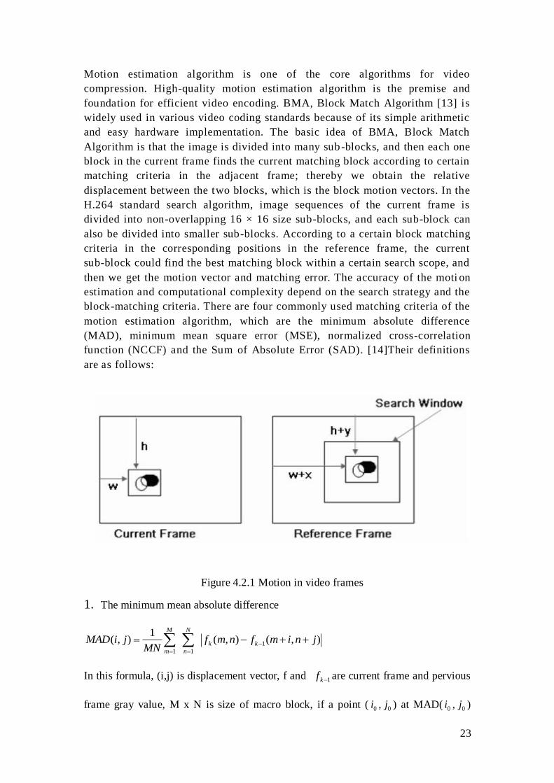
Motion estimation algorithm is one of the core algorithms for video
compression. High-quality motion estimation algorithm is the premise and
foundation for efficient video encoding. BMA, Block Match Algorithm [13] is
widely used in various video coding standards because of its simple arithmetic
and easy hardware implementation. The basic idea of BMA, Block Match
Algorithm is that the image is divided into many sub-blocks, and then each one
block in the current frame finds the current matching block according to certain
matching criteria in the adjacent frame; thereby we obtain the relative
displacement between the two blocks, which is the block motion vectors. In the
H.264 standard search algorithm, image sequences of the current frame is
divided into non-overlapping 16 × 16 size sub-blocks, and each sub-block can
also be divided into smaller sub-blocks. According to a certain block matching
criteria in the corresponding positions in the reference frame, the current
sub-block could find the best matching block within a certain search scope, and
then we get the motion vector and matching error. The accuracy of the moti on
estimation and computational complexity depend on the search strategy and the
block-matching criteria. There are four commonly used matching criteria of the
motion estimation algorithm, which are the minimum absolute difference
(MAD), minimum mean square error (MSE), normalized cross-correlation
function (NCCF) and the Sum of Absolute Error (SAD). [14]Their definitions
are as follows:
Figure 4.2.1 Motion in video frames
1. The minimum mean absolute difference
),(),(1
),( 1
11
jnimfnmfMN
jiMAD kk
N
n
M
m
In this formula, (i,j) is displacement vector, f and 1kf are current frame and pervious
frame gray value, M x N is size of macro block, if a point ( 0i , 0j ) at MAD( 0i , 0j )
24
reach the minimum, then the point is to find the best matching point.
2. Minimum Mean Squared Error
2
1
11
),(),(1
),(
jnimfnmfMN
jiMSE k
N
n
k
M
m
Minimum MSE value is the best matching point.
3. Normalized Cross Correlation Function
2/1
1 1
2
1
2/1
1 1
2
1
11
),(),(
),(),(
),(
M
m
N
n
k
M
m
N
n
k
k
N
n
k
M
m
jnimfnmf
jnimfnmf
jiNCCF
Maximum NCCF point of the optimal matching points
4. Sum of absolute error
M
m
kk
N
n
jnimfnmfjiSAD1
1
1
),(),(),(
In the motion estimation, the matching criteria for the accuracy of the matchin
g little effect, often instead of using the SAD operations. As the SAD criteria
need not be multiplication, so it is simple, convenient, and most frequently use
d. SAD (Sum of Absolute Difference) that the sum of absolute error, defined a
s follows:
In the H. 264 standards, the inter-frame predictive coding use the temporal
redundancy in continuous frames to carry out motion estimation and
compensation. Its motion compensation support for the previous video coding
standard in most of the key features, but also the flexibility to add more features,
in addition to support for P frames, B frames, H.264 also supports a new
inter-stream transmission frames -- -SP frame. Stream with SP frames, similar
in content but a different rate of fast switching between streams, while
supporting random access and fast playback modes. H.264 motion estimation
has the following four characteristics. [15]
(1) Different sizes and shapes of the macro block partition
For each 16 × 16-pixel macro block motion compensation can be used in
different sizes and shapes. H.264 supports seven kinds of mode. Small block
model of the motion compensation improve performance for processing
movement details, reducing blocking effects and improving image quality.
25
(2) High-precision sub-pixel motion compensation
H.263 is used in half pixel motion estimation, while in H.264 can be used in 1 /
4 or 1 / 8 pixel motion estimation. In the case of the same precision requirement,
residuals after H.264 using the 1 / 4 or 1 / 8 pixel precision motion estimation is
smaller than the H.263 using half pixel motion estimation. So that, under the
same accuracy, H.264 inter-frame coding in the required rate is even smaller.
(3) Multiple reference frames
H.264 offers optional multi-frame prediction, in the inter-frame encoding, five
different reference frames can be selected which provide a better error
correction performance and improve the video image quality. This feature is
mainly used in the following situations: a cyclical movement, translational
motion, in two different scenarios changes back and forth between the camera's
lenses.
(4) Deblocking filter
H.264 defines the adaptive filter to remove blocking effects, which can handle
the predicted loop in the horizontal and vertical block edges, greatly reducing
the blocking effects.
4.3 Video coding standards
The test platform for this project is the H.264/AVC standard, the H.264/AVC
reference software Joint Model (JM) [16] is used for coding single channel stream,
and Joint Multview Video Coding (JMVC) [17] is used for coding multview video.
H.264, also known as MPEG-4 Part 10 is for ITU-T Video Coding Experts Group
(VCEG) and ISO / IEC Moving Picture Experts Group (MPEG) formed a joint Joint
Video Team (JVT, Joint Video Team) made high compression digital video codec
standard.
The great advantage of H.264 is a very high data compression ratio, at the same
image quality conditions, H.264 compression ratio is 2 times higher than
MPEG-2, and 1.5 ~ 2 times higher than MPEG-4. [15]For example, the original
file size if it is 88GB, with MPEG-2 compression standard compressed into a
3.5GB, compression ratio of 25:1, while the use of H.264 compression standard
compressed into 879MB, from 88GB to 879MB, H.264 compression ratio to
achieve amazing 102:1! H.264 Why is there such a high compression ratio?
Low Bit Rate (Low Bit Rate) played an important role, and MPEG -2 and
MPEG-4 ASP compression technologies such as comparison, H.264
compression technology will greatly reduce the user's download time and data
traffic charges. Particularly worth mentioning is that, H.264 high compression
26
ratio at the same time also has high-quality flow images.
H.264 is based on MPEG-4 technology, encoding and decoding procedures
mainly includes five parts: the inter-frame and intra-prediction, transformation
and anti-transform, quantization and the inverse quantization, loop filter,
entropy coding.
It retains the advantages of the previous compression techniques and essence
but also has other compression technology cannot compare with many
advantages.
1.Low Bit Rate: compare with MPEG2 and MPEG4 ASP compression
techniques, in the same image quality, the use of H.264 technology, the amount
of data compressed is only the 1 / 8 MPEG2, M1 / 3 MPEG4.
Obviously, H.264 compression technology will significantly save the user's
download time and data traffic charges.
2.High quality image: H.264 can provide continuous, smooth, high-
quality images (DVD quality)
3.Fault-tolerant capability: H.264 provides necessary tool to solute packet
loss in unstable network environment
4.Network adaptability: H.264 provides network abstraction layer to make
the file of H.264 transmit in different network easily (internet, CDMA, GPRS,
WCDMA, and CDMA2000)
4.4 Binocular correlation and stereoscopic video coding
4.4.1 Binocular correlation
The binocular correlation is the most important, by itself, is sufficient for 3D
visualization. Most of the other cues are experience related. I.e., they are used by the
brain based on previously perceived depth and their effects. However the binocular
disparity can be based on a well defined algorithm not requiring a priori viewing of
the scene. A relevant example here would be the images from Mars Rovers (Spirit and
Opportunity), where humans do not have any a priori experience about the nature and
relative sizes of rocks. The following quote by a scientist working on this project
explains this:
27
“[There was] some misinterpretation when Opportunity first photographed the
intriguing rock outcropping at its landing site. At first, scientists thought it was 3 to 6
feet (1-2 meters) tall. Then with the help of 3-D data they were able to better
determine the distance from the rover to the ledge, and the feature's true height
became clear. Instead of a meter or two, it's 10 or 20 centimeters” [18]
In summary, a human being perceives a scene in 3D as follows: First, the scene in
3Dreal world is projected onto the retinas of the eyes as 2D images, where each eye
views a slightly different scene. Note that the 3D depth information is lost at this stage.
Then, the primary visual cortex in the brain fuses the stereo pair by stereopsis;
with/without the help of prior knowledge of the 3D world. Finally, by reconstructing
3D from 2D, a feeling of depth is perceived.
This means by providing two different 2D images from slightly different camera
positions to the two eyes, it should be possible to stimulate 3D perception.
4.4.2 Stereo video coding
The pursuit of quality and a sense of reality has always been the type of video-media
applications concern. The goal is to get as much as possible the human visual system,
the true visual experience, human vision is an important function is through the view
difference between left and right eyes to rise depth perception, the so-called
three-dimensional visual experience.
In order for the recipient to generate three-dimensional visual perception must be
carried out the two-way video that respective left and right eyes transmission on IP
network and at the receiving end reproduce and display, that is, transmission and
reconstruction of stereoscopic video.
Require three-dimensional framework for video transmission system has a universal,
compatible with a variety of video codes, the most basic way is to separate two-way
video is encoded independently, using one dimension video application system for
transmission, and at the receiving end of a specified the corresponding right and left
eyes, respectively, can also be a specific three-dimensional video encoding, and then
transmitted.
In order to effectively use of network bandwidth, the need for left and right eyes video
compression, can be applied to the current method of video compression, you can also
use the high correlation between right and left eyes to compress video of left eye and
disparity information.
28
5. Design and Implementation
5.1 Design and Schemes
This chapter provides details of stereo video coding schemes and implementation
methods. For this project, we investigated four stereo coding schemes in three groups
of sequences which captured in different scene and resolution. All schemes encoded
using H.264.
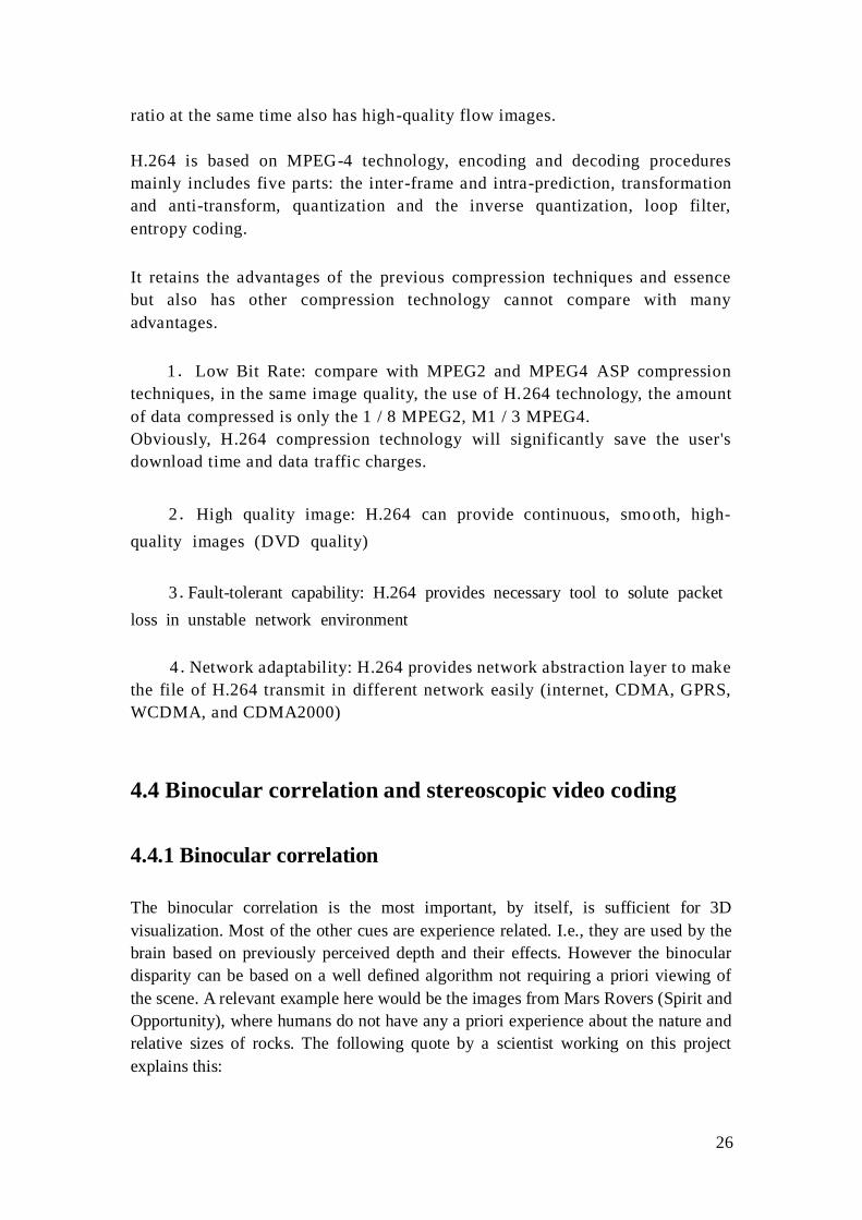
In scheme 1, [19] the left sequence and right sequence are encoded independently
with MCP (motion compensation prediction). The next figure depicts the prediction
mode. In this scheme, the temporal redundancy is used, but the relativity between the
left view and right view isn‟t exploited.
Figure 5.1.1 Scheme 1
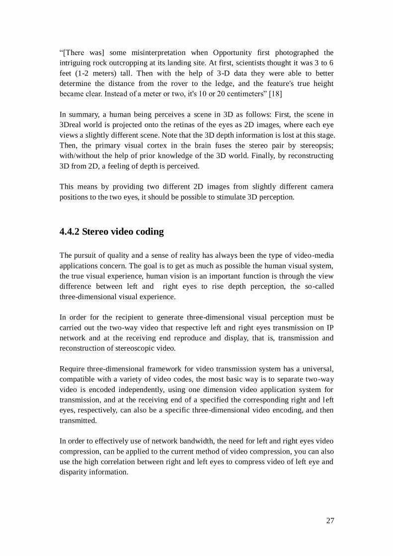
In scheme 2, the left sequence and right sequence are synthesized into one sequence,
and then incorporated sequence is coded with H.264. At the receiver part, it is
decoded and separated into left and right sequence.
Figure 5.1.2 Scheme 2
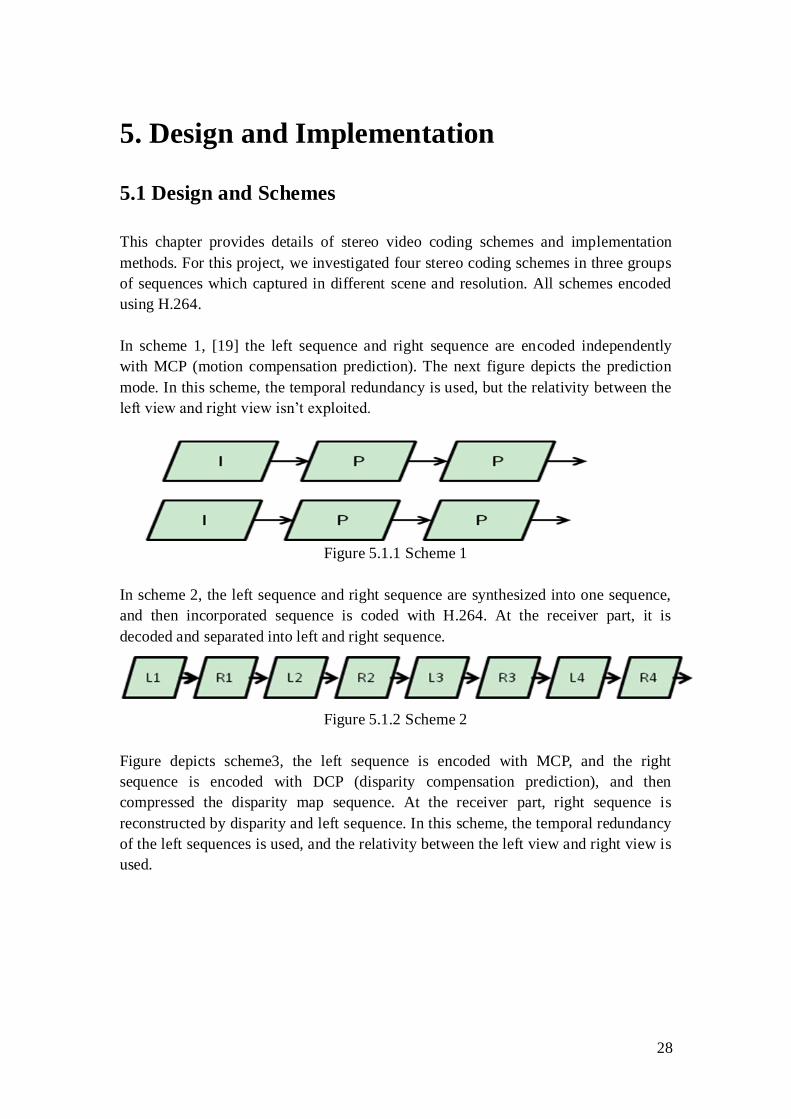
Figure depicts scheme3, the left sequence is encoded with MCP, and the right
sequence is encoded with DCP (disparity compensation prediction), and then
compressed the disparity map sequence. At the receiver part, right sequence is
reconstructed by disparity and left sequence. In this scheme, the temporal redundancy
of the left sequences is used, and the relativity between the left view and right view is
used.
29
Figure 5.1.3 Scheme 3
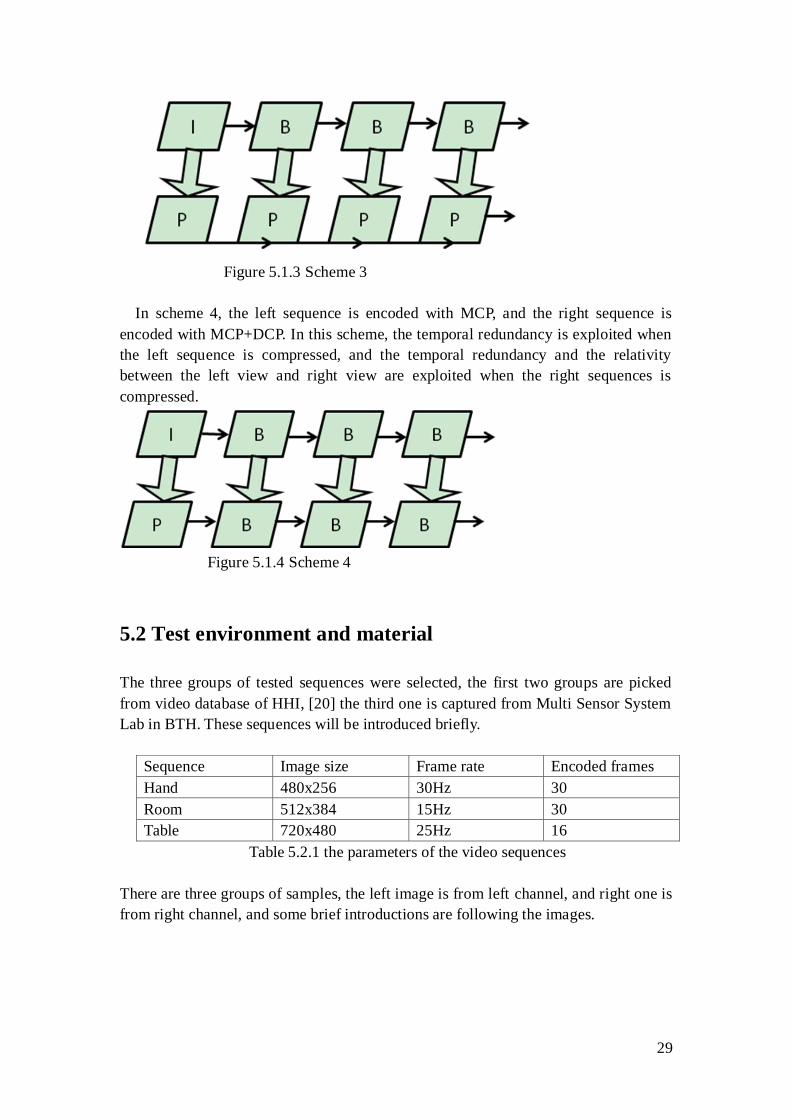
In scheme 4, the left sequence is encoded with MCP, and the right sequence is
encoded with MCP+DCP. In this scheme, the temporal redundancy is exploited when
the left sequence is compressed, and the temporal redundancy and the relativity
between the left view and right view are exploited when the right sequences is
compressed.
Figure 5.1.4 Scheme 4
5.2 Test environment and material
The three groups of tested sequences were selected, the first two groups are picked
from video database of HHI, [20] the third one is captured from Multi Sensor System
Lab in BTH. These sequences will be introduced briefly.
Sequence Image size Frame rate Encoded frames
Hand 480x256 30Hz 30
Room 512x384 15Hz 30
Table 720x480 25Hz 16
Table 5.2.1 the parameters of the video sequences
There are three groups of samples, the left image is from left channel, and right one is
from right channel, and some brief introductions are following the images.
30
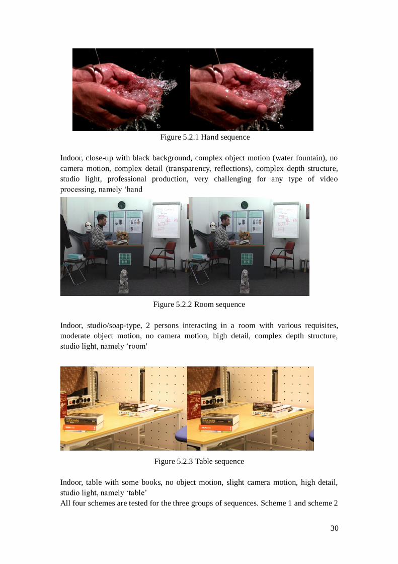
Figure 5.2.1 Hand sequence
Indoor, close-up with black background, complex object motion (water fountain), no
camera motion, complex detail (transparency, reflections), complex depth structure,
studio light, professional production, very challenging for any type of video
processing, namely „hand
Figure 5.2.2 Room sequence
Indoor, studio/soap-type, 2 persons interacting in a room with various requisites,
moderate object motion, no camera motion, high detail, complex depth structure,
studio light, namely „room'
Figure 5.2.3 Table sequence
Indoor, table with some books, no object motion, slight camera motion, high detail,
studio light, namely „table‟
All four schemes are tested for the three groups of sequences. Scheme 1 and scheme 2
31
are implemented with the model JM 16.1 [16], and the other two schemes are
implemented with the model JMVC 6.0 [17]. The JM and JMVC are configured in
same parameters.
QP (quality parameter) GOP (group of pictures) Ref frames Search range
35 8 1 16
Table 5.2.2 the key parameters in the coding configuration
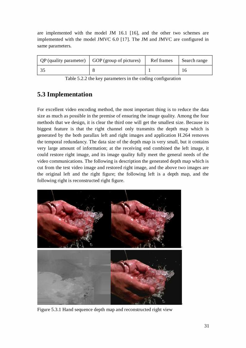
5.3 Implementation
For excellent video encoding method, the most important thing is to reduce the data
size as much as possible in the premise of ensuring the image quality. Among the four
methods that we design, it is clear the third one will get the smallest size. Because its
biggest feature is that the right channel only transmits the depth map which is
generated by the both parallax left and right images and application H.264 removes
the temporal redundancy. The data size of the depth map is very small, but it contains
very large amount of information; at the receiving end combined the left image, it
could restore right image, and its image quality fully meet the general needs of the
video communications. The following is description the generated depth map which is
cut from the test video image and restored right image, and the above two images are
the original left and the right figure; the following left is a depth map, and the
following right is reconstructed right figure.
Figure 5.3.1 Hand sequence depth map and reconstructed right view
32
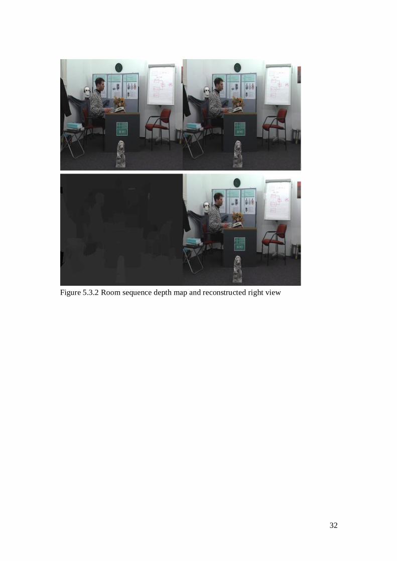
Figure 5.3.2 Room sequence depth map and reconstructed right view
33
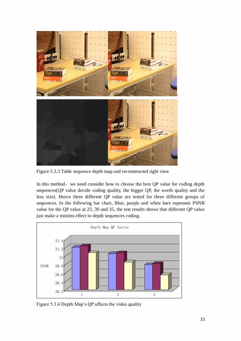
Figure 5.3.3 Table sequence depth map and reconstructed right view
In this method,we need consider how to choose the best QP value for coding depth
sequences(QP value decide coding quality, the bigger QP, the worth quality and the
less size). Hence three different QP value are tested for three different groups of
sequences. In the following bar chart, Blue, purple and white bars represent PSNR
value for the QP value at 25, 30 and 35, the test results shows that different QP value
just make a minims effect to depth sequences coding.
Figure 5.3.4 Depth Map‟s QP affects the video quality
30.2
30.4
30.6
30.8
31
31.2
31.4
PSNR
1 2 3
Depth Map QP factor
34
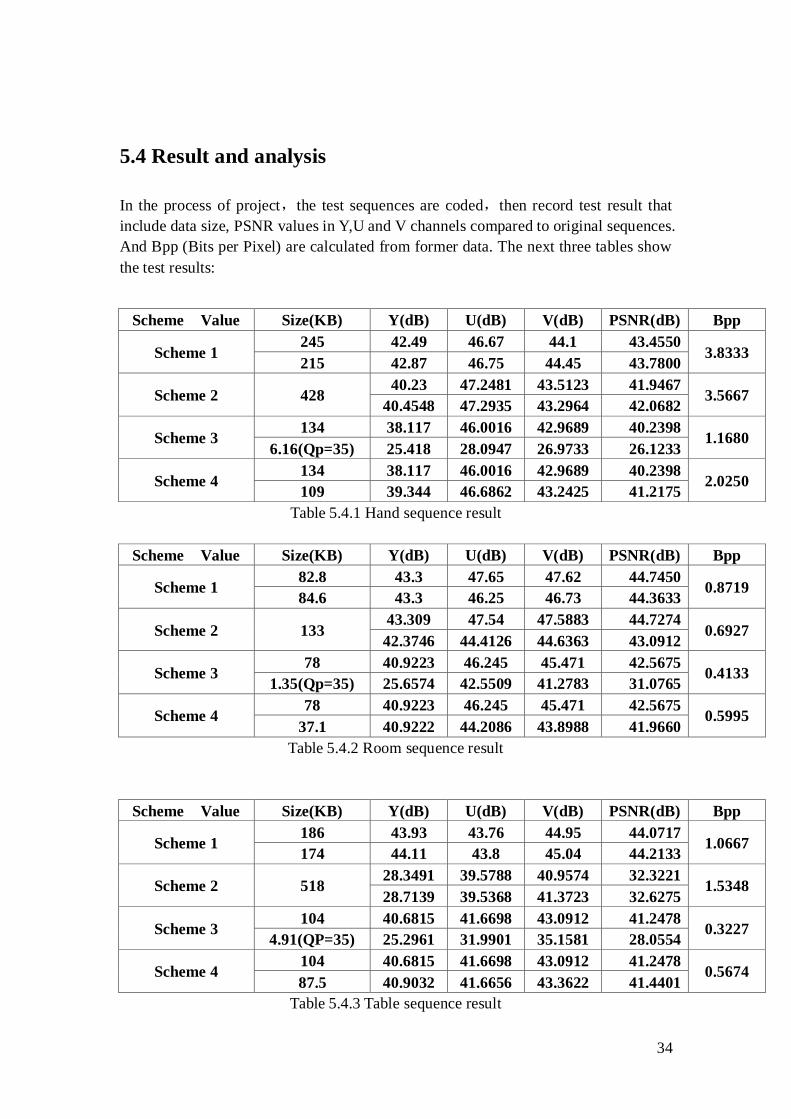
5.4 Result and analysis
In the process of project,the test sequences are coded,then record test result that
include data size, PSNR values in Y,U and V channels compared to original sequences.
And Bpp (Bits per Pixel) are calculated from former data. The next three tables show
the test results:
Scheme Value Size(KB) Y(dB) U(dB) V(dB) PSNR(dB) Bpp
Scheme 1 245 42.49 46.67 44.1 43.4550
3.8333 215 42.87 46.75 44.45 43.7800
Scheme 2 428 40.23 47.2481 43.5123 41.9467
3.5667 40.4548 47.2935 43.2964 42.0682
Scheme 3 134 38.117 46.0016 42.9689 40.2398
1.1680 6.16(Qp=35) 25.418 28.0947 26.9733 26.1233
Scheme 4 134 38.117 46.0016 42.9689 40.2398
2.0250 109 39.344 46.6862 43.2425 41.2175
Table 5.4.1 Hand sequence result
Scheme Value Size(KB) Y(dB) U(dB) V(dB) PSNR(dB) Bpp
Scheme 1 82.8 43.3 47.65 47.62 44.7450
0.8719 84.6 43.3 46.25 46.73 44.3633
Scheme 2 133 43.309 47.54 47.5883 44.7274
0.6927 42.3746 44.4126 44.6363 43.0912
Scheme 3 78 40.9223 46.245 45.471 42.5675
0.4133 1.35(Qp=35) 25.6574 42.5509 41.2783 31.0765
Scheme 4 78 40.9223 46.245 45.471 42.5675
0.5995 37.1 40.9222 44.2086 43.8988 41.9660
Table 5.4.2 Room sequence result
Scheme Value Size(KB) Y(dB) U(dB) V(dB) PSNR(dB) Bpp
Scheme 1 186 43.93 43.76 44.95 44.0717
1.0667 174 44.11 43.8 45.04 44.2133
Scheme 2 518 28.3491 39.5788 40.9574 32.3221
1.5348 28.7139 39.5368 41.3723 32.6275
Scheme 3 104 40.6815 41.6698 43.0912 41.2478
0.3227 4.91(QP=35) 25.2961 31.9901 35.1581 28.0554
Scheme 4 104 40.6815 41.6698 43.0912 41.2478
0.5674 87.5 40.9032 41.6656 43.3622 41.4401
Table 5.4.3 Table sequence result
35
From what has been showed in the tables above, the first scheme can get the
maximum PSNR value, which means that the received image quality is the best in the
four schemes, but the data size is relatively large. The second program receives the
maximum data size, and the image quality is not the ideal. The third scheme could get
the smallest data size, while PSNR value is also relatively low which means that it
will get relatively poor image quality. The fourth scheme can simultaneously get a
smaller data size and excellent video quality; it is obvious that the fourth scheme is
the best in all the four schemes design. Meanwhile it also needs to mention that the
size of the right channel data is very small in the third scheme, and the reconstructed
video quality is not very bad, but its quality has met the need of transporting video
communications in general.
In HHI database, the PSNR of reconstruction right image produced by left image and
depth map is only 20 more or less, and the value reaches to 30 for the scheme 3
designed in the project. Scheme 3‟s great advantage is that it is easy to increase
multi-viewpoint information without size lager. Since the size of depth map sequence
is almost 20 times smaller than the left sequence. The more viewpoints, the relative
Bpp has more benefits. In practical application, the requirement for human eyes
judging a video quality is between 25 and 30 for PSNR standard, furthermore in
stereo vision, human usually accept the better channel quality as whole stereo video
quality due to psychological causes and the left channel video quality is good enough.
Therefore scheme 3 is still a nice choice for stereo video transmitting.
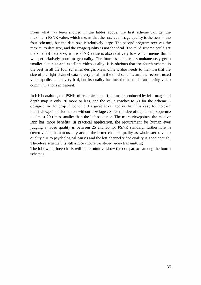
The following three charts will more intuitive show the comparison among the fourth
schemes
36
Figure 5.4.1 Hand sequence PSNR
Figure 5.4.2 Room sequence PSNR
37
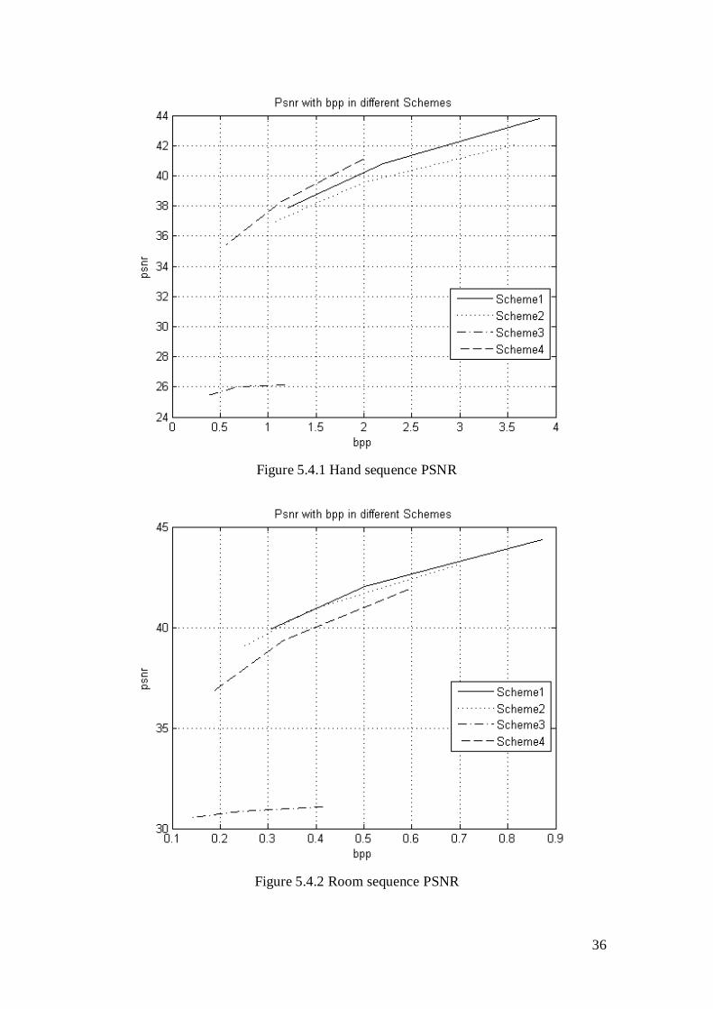
Figure 5.4.3 Table sequence PSNR
From what has been showed above in the three tables, in the results of two sets of
video tests, the fourth scheme is the best, which could get the maximum PSNR value
in the same Bpp situation. But in the sets of Room tests, the best result is the first
scheme. So the video sequence in the different scenes and resolutions, the test result is
not conclusive.
According to the test result, the fourth scheme is the best one which could get a
relatively small data size and ideal video quality.
38
6. Conclusion and Future research
6.1 Conclusion
Previous chapters four kinds of different three-dimensional video encoding schemes
are designed and tested and the experimental data collected for further analysis. We
have selected video sequences taken from different scenes and different motion trace
for the scenery and the camera, as well as different resolution, test platform we
selected the mature test model JM and JMVC, experimental process of rigorous and
realistic, ensuring access to authentic data . Final we design of the research methods
for analyzing the experimental data to a conclusion. Through a comprehensive
consideration of various indicators, the fourth scheme is considered best. However,
what cannot be overlooked is the third method, its excellent compression ratio in the
data size so that it has an absolute advantage, We believe that in the future by
improving its image quality it is possible that this method becomes one of attractive
methods in the field.
6.2 Future research
Although scheme4 has the best performance in this thesis, scheme3 is still potentially
competitive. Because in multi-view case a depth map can be calculated to create any
view which is close to the original view point. In Table 5.4.1, Table 5.4.2 and Table
5.4.3 the right view is actually the depth map. Its size is about 1:22.3, 1:57.7 and
1:21.1 compare to the reference (left view) in three scenes respectively. So when the
stereo view expanded to more views, the overall data size in scheme3 will just be
slightly increased. And it is also very flexible and practical to generate virtual view
points from a precise depth map.
And it‟s necessary to implement the coding and decoding algorithms to the DSP
(digital signal processor). With the capturing, coding, transmitting and decoding
process running without computer, the distributed sensor and monitoring system yet
can be established.
39
7. Reference
[1] Jiandan Chen, A Multi Sensor System for a Human Activities Space Aspects of
Planning and Quality Measurement
[2] Binocular vision, available: http://en.wikipedia.org/wiki/Binocular_vision
[3] Epipolar geometry available: http://en.wikipedia.org/wiki/Epipolar_geometry
[4] Anaglyph image available: http://en.wikipedia.org/wiki/Anaglyph_image
[5] Balamuralii Balasubramaniyam “Stereoscopic Video Coding” A doctoral thesis
submitted in partial fulfilment of the requirements for the degree of Doctor of
Philosophy
[6] Color model available: http://en.wikipedia.org/wiki/Color_model
[7] YUV available: http://en.wikipedia.org/wiki/YUV
[8] Binocular disparity available: http://en.wikipedia.org/wiki/Binocular_disparity
[9]Computing disparity using digital stereo images available:
http://en.wikipedia.org/wiki/Binocular_disparity
[10] Image rectification available: http://en.wikipedia.org/wiki/Image_rectification
[11] M. W. Siegel, P. Gunatilake, S. Sethuraman and A. J. Jordan, "Compression of
stereo image pairs and streams," Proceedings- SPIE, The International Society For
OpticalEngineering, pp. 258-268, 1994.
[12] Standards. Available:
http://en.wikipedia.org/wiki/Video_Coding_Experts_Group#Standards Sep. 2009.
[13] P. Gunatilake, M. Siegel and A. Jordan, "Compression of Stereo Video Streams,”
Signal Processing of HDTV, vol. 10, 1994.
[14] Motion estimation. Available: http://en.wikipedia.org/wiki/Motion_estimation
Sep. 2009.
[15] I. E. G. Richardson, “H.264 and MPEG-4 Video Compression: Video Coding for
Next-Generation Multimedia.” John Wiley & Sons, 2003,
[16] JM main page. Available http://iphome.hhi.de/suehring/tml/ Sep 2009.
[17] JMVC main page. Available http://www.itu.int/ITU-T/index.html Sep 2009.
[18] R. R. Britt. How 3-D works: Mars revealed by human-like eyes. Available

40
http://www.space.com/scienceastronomy/rovers_ 3D_040210.html, Sep 2006.
[ 19] Lili Meng and Yao Zhao, "Stereo video coding based on H.264 with adaptive
prediction mode," Signal Processing, 2008. ICSP 2008. 9th International Conference
on, pp. 1309-1312, 2008.
[20] Tested sequences. Available http://sp.cs.tut.fi/mobile3dtv/stereo-video/ Sep
2009.