designers’guidetoeurocode: basisofstructuraldesign · pdf filedesigners’ guides to...
TRANSCRIPT

DESIGNERS’ GUIDES TO THE EUROCODES
DESIGNERS’ GUIDE TO EUROCODE:BASIS OF STRUCTURAL DESIGNEN 1990
Second edition
H. GULVANESSIAN CBECivil engineering and Eurocode consultant, UK
J.-A. CALGAROCentre des Hautes Etudes de la Construction, France
M. HOLICKYKlokner Institute, Czech Technical University, Czech Republic
Series editorHaig Gulvanessian CBE

Published by ICE Publishing, 40 Marsh Wall, London E14 9TP
Full details of ICE Publishing sales representatives and distributors can be found at:
www.icevirtuallibrary.com/info/printbooksales
First published 2002
Second edition 2012
www.icevirtuallibrary.com
A catalogue record for this book is available from the British Library
ISBN 978-0-7277-4171-4
# Thomas Telford Limited 2012
ICE Publishing is a division of Thomas Telford Ltd, a wholly-owned subsidiary of the Institution of Civil
Engineers (ICE).
Permission to reproduce extracts from EN1990 is granted by BSI. British Standards can be obtained in PDF
or hardcopy formats from the BSI online shop: www.bsigroup.com/shop or by contacting BSI Customer
Services for hardcopies only: Tel.: þ44 (0)20 8996 9001, Email: [email protected].
All rights, including translation, reserved. Except as permitted by the Copyright, Designs and Patents Act
1988, no part of this publication may be reproduced, stored in a retrieval system or transmitted in any form
or by any means, electronic, mechanical, photocopying or otherwise, without the prior written permission of
the Publishing Director, ICE Publishing, 40 Marsh Wall, London E14 9TP.
This book is published on the understanding that the authors are solely responsible for the statements made
and opinions expressed in it and that its publication does not necessarily imply that such statements and/or
opinions are or reflect the views or opinions of the publishers. While every effort has been made to ensure
that the statements made and the opinions expressed in this publication provide a safe and accurate guide,
no liability or responsibility can be accepted in this respect by the authors or publishers.
Typeset by Academic þ Technical, Bristol
Printed and bound by CPI Group (UK) Ltd, Croydon, CR0 4YY
Eurocodes Expert
Structural Eurocodes offer the opportunity of harmonised design standards for the European construction
market and the rest of the world. To achieve this, the construction industry needs to become acquainted
with the Eurocodes so that the maximum advantage can be taken of these opportunities.
Eurocodes Expert is an ICE and Thomas Telford initiative set up to assist in creating a greater awareness
of the impact and implementation of the Eurocodes within the UK construction industry.
Eurocodes Expert provides a range of products and services to aid and support the transition to Eurocodes.
For comprehensive and useful information on the adoption of the Eurocodes and their implementation
process please visit our website or email [email protected]

Designers’ Guide to Eurocode: Basis of Structural DesignISBN 978-0-7277-4171-4
ICE Publishing: All rights reserved
http://dx.doi.org/10.1680/bsd.41714.001
Introduction
The material in this introduction is covered in the foreword to EN 1990, ‘Eurocode: basis ofstructural design’, in clauses on:
g the background to the Eurocode programmeg the status and field of application of the Eurocodesg National standards implementing Eurocodesg links between Eurocodes and harmonised technical specifications (ENs and ETAs) for
productsg additional information specific to EN 1990g National Annexes to EN 1990.
This introduction is also concerned with the implementation and use of the structural Eurocodesin the EU member states. An essential background paper to this is the CEC’s Guidance Paper L(Concerning the Construction Products Directive – 99/106/EEC), Application and Use of Euro-codes (European Commission, 2001). Reference to this paper is made in this introduction. Inaddition, Appendix A of this guide ‘The Construction Products Directive’, gives detailedinformation on the Directive.
The following abbreviations are used in this chapter:
CEC Commission of the European CommunitiesCEN Comite Europeen de Normalisation (European Committee for Standardization)CPD Construction Products DirectiveEFTA European Free Trade AssociationEN EuroNorm (European Standard)ENV EuroNorm Vornorm (European Pre-standard)EOTA European Organisation for Technical ApprovalER Essential RequirementETA European Technical ApprovalETAG European Technical Approval GuidelinesEU European UnionhEN Harmonised European Standard for a construction product (to enable CE marking)ID Interpretative DocumentNDP Nationally Determined ParameterNSB national standard bodyPT Project TeamSC SubcommitteeTC Technical Committee
The following definitions will aid the understanding of this introduction and Appendix A of thisguide:
Approval body. Body authorised to issue ETAs (Article 10 of the CPD); member of the EOTA.
Construction works. Building and civil engineering works.
European Technical Approval (ETA). Favourable technical assessment of the fitness for use of aproduct for an intended use, based on the fulfilment of the ERs for building works for which the
1

product is used (Articles 8, 9 and 4.2 of the CPD). ETA can be issued on the basis of guidelines(Article 9.1 of the CPD) or delivered without guidelines (Article 9.2 of the CPD).
European Technical Approval Guidelines (ETAGs). Document used as the basis of preparingETAs which contain specific requirements for the products within the meaning of the ERs, thetest procedures, the methods of assessing and judging the results of the tests, and the inspectionand conformity procedures, written on the basis of the mandate received by the EOTA from theCommission (Article 11 of the CPD).
National Annex (to an EN Eurocode part). Annex to an EN Eurocode part containing the NDPsto be used for the structural design of buildings and civil engineering works in an EU memberstate. The National Annex is governed by the CEN rules.
National provisions. National laws, regulations and administrative provisions, imposed by alllevels of public authorities, or private bodies acting as a public undertaking or as a publicbody on the basis of a monopoly position.
Nationally Determined Parameter (NDP). A national choice left open in an EN Eurocode aboutvalues (where symbols are given in the EN Eurocodes), a set of classes or alternative procedurespermitted within the EN Eurocodes.
Technical specifications. hENs and ETAs for construction products (Article 4.1 of the CPD).
Structure. Load-bearing construction (i.e. an organised assembly of connected parts designed toprovide mechanical resistance and stability to the works) (ID 1, clause 2.1.1; see Appendix A forcomments on ID 1).
Structural material. Material or constituent product with properties which enter into structuralcalculations or otherwise relate to the mechanical resistance and stability of works and partsthereof, and/or to their fire resistance, including aspects of durability and serviceability.
Structural component. Components to be used as load-bearing part of works designed to providemechanical resistance and stability to the works and/or fire resistance, including aspects ofdurability and serviceability (ID 1, clause 2.1.1 (see Appendix A)).
Structural kit. Kit consisting of structural components to be assembled and installed on site. Theassembled system made from the structural kit is a ‘structure’.
Background to the Eurocode programmeThe objectives of the Eurocodes and their statusIn 1975, the CEC decided on an action programme in the field of construction based on Article 95of the Treaty of Rome. The objective of the programme was the elimination of technical obstaclesto trade and the harmonisation of technical specifications.
Within this action programme the European Commission took the initiative to establish a set ofharmonised technical rules for the structural design of construction works, with the followingobjective:
The Eurocodes to establish a set of common technical rules for the design of buildings andcivil engineering works which will ultimately replace the differing rules in the variousMember States.
For 15 years, the Commission, with the help of a steering committee containing representatives ofEU member states, oversaw the development of the Eurocodes programme, which led to thepublication of a first-generation set of European codes in the 1980s.
In 1989 the special agreement between the CEN and the European Commission transferred thepreparation and publication of the Eurocodes to the CEN, thus providing the Eurocodes with afuture status of European EN standards.
This links, de facto, the Eurocodes with the provisions of all the Council’s Directives and/or theCommission’s decisions dealing with European EN standards, for example:
g The Construction Products Directive (see Appendix A of this guide for a brief descriptionof this Directive)
Designers’ Guide to Eurocode: Basis of Structural Design
2

g Public Procurement Directives, on public works and services for execution, design, etc., ofcivil engineering works.
See also the status of the Eurocodes in this introduction.
All 58 Parts of the Eurocodes described in Appendix B were made available by CEN to nationalstandard bodies by 2010. April 2010 was the date of withdrawal of conflicting national standards.
The Eurocode programmeEN 1990 lists the following structural Eurocodes, each generally consisting of a number of partswhich are in different stages of development at present:
g EN 1990. Eurocode: Basis of structural designg EN 1991. Eurocode 1: Actions on structuresg EN 1992. Eurocode 2: Design of concrete structuresg EN 1993. Eurocode 3: Design of steel structuresg EN 1994. Eurocode 4: Design of composite steel and concrete structuresg EN 1995. Eurocode 5: Design of timber structuresg EN 1996. Eurocode 6: Design of masonry structuresg EN 1997. Eurocode 7: Geotechnical designg EN 1998. Eurocode 8: Design of structures for earthquake resistanceg EN 1999. Eurocode 9: Design of aluminium structures
Each of the structural Eurocodes is produced by separate subcommittees under the guidance andco-ordination of a technical committee (CEN/TC 250). The organisational structure of theEurocode work is shown in Figure 1.
Drafts for the structural Eurocodes and their parts are elaborated by project teams which areselected by the appropriate subcommittee. A project team consists of about six experts, whorepresent their subcommittee. Delegates of the 19 CEN members are represented in CEN/TC 250 and its subcommittees. Voting is in accordance with the rules of the CEN.
Appendix B of this guide lists the 58 parts that make up the Eurocode suite.
Introduction
Figure 1. Organisation of the Eurocode work (HG, Horizontal Group; see text for other abbreviations)
HG Fire Design
HG Bridges Co-ordination Group
CEN/TC 250Structural Eurocodes
Basis of structuraldesign
PT PT PT PT PT PT PT PT PT PT PT PT PT PT PT PT PT PT
PT level
TC level
SC level
SC 2
Design ofconcretestructures
SC 1
Actions onstructures
SC 3
Design ofsteel
structures
SC 4
Design ofcomposite
steel/concretestructures
SC 5
Design oftimber
structures
SC 6
Design ofmasonrystructures
SC 7
Geotechnicaldesign
SC 8
Earthquakeresistance of
structures
SC 9
Design ofaluminiumstructures
3

Potential benefits of the use of the EurocodesThe intended benefits of the Eurocodes include the following:
g to provide a common understanding regarding the design of structure between owners,operators and users, designers, contractors and manufacturers of construction products
g to provide common design criteria and methods to fulfil the specified requirements formechanical resistance, stability and resistance to fire, including aspects of durability andeconomy
g to facilitate the marketing and use of structural components and kits in EU member statesg to facilitate the marketing and use of materials and constituent products the properties of
which enter into design calculations, in EU member statesg to be a common basis for research and development, as the Eurocodes offer the
opportunity for pan-European research for their future editions, leading to substantialsavings in the cost of research
g to allow the preparation of common design aids and softwareg to benefit European civil engineering firms, contractors, designers and product
manufacturers in their world-wide activities, and to increase their competitiveness.
Responsibilities of EU member statesThe layout of EN 1990, and indeed the complete Eurocode suite, takes account of the responsi-bilities of the EU member states, in the implementation of the structural Eurocodes where levelsof safety of buildings and civil engineering works and parts thereof, including aspects ofdurability and economy, remain within the competence of each member state, even after theimplementation of the EN Eurocodes.
Status and field of application of the EurocodesStatus of the EurocodesThe special agreement between the CEN and the European Commission (BC/CEN/03/89)specified that the Eurocodes are intended to serve as reference documents to be recognised byauthorities of the EU member states for the following purposes:
g As a means of compliance of building and civil engineering works with the EssentialRequirements (ERs) as set out in Council Directive 89/106/EEC (the CPD), particularlyER 1 (Mechanical Resistance and Stability) and ER 2 (Safety in Case of Fire). The use ofEN Eurocodes in technical specifications for products is described in the Commission’sguidance paper Application and Use of Eurocodes (European Commission, 2001). It is theobjective to replace the CPD by the Construction Product Regulation (CPR) in 2013. Inthe CPR, ERs will be called Basic Works Requirements (BWRs). BWR 1 to 6 willreplicate ER 1 to 6, but there will be a new requirement: BWR 7 (Sustainable Use ofNatural Resources).
g As a basis for specifying contracts for the execution of construction works and relatedengineering services in the area of public works. This relates to the following CouncilProcurement Directives:– Works Directive 2004/18/EC, which covers procurement by public authorities of civil
engineering and building works, and Utilities Directive 2004/17/EC (operation ofenergy, water, etc.) with a threshold in 2010 of about 4.85 million euros
– Services Directive 2006/132/EC, which covers procurement of services by publicauthorities, with thresholds in 2010 for government departments of 125 000 euros andfor others, including local authorities, of 193 000 euros. The threshold for utilities in2010 was 387 000 euros.
g As a framework for drawing up harmonised technical specifications for construction products.
Relationship with the Interpretative DocumentsThe Eurocodes have a direct relationship with the Interpretative Documents (IDs) referred toin Article 12 of the CPD, although they are of a different nature from harmonised productstandards (see Appendix A of this guide).
According to Article 3.3 of the CPD, the ERs shall be given concrete form in IDs for the creationof the necessary links between the essential requirements and the mandates for hENs and ETAs.
Designers’ Guide to Eurocode: Basis of Structural Design
4

According to Article 12 of the CPD the IDs shall:
g give concrete form to the essential requirements by harmonising the terminology and thetechnical bases and indicating classes or levels for each requirement where necessary
g indicate methods of correlating these classes or levels of requirement with the technicalspecifications, for example, methods of calculation and of proof, and technical rules forproject design
g serve as a reference for the establishment of harmonised standards and guidelines forEuropean technical approval.
The Eurocodes, de facto, play a similar role of the field of the ER 1 (Mechanical Resistance andStability) and a part of ER 2 (Safety in Case of Fire).
Therefore, technical aspects arising from the Eurocodes have to be taken into account by CENtechnical committees, EOTA working groups and EOTA bodies working on product specifica-tions, with a view to achieve full compatibility between the product specifications and the ENEurocodes. For a full explanation see the paper Application and Use of Eurocodes (EuropeanCommission, 2001).
Field of application of the EurocodesThe structural Eurocodes provide Principles and Rules of Application for the design of:
g whole structures andg component products
of both traditional and innovative nature.
However, unusual forms of construction (e.g. use of certain materials) or design conditions(extreme hazards, e.g. large external explosions) are not fully covered, and additional expertguidance will be required in such situations.
National standards implementing EurocodesIt is the responsibility of each NSB (e.g. the British Standards Institute (BSI) in the UK, theAssociation Francaise de Normalisation (AFNOR) in France, the Deutsche Institut furNormung (DIN) in Germany, and the Ente Nazionale Italiano di Unificazione (UNI) in Italy)to implement EN 1990 as a national standard.
The national standard implementing EN 1990 (and the national standards implementing eachEurocode part) will comprise, without any alterations, the full text of the Eurocode and itsannexes as published by the CEN. This may be preceded by a National Title Page, and by aNational Foreword, and may be followed by a National Annex (Figure 2).
Introduction
Figure 2. National standard implementing a Eurocode
a
b
c
d
e
f
a: National Title Page
b: National Foreword
c: EN Title Page
d: EN text
e: EN Annex(es)
f: National Annex
5

National AnnexesAs already stated in this introduction, EN 1990 recognises the responsibility of regulatoryauthorities (e.g. the building regulations division of the department for Transport, Local Govern-ment and the Regions (DTLR) in the UK) or National Competent Authorities (e.g. theHighways Agency in the UK) in each EU member state, and it has safeguarded their right todetermine values related to safety matters at national level where these continue to vary fromstate to state, through a National Annex.
Possible differences in geographical or climatic conditions (e.g. wind or snow maps) or in ways oflife, as well as different levels of protection that may prevail at national, regional or local level,will be taken into account, by choices left open about values, classes, or alternative methods,identified in the EN Eurocodes to be determined nationally.
These values, classes or methods to be chosen or determined at national level, called NationallyDetermined Parameters (NDPs), will allow the EU member states to choose the level of safety,including aspects of durability and economy applicable to works in their territory.
The NSBs should publish a National Annex, on behalf of and with the agreement of the NationalCompetent Authorities. A National Annex is not required if the EN Eurocode part is notrelevant for the member state (e.g. seismic design for some countries).
The National Annex may only contain, directly or by reference to specific provisions, informa-tion on those parameters which are left open in the Eurocodes for national choice, the NDPs, tobe used for the design of buildings and civil engineering works to be constructed in the countryconcerned, that is:
g values and/or classes where alternatives are given in the Eurocodeg values to be used where only a symbol is given in the Eurocodeg country-specific data (geographical, climatic, etc.), such as snow mapsg procedures to be used where alternative procedures are given in the Eurocode.
The National Annex may also contain the following:
g decisions on the application of informative annexesg references to non-contradictory complementary information to assist the user in applying
the Eurocode.
A National Annex cannot change or modify the content of the EN Eurocode text in any wayother than where it indicates that national choices may be made by means of NDPs.
In EN 1990, for example, all partial factors are given as symbols, with recommended values forthe symbols given in notes (see Chapter 7 of this guide). The National Annex may either adoptthe recommended values or give alternative values.
In addition, EN 1990 gives alternative procedures for the load combination expressions, anddifferent approaches for treating soil–structure interaction (see Chapters 6 and 7). Here, theNational Annex needs to make a choice as to the approach to be used nationally.
Each EU member state will have a different National Annex – the National Annex used must bethe one applicable to where the building or civil engineering work is being constructed. Forexample, a UK designer will have to use EN 1990 with the UK National Annex when designinga building in the UK. The same designer, designing a building in Italy, will have to use EN 1990with the Italian National Annex.
Links between Eurocodes and harmonised technical specifications(ENs and ETAs) for productsThere is a need for consistency between the technical specifications for construction products(hENs and ETAs) and the technical rules for works.
For construction products, which contribute to the mechanical resistance and stability of works,two types of properties are distinguished, according to the validation method:
Designers’ Guide to Eurocode: Basis of Structural Design
6

g properties determined by testing (generally in the case of structural materials and products:concrete, reinforcing steel for concrete, structural steel, etc.)
g properties determined by calculation following methods given by the Eurocodes, which arealso used for the structural design of works (generally in the case of prefabricatedstructural components and kits, such as prefabricated concrete components, prefabricatedstairs, timber frame buildings kits, etc.).
For both types of product properties the resulting values are ‘declared’ in the information accom-panying the CE marking of the product and used in the structural design of works or partsthereof.
As a consequence, for the consideration or use of EN Eurocodes in harmonised product specifi-cations and ETAGs distinction is made in the following between:
g materials and constituent products with properties determined by testingg structural components or kits with properties calculated according to EN Eurocode
methods.
Additional information specific to EN 1990Technical objectives of EN 1990EN 1990 describes the principles and requirements for safety, serviceability and durabilityof structures and is intended to be used for direct application with ‘Eurocode 1: Actions onstructures’ and the design Eurocodes (Eurocodes 2 to 9).
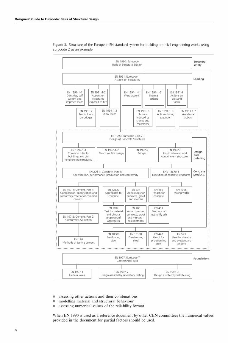
Figure 3 shows the structure of the European standards system for building and civil engineeringworks, using ‘Eurocode 2: Design of concrete structures’, as an example.
In addition, EN 1990 provides guidelines for the aspects of structural reliability relating to safety,serviceability and durability for design cases not covered by the Eurocodes (e.g. other actions,other materials and types of structures not treated), and to serve as a reference document forother CEN committees concerned with structural engineering aspects.
Layout and organisation of EN 1990The layout of EN 1990, to aid usability, is as follows:
g Sections 1 to 6 of EN 1990 are applicable to all types of construction works within thefields of application of the structural Eurocodes defining requirements and criteria.
g Separate normative annexes (e.g. Annex A1, ‘Application for buildings’) which arederivations from the general sections specific for each structural type (e.g. buildings,bridges, towers and masts).
g Informative specialist annexes applicable to all structures.
Intended users of EN 1990EN 1990 is intended for the consideration of more categories of users than are the other Euro-codes. It lists the intended users as:
g standard drafting committees for both structural design and related products, testing andexecution standards
g clients, for the specific requirements on reliability levels and durabilityg designersg contractorsg relevant authorities.
Each of these users will have a different perspective on the provisions of EN 1990.
Intended uses of EN 1990EN 1990 is intended for the design of structures within the scope of the Eurocodes (see Chapter 1).Additionally, it can be used as a guidance document in the design of structures outside the scopeof the Eurocodes for:
Introduction
7
g assessing other actions and their combinationsg modelling material and structural behaviourg assessing numerical values of the reliability format.
When EN 1990 is used as a reference document by other CEN committees the numerical valuesprovided in the document for partial factors should be used.
Designers’ Guide to Eurocode: Basis of Structural Design
Figure 3. Structure of the European EN standard system for building and civil engineering works using
Eurocode 2 as an example
EN 1991-1-1Densities, selfweight and
imposed loads
EN 1991-1-2Actions onstructures
exposed to fire
EN 1991-2Traffic loadson bridges
EN 1991-1-3Snow loads
EN 1991-3Actions
induced bycranes andmachinery
EN 1991-1-6Actions during
execution
EN 1991-1-7Accidental
actions
EN 1991-1-4Wind actions
EN 1991-1-5Thermalactions
EN 1991-4Actions onsilos and
tanks
EN 1992-1-1Common rules forbuildings and civil
engineering structures
EN 1992-3Liquid retaining and
containment structures
EN 1992-1-2Structural Fire design
EN 1992-2Bridges
EN 1097Test for material
and physicalproperties ofaggregates
EN 480Admixtures forconcrete, groutand mortars –test methods
EN 451Methods of
testing fly ash
EN 206-1: Concrete. Part 1:Specification, performance, production and conformity
ENV 13670-1Execution of concrete structures
EN 197-1: Cement. Part 1:Composition, specification andconformity criteria for common
cements
EN 12620Aggregates for
concrete
EN 934Admixtures forconcrete, grout
and mortars
EN 450Fly ash forconcrete
EN 1008Mixing water
EN 10080Reinforcing
steel
EN 10138Pre-stressing
steel
EN 447Grout for
pre-stressingsteel
EN 523Steel for sheathsand prestandard
tendons
EN 197-2: Cement. Part 2:Conformity evaluation
EN 196Methods of testing cement
EN 1990: EurocodeBasis of Structural Design
EN 1991: Eurocode 1Actions on Structures
Structuralsafety
Designanddetailing
Loading
Concreteproducts
EN 1997-1General rules
EN 1997-2Design assisted by laboratory testing
EN 1997-3Design assisted by field testing
Foundations
EN 1992: Eurocode 2 (EC2)Design of Concrete Structures
EN 1997: Eurocode 7Geotechnical data
8

National Annex for EN 1990EN 1990 allows national choice through a number of clauses in Annex A1 of EN 1990, ‘Applica-tion for Buildings’. The choice relates mainly to selecting partial factor and combinationcoefficients where symbols (together with recommended values) are given, and where alternativeprocedures are given.
A national standard implementing EN 1990 should have a National Annex containing all NDPsto be used for the design of construction works in the relevant country.
The clauses of EN 1990 where national choice is allowed is listed in the foreword of EN 1990.
Appendix D of this guide gives the names and addresses of the appropriate national standardorganisations to whom enquiries may be made with regard to the availability of NationalAnnexes for a particular country.
REFERENCE
European Commission (2001) Guidance Paper L (Concerning the Construction Products Directive –
89/106/EEC). Application and Use of Eurocodes. EC, Brussels.
Introduction
9

Preface
EN 1990, ‘Eurocode: basis of structural design’, is the head document of the Eurocode suite, anddescribes the principles and requirements for safety, serviceability and durability of structures,and is intended to be used for direct application with ‘Eurocode 1: Actions on structures’ andthe design Eurocodes 2 to 9. As such, it is the key Eurocode document.
Aims and objectives of this guideThe principal aim of this book is to provide the user with guidance on the interpretation and useof EN 1990. The guide also provides information on the implementation of the Eurocodes andtheir use with regard to National Annexes. In producing this guide the authors have endeavouredto provide explanations and commentary to the clauses in EN 1990 for all the categories of usersidentified in the foreword of the Eurocode. Although the design Eurocodes are primarilyintended for the design of buildings and civil engineering works, EN 1990 is intended for theconsideration of more categories of users who include:
g designers and contractors (as for the other Eurocodes), plusg code-drafting committeesg clientsg public authorities and other bodies who produce regulations.
Layout of this guideEN 1990 has a foreword and six sections together with four annexes. This guide has anintroduction which corresponds to the foreword of EN 1990, and Chapters 1 to 6 of the guidecorrespond to Sections 1 to 6 of the Eurocode. Chapters 7 to 10 correspond to Annexes A, B,C and D of the Eurocode, respectively. The numbering of sections in this guide also correspondsto those in EN 1990; for example, Section 7.2 of the guide corresponds to clause A.2 of EN 1990,and Section 6.4 is a commentary to clause 6.4 of the Eurocode. All cross-references in this guideto sections, clauses, subclauses, annexes, figures and tables of EN 1990 are in italic type. Thenumbers for the expressions correspond unless prefixed by D (D for Designers’ Guide).Expressions prefixed by D do not appear in EN 1990. Where text from a clause of EN 1990has been directly reproduced, this is also shown in italics.
This handbook has two types of appendix. Particular chapters may have their own appendiceswhich provide further explanation to particular clauses; there, appendices may be of interestonly to a particular category of user. Where background is given, this is in a box. These arereferred to, for example, as Appendix 1 to Chapter 4. There are also four main appendices (Ato D) provided as separate chapters which provide background and useful advice relating tothe whole guide and should be of interest to all categories of users.
AcknowledgementsThis book would not have been possible without the successful completion of EN 1990. Thoseinvolved in the process included:
g The Project Team, consisting of Professor H. Gulvanessian (convenor), Professor G. Augusti,Professor J.-A. Calgaro; Dr B. Jensen, Dr P. Luchinger and Mr P. Spehl; and the twopermanently invited experts to the Project Team, Mr T. Hagberg and Professor G. Sedlacek.
g Before the Project Team was formed, the foundations of the conversion werelaid by the CEN/TC250 Basis of Design Ad-hoc Group, which consisted ofProfessor H. Gulvanessian (convenor), Professor J.-A. Calgaro, Professor J. Grunberg,Mr T. Hagberg, Dr P. Luchinger and Mr P. Spehl.
g Particular members of the ‘Eurocode 7: Geotechnical design’ committees for contributingto the clauses in EN 1990 relating to soil–structure interaction, in particular ProfessorR. Frank, the Chairman of CEN/TC 250/SC 7.
v

g Those who advised on the translation of EN 1990 into French or German, and thosewho advised on the final editing, in particular Mr H. Mathieu, Professor Ziebke,Mr B. Haseltine, Professor J. Mills and Mr C. Taylor.
g National delegations to CEN/TC 250, and the national technical contacts, for theirvaluable and constructive comments.
g The two former chairmen of CEN/TC 250 Dr G. Breitschaft and Mr D. Lazenby, and thepresent chairman, Professor H. Bossenmeyer, whose advice was essential during theproduction of EN 1990.
g Professor L. Ostlund, Professor A. Vrouwenvelder and Mr R. Lovegrove for their adviceand help to the project team.
g Professor H. Gulvanessian’s personal assistant, Mrs C. Hadden, who gave considerablesecretarial support of outstanding quality, both in the preparation of EN 1990 and for thisguide.
This book is dedicated to all those mentioned above, and to:
g The authors’ wives, Vera Gulvanessian, Elizabeth Calgaro and Nadia Holicka, for theirsupport and patience.
g The authors’ employers BRE Garston, Watford; SETRA, Paris; and the KlocknerInstitute, Czech Technical University, Prague.
H. Gulvanessian CBEJ.-A. CalgaroM. Holicky
vi

Contents
Preface v
Aims and objectives of this guide vLayout of this guide vAcknowledgements v
Introduction 1
Chapter 1 General 11
1.1. Scope 111.2. Normative references 121.3. Assumptions 121.4. Distinction between Principles and Application Rules 131.5. Terms and definitions 141.6. Symbols 15Appendix: alphabetical index of definitions 15References 16
Chapter 2 Requirements 19
2.1. Basic requirements 192.2. Reliability management 232.3. Design working life 252.4 Durability 272.5. Quality management 29References 31
Chapter 3 Principles of limit states design 33
3.1. General 333.2. Design situations 353.3. Ultimate limit states 363.4. Serviceability limit states 383.5. Limit state design 39
Chapter 4 Basic variables 41
4.1. Actions and environmental influences 414.2. Material and product properties 504.3. Geometrical data 52Appendix 1: modelling of material properties 52Appendix 2: basic statistical techniques for determination of thecharacteristic value 54Example 4.1 57Appendix 3: characteristics of geometrical quantities 58Example 4.2 59Appendix 4: tolerances for the overall imperfections 60
Chapter 5 Structural analysis and design assisted by testing 63
5.1. Structural analysis 635.2. Design assisted by testing 67
Chapter 6 Verification by the partial factor method 69
6.1. General 696.2. Limitations 706.3. Design values 706.4. Ultimate limit states 76
vii

6.5. Serviceability limit states 84Further reading 85
Chapter 7 Annex A1 (normative) – Application for buildings 87
7.1. Field of application 877.2. Combinations of actions 877.3. Ultimate limit states 897.4. Serviceability limit states 101Example 7.1: Ultimate limit states EQU and combined limit states EQU/STR 104Example 7.2: Example of a spread foundation 110Example 7.3: STR limit states in a continuous beam 111Example 7.4: STR limit states in a framed structure 113Appendix: vibration considerations for serviceability limit states 116References 117Further reading 117
Chapter 8 Management of structural reliability for construction works 119
8.1. Scope and field of application 1198.2. Symbols 1198.3. Reliability differentiation 1208.4. Design supervision differentiation 1258.5. Inspection during execution 1268.6. Partial factors for material properties 128References 128Further reading 128
Chapter 9 Basis for partial factor design and reliability analysis 129
9.1. Scope and field of application 1299.2. Symbols 1299.3. Introduction 1309.4. Overview of reliability methods 1309.5. Reliability index � 130Example 9.1 132Example 9.2 133Example 9.3 1339.6. Target value of the reliability index � 1349.7. Approach to calibration of design values 134Example 9.4 134Example 9.5 136Example 9.6 1379.8. Reliability verification formats in Eurocodes 138Example 9.7 1389.9. Partial factors in EN 1990 1399.10. 0 factors 140Example 9.8 141Appendix: Mathcad sheets for example calculations 142Reference 150Further reading 150
Chapter 10 Design assisted by testing 151
10.1. Scope and field of application 15110.2. Symbols 15110.3. Types of test 15110.4. Planning of tests 15210.5. Derivation of design values 15310.6. General principles for statistical evaluations 15310.7. Statistical determination of a single property 15410.8. Statistical determination of resistance models 154Further reading 160
viii

Appendix A The Construction Products Directive (89/106/EEC) 161
Compliance with the structural Eurocodes and the Construction ProductDirective 161The Construction Products Directive 161The essential requirements 161Methods of satisfying the essential requirements 163ID 1: Mechanical resistance and stability 163Category A standards 164
Appendix B The Eurocode suite 165
Appendix C Basic statistical terms and techniques 167
General 167Populations and samples 167Normal and log-normal distributions 169Statistical methods 171Estimation of fractiles 173Example C.1 178References 179
Appendix D National standard organisations 181
CEN national members 181
Index 185
ix

Designers’ Guide to Eurocode: Basis of Structural DesignISBN 978-0-7277-4171-4
ICE Publishing: All rights reserved
http://dx.doi.org/10.1680/bsd.41714.011
Chapter 1
General
This chapter is concerned with the general aspects of EN 1990. The material described in thischapter is covered in Section 1, in the following clauses:
g Scope Clause 1.1g Normative references Clause 1.2g Assumptions Clause 1.3g Distinction between Principles and Application Rules Clause 1.4g Terms and definitions Clause 1.5g Symbols Clause 1.6
1.1. Scope1.1.1 Primary scopeEN 1990, ‘Eurocode: basis of structural design’, is the head document in the Eurocode suite, andit establishes for all the structural Eurocodes the principles and requirements for safety, service-ability and durability of structures; it further describes the basis of design and verification andprovides guidelines for related aspects of structural reliability.
Most importantly, in addition to establishing the principles and requirements it provides the basisand general principles for the structural design of buildings and civil engineering works (includinggeotechnical aspects, structural fire design and situations involving earthquakes, execution andtemporary structures) and is intended to be used in conjunction with EN 1991 to EN 1999.
EN 1990, alone within the Eurocode suite, gives all the operative material independent rules (e.g.partial factors for actions, load combination expressions for ultimate and serviceability limitstates), and therefore EN 1992 to EN 1999, which do not provide material independentguidance, cannot be used without EN 1990.
Figure 1.1 shows the structure and links of the Eurocodes.
1.1.2 Scope in relation to design cases not covered by the EurocodesSome of the principles of EN 1990 may be used for the design of special construction works (e.g.nuclear installations, dams) but provisions other than those provided by the Eurocodes willprobably be necessary, in particular for determining specific actions, and for specific additionalrequirements.
As already covered in the introduction in the section ‘Additional information specific toEN 1990’, EN 1990 can be used for the aspects of structural reliability relating to safety, service-ability and durability for design cases outside the scope of the Eurocodes, for example:
g assessing actions not covered by EN 1991 and their combinationsg modelling materials not covered by the Eurocodes (e.g. new and innovative materials,
glass), and their structural behaviourg assessing numerical values of reliability elements (e.g. partial factors and combination
factors, not covered by EN 1990 to EN 1999).
1.1.3 Scope in relation to structural design for execution stage and temporarystructures
EN 1990 is also applicable to the structural design for the execution stage and to temporary (or
Clause 1.1(1)
Clause 1.1(2)
Clause 1.1(2)
Clause 1.1(3)
Clause 1.1(2)
11

Clause 1.1(4)
Clause 1.2
Clause 1.3(1)
Clause 1.3(2)
auxiliary) structures. Further information can be found for the execution stage in EN 1991-1-6(Actions during Execution), and in Annexes A and B of EN 1990 and Chapters 7 and 8 of thisguide for temporary structures.
1.1.4 Scope in relation to assessment of existing constructionEN 1990 is applicable for the structural appraisal of existing construction, for the design ofrepairs and alterations or for assessing changes of use. However, clause 1.1(4) does recognisethat additional or amended rules and provisions might be necessary where appropriate. Forexample, the material properties used in the assessment should be estimated using measured(actual) material properties of the existing structure, which may include statistical techniques,and additional guidance will be required for this.
There are no current CEN codes or standards that directly apply for the appraisal of existingstructures. There is, however, an ISO standard, ISO 13822, ‘Basis of design of structures –assessment of existing structures’ (ISO, 2001), which gives additional and amended provisionsthat may be used with EN 1990.
Currently in the UK, the Building Regulations suggest that guidance can be obtained from theInstitution of Structural Engineers’ publication Appraisal of Existing Structures (Institution ofStructural Engineers, 1980), and BRE Digest 366 (Building Research Establishment, 1991).Guidance is also available in several countries, for example, Switzerland (Societe Suisse des Inge-nieurs et des Architectes, 1994) and the Czech Republic (Czech Office for Standards, Metrologyand Testing, 1987).
1.2. Normative referencesNo comment is necessary.
1.3. Assumptions‘A design which employs the Principles and Application Rules is deemed to meet the requirements ofEN 1990, provided the following assumptions are satisfied.’
The assumptions that need to be satisfied (clause 1.3(2)) are:
g ‘The choice of the structural system and the design of a structure is made by appropriatelyqualified and experienced personnel.’
g ‘Execution is carried out by personnel having the appropriate skill and experience.’Annex B of EN 1990 (see Chapter 8 of this guide) provides additional guidance with regardto ‘appropriately qualified and experienced personnel’, mentioned in assumptions 1 and 2.
Designers’ Guide to Eurocode: Basis of Structural Design
Figure 1.1. Links between the Eurocodes
Links between Eurocodes
Structural safety,serviceability and
durability
Geotechnical andseismic design
Actions on structures
Design and detailing
EN 1990
EN 1991
EN 1997 EN 1998
EN 1992 EN 1993 EN 1994
EN 1995 EN 1996 EN 1999
12

g ‘Adequate supervision and quality control is provided during execution of the work, i.e. indesign offices, factories, plants, and on site.’Annex B of EN 1990 also gives guidance on ‘adequate supervision and quality control’,mentioned in assumption 3, which is based upon the assumed consequences of failure andexposure of the construction works to hazards.
g ‘The construction materials and products are used as specified in EN 1990, and ENs 1991 to1999 or in the relevant supporting material or product specifications.’With regard to assumption 4 it is the intention for the material Eurocodes together withEN 1990 and EN 1991, and their supporting standards, to be grouped into appropriatepackages and used together. A package contains the Eurocode parts that have to be usedfor designing a particular type of structure. For example, a concrete building package willbe EN 1990, EN 1991-1-1 to EN 1991-1-7, EN 1992-1-1 and EN 1992-1-2, EN 1997-1 andthe appropriate parts of EN 1998 (in all, about 14 parts of the Eurocodes). Packages fordifferent types of structures and materials are described in Guidance Paper L (EuropeanCommission, 2001). In the case of new and innovative materials, the principles of EN 1990are assumed to be used.
g ‘The structure will be adequately maintained.’g ‘The structure will be used in accordance with the design assumptions.’
Assumptions 5 and 6 relate to the responsibilities of the owner/user, who must be aware ofhis or her responsibilities regarding a maintenance regime for the structure, and ensuringno overloading takes place. The designer of the structure should recommend amaintenance regime, and state the assumptions made on loading (e.g. maximum loads,removal of snow, etc.) for the design, to the owner.
Depending upon the complexity of the construction works to be designed and executed, assump-tions 1 to 6 may need to be supplemented.
1.4. Distinction between Principles and Application RulesThe clauses in EN 1990 are set out as either Principles or Application Rules:
g ‘Principles comprise general statements for which there is no alternative and requirements andanalytical models for which no alternative is permitted unless specifically stated.’
g ‘Principles are distinguished by the prefix ‘P’ following the paragraph number’. The verb‘shall’ is always used in the Principle clauses.
g ‘Application rules are generally acceptable methods, which follow the principles and satisfytheir requirements.’
g ‘Alternative rules to those given in EN 1990 are permissible provided that it can bedemonstrated that they comply with the principles and are at least equivalent with regard tothe structural safety, serviceability and durability which would be expected when using theEurocode clause.’
EN 1990 through a note to clause 1.4(5) states:
If an alternative rule is substituted for an application rule, the resulting design cannot beclaimed to be wholly in accordance with EN 1990 although the design will remain inaccordance with the Principles of EN 1990. When EN 1990 is used in respect of a propertylisted in an Annex Z of a product standard or an ETAG (European Technical ApprovalGuidelines), the use of an alternative design rule may not be acceptable for CE marking.
With regard to the note to clause 1.4(5), the European Commission guidance paper Applicationand Use of the Eurocodes (European Commission, 2001) states:
National Provisions should avoid replacing any EN Eurocode provisions, e.g. ApplicationRules, by national rules (codes, standards, regulatory provisions, etc.).
When, however, National Provisions do provide that the designer may – even after the endof the co-existence period – deviate from or not apply the EN Eurocodes or certainprovisions thereof (e.g. Application Rules), then the design will not be called ‘a designaccording to EN Eurocodes’.
Clause 1.4(1)
Clause 1.4(2)
Clause 1.4(3)
Clause 1.4(4)
Clause 1.4(5)
Chapter 1. General
13

Clause 1.4(6)
Clause 1.5
Clause 1.5
Clause 1.5.3.1
Clause 1.5.2.16
Clause 1.5.2.15
Clause 1.5.3.2
Clause 1.5.6
Clause 1.5.2.4
Clause 1.5.2.9
Clause 1.5.2.12
The Principles and Application Rules format was originally chosen for the Eurocodes toencourage innovation, where an engineer could consider using different individual rules ofapplication (e.g. based on new research, testing) where he felt innovation was being stifled bythe Eurocodes. Although this is workable for an individual design for a construction works, itcould cause problems when the Eurocode is being used to design a product so that it may begranted CE marking.
‘Application rules are identified by a number in brackets only.’ The verb ‘should’ is normally usedfor Application Rules. The verb ‘may’ is also used, for example, as an alternative ApplicationRule. The verbs ‘is’ and ‘can’ are used for a definitive statement or as an ‘assumption’.
1.5. Terms and definitionsMost of the definitions given in EN 1990 derive from ISO 8930 (ISO, 1987). EN 1990 provides alist of terms and definitions which are applicable to EN 1990 to EN 1999, thus ensuring acommon basis for the Eurocode suite.
With regard to the definitions in clause 1.5 there are significant differences from usages in currentnational codes and standards (e.g. definitions in British codes), to improve precision of meaningand to facilitate translation into other European languages.
For the Eurocode suite, attention is drawn to the following key definitions which may be differentfrom current national practices:
g ‘action’ means a load, or an imposed deformation (e.g. temperature effects or settlement)g ‘strength’ is a mechanical property of a material, in units of stressg ‘resistance’ is a mechanical property of a component or a cross-section of a member, or a
member or structureg ‘effects of actions’ are internal moments and forces, bending moments, shear forces and
deformations caused by actions.
The definitions given in EN 1990 are subdivided into the following clauses:
g clause 1.5.1: ‘Common terms used in the structural Eurocodes’g clause 1.5.2: ‘Special terms relating to design in general’g clause 1.5.3: ‘Terms relating to actions’g clause 1.5.4: ‘Terms relating to material properties’g clause 1.5.5: ‘Terms relating to geometric data’g clause 1.5.6: ‘Terms relating to structural analysis.
The definitions contained in clause 1.5.6 on structural analysis may not necessarily relate to termsin EN 1990, but have been included in the head Eurocode to ensure a harmonisation of termsrelating to structural analysis for EN 1991 to EN 1999.
However, the definitions are difficult to locate even in the subparagraphs as they are not listedalphabetically. To help the reader, an alphabetical list referencing the clauses for a particulardefinition is provided in an appendix to this chapter.
The following comments are made to help the understanding of particular definitions. Mostcomments are made taking into account the definitions provided in ISO 2394, ‘General principleson reliability for structures’ (ISO, 1998). Where no alternative is provided, the definition inEN 1990 accords with or is very similar to that in ISO 2394.
g Clause 1.5.2.4: ‘persistent design situation’. This definition generally refers to conditions ofnormal use. Normal use includes wind, snow and imposed loads likely to occur during theworking life, which may be taken as equal to 50 years for common buildings.
g Clause 1.5.2.9: ‘hazard’. Another example is: gross human errors during design andexecution are frequently occurring hazards.
g Clause 1.5.2.12: ‘limit states’. The note for the definition from ISO 2394, ‘A specified set ofstates which separate desired states from undesired states’, complements the definitionprovided in EN 1990.
Designers’ Guide to Eurocode: Basis of Structural Design
14

g Clause 1.5.2.14: ‘serviceability limit state’. The definition from ISO 2394, ‘A limit stateconcerning the criteria governing function related to normal use’, complements thedefinition provided in EN 1990.
g Clause 1.5.2.20: ‘maintenance’. With regard to the definition, ‘working life’ is the actualphysical period of the structure during which it is used for an intended purpose withanticipated maintenance while the ‘design working life’ (clause 1.5.2.8) is an assumedperiod.
g Clause 1.5.3.18: ‘quasi-permanent value of a variable action’. The part of the EN 1990definition ‘for which will be exceeded is a large fraction of the reference period’, is given inthe latest draft of ISO 2394 as ‘during which it is exceeded is of the magnitude half theperiod’. The ISO definition is only applicable to buildings.
g Clause 1.5.4.1: the ISO 2394 definition complements the EN 1990 definition.‘Characteristic value of a material property’: an a priori specified fractile of the statisticaldistribution of the material property in the supply produced within the scope of therelevant material standard.
1.6. SymbolsThe notation in clause 1.6 is based on ISO 3898 (ISO 1997).
With regard to the notation for actions it has already been stated that actions refer not only toforces directly applied to the structure but also to imposed deformations. Actions are furthersubdivided as permanent (G) (self-weight), variable Q (imposed loads, snow loads, etc.) andaccidental actions (A) and seismic actions (AE).
Characteristic values of any parameter are distinguished by the subscript ‘k’. Design values havethe subscript ‘d’. The subscript ‘inf ’ refers to lower value of a characteristic or design value of anaction or a material property, while the subscript ‘sup’ refers to the upper value.
Appendix: alphabetical index of definitionsThe clause in which a term is defined is given in parentheses.
Accidental action, A Clause 1.5.3.5Accidental design situation Clause 1.5.2.5Accompanying value of a variable action, Qk Clause 1.5.3.19Action, F Clause 1.5.3.1Basic variable Clause 1.5.2.19Characteristic value of an action, Fk Clause 1.5.3.14Characteristic value of a geometrical property, ak Clause 1.5.5.1Characteristic value, Xk or Rk Clause 1.5.4.1Combination of actions Clause 1.5.3.22Combination value of a variable action, 0Qk Clause 1.5.3.16Construction material Clause 1.5.1.5Construction works Clause 1.5.1.1Design criteria Clause 1.5.2.1Design situations Clause 1.5.2.2Design value of an action, Fd Clause 1.5.3.21Design value of a geometrical property, ad Clause 1.5.5.2Design value of a material or product property, Xd or Rd Clause 1.5.4.2Design working life Clause 1.5.2.8Dynamic action Clause 1.5.3.12Effect of action, E Clause 1.5.3.2Elasto-plastic analysis (first or second order) Clause 1.5.6.10Execution Clause 1.5.1.11Fire design Clause 1.5.2.6First-order elastic–perfectly plastic analysis Clause 1.5.6.8First-order linear-elastic analysis without redistribution Clause 1.5.6.3First-order linear-elastic analysis with redistribution Clause 1.5.6.4First-order non-linear analysis Clause 1.5.6.6Fixed action Clause 1.5.3.8
Clause 1.5.2.14
Clause 1.5.2.20
Clause 1.5.2.8
Clause 1.5.3.18
Clause 1.5.4.1
Clause 1.6
Clause 1.5
Chapter 1. General
15
Form of structure Clause 1.5.1.8Free action Clause 1.5.3.9Frequent value of a variable action 1Qk Clause 1.5.3.17Geotechnical action Clause 1.5.3.7Global analysis Clause 1.5.6.2Hazard Clause 1.5.2.9Irreversible serviceability limit states Clause 1.5.2.14.1Limit states Clause 1.5.2.12Load arrangement Clause 1.5.2.10Load case Clause 1.5.2.11Maintenance Clause 1.5.2.20Method of construction Clause 1.5.1.4Nominal value of a material or product property, Xnom or Rnom Clause 1.5.4.3Nominal value Clause 1.5.2.22Permanent action, G Clause 1.5.3.3Persistent design situation Clause 1.5.2.4Quasi-permanent value of a variable action, 2Qk Clause 1.5.3.18Quasi-static action Clause 1.5.3.13Reference period Clause 1.5.3.15Reliability Clause 1.5.2.17Reliability differentiation Clause 1.5.2.18Repair Clause 1.5.2.21Representative value of an action, Frep Clause 1.5.3.20Resistance Clause 1.5.2.15Reversible serviceability limit states Clause 1.5.2.14.2Rigid plastic analysis Clause 1.5.6.11Second-order elastic–perfectly plastic analysis Clause 1.5.6.9Second-order linear-elastic analysis Clause 1.5.6.5Second non-linear analysis Clause 1.5.6.7Seismic action, AE Clause 1.5.3.6Seismic design situation Clause 1.5.2.7Serviceability criterion Clause 1.5.2.14.3Serviceability limit states Clause 1.5.2.14Single action Clause 1.5.3.10Static action Clause 1.5.3.11Strength Clause 1.5.2.16Structural analysis Clause 1.5.6.1Structural member Clause 1.5.1.7Structural model Clause 1.5.1.10Structural system Clause 1.5.1.9Structure Clause 1.5.1.6Transient design situation Clause 1.5.2.3Type of building or civil engineering works Clause 1.5.1.2Type of construction Clause 1.5.1.3Ultimate limit states Clause 1.5.2.13Variable action, Q Clause 1.5.3.4
REFERENCES
Building Research Establishment (1991) Structural Appraisal of Existing Buildings for Change of
Use. BRE, Garston. BRE Digest 366.
Czech Office for Standards, Metrology and Testing (1987) CSN 730038-1988. Navrhovanı a
posuzovanı stagebnıch konstrukcı pri prestavbach [Design and assessment of building structures
subjected to reconstruction]. UNM, Prahe.
European Commission (2001) Guidance Paper L (Concerning the Construction Products Directive –
89/106/EEC). Application and Use of Eurocodes. EC, Brussels.
Institution of Structural Engineers (1980) Appraisal of Existing Structures. Institution of Structural
Engineers, London.
ISO (1987) ISO 8930. General principles on reliability of structures – lists of equivalent terms.
Trilingual edition. ISO, Geneva.
Designers’ Guide to Eurocode: Basis of Structural Design
16

ISO (1997) ISO 3898. Basis of design for structures – notation – general symbols. ISO, Geneva.
ISO (1998) ISO 2394. General principles on the reliability of structures. ISO, Geneva.
ISO (2001) ISO 13822. Basis of design of structures – assessment of existing structures. ISO,
Geneva.
Societe Suisse des Ingenieurs et des Architectes (1994) Evaluation de la Securite Structurale des
Ouvrages Existants. SIA Directive 462. SIA, Zurich.
Chapter 1. General
17

Designers’ Guide to Eurocode: Basis of Structural DesignISBN 978-0-7277-4171-4
ICE Publishing: All rights reserved
http://dx.doi.org/10.1680/bsd.41714.019
Chapter 2
Requirements
This chapter is concerned with basic requirements of EN 1990. The material described in thischapter is covered in Section 2, in the following clauses:
g Basic requirements Clause 2.1g Reliability management Clause 2.2g Design working life Clause 2.3g Durability Clause 2.4g Quality management Clause 2.5
2.1. Basic requirements2.1.1 Principal requirementsThere are four principal fundamental requirements concerning the load-bearing capacity forany structure and structural members. These are covered by clauses 2.1(1)P, 2.1.(2)P, 2.1(3)Pand 2.1(4)P, and may be summarised as follows.
The structure and structural members should be designed, executed and maintained in such a waythat during their intended life with appropriate degrees of reliability and in an economic way theywill:
g withstand actions and influences occurring during their construction and anticipated use(relating to the ultimate limit state requirement) (clause 2.1(1)P)
g meet the specified serviceability requirements for a structure or a structural element(relating to the serviceability limit state requirement) (clause 2.1(1)P)
g have adequate structural resistance, serviceability and durability (clause 2.1(2)P)g have adequate structural resistance for the appropriate required period of time, in case of
fire (clause 2.1(3)P)g not be damaged by events such as explosions, impact or consequences of human errors,
to an extent disproportionate to the original cause (robustness requirement)(clause 2.1(4)P).
The design should consider all of the above requirements since any may be decisive forappropriate structures or structural member. These requirements may be generally interrelatedand partly overlapping.
Structural safety and resistance, serviceability, durability and robustness are the fourcomponents of the structural reliability concept. Figure 2.1 illustrates this concept, which willbe developed in this chapter.
2.1.2 Serviceability and ultimate limit states requirementsThe first two requirements (clause 2.1(1)P), concerning serviceability and ultimate limit statesrequirements in general, are mutually dependent. In many common cases, a structure, whichhas sufficient resistance has also sufficient stiffness. However, the use of new and improvedtechnologies, advanced analytical techniques, and higher strength materials, together withmore emphasis being given to economy, are leading to more slender structures and structuralmember for which a stiffness design is becoming critical. For example, a large span structuremay have sufficient strength but not have the required stiffness. Thus, due regard should begiven to both safety and serviceability, including durability in both cases (clause 2.1(2)).
Clause 2.1(1)P
Clause 2.1.(2)P
Clause 2.1(3)P
Clause 2.1(4)P
Clause 2.1(1)P
Clause 2.1(1)P
Clause 2.1(2)P
Clause 2.1(3)P
Clause 2.1(4)P
Clause 2.1(1)P
Clause 2.1(2)
19

Clause 2.1(3)P
Clause 2.1(4)P
2.1.3 Requirements in the case of fireThe requirement for the structure or structural member to have adequate structural resistance forthe appropriate required period of time is specified in clause 2.1(3)P. During fire it is necessary toensure the load-bearing capacity and, since large movements and constraint forces occur duringfire, the structural integrity remain adequate for a defined period of time, in order to:
g permit evacuation of the occupantsg afford appropriate protection to fire-fighting servicesg protect the building and adjoining property from fire spread.
‘The required period of time’ will normally be a matter for regulations made by a NationalCompetent Authority (e.g. the Building Regulations in the UK). ‘The required period of time’,or the ‘minimum period of fire resistance’ is dependent on the use of a building, the height ofthe building concerned, and on the size of the building or compartment. In basements theprovisions are generally more onerous than for ground or upper storeys in the same buildingin view of the greater difficulty in dealing with a basement fire.
The verification for fire resistance for a structure or a structural member may be carried out by:
g compliance with EN 1991-1-2 and the fire parts of EN 1992 to 1996g standard fire tests on structural membersg calculation verified by experimental data.
2.1.4 Robustness requirementsThe robustness (i.e. the ability of a structure (or part of it) to withstand events (e.g. explosion) orconsequences of human errors without being damaged to an extent disproportionate to theoriginal cause) requirement (clause 2.1(4)P) is additional to the serviceability and ultimatelimit state requirements, and refers to limiting the damage of a structure by events such as explo-sion, impact or consequences of human error. The events to be taken into account may be thosespecified by the National Competent Authority, and the structural form, size and the conse-quences of failure of the individual project will also have a bearing on the events to consider.Further guidance is also given in EN 1991-1-7, ‘Accidental actions’, which describes thepossible safety strategies in case of general accidental situations, and covers accidental actionsdue to impact and internal explosions. At the present time the scope of EN 1991-1-7 excludesactions arising from external explosions, warfare and sabotage.
This book gives practical guidance for the design of buildings and bridges to withstand events,without disproportional damage.
Designers’ Guide to Eurocode: Basis of Structural Design
Figure 2.1. Representation of the structural reliability concept
Reliability
Accidental situationsRobustness
DurabilityResistance toenvironmental
influences
Functioning, comfort,appearance
Serviceability
People, contentsStructural safety
FunctionsRequirements
Structure(construction works)
SpecificationsProcedures
20

To avoid damage or to ensure that damage is not disproportional to the original cause, EN 1990in clauses 2.1(5)P and 2.1(6) requires the appropriate choice of one or more of the followingmeasures. The measures are reproduced below from EN 1990, with additional explanationprovided:
1 ‘Avoiding, eliminating or reducing the hazards which the structure can be subjected.’This first measure can be satisfied, for example, by:– the provision of barriers or bollards to avoid impact from heavy vehicles on the columns
of a building or a bridge– the avoidance of piped gas systems within a building or within a box girder bridge deck
that may cause an internal explosion– reducing the consequences of human errors by quality management.
2 ‘Selecting a structural form which has low sensitivity to the hazards considered.’For this measure:– the structure should safely resist the notional horizontal design loads as specified in
EN 1992 to EN 1996– the structure should have continuity, for example, in the form of horizontal and vertical
ties– in particular for masonry construction it will be necessary to consider the layout of the
structure in plan, returns to the ends of walls, interactions between intersecting wallsand, in the case of masonry, the interaction between masonry walls and other parts ofthe structure
– each load-bearing structural member should be examined in turn to see whether after itsremoval, adequate means exist to transmit the loads to the foundations throughalternative load paths.
3 ‘Selecting a structural form and design that survive adequately the accidental removal of anindividual element or a limited part of the structure or the occurrence of acceptable localiseddamage.’For this measure:– each load-bearing member of the structure is examined in turn to see whether its
removal would allow collapse of more than the permitted amount– where structural members are identified that if they failed would allow damage of more
than the permitted amount, they are designed as a key element.4 ‘Avoiding as far as possible a structural system that can collapse without warning.’
For example, structural types which depend upon single structural members are consideredhighly vulnerable. It is important that a structure or structural member may have large(and visible) displacements, deformations or damage before attaining the conditions of apotential collapse.
5 ‘Tying the structural members together.’Practical guidance based on EN 1991-1-7 and UK practice is summarised below (UKDepartment of the Environment and The Welsh Office, 1985). The guidance providedrelates to avoiding disproportionate damage for:– multistorey buildings (e.g. greater than four storeys) and– buildings which have a roof with a large (e.g. exceeding 9 m), clear span between
supports.
2.1.5 Multistorey buildingsTo reduce the sensitivity of the building to disproportionate collapse in the event of an accidentthe following approach is recommended:
1 The provision of effective horizontal and vertical ties in accordance with the appropriaterecommendations given in appropriate codes and standards (British Standards Institution(BSI), 1978, 1985a,b, 1990; UK Department of the Environment and The Welsh Office,1985). If these measures are followed, then no further action is likely to be necessary,although this depends on regulations set by the National Competent Authority.
2 If effective horizontal tying is provided and it is not feasible to provide effective verticaltying of any of the vertical load-bearing members, then each such untied member shouldbe considered to be notionally removed, one at a time in each storey in turn, to check thatits removal would allow the rest of the structure to bridge over the missing member, albeit
Clause 2.1(5)P
Clause 2.1(6)
Chapter 2. Requirements
21

in a substantially deformed condition. In considering this option, it should be recognisedthat certain areas of the structure (e.g. cantilevers or simply supported floor panels) willremain vulnerable to collapse. In these instances, the area of the structure at risk ofcollapse should be limited to that given in paragraph (3) below. If it is not possible tobridge over the missing member, that member should be designed as a protected member(see paragraph (4) below).
3 If it is not feasible to provide effective horizontal and vertical tying of any of the load-bearing members, then the following accidental situation should be verified: each supportmember should be considered to be notionally removed, one at a time in each storey inturn, and it should be checked that, on its removal, the area at risk of collapse of thestructure within the storey and the immediately adjacent storeys is limited to:– 15% of the area of the storey or– 100 m2
whichever is the least (see Figure 2.2). It should be noted that the area at risk is the area ofthe floor at risk of collapse on the removal of the member and not necessarily the entirearea supported by the member in conjunction with other members.If, on removal of a member, it is not possible to limit the area put at risk of collapse asabove, that member should be designed as a protected member (see paragraph (4)).
4 The protected members (sometimes called ‘key’ elements) should be designed inaccordance with the recommendations given in appropriate documents such as UK codesand standards (BSI, 1978, 1985a,b, 1990; UK Department of the Environment and TheWelsh Office, 1985).
2.1.6 Buildings which have a roof with a large clear span between supportsTo reduce the sensitivity of the building to disproportionate collapse in the event of a local failurein the roof structure or its supports the following approach is recommended (UK Department ofthe Environment and The Welsh Office, 1985). Each member of the structure of the roof and itsimmediate supports should be considered to be notionally removed in turn one at a time, to checkthat its removal would not cause the building to collapse. In such circumstances it may be accep-table that:
g other members supported by the notionally removed member collapse (see Figure 2.3)and/or
g the building deforms substantially.
Designers’ Guide to Eurocode: Basis of Structural Design
Figure 2.2. Area of risk of collapse in the event of an accident
Area at risk of collapselimited to 15% of thearea of storey or 100 m2,whichever is the least
Plan
Section
22

Notwithstanding the foregoing approach, consideration should be given to reducing the risks oflocal failure of the roof structure and its supports by:
g protecting the structure from foreseeable physical damageg protecting the structure from adverse environmental conditionsg making careful assessment and provision for movement and deformation of the structureg providing access for inspection of main structural components and joints.
EN 1990 in clause 2.1(7) stresses the importance that appropriately qualified people andorganisations (see also Chapter 8) should interpret the fundamental requirements of Section 2.
2.1.7 BridgesIn the case of bridges, most accidental situations entailing a collapse are due to gross errorsduring execution or impacts when in use. These types of risk may be avoided, or stronglylimited, by appropriate design and execution measures (e.g. stabilising devices) and byrigorous control of quality procedures. During its working life, the collapse of a bridge maybe the consequence of:
g a possible accidental situation (e.g. exceptional scour around pile foundations)g impact (e.g. due to lorry, ship or train collision on a bridge pier or deck, or even an impact
due to a natural phenomenon – Figure 2.4)g development of hidden fatigue cracks in a structure with low redundancy (e.g. cracks in a
welded joint in one of the two girders of a composite steel–concrete bridge deck);concerning this question, the design Eurocodes establish a distinction between damage-tolerant and non-tolerant structures
g brittle behaviour of some construction materials, for example, brittle steel at lowtemperatures (this type of risk is very limited in the case of recent or new bridges, but itmay be very possible in the case of old bridges).
2.2. Reliability management2.2.1 Basic conceptsClause 2.2 explains in conceptual form the ways of achieving different ‘levels of reliability’.EN 1990 also contains Annex B, ‘Management of structural reliability for constructionworks’, which provides further and operative guidance (explained in Chapter 8 of this guide).
Clause 2.1(7)
Clause 2.2
Chapter 2. Requirements
Figure 2.3. Acceptable extent of collapse in the event of a local failure in the roof structure it supports
Member of structureconsidered to benotionally removed
23

Clause 2.2(1)P
Clause 2.2(2)
Clause 2.2(3)
Clause 2.2(4)
Clause 2.2(1)P makes the very important statement that ‘the reliability required for the structureswithin the scope of EN 1990 shall be achieved by design in accordance with EN 1990 to EN 1999 andappropriate execution and quality management measures.’ The term ‘reliability’ with regard to astructure or a structural member should be considered as its ability to fulfil the specified require-ments, including the design working life (see Section 2.3, ‘Design working life’) for which it hasbeen designed. In a narrow sense, it is the probability that a structure will not exceed specifiedlimit states (ultimate limit states and serviceability limit states) during a specified referenceperiod.
EN 1990 (clause 2.2(2)) allows for different levels of reliability to be adopted for both structuralresistance (further explained in Chapter 8) and serviceability.
2.2.2 Choice of level of reliabilityEN 1990 allows the level of reliability to be adjusted (clause 2.2(3)) in the design, but the guidanceprovided for this is more conceptual than specific. The degree of reliability should be adopted soas to take into account:
g the cause and mode of failure – this implies that, for example, a structure or structuralmember which would be likely to collapse suddenly without warning (e.g. a member withlow ductility) should be designed for a higher degree of reliability than one for which acollapse is preceded by some kind of warning in such a way that measures can be taken tolimit the consequences
g the possible consequences of failure in terms of risk to life, injury, potential economiclosses and the level of social inconvenience
g the public’s aversion to a failure, and social and environmental conditions in a particularlocation
g the expense, level of effort and procedures necessary to reduce the risk of failure.
Further information is given in Chapter 8 of this guide.
2.2.3 Levels of reliability and classificationThe differentiation of the required degrees of reliability (clause 2.2(4)) in relation to structuralsafety and serviceability may be obtained by classification of whole structures or by classificationof structural components and members. Thus, as an example, degrees of reliability may be
Designers’ Guide to Eurocode: Basis of Structural Design
Figure 2.4. Example of accidental impact on a bridge deck
24

selected according to the consequences of failure as follows:
g risk to life low, and economic, social and environmental consequences small or negligibleg risk to life medium, or economic, social or environmental consequences considerableg risk to life high, or economic, social or environmental consequences very great.
As an example, Table 2.1 indicates a possible classification of buildings and civil engineeringworks which may be used to select an appropriate degree of reliability according to consequencesof failure.
2.2.4 Recommended measures for reliability managementVarious possible measures by which the required level of reliability may be achieved includemeasures (clause 2.2(5)) relating to:
g preventative and protective measures (clauses 2.2(5)(a) and 2.2(5)(d ))g design matters (e.g. the fundamental requirements and the degree of robustness; durability
and the choice of design working life; soil investigations; accuracy of models used;detailing) (clauses 2.2(5)(b) and 2.2(5)(e))
g efficient execution (clause 2.2(5)( f ))g quality management, which includes measures aimed to reduce errors in design and
execution and gross human errors (clauses 2.2(5)(c) and 2.2(5)(g)).
The differing levels of applying the above measures may be interchanged, in appropriatecircumstances, to a limited extent provided that the required reliability levels are maintained(clause 2.2(6)). An example is during a refurbishment when it may be necessary with theapproval of the controlling authority to compensate for a slightly lower partial factor by anappropriate level of quality management.
There are attempts to check degrees of reliability across materials (e.g. structural steel and rein-forced concrete) and different structures, including geotechnical aspects. At present, however, thereliability level is likely to be different in structures built of different materials.
2.3. Design working lifeThe design working life (clause 2.3) is the term used (clause 1.5.2.8) for which a structure or partof it is to be used for its intended purpose with anticipated maintenance but without major repairbeing necessary. Table 2.1 of EN 1990 (clause 2.3(1)) (reproduced in Table 2.2) gives indicative
Clause 2.2(5)
Clause 2.2(5)(a)
Clause 2.2(5)(d)
Clause 2.2(5)(b)
Clause 2.2(5)(e)
Clause 2.2(5)(f )
Clause 2.2(5)(c)
Clause 2.2(5)(g)
Clause 2.2(6)
Clause 2.3
Clause 1.5.2.8
Clause 2.3(1)
Chapter 2. Requirements
Table 2.1. Examples of reliability differentiation according to the risk to life, and economic losses and social
inconveniences
Degree of reliability Risk to life, and economic and
social losses
Examples of buildings and civil
engineering works
Extremely high High Nuclear power reactors
Major dams and barriers
Strategic defence structures
Higher than normal High Significant bridges
Grandstands
Public buildings where consequences
of failure are high
Normal (obtained by using
EN 1990 clause 2.2(1) and
Table B2)
Medium Residential and office buildings
Public buildings where consequences
of failure are medium
Lower than normal Low Agricultural buildings where people do
not normally enter
Greenhouses
Lightning poles
25

Clause A1.1(1)
Clause 2.1(1)P
categories together with the indicative design working life for a number of common types ofconstruction work. The values may be adopted nationally either unaltered, or altered and/orextended as appropriate, depending upon national practice, through the National Annex(clause A1.1(1)). Clients and owners of construction works, who increasingly use whole-lifecosting in optimising the balance between initial and running costs, will find the indicativefigures a very useful guide.
The concept of design working life is connected to the basic requirements defined in clause2.1(1)P. The design working life is considered in the design, for example, where there may beproblems of corrosion (e.g. sheet piles, steel piles in chemically aggressive water or ground, orreinforced earth) or of fatigue (e.g. in steel or composite steel–concrete bridges). But in thecase of important construction works this concept of design working life is increasingly used,for example, concerning durability, on the penetration speed of chlorides into concrete, orother analogous physicochemical phenomena.
It should also be noted that all parts of a construction works have not necessarily the sameworking life. For example, in the case of bridges, the structural bearings or the waterproofinglayer may have to be regularly replaced (see Table 2.2); therefore, if a bridge is designed foran intended working life of 100 years, it should be clear that this working life applies to thebearing structure (deck, piers and foundations).
The present state of knowledge is insufficient to enable precise prediction of the life of astructure. The behaviour of materials and structures over extended periods of time can onlybe estimated. The likely period of maintenance of the structure or time of replacements of thevarious components of a structure can, however, be determined.
A minimum design working life of 10 years for temporary structures has been recommended byTable 2.1 of EN 1990 (see Table 2.2 of this guide) to ensure a reasonable reliability level.
However, the notion of a design working life is useful for:
g the selection of design actions (e.g. design wind or earthquake) and the consideration ofmaterial property deterioration (e.g. fatigue or creep)
g comparison of different design solutions and choice of materials, each of which will give adifferent balance between the initial cost and cost over an agreed period – life cycle costingwill need to be undertaken to evaluate the relative economics of the different solutions
g evolving management procedures and strategies for systematic maintenance andrenovation of structures.
Designers’ Guide to Eurocode: Basis of Structural Design
Table 2.2. Indicative design working life
Design working life
category
Notional design working
life (years)
Examples
1a 10 Temporary structures
2 10–25 Replaceable structural parts, e.g. gantry girders,
bearings (see appropriate standards)
3 15–30 Agricultural and similar structures (e.g. buildings
for animals where people do not normally enter)
4 50 Building structures and other common structures
(e.g. hospitals, schools)
5 100 Monumental building structures, bridges and
other civil engineering structures (e.g. churches)
Data from Table 2.1 of EN 1990.a For design working life category 1 temporary structures, structures or parts of structures that can be dismantled witha view to being re-used should not be considered as temporary.
26

Structures designed to the Eurocodes should perform and remain fit for the appropriate time,provided the client develops a maintenance (including replacement) strategy. In developingsuch a strategy the following aspects should be considered:
g costs of design, construction of useg costs arising from hindrance of useg risks and consequences of failure of the works during its working life and costs of
insurance covering these risksg planned partial renewalg costs of inspections, maintenance, care and repairg costs of operation and administrationg disposalg environmental aspects.
2.4. DurabilityThe durability of a structure is its ability to remain fit for use during the design working life givenappropriate maintenance (clause 2.4(1)P). The structure should be designed in such a way that, orprovided with protection so that, no significant deterioration is likely to occur within the periodbetween successive inspections. The need for critical parts of the structure to be available forinspection, without complicated dismantling, should be a part of the design.
Figure 2.5 represents possible evolutions of a structure during its working life using a suitable‘performance indicator’ that is assumed to be a monotonously decreasing function of time. Itcan be expressed in terms of various units: mechanical, financial, reliability, etc. This ‘indicator’remains constant during a certain time, for example, in the case of a steel structure correctlyprotected against corrosion. In other cases, the structural value may increase with time, forexample, in the case of concrete structures in which concrete resistance grows.
In all cases, after a certain period of time, the ‘performance indicator’ decreases, for example, dueto corrosion of steel, carbonation of concrete, repeated (irreversible) opening of cracks inconcrete members, etc. A regular inspection being assumed, some types of damage mayappear, such as destruction of concrete due to corrosion of reinforcement steel, wide cracks inconcrete members which remain open, or fatigue cracks in steel members. This damage revealsthat some irreversible serviceability limit states have been attained or exceeded.
Assuming no maintenance at this stage, damage to the structure increases and its conditionworsens, progressing to a possible structural failure.
Clause 2.4(1)P
Chapter 2. Requirements
Figure 2.5. Evolution with time of a structure (SLS, serviceability limit state; ULS, ultimate limit state)
Performanceindicator
‘Normal’ maintenance Repair
Time
FailureVisibledamage
SLS
ULS
Ultimate limitstate level
‘Initialvalue’
Serviceabilitylevel
27

Clause 2.4(1)P
Clause 2.4(2)
Clause 2.3
If the structure is repaired, a reliability level is ensured above what can be designated by the‘serviceability level’.
Clause 2.4(1)P should be interpreted in the following way: at the end of its design working life, thereliability level of the structure should not be below the ‘serviceability level’, as shown inFigure 2.5.
Other interrelated factors that shall be considered to ensure an adequately durable structure arelisted in principal clause 2.4(2), and each is considered and explained below:
1 ‘The intended and future use of the structure.’ One example to consider is the abrasion onindustrial floors due to machinery loads. The effects of the change of use on the durabilityof the structure should be considered when, for example, the micro-climate of a room maychange (e.g. humidity in a laundry) or the exposure conditions alter.
2 ‘The required design criteria.’ The design life requirement given in clause 2.3 is the principalrequirement to be considered in the overall strategy for achieving durability: in particular,decisions with regard to the life performance required from the structural members andwhether individual members are to be replaceable, maintainable or should have a long-term design life.
3 ‘The expected environmental influences.’ The deterioration of concrete and timber, and thecorrosion of steel, are affected by the environment, and adequate measures need to beexamined when considering the strategy to achieve durability. In addition, the variabilityof environmental actions (e.g. wind, snow and thermal actions) and their effects on thedurability of a structure is an important consideration. As an example, using ‘design-out’techniques, such as cladding, can help protect vulnerable parts of the structure from theexternal environment, although durability will remain a key issue for the cladding itself.
4 ‘The composition, properties and performance of materials.’ The use of materials thatprovide increased durability should be considered in the overall strategy for durability,with the use of, for example, preservative-treated timber, epoxy-coated reinforcing steels,stainless steel wall ties, or concrete with low permeability. For storage structures the choiceof the material for the structure can be critical with regard to durability (e.g. for storingcorrosive substances such as potash a glued laminated timber structural system ispreferable to either reinforced concrete or structural steel).
5 ‘The choice of a structural system.’ The structural form selected at the design stage shouldbe robust, and the provision of redundancy in the structural system should be consideredwhen designing for the consequences of known hazards. The design should avoidstructural systems which are inherently vulnerable and sensitive to predictable damage anddeterioration, and have flexibility ‘built in’ to enable the structure to tolerate changes inenvironmental conditions, movements, etc. For example, good drainage can minimise therisk of reinforcement corrosion in structures such as multistorey car parks. As a furtherexample, the elimination of movement joints in bridges removes a path by which de-icingsalts can travel from the road surface and gain access to structural members, consequentlyreducing chloride-induced reinforcement corrosion.
6 ‘The shape of members and structural detailing.’ The shape of members together with theirdetailing will influence the durability of a structure, for example, an angle or channel steelsection may retain or not retain moisture depending upon the orientation of the section.For concrete, transverse reinforcement can restrict deleterious effects arising throughprocesses such as reinforcement corrosion and the alkali–silica reaction.
7 ‘The quality of workmanship and level of control.’ The level of control of workmanshipduring execution can have an effect on the durability of a structure. For example, poorcompaction can create honeycombs in reinforced concrete, and thus reduce durability. Seealso Section 2.5 of this chapter.
8 ‘The particular protective measures.’ To increase durability, structural members should beprotected from detrimental environments. For example, timber may be preservative treatedand/or given protective coatings, and steel members may be galvanised or clad with paintsor concrete. Other measure such as cathodic protection of steel should also be considered.
9 ‘The maintenance during the intended life.’ Maintenance should be considered during thedesign, and a strategy developed which is compatible with the design concept. Provisionshould be made for inspection, maintenance and possible replacement if this is part of the
Designers’ Guide to Eurocode: Basis of Structural Design
28

performance profile. Whenever possible, a structure should be designed and detailed suchthat vulnerable, but important, members can be replaced without difficulty. An example isthe provision for the replacement of post-tensioning tendons of prestressed concretestructures in corrosive environments.
The appropriate measures for various structural materials should be found in the materialEurocodes 2 to 9.
It is necessary (clause 2.4(3)P) to appraise the environmental conditions and their significance inrelation to durability at the design stage.
The rate of deterioration may be estimated (clause 2.4(4)). There are a large number of factors thatcan affect the rate of deterioration, and consequently the prediction of design working life (calledservice life in this chapter, in the context of durability) is a complex issue. There are, however, anumber of approaches that can be used in predicting service working life. These include:
g the use of knowledge and experience acquired from laboratory and field trials to makesemi-quantitative predictions
g estimates based on the performance of similar materials in a similar environmentg the use of accelerated testingg modelling of degradation processesg combinations of these.
All of these approaches have advantages and disadvantages. The use of experience and knowl-edge acquired from laboratory and field testing, and from the performance of existing structures,may be adequate for structures with a short design working life in environments that are not toosevere. However, the approach may be less suitable where long service lives are required in newand aggressive environments or where new materials have been used. Accelerated testing can, inprinciple, be used to predict service life under in-service conditions provided the degradationproceeds by the same mechanism in both cases, and an acceleration factor can be established.However, the lack of long-term in-service data that can be used to calibrate the tests is a problem.
2.5. Quality management2.5.1 GeneralEN 1990 assumes (clause 2.5(1)) that an appropriate quality policy is implemented by partiesinvolved in the management of all stages in the life cycle of the construction process so as tofulfil the fundamental requirements described in Section 2.1. The measures highlighted inEN 1990 comprise:
g definitions of the reliability requirementsg organisational measuresg controls at the stages of design, execution and maintenance.
Practical experience shows that a quality system including organisation measures and control atthe stages of design, execution, use and maintenance is the most significant tool to achieve anappropriate level of structural reliability. For additional explanation, see Chapter 8.
The quality system of an organisation is influenced by the objectives of the organisation, by theproduct or services, and by the practices specified by the organisation. Therefore, the qualitysystem varies from one organisation to another. The CEN series EN 29000 and the series ofinternational standards (ISO 9000 to ISO 9004) embody a rationalisation of the many andvarious national approaches in this sphere.
2.5.2 Specific aspects of quality policy in the field of construction worksA primary concern of a construction project is the quality of the construction works and, inparticular, the reliability of the structure. In this aspect the construction works should:
g meet a well-defined need, use or purposeg satisfy client expectations
Clause 2.4(3)P
Clause 2.4(4)
Clause 2.5(1)
Chapter 2. Requirements
29

g comply with applicable codes, standards and specificationsg comply with statutory (and other) requirements of society.
The objective of quality management is to meet these requirements.
2.5.3 Quality management through the construction works process life cycleQuality management is an essential consideration in every stage in the design working life of anyconstruction works. The various stages in a construction works life cycle, and the associatedspecific quality assurance activities are identified schematically in the quality loop diagram inFigure 2.6 and in Table 2.3.
2.5.4 Quality policyThe quality management selected for implementing the quality policy should include considera-tion of:
g the type and use of the structureg the consequences of quality deficiencies (e.g. structural failures)g the management culture of the involved parties.
In the structural design of the construction works, reliability is the most important aspect toconsider to achieve quality. Codes and standards for structural design should provide a frame-work to achieve structural reliability as follows:
g provide requirements for reliabilityg specify the rules to verify the fulfilment of the requirements for reliabilityg specify the rules for structural design and associated conditions.
The conditions to be fulfilled concern, for example, choice of the structural system, the use ofinformation technology with regard to design through to execution, including supply chainswith regard to materials being used, level of workmanship, and maintenance regime, and are
Designers’ Guide to Eurocode: Basis of Structural Design
Figure 2.6. Quality loop for buildings
DesignNew building
Operation andmaintenance
Maintenance
Rehabilitation
Maintenance Years
Demolitionand recycling
Specificationsfor design
0
13
25
15
50
75
98
30

normally detailed in the structural design standards. The conditions should also take intoaccount the variability of material properties, the quality control and the criteria for materialacceptance.
REFERENCES
BSI (1978) BS 5628-1. Code of practice for use of masonry. Part 1: Structural use of unreinforced
masonry. BSI, London.
BSI (1985a) BS 8110-1. Structural use of concrete. Part 1: Code of practice for design and
construction. BSI, London.
BSI (1985b) BS 8110-2. Structural use of concrete. Part 2: Code of practice for special
circumstances. BSI, London.
BSI (1990) BS 5950-1. Structural use of steelwork in building. Part 1: Code of practice for design in
simple and continuous construction: hot rolled sections. BSI, London.
UK Department of the Environment and The Welsh Office (1985) Approved Document A
(Structure) to the UK Building Regulations, 1985. HMSO, London.
Chapter 2. Requirements
Table 2.3. Construction process and quality
Stage in quality loop Activities
Conception Establishing appropriate levels of performance for construction works and
components
Specification for design
Specification for suppliers
Preliminary specifications for execution and maintenance
Choice of intervening parties with appropriate qualifications for the
personnel and organisation
Design Specification of performance criteria for materials, components and
assemblies
Confirming acceptability and achievability of performance
Specification of test options (prototype, in situ, etc.)
Specification for materials
Tendering Reviewing design documents, including performance specifications
Accept requirements (contractor)
Accept tender(s) (client)
Execution Reviewing of process and product
Sampling and testing
Correction of deficiencies
Certification of work according to compliance tests specified in the design
documentation
Completion of building and
hand-over to client
Commissioning
Verification of performance of completed building (e.g. by testing for
anticipated operational loads)
Use and maintenance Monitoring performance
Inspection for deterioration or distress
Investigation of problems
Certification of work
Rehabilitation (or demolition) Similar to above
31
Designers’ Guide to Eurocode: Basis of Structural DesignISBN 978-0-7277-4171-4
ICE Publishing: All rights reserved
http://dx.doi.org/10.1680/bsd.41714.033
Chapter 3
Principles of limit states design
This chapter is concerned with the general concepts of design situations and limit states. Thematerial described in this chapter is covered in Section 3 of EN 1990, in the following clauses:
g General Clause 3.1g Design situations Clause 3.2g Ultimate limit states Clause 3.3g Serviceability limit states Clause 3.4g Limit state design Clause 3.5
3.1. GeneralTraditionally, according to the fundamental concept of limit states, it is considered that the statesof any structure may be classified as either satisfactory (safe, serviceable) or unsatisfactory(failed, unserviceable). Distinct conditions separating satisfactory and unsatisfactory states ofa structure are called limit states (see also Chapter 2). In other words, limit states are anidealisation of undesirable events or phenomena. Sometimes, certain states just precedingthese undesirable events are considered, in the design, as limit states. In general, the limitstates are those beyond which the structure no longer satisfies the design criteria (see the defini-tion given in clause 1.5.2.12). Each limit state is therefore associated with a certain performancerequirement imposed on a structure. Often, however, these requirements are not formulatedsufficiently clearly so as to allow for precise (sharp) definition of appropriate limit states.
Generally, it may be difficult to express the performance requirements qualitatively and to definethe limit states unambiguously (particularly the ultimate limit states of structures made of ductilematerials, and also the serviceability limit states, typically those affecting user comfort orappearance of the structure). In these cases, only a suitable approximation is available (e.g.the conventional yield point of metals, or a limiting value for vertical deflection or for vibrationfrequency). The principles of this are indicated in Figure 3.1, and provided here as a backgroundto the uncertainties of the limit state concept. According to the traditional (sharp) concept oflimit states described above, a given structure is assumed to be fully satisfactory up to acertain value of the load effect E0, and beyond this value the structure is assumed to be fullyunsatisfactory (Figure 3.1(a)). However, it may be very difficult to define precisely such adistinct value E0, separating the desired and undesired structural conditions, and the simplifica-tion in Figure 3.1(a) may not be adequate. In these cases, a transition region hE1, E2i, in which astructure is gradually losing its ability to perform satisfactorily, provides a more realistic (vague)concept (Figure 3.1(b)). Uncertainties in the vague concept of limit states may be taken intoaccount only in reliability analyses using special mathematical techniques which are notcovered in the present generation of Eurocodes.
In order to simplify the design procedure, two fundamentally different types of limit states aregenerally recognised (clause 3.1(1)P):
g ultimate limit states (see also the definition in clause 1.5.2.13)g serviceability limit states (see also the definition in clause 1.5.2.14).
Ultimate limit states are associated with collapse or other similar forms of structural failure.Serviceability limit states correspond to conditions of normal use (deflections, vibration,cracks, etc.). In general, the design should include both safety and serviceability, including
Clause 1.5.2.12
Clause 3.1(1)P
Clause 1.5.2.13
Clause 1.5.2.14
33

Clause 2.1(2)P
Clause 3.1(2)
durability in both cases (clause 2.1(2)P). The nature of ultimate limit states is essentially differentfrom the nature of serviceability limit states. There are two main reasons for this distinction:
1 While the infringement of ultimate limit states leads almost always to structural failure andto the removal or fundamental repair of the structure, infringement of the serviceabilitylimit states does not usually lead to such fatal consequences for the structure, and thestructure may normally be used after the removal of those actions which caused theinfringement. Nevertheless, a distinction is made between reversible and irreversibleserviceability limit states (see Section 3.4).
2 While the criteria of ultimate limit states involve parameters of the structure andappropriate actions only, the criteria of serviceability limit states are also dependent on therequirements of the client and users (sometimes very subjective), and on the characteristicsof the installed equipment or non-structural elements.
The differences between the ultimate limit states and serviceability limit states result in a separateformulation of reliability conditions, and in dissimilar reliability levels assumed in the verificationof both types of limit states. However, verification of one of the two limit states may be omitted ifsufficient information is available to ensure that the requirements of one limit state are met by theother limit state (clause 3.1(2)). For example, in the case of reinforced concrete beams satisfyingthe ultimate limit state conditions, the verification of deflection may be omitted provided that thespan/effective depth ratio is less than 18 for highly stressed concrete, or less than 25 for lightlystressed concrete.
It should be noted that not all undesirable events or phenomena can be easily classified intoultimate or serviceability limit states. For example, in the case of a railway bridge some service-ability limit states of the deck can be considered as ultimate limit states for the supported track:significant deformation of the track may cause the derailment of a train with loss of humanlife. Another example is the vibration of a building floor or footbridge: this may be very
Designers’ Guide to Eurocode: Basis of Structural Design
Figure 3.1. (a) Sharp and (b) vague definitions of a limit state
Degree of satisfaction
Degree of satisfaction
Fully satisfactory Fully unsatisfactory
Load effect E
Load effect E
Fully satisfactory Fully unsatisfactoryTransition region
(a)
(b)
E0
E1 E2
34

uncomfortable, or even dangerous to human health, without being structurally damaging. Thedesign of construction works intended to protect against accidental phenomena such asavalanches also needs to be reflected in the limit states to be taken into account according tothe acceptable degree of damage.
The variations in actions, environmental influences and structural properties which will occurthroughout the life of a structure should be considered in the design by selecting distinctsituations (persistent, transient, accidental and seismic) representing a certain time intervalwith associated hazards (clauses 3.1(3)P and 3.1(4)). In fact, the concept of the design situationcomplements the concept of the limit state. For example, a design situation for a bridgecrossing a river may correspond to a given scour depth around its piers. The ultimate andserviceability limit states should be considered in all these design situations (clauses 3.2(1)P,3.2(2)P and 3.2(3)P), and should be selected so as to encompass all conditions which arereasonably foreseeable or will occur during the execution and use of the structure. If two ormore independent loads act simultaneously, their combination should be considered inaccordance with Chapter 6 (see also Section 6 of EN 1990). Within each load case, a numberof realistic arrangements should be assumed, to establish the envelope of action effects whichshould be considered in the design.
If the limit states considered in design are dependent on time-variant effects (described by actionand/or resistance variables), the verification of a structure should be related to the design workinglife (clause 3.1(5), see also the definition in clause 1.5.2.8 and Chapter 2 of this guide). It should bementioned that most time-dependent effects (e.g. fatigue) have a cumulative character that needsto be taken into account.
3.2. Design situationsIn design, the variations in actions, environmental influences and structural properties whichwill occur throughout the design working life of a structure should be considered by selectingdistinct situations representing a certain time interval with associated hazards or conditions(clause 3.2(1)P).
Four design situations are classified as follows (clause 3.2(2)P):
g Persistent situations. These refer to conditions of normal use. These are generally relatedto the design working life of the structure. Normal use can include possible extremeloading conditions from wind, snow, imposed loads, etc.
g Transient situations. These refer to temporary conditions of the structure, in terms of itsuse or its exposure (e.g. during construction or repair). For example, for the maintenanceof a bridge, a lane of the carriageway may be temporarily closed for normal traffic,entailing a modification of the conditions of use of the bridge. This implies reference to atime period much shorter than the design working life. Appropriate representative valuesof actions need to be defined (see Chapter 4 of this guide). For actions during execution,rules are given in EN 1991-1-6.
g Accidental situations. These refer to exceptional conditions of the structure or of itsexposure (e.g. due to fire, explosion, impact or local failure). This implies the use of arelatively short period, but not for those situations where a local failure may remainundetected. Examples of accidental situations may be foreseen easily in common cases.However, in some specific cases, the classification of an action as accidental may not be soobvious; for example, the effect of a snow or rock avalanche may not be considered anaccidental action when a protective structure is considered.
g Seismic situations. These refer to exceptional conditions applicable to the structure whensubjected to seismic events.
These design situations should be selected so as to encompass all conditions which are reasonablyforeseeable or will occur during the execution and use of the structure (clause 3.2(3)P). Forexample, a structure after an accidental design situation due to an action such as fire orimpact may need a repair (over a short time period of about 1 year) for which the transientdesign situation should be considered. In general, a lower reliability level and lower partialfactors than those used for the persistent design situation might be applicable for this period
Clause 3.1(3)P
Clause 3.1(4)
Clause 3.2(1)P
Clause 3.2(2)P
Clause 3.2(3)P
Clause 3.1(5)
Clause 1.5.2.8
Clause 3.2(1)P
Clause 3.2(2)P
Clause 3.2(3)P
Chapter 3. Principles of limit states design
35

Clause 1.5.2.13
Clause 3.2(1)P
Clause 3.3.1(P)
Clause 3.3(2)
Clause 3.3(3)
Clause 3.3(4)
of time. However, it should be mentioned that the repair should be designed considering all theother foreseeable design situations.
One major question is the way to take the risk into account during these design situations. Ofcourse, the basic principles are generally applicable, but, for their application, data are inmost cases specific; in particular, it is often possible to prevent or to reduce the consequencesof an initially unexpected event (e.g. by the provision of bollards protecting an airport building).
Let us compare acceptable failure probabilities for transient and persistent design situations. It isdifficult to perform scientifically based calculations of failure probabilities as functions of time:failure probabilities during the individual years of a persistent design situation are not mutuallyindependent (many data are the same – permanent actions and material properties; and, in theusual case of an existing structure some distributions of basic variables can be progressivelytruncated); in addition, failure probabilities during transient situations are not fully independentof failure probabilities during persistent design situations in spite of the involvement of somespecific basic variables. However, in common cases, the mutual dependency has very significantconsequences on the reliability level only when permanent actions G are dominant (in influence)by comparison with variable actions Q. Therefore, it is generally agreed that equal failureprobabilities should be accepted for transient and persistent design situations. This question ofassessment of characteristic values during transient design situations is discussed in Chapter 4of this guide.
3.3. Ultimate limit statesThe ultimate limit states are associated with collapse and other similar forms of structural failure(see the definition in clauses 1.5.2.13 and 3.2(1)P). As already indicated in Section 3.1, theultimate limit states concern the safety of people and/or the safety of the structure (clause3.3.1(P)). However, in some cases, the ultimate limit states may also concern the protection ofthe contents (clause 3.3(2)): for example, certain chemicals or nuclear or other waste materials,or even masterpieces in a museum.
In almost all cases which concern the ultimate limit states the first occurrence of the limit state isequivalent to failure. In some cases (e.g. when excessive deformations are decisive), states prior tostructural collapse can, for simplicity, be considered in place of the collapse itself and treated asultimate limit states (clause 3.3(3)). These important circumstances should be taken into accountwhen specifying the reliability parameters of structural design and quality assurance. Forexample, in the case of foundations for rotating machinery, excessive deformation is decisiveand entirely govern the design.
The list provided in clause 3.3(4), which cites the ultimate limit states that may require considera-tion in the design, can be extended as follows:
g loss of equilibrium of the structure or any part of it, considered as a rigid bodyg failure of the structure or part of it due to rupture, fatigue or excessive deformation
(defects due to excessive deformation are those which would lead to structural failure bymechanical instability)
g instability of the structure or one of its partsg transformation of the structure or part of it into a mechanismg sudden change of the structural system to a new system (e.g. snap through).
The ultimate limit state of static equilibrium mainly refers to the bearing condition of a structure,and comprises the limit states of:
g overturningg uplift (e.g. raised by buoyancy)g sliding with interface effects (as friction).
Often in this verification the structure may be considered as a rigid body. In some cases, however,for example, in cases of sensitivity to deformations (second-order effect) or to vibrations (impacteffects), the elastic properties of the structure may also be considered.
Designers’ Guide to Eurocode: Basis of Structural Design
36

Often also the bearings may be considered as point bearings, and thus rigid; in some cases,however, the stiffness properties of the bearings (e.g. when represented by the soil) have to betaken into account. This may lead to the effect that the ultimate limit state of equilibrium mayalso be used to determine the design action effects for bearings or stabilising devices, andhence constitutes an ultimate limit state of strength.
The term ‘ultimate limit state of strength’ has been used to refer this ultimate limit state to failureinduced by limited strength of a material as dealt with in the design Eurocodes EN 1992 toEN 1999. This ultimate limit state also comprises failures initiated by lack of stability (i.e. bylimited stiffness because stability failures may be induced by second-order effects starting fromimperfections and eventually lead to a strength problem, e.g. due to yielding).
There are also cases where the ultimate limit state of strength covers failure by large deflections(e.g. when a structure runs off the bearings due to deflections).
It is a common feature of all modes of ultimate limit states of strength that the verification iscarried out with an extremely high, operational (i.e. without a real physical basis) design levelof loads.
In structures loaded by fluctuating actions, fatigue failures may occur at load levels which aresignificantly lower than the load levels at which failure may normally be expected. When such afatigue failure is due to crack growth phenomena, the complete mechanism comprises three stages:
1 an initiation phase, in which cracks are formed2 a crack growth phase, in which stable crack growth takes place during every load cycle3 a failure phase, in which unstable crack growth occurs due to brittle fracture or ductile
tearing, or in which the reduced cross-section fails due to general yielding.
When, during the crack growth phase, large alternating plastic zones are present, failure occursafter relatively few cycles, and the mechanism is referred to as low-cycle fatigue. When the plasticzones are small, the mechanism is called high-cycle fatigue. Two main methods of analysis can bedistinguished:
g the S–N line approachg the fracture mechanics approach.
Fatigue limit states are separated from ultimate limit states and serviceability limit states forvarious reasons:
g Fatigue loading is different from other loadings as it is dependent on the magnitudes andranges of actions under service conditions together with time effects (e.g. by the number ofcycles).
g Fatigue effects are a local deterioration of material that may be benign when cracks leadto a reduction of restraints and will eventually stop, or destructive when cracks lead tomore severe loading conditions that accelerate crack growth.
g When particular conditions are fulfilled (e.g. sufficient toughness of the material),crack growth may be detected by regular inspections before fatal effects from eitherinsufficient strength or insufficient toughness occur.
g Taking account of this situation, a safety system has been introduced for fatigue limitstates that takes into account the possibilities of pre-warning and the consequences offailure.
In a general manner, it is useful to distinguish two types of structure: damage-tolerant (i.e. robust)and damage-intolerant (sensitive to minor disturbance or construction imperfections). Theeffects of various deteriorating mechanisms on the ultimate limit states should then be takeninto account according to the type of structure.
An adequate reliability level for damage-intolerant structures can also be assured by anappropriate quality control programme. In the case of damage-tolerant structures, fatigue
Chapter 3. Principles of limit states design
37

Clause 6.4.1
Clause 1.5.2.14
Clause 3.4(1)P
Clause 3.4(2)P
damage may be regarded as a serviceability limit state. Note that different sets of partial factorsmay be associated with the various ultimate limit states, as indicated in Chapter 6 (clause 6.4.1),and in Annex A1, where appropriate sets of partial factors are provided.
3.4. Serviceability limit statesThe serviceability limit states are associated with conditions of normal use (see the definition inclause 1.5.2.14). In particular, they concern the functioning of the structure or structuralmembers, comfort of people and appearance of the construction works (clause 3.4(1)P).
Taking into account the time dependency of load effects, it is useful to distinguish two types ofserviceability limit states, which are illustrated in Figure 3.2 (clause 3.4(2)P):
g irreversible serviceability limit states (Figure 3.2(a)), which are those limit states thatremain permanently exceeded even when the actions which caused the infringement areremoved (e.g. permanent local damage or permanent unacceptable deformations)
g reversible serviceability limit states (Figure 3.2(b)), which are those limit states that willnot be exceeded when the actions which caused the infringement are removed (e.g. cracksin prestressed components, temporary deflections, or excessive vibration).
For example, cracks due to bending may appear in a reinforced concrete beam: under a moderateloading, these cracks almost close up after the loading has been removed; under a moresevere loading, the cracks may not close up in the unloaded beam. In such a case, the crackingphenomenon is irreversible, and may be associated with specific irreversible serviceability limitstates. The exceedance of such limit states may necessitate limited repair of the structure.
For irreversible limit states the design criteria are similar to those of ultimate limit states. The firstpassage of the limit state is decisive (Figure 3.2). This important aspect of irreversible limit statesshould be taken into account when determining the serviceability requirements in the contract or
Designers’ Guide to Eurocode: Basis of Structural Design
Figure 3.2. (a) Irreversible and (b) reversible limit states
Deformation
Deformation
Limiting value
Limiting value
(a)Time
(b)Time
First passage
38

design documentation. For reversible limit states the first infringement (first passage) does notnecessarily lead to failure and the loss of serviceability.
Various serviceability requirements can be formulated taking into account the acceptance ofinfringements, their frequency and their duration. Generally, three types of serviceability limitstates are applicable:
g no infringement is acceptedg specified duration and frequency of infringements are acceptedg specified long-term infringement is accepted.
The correct serviceability criteria are then associated as appropriate with the characteristic,frequent and quasi-permanent values of variable actions (see Section 4.3 of EN 1990). Thefollowing combinations of actions corresponding to the above three types of limit state aregenerally used in the verification of serviceability limit states for different design situations(see Chapter 6):
g characteristic combination, if no infringement is acceptedg frequent combination, if the specified time period and frequency of infringements are
acceptedg quasi-permanent combination, if the specified long-term infringement is accepted.
The list of serviceability limit states (clause 3.3(3)) affecting the appearance or effective use of thestructure, which may require consideration in the design, may be summarised as follows:
g excessive deformation, displacement, sag and inclination, which can affect, for example,the appearance of the structure, comfort of users and function of the structure, and cancause damage to finishes and non-structural members
g excessive vibration (acceleration, amplitude, frequency), which can, for example, causediscomfort to people and limit the function of the structure
g damage that is likely adversely to affect the appearance (local damage and cracking),durability or function of the structure.
Depending on the type of structure, additional requirements related to serviceability limit statesmay be found in the material-oriented standards EN 1992 to EN 1999. For example, in the caseof concrete structures the ultimate limit states may be induced by structural deformation.EN 1992 provides additional guidance concerning design procedure for various concreteelements.
3.5. Limit state designThe design procedure using the limit state concept consists of setting up structural and loadmodels for relevant ultimate and serviceability limit states which are considered in the variousdesign situations and load cases (clause 3.5(1)P). The aim of the limit state design is to verifythat no limit state is exceeded when relevant design values for actions (see the definition givenin clause 1.5.3.21), for material or product properties (see the definition given in clause 1.5.4.2)and for geometrical properties (see the definition given in clause 1.5.5.2) are used in appropriatestructural and load models (clause 3.5(2)P).
All relevant design situations and load cases must be considered (clause 3.5(3)P) using the combi-nation rules described in Chapter 6. To determine the design values of various basic variables, thecharacteristic or representative values are defined in Chapter 4, and Section 4 (clause 3.5(4)) ofEN 1990 should be used. It should be mentioned that the direct determination of designvalues (clause 3.4(3)) should be used exceptionally when well-defined models and sufficientdata are available (see also Chapter 5 and Section 5 of EN 1990). In this case, the designvalues should be chosen cautiously and should correspond to at least the same degree ofreliability for various limit states, as implied in the partial factors method.
The verification of structural reliability should be done using the method of partial factors (clause3.5(4)) described in Chapter 6 or, alternatively, using probabilistic methods (clause 3.5(5)).
Clause 3.3(3)
Clause 3.5(1)P
Clause 1.5.3.21
Clause 1.5.4.2
Clause 1.5.5.2
Clause 3.5(2)P
Clause 3.5(3)P
Clause 3.5(4)
Clause 3.4(3)
Clause 3.5(4)
Clause 3.5(5)
Chapter 3. Principles of limit states design
39

Clause 3.5(6)P
Clause 3.5(7)
Probabilistic methods can be applied to unusual structures while respecting the conditionsspecified by the relevant authority. The bases of probabilistic methods are described inAppendix 3 (see also Annex C of EN 1990). For example, probabilistic methods may berequired for reliability verification of nuclear power construction works in order to providethe data required for comprehensive risk analysis.
For each design situation considered in verification, the critical load cases should be identified(clause 3.5(6)P). This may be a complicated task, which may require a comparison of severalrelevant load cases. It should, however, be noted that the selected load cases should representcompatible load arrangements for all possible actions (clause 3.5(7)). Obviously, the requirementof compatibility of various variable actions may reduce the number of relevant load cases andmay therefore simplify the identification of the critical load cases.
Designers’ Guide to Eurocode: Basis of Structural Design
40

Designers’ Guide to Eurocode: Basis of Structural DesignISBN 978-0-7277-4171-4
ICE Publishing: All rights reserved
http://dx.doi.org/10.1680/bsd.41714.041
Chapter 4
Basic variables
This chapter is concerned with the basic variables describing actions and environmentalinfluences, material and product properties, and geometrical data of construction works. Thematerial in this chapter is covered in Section 4 of EN 1990, in the following clauses:
g Actions and environmental influences Clause 4.1g Material and product properties Clause 4.2g Geometrical data Clause 4.3
Clause 4.1, ‘Actions and environmental influences’, is further subdivided into clauses 4.1.1 to4.1.7.
4.1. Actions and environmental influences4.1.1 Classification of actionsClassifications of actions introduced in EN 1990 (clause 4.1) (primarily clauses 4.1.1(1)P and4.1.1(4)P) provide the basis for the modelling of actions and controlling structural reliability.The aim of the classifications is to identify the similar or dissimilar characteristics of variousactions and to enable the use of appropriate theoretical action models and reliability elementsin structural design. A complete action model describes several properties of an action, suchas its magnitude, position, direction and duration. In some cases, interactions between actionsand the response of the structure should be taken into account (e.g. wind oscillations, soilpressures and imposed deformations).
The classifications introduced in clauses 4.1.1(1)P and 4.1.1(4)P take into account the followingaspects of actions and environmental influences:
g variation in timeg origin (direct or indirect)g variation in space (fixed or free)g nature and/or structural response (static and dynamic).
Classification depending on variation in timeConsidering their variation in time, actions are classified as (clause 4.1.1(1)P):
1 Permanent actions G (a permanent action is an ‘action that is likely to act throughout agiven reference period and for which the variation in magnitude with time is negligible, or forwhich the variation is always in the same direction (monotonic) until the action attains acertain limit value’ – definition given in clause 1.5.3.3 of EN 1990), for example, the self-weight of structures or the weight of fixed equipment and road surfacing, as well asindirect actions caused by shrinkage or uneven settlements.
2 Variable actions Q (a variable action is an ‘action for which the variation in magnitude withtime is neither negligible nor monotonic’ – definition given in clause 1.5.3.4), for example,imposed loads on building floors or on bridge decks, wind actions or snow loads.
3 Accidental actions A (an accidental action is an ‘action, usually of short duration but ofsignificant magnitude, that is unlikely to occur on a given structure during the design workinglife’ – definition given in clause 1.5.3.5), for example, fire, explosions or impact loads.Actions due to earthquakes are generally identified as accidental actions (see below), andare identified by the symbol AE.
Clause 4.1
Clause 4.1.1(1)P
Clause 4.1.1(4)P
Clause 4.1.1(1)P
Clause 4.1.1(4)P
Clause 4.1.1(1)P
Clause 1.5.3.3
Clause 1.5.3.4
Clause 1.5.3.5
41
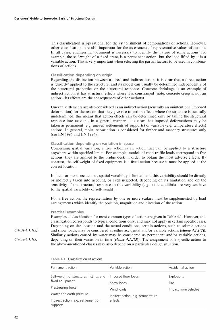
Clause 4.1.1(2)
Clause 4.1.1(3)
This classification is operational for the establishment of combinations of actions. However,other classifications are also important for the assessment of representative values of actions.In all cases, engineering judgement is necessary to identify the nature of some actions: forexample, the self-weight of a fixed crane is a permanent action, but the load lifted by it is avariable action. This is very important when selecting the partial factors to be used in combina-tions of actions.
Classification depending on originRegarding the distinction between a direct and indirect action, it is clear that a direct actionis ‘directly’ applied to the structure, and its model can usually be determined independently ofthe structural properties or the structural response. Concrete shrinkage is an example ofindirect action: it has structural effects where it is constrained (note: concrete creep is not anaction – its effects are the consequences of other actions).
Uneven settlements are also considered as an indirect action (generally an unintentional imposeddeformation) for the reason that they give rise to action effects where the structure is staticallyundetermined: this means that action effects can be determined only by taking the structuralresponse into account. In a general manner, it is clear that imposed deformations may betaken as permanent (e.g. uneven settlements of supports) or variable (e.g. temperature effects)actions. In general, moisture variation is considered for timber and masonry structures only(see EN 1995 and EN 1996).
Classification depending on variation in spaceConcerning spatial variation, a free action is an action that can be applied to a structureanywhere within specified limits. For example, models of road traffic loads correspond to freeactions: they are applied to the bridge deck in order to obtain the most adverse effects. Bycontrast, the self-weight of fixed equipment is a fixed action because it must be applied at thecorrect location.
In fact, for most free actions, spatial variability is limited, and this variability should be directlyor indirectly taken into account, or even neglected, depending on its limitation and on thesensitivity of the structural response to this variability (e.g. static equilibria are very sensitiveto the spatial variability of self-weight).
For a free action, the representation by one or more scalars must be supplemented by loadarrangements which identify the position, magnitude and direction of the action.
Practical examplesExamples of classification for most common types of action are given in Table 4.1. However, thisclassification corresponds to typical conditions only, and may not apply in certain specific cases.Depending on site location and the actual conditions, certain actions, such as seismic actionsand snow loads, may be considered as either accidental and/or variable actions (clause 4.1.1(2)).Similarly actions caused by water may be considered as permanent and/or variable actions,depending on their variation in time (clause 4.1.1(3)). The assignment of a specific action tothe above-mentioned classes may also depend on a particular design situation.
Designers’ Guide to Eurocode: Basis of Structural Design
Table 4.1. Classification of actions
Permanent action Variable action Accidental action
Self-weight of structures, fittings and
fixed equipment
Prestressing force
Water and earth pressure
Indirect action, e.g. settlement of
supports
Imposed floor loads
Snow loads
Wind loads
Indirect action, e.g. temperature
effects
Explosions
Fire
Impact from vehicles
42

In the case of seismic actions, in some countries or regions of Europe, earthquakes are not rareevents, and they can be treated as variable actions. For example, in the particular case of railwaybridges, two levels of magnitude may be defined: a moderate level, corresponding to a rathershort return period (e.g. 50 years – see the concept of the return period in Section 4.1.2),where the tracks supported by the bridge deck must not be damaged, and a higher level (e.g.corresponding to a 475 year return period – see later), where the tracks may be damaged butthe bridge structure remains usable (with more or less repair needed). Another example can befound in EN 1991-1-3, ‘Snow loads’: this Eurocode allows the treatment of snow loads asaccidental actions in some cases – in specific climatic regions where local drifting of snow onroofs is considered to form exceptional snow loads because of the rarity with which theyoccur, and are treated as accidental loads in accordance with EN 1990.
The prestressing force P is normally considered as a permanent action (see Section 4.1.2); moredetailed information on this is provided in thematerial Eurocodes EN 1992, EN 1993 and EN1994.
As mentioned above, the complete action model describes several properties of the action, such asits magnitude, position, direction and duration. In most cases, the magnitude of an action isdescribed by one quantity. For some actions a more complex representation of magnitudesmay be necessary, such as for multidimensional actions, dynamic actions and variable actionscausing fatigue of structural materials (clause 4.1(7)). For example, in the case of fatigueanalysis, it is necessary to identify a complete history of stress fluctuations, often in statisticalterms, or to describe a set of stress cycles and the corresponding number of cycles.
Classification depending on the nature and/or the structural responseConsidering the nature of actions and the structural response, all actions are classified as either(clause 4.1.1(4)P):
g static actions, which do not cause significant acceleration of the structure or structuralmember, or
g dynamic actions, which cause significant acceleration of the structure or structural member.
Often, the dynamic effects of actions are considered as quasi-static actions by increasing themagnitude of the static actions or by the introduction of an equivalent static action. Somevariable actions, static or dynamic, may cause stress fluctuations, which may lead to fatigue ofstructural materials.
In most cases, an action is represented by a single scalar, which may have several representativevalues (clause 4.1.1(5)). An example is the self-weight of a material with great variability (thecoefficient of variation within the range 0.05–0.1, depending on the type of structure, see thenote to clause 4.1.2(3)P) that has both favourable and unfavourable load effects. Then, twocharacteristic values, lower and upper, may be needed in the design calculation (see alsoclause 4.1.2(2)P).
In addition to the above classification of actions, EN 1990 considers the environmental influencesof chemical, physical and biological characteristics as a separate group of actions (clause 4.1.7).These influences have many aspects in common with mechanical actions; in particular, they maybe classified according to their variation in time as permanent (e.g. chemical impacts), variable(e.g. temperature and humidity influences) and accidental (e.g. spread of aggressive chemicals).Generally, environmental influences may cause time-dependent deterioration of materialproperties, and may therefore cause a gradual decrease of structural reliability.
4.1.2 Characteristic values of actionsGeneralAll actions, including environmental influences, are introduced in design calculations as variousrepresentative values. The most important representative value of an action F (clause 4.1.2(1)P) isthe characteristic value Fk. Depending on the available data and experience, the characteristicvalue should be specified in the relevant EN standard as a mean, an upper or lower value or anominal value (which does not refer to any statistical distribution). (In all Eurocodes, thewording ‘nominal value’ designates a value which is given in a design code, or in a regulation,
Clause 4.1(7)
Clause 4.1.1(4)P
Clause 4.1.1(5)
Clause 4.1.2(3)P
Clause 4.1.2(2)P
Clause 4.1.7
Clause 4.1.2(1)P
Chapter 4. Basic variables
43

Clause 4.1.2(1)P
Clause 4.1.2(1)P
Clause 4.1.2(2)P
Clause 4.1.2(2)P
Clause 4.1.2(3)P
Clause 4.1.2(3)
Clause 4.1.2(6)
Clause 4.1.2(5)
Clause 4.1.2(2)P
Clause 4.1.2(4)
or even in the design specification for a particular project, because it has not been possible toassess a characteristic value.) Exceptionally, the characteristic value of an action can also bespecified in the design or by the relevant competent authority, provided that the general provi-sions specified in EN 1990 are observed (clause 4.1.2(1)P).
There is a considerable lack of relevant statistical data concerning various actions and environ-mental influences. Consequently, the determination of a representative value of an action mayinvolve not only the evaluation and analysis of available observations and experimental data,but often, when there is a complete lack of sufficient statistical data, also a fairly subjectiveassessment, judgement (e.g. for particular accidental actions) or decision (e.g. for loads permittedon existing structures). For these cases, when the statistical distribution is not known, thecharacteristic value will be specified as a nominal value (clause 4.1.2(1)P). Nevertheless, all thecharacteristic values, regardless of the methods used for their original determination, aretreated in EN 1990 in the same way.
Permanent actionsWith regard to determining the permanent actions G (clause 4.1.2(2)P), particularly for the deter-mination of self-weight for traditional structural materials, sufficient statistical data may beavailable. If the variability of a permanent action is small, a single characteristic value Gk maybe used. Then, Gk should be taken as the mean (clause 4.1.2(2)P).
When the variability of a permanent action is not small, two values have to be used: an uppervalue Gk,sup and a lower value Gk,inf (clause 4.1.2(3)P).
For example, in the case of bridges:
g the self-weight of the bridge deck (for the assessment of the bending moment, shear force,torsion moment, etc.) is taken into account using its mean value because its variability issmall (the execution of a bridge is generally strictly controlled by competent personnel)
g the self-weight of items such as vehicle parapets, waterproofing, coatings and railwayballast is taken into account using an upper and a lower characteristic value because thevariability (even in time) may not be small (see EN 1991-1-1).
The variability of permanent actions can usually be assumed to be small if the coefficient ofvariation during the design life is not greater than 0.05–0.1 (the recommended value inclause 4.1.2(3)), depending on the type of structure. In fact, this range of values is intended toaccount for the effects of self-weight in common buildings. In the case of bridges, and in parti-cular for long-span bridges, the variability of the effects of self-weight may be in a smallerrange, for example, between 0.02 and 0.05.
However, if the structure is very sensitive to variations in G (e.g. some types of prestressedconcrete structures), two values have to be considered, even if the coefficient of variation issmall (clause 4.1.2(6)).
In the case of self-weight, a single value may be used, andGk can be assumed to be the mean value�G (Figure 4.1; definitions of basic statistical parameters are given in Appendix 3 of this guide),calculated on the basis of nominal dimensions and mean unit mass (clause 4.1.2(5)), using valuesprovided in EN 1991-1-1, ‘Densities, self weight and imposed loads for buildings’. In other cases,when two values are to be used (clauses 4.1.2(2)P and 4.1.2(4)), a lower value Gk,inf and an uppervalue Gk,sup, representing the 0.05 or 0.95 fractiles, respectively, should be used, as shown inFigure 4.1. The normal (Gaussian) distribution may be generally assumed for self-weight.
Assuming a normal distribution, the following relationships (see Appendix 2 of this chapter fordefinitions of statistical terms and the basic statistical techniques involved) can be used todetermine the lower value Gk,inf and the upper value Gk,sup:
Gk,inf¼�G� 1.64�G¼�G(1� 1.64VG) (D4.1)
Gk,sup¼�Gþ 1.64�G¼�G(1þ 1.64VG) (D4.2)
Designers’ Guide to Eurocode: Basis of Structural Design
44

where VG denotes the coefficient of variation of G. It follows from the above equations (see alsoFigure 4.1) that, for a coefficient of variation of 0.10 (which is a hypothetical boundary betweenlow and high variability of permanent actions), Gk,inf and Gk,sup will therefore be 16.4% less thanor greater than the mean value �G.
There may be special cases of particular design situations (e.g. when considering overturning andstrength of retaining walls) when both the lower value Gk,inf and the upper value Gk,sup should beused in the design (see also Chapter 6).
A special type of loading is represented by prestressing (P), which should be, as indicated inTable 4.1, considered as a permanent action (clause 4.1.2(6)). The permanent action due to Pmay be caused either by controlled forces (e.g. prestressing by tendons) or controlled deforma-tions (e.g. prestressing by an imposed deformation at a support). Physically, however, P is atime-dependent action (monotonous), and its characteristic values may, therefore, depend ontime (see the note to clause 4.1.2(6)). It has to be noted that, in accordance with EN 1991-1-6,‘Actions during execution’, jack forces activated during the prestressing should be classified asvariable actions for the anchor region.
Variable actionsThe volume of available statistical data for the most common variable actions allows anassessment of their characteristic value Qk by a probabilistic approach. In some cases, asstated in clause 4.1.1(7)P, the characteristic value may be a nominal value.
For example, in most European countries, climatic data are available over more than the past40 years, and allow a scientific determination of actions due to wind, snow and temperature.For the calibration of traffic loads on road bridges (EN 1991-2), traffic records representingmore than 200 000 heavy vehicles on a main European motorway were used. The situationregarding imposed loads on floor buildings or dynamic actions due to pedestrians on a footbridgeis less satisfactory, but Eurocode 1 gives the right orders of magnitude.
When a statistical treatment is possible, the characteristic value Qk corresponds either to anupper value with an intended probability of it not being exceeded (the most common case), orto a lower value with an intended probability of not falling below it, during an assumed referenceperiod. Hence, two separate elements are used to define the characteristic value: the referenceperiod during which the extreme (maximum or minimum) is observed, and the intendedprobability with which these extreme values should not exceed or should not fall below thecharacteristic value. In general, the characteristic value Qk of climatic actions and imposedloads on building floors for persistent design situations is based on an intended probability
Clause 4.1.2(6)
Clause 4.1.2(6)
Clause 4.1.1(7)P
Chapter 4. Basic variables
Figure 4.1. Definition of lower (Gk,inf) and upper (Gk,sup) characteristic values of permanent actions
based on a normal distribution
Probability density
1.65σG
σG σG
µG Gk,supGGk,inf
1.65σG
45

Clause 4.1.2(7)
Clause 4.1.2(7)
Clause 4.1.2(8)
Clause 4.1.2(9)
of the value not being exceeded of 0.98, and a reference period of 1 year (see note 2 ofclause 4.1.2(7)).
BackgroundThe concept of reference period is illustrated in Figure 4.2, which shows variable action Qversus time t. The reference period � is indicated as a certain time period (e.g. 1 year) onthe abscissa axis. During each reference period � the variable action Q reaches itsmaximum value Qmax (e.g. the annual extreme). In this way, a sequence of values Q1,max,Q2,max, Q3,max, . . . can be obtained. The distribution of these values of Qmax (e.g. thedistribution of annual extremes) is indicated in Figure 4.2 by a probability density function’Qmax(Q), where Q denotes a generic value of Q here. The characteristic value Qk
(Figure 4.2) can then be defined by the requirement that it will be exceeded by Qmax (e.g.annual extremes) only with a limited probability p, say 0.02. Thus, the characteristic valueQk is p-fractile of the extremes values Qmax (‘fractile’ is defined in Appendix C of this guide).
Figure 4.2. Variable action Q as a function of time t and the characteristic value Qk
Probability density
ϕQmax(Q)
ττττ
Qi,max
Q3,max
Q2,max
Q1,max
t
Qik
p
The probability p of the characteristic value not being exceeded and the reference period � arelinked by the equation
T ¼ �
p
where T is the return period (expected period between two subsequent occurrences of thecharacteristic value being exceeded) of the value corresponding to probability p. Thus, for aprobability p¼ 0.02 and a reference period of 1 year, the return period of the characteristicvalue is T¼ 1/0.02¼ 50 years. According to note 2 of clause 4.1.2(7), depending on the characterof the variable action, a different reference period may be more appropriate, and this will changethe intended probability of the characteristic value not being exceeded and the return period.
Note that some variable actions may not have a periodical character similar to climatic or trafficactions and the above concepts of reference period and return period may not be suitable. In thiscase the characteristic value of a variable action may be determined in a different way, taking intoaccount its actual nature. For example, variable actions caused by water should generally becalculated by allowing for fluctuating water levels and for variation in appropriate geometricparameters, such as the profile of the structure or of components exposed to water.
Accidental actionsLess statistical information is available for accidental actions than for permanent and variableactions. The appropriate clauses (clauses 4.1.2(8) to 4.1.2(9)) may be very simply summarised
Designers’ Guide to Eurocode: Basis of Structural Design
46
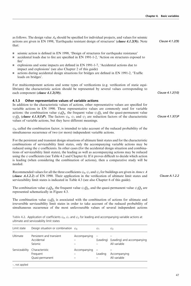
as follows. The design value Ad should be specified for individual projects, and values for seismicactions are given in EN 1998, ‘Earthquake resistant design of structures’ (clause 4.1.2(9)). Notethat:
g seismic action is defined in EN 1998, ‘Design of structures for earthquake resistance’g accidental loads due to fire are specified in EN 1991-1-2, ‘Action on structures exposed to
fire’g explosions and some impacts are defined in EN 1991-1-7, ‘Accidental actions due to
impact and explosions’ (see also Chapter 2 of this guide)g actions during accidental design situations for bridges are defined in EN 1991-2, ‘Traffic
loads on bridges’.
For multicomponent actions and some types of verifications (e.g. verification of static equi-librium) the characteristic action should be represented by several values corresponding toeach component (clause 4.1.2(10)).
4.1.3 Other representative values of variable actionsIn addition to the characteristic values of actions, other representative values are specified forvariable actions in EN 1990. Three representative values are commonly used for variableactions: the combination value 0Qk, the frequent value 1Qk and the quasi-permanent value 2Qk (clause 4.1.3(1)P). The factors 0, 1 and 2 are reduction factors of the characteristicvalues of variable actions, but they have different meanings.
0, called the combination factor, is intended to take account of the reduced probability of thesimultaneous occurrence of two (or more) independent variable actions.
For the persistent and transient design situations of ultimate limit states and for the characteristiccombinations of serviceability limit states, only the accompanying variable actions may bereduced using the coefficients. In other cases (for the accidental design situation and combina-tions of serviceability limit states), the leading as well as accompanying actions may be reducedusing the coefficients (see Table 4.2 and Chapter 6). If it proves difficult to decide which actionis leading (when considering the combination of actions), then a comparative study will beneeded.
Recommended values for all the three coefficients 0, 1 and 2 for buildings are given inAnnex A(clause A.1.2.2) of EN 1990. Their application in the verification of ultimate limit states andserviceability limit states is indicated in Table 4.3 (see also Chapter 6 of this guide).
The combination value 0Qk, the frequent value 1Qk, and the quasi-permanent value 2Qk arerepresented schematically in Figure 4.3.
The combination value 0Qk is associated with the combination of actions for ultimate andirreversible serviceability limit states in order to take account of the reduced probability ofsimultaneous occurrence of the most unfavourable values of several independent actions
Clause 4.1.2(9)
Clause 4.1.2(10)
Clause 4.1.3(1)P
Clause A.1.2.2
Chapter 4. Basic variables
Table 4.2. Application of coefficients 0, 1 and 2 for leading and accompanying variable actions at
ultimate and serviceability limit states
Limit state Design situation or combination 0 1 2
Ultimate Persistent and transient Accompanying – –
Accidental – (Leading) (Leading) and accompanying
Seismic – – All variable
Serviceability Characteristic Accompanying – –
Frequent – Leading Accompanying
Quasi-permanent – – All variable
–, not applied
47

Clause 4.1.3(1)P
Clause 4.1.3(1)P
Clause 4.1.3(1)P
(clause 4.1.3(1)P). The statistical technique used to determine 0 is presented in Annex C ofEN 1990 (see also Chapter 9 of this guide). The coefficient 0 for combination values of someimposed actions in buildings is typically equal to 0.7 (see Annex A1 of EN 1990 and Chapter 7of this guide); this value is approximately indicated in Figure 4.3.
The frequent value 1Qk is primarily associated with the frequent combination in the service-ability limit states, and it is also assumed to be appropriate for the verification of the accidentaldesign situation of the ultimate limit states. In both cases, the reduction factor 1 is applied as amultiplier of the leading variable action. In accordance with EN 1990, the frequent value 1Qk ofa variable action Q is determined so that the total time, within a chosen period of time, duringwhich Q> 1Qk is only a specified (small) part of the period, or the frequency of the eventQ> 1Qk is limited to a given value. The total time for which 1Qk is exceeded is equal to thesum of time periods �t1, �t2, . . . shown in Figure 4.3 by thick parts of the horizontal lineindicating the frequent value 1Qk.
According to note 1 of clause 4.1.3(1)P, the value of 0.01 for the reference period (50 yearsfor buildings) is recommended. Specific conditions apply for traffic load on bridges (clause4.1.3(1)P, notes 1 and 2). A detailed description is provided in EN 1991-2 for traffic loads, inEN 1991-1-5 for thermal actions and in 1991-1-4 for wind; no further comment is made in thisguide.
Designers’ Guide to Eurocode: Basis of Structural Design
Table 4.3. The coefficient kP,� for the determination of the lower 5% and 0.1% fractiles, assuming a three-
parameter log-normal distribution
Coefficient of skewness �X Coefficient kP,� for P¼ 5% Coefficient kP,� for P¼ 0.1%
�2.0 �1.89 �6.24
�1.0 �1.85 �4.70
�0.5 �1.77 �3.86
0.0 �1.64 �3.09
0.5 �1.49 �2.46
1.0 �1.34 �1.99
2.0 �1.10 �1.42
Figure 4.3. Representative values of variable actions
Instantaneous value of Q
Characteristic value of Qk
Combination value ψ0Qk
Frequent value ψ1Qk
Quasi-permanentvalue ψ2Qk
∆t1 ∆t2 ∆t3
Time
48

The coefficient 1 for the frequent value of some imposed actions in buildings, and actions in carparks, is equal to 0.5 (see Annex A1 of EN 1990 and Chapter 7 of this guide); this value is alsoindicated approximately in Figure 4.3.
Note that the recommended values may be altered, depending on the type of construction worksand design situations considered in the design. In some cases, two (upper and lower) or morefrequent values may be used.
The main use of quasi-permanent values 2Qk is the assessment of long-term effects (e.g. creepeffects in continuous prestressed concrete bridges). However, they are also used for the represen-tation of variable actions in accidental and seismic combinations of actions (ultimate limit states)and for the verification of frequent and quasi-permanent combinations (long-term effects) ofserviceability limit states (clause 4.1.3(1)P).
In accordance with EN 1990, the quasi-permanent value 2Qk is defined so that the total time,within a chosen period of time, during which it is exceeded, that is, whenQ> 2Qk, is a consider-able part (0.5) of the chosen period of time (clause 4.1.3(1)P, note in point (c)). The value mayalso be determined as the value averaged over the chosen period of time. For some actions thecoefficient 2 may be very small. For example, in the case of traffic loads on road bridges, thequasi-permanent value is taken equal to 0 (except for heavily loaded bridges in urban areas,especially in seismic design situations).
The total time of 2Qk being exceeded is equal to the sum of periods, shown in Figure 4.3 by thickparts of the horizontal line indicating the quasi-permanent value 2Qk. In some cases thecoefficient 2 for the frequent value of imposed actions is equal to 0.3 (see Annex A1 ofEN 1990 and Chapter 7 of this guide); this value is indicated approximately in Figure 4.3.
The representative values 0Qk, 1Qk and 2Qk and the characteristic values are used to definethe design values of the actions and the combinations of actions, as explained in Chapter 6. Theirapplication in verification of the ultimate limit states and serviceability limit states is indicated inTable 4.2. Representative values other than those described above may be required for specificstructures and special types of load (e.g. fatigue load (clause 4.1.4)).
4.1.4 Representation of fatigue actionsIt is well recognised that the fluctuation of loads may cause fatigue. The models for fatigueactions should be taken from appropriate parts of EN 1991 relevant for the structure considered(clause 4.1.4(1)). When no information is available in EN 1991, then the evaluation of measure-ments of the expected action spectra should be used (clause 4.1.4(2)). When evaluating the effectsof fluctuating loads, the material Eurocodes EN 1992 to EN 1999 should be used to obtain therequired information and, therefore, no further comment is offered in this guide.
4.1.5 Representation of dynamic actionsThe effects of acceleration due to time-dependent actions are generally included in the character-istic fatigue models provided in EN 1991 either implicitly in the characteristic load or explicitlyusing the dynamic enhancement factors (clause 4.1.5(1)). However, time-dependent actions maycause significant effects, and then a dynamic analysis of the whole structural system should beused (clause 4.1.5(2)). General guidance concerning structural analysis is provided inclause 5.1.3 of EN 1990 and in Chapter 5 of this guide.
4.1.6 Geotechnical actionsNo specific information on geotechnical actions is provided in EN 1990. Guidance ongeotechnical actions is found in EN 1997, however, and is thus outside the scope of this guide.
4.1.7 Environmental influencesEnvironmental influences (carbon dioxide, chlorides, humidity, fire, etc.) may affect thematerial properties markedly, and consequently affect the safety and serviceability of structuresin an unfavourable way. These effects are strongly material-dependent, and therefore theircharacteristics have to be specified individually for each material in EN 1992 to EN 1999(clause 4.1.7(1)P).
Clause 4.1.3(1)P
Clause 4.1.3(1)P
Clause 4.1.4
Clause 4.1.4(1)
Clause 4.1.4(2)
Clause 4.1.5(1)
Clause 4.1.5(2)
Clause 5.1.3
Clause 4.1.7(1)P
Chapter 4. Basic variables
49
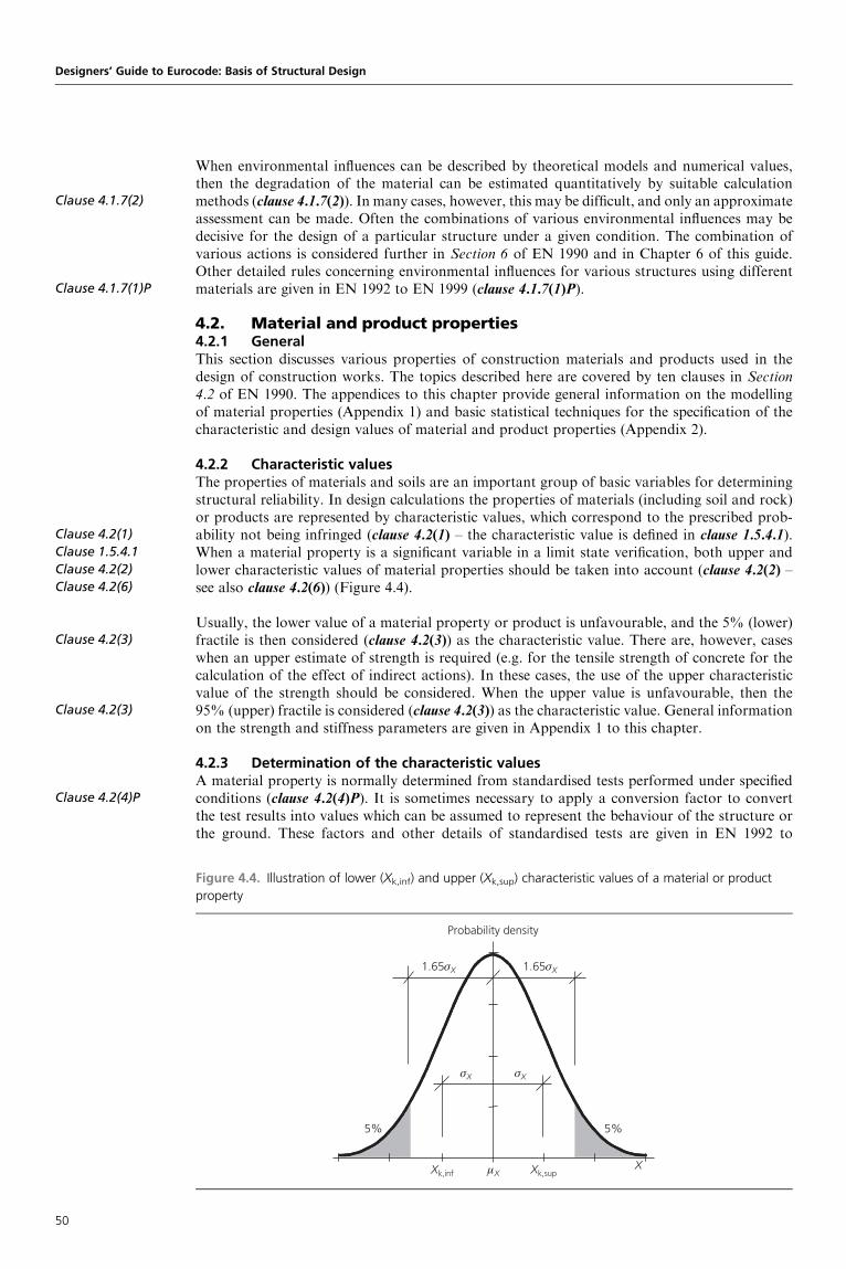
Clause 4.1.7(2)
Clause 4.1.7(1)P
Clause 4.2(1)
Clause 1.5.4.1
Clause 4.2(2)
Clause 4.2(6)
Clause 4.2(3)
Clause 4.2(3)
Clause 4.2(4)P
When environmental influences can be described by theoretical models and numerical values,then the degradation of the material can be estimated quantitatively by suitable calculationmethods (clause 4.1.7(2)). In many cases, however, this may be difficult, and only an approximateassessment can be made. Often the combinations of various environmental influences may bedecisive for the design of a particular structure under a given condition. The combination ofvarious actions is considered further in Section 6 of EN 1990 and in Chapter 6 of this guide.Other detailed rules concerning environmental influences for various structures using differentmaterials are given in EN 1992 to EN 1999 (clause 4.1.7(1)P).
4.2. Material and product properties4.2.1 GeneralThis section discusses various properties of construction materials and products used in thedesign of construction works. The topics described here are covered by ten clauses in Section4.2 of EN 1990. The appendices to this chapter provide general information on the modellingof material properties (Appendix 1) and basic statistical techniques for the specification of thecharacteristic and design values of material and product properties (Appendix 2).
4.2.2 Characteristic valuesThe properties of materials and soils are an important group of basic variables for determiningstructural reliability. In design calculations the properties of materials (including soil and rock)or products are represented by characteristic values, which correspond to the prescribed prob-ability not being infringed (clause 4.2(1) – the characteristic value is defined in clause 1.5.4.1).When a material property is a significant variable in a limit state verification, both upper andlower characteristic values of material properties should be taken into account (clause 4.2(2) –see also clause 4.2(6)) (Figure 4.4).
Usually, the lower value of a material property or product is unfavourable, and the 5% (lower)fractile is then considered (clause 4.2(3)) as the characteristic value. There are, however, caseswhen an upper estimate of strength is required (e.g. for the tensile strength of concrete for thecalculation of the effect of indirect actions). In these cases, the use of the upper characteristicvalue of the strength should be considered. When the upper value is unfavourable, then the95% (upper) fractile is considered (clause 4.2(3)) as the characteristic value. General informationon the strength and stiffness parameters are given in Appendix 1 to this chapter.
4.2.3 Determination of the characteristic valuesA material property is normally determined from standardised tests performed under specifiedconditions (clause 4.2(4)P). It is sometimes necessary to apply a conversion factor to convertthe test results into values which can be assumed to represent the behaviour of the structure orthe ground. These factors and other details of standardised tests are given in EN 1992 to
Designers’ Guide to Eurocode: Basis of Structural Design
Figure 4.4. Illustration of lower (Xk,inf) and upper (Xk,sup) characteristic values of a material or product
property
Probability density
1.65σX
σX σX
µX Xk,supXXk,inf
1.65σX
5% 5%
50

EN 1999. For traditional materials (e.g. steel and concrete), previous experience and extensivetests are available, and appropriate conversion factors are well established and presented invarious design codes (see Chapters 6 and 10 of this guide). The properties of new materialsshould be obtained from an extensive testing programme, including tests on complete structures,revealing the relevant properties and appropriate conversion factors. New materials should beintroduced only if comprehensive information on their properties (supported by experimentalevidence) is available.
Assuming that the theoretical model for the random behaviour of a material property is known,or sufficient data are available to determine such a model, basic operational rules to obtainspecified fractiles are described in Appendix 2 of this chapter. If only limited test data areavailable, then statistical uncertainty owing to limited data should be taken into account, andthe above-mentioned operational rules should be substituted by more complicated statisticaltechniques (see Annex D of EN 1990 and also Chapter 10 and Appendix C of this guide).
According to clause 4.2(5), whenever there is a lack of information on the statistical distributionof a property, a nominal value may be used in the design. In the case of insignificant sensitivityto the variability of a property, a mean value may be considered as the characteristic value.Relevant values for material properties and their definitions are available in EN 1992 toEN 1999 (clause 4.2(7)P).
Note that stiffness parameters are normally defined as mean values (clause 4.2(8)). This can beexplained in the following way. Very often, stiffness parameters are used in interaction models(e.g. ground–structure interaction) or in finite-element models associating several materials.The stiffness properties of materials cannot be altered by partial factors because the results ofthe calculation would be distorted. It is for this reason that it is recommended that stiffnessparameters are not altered. Nevertheless, in some cases (e.g. for the calculation of piles subjectto horizontal forces at the top), it may be necessary to take into account a lower and an uppervalue of these parameters, generally assessed from engineering judgement.
In general, when the lower or upper characteristic value is derived from tests, the available datashould be carefully examined for cases where a material (e.g. timber or steel) is classified using agrading system comprising a number of classes to account for the possibility that the manufac-turer may have included specimens that fail in the upper grade in the lower grade, thus distortingthe statistical characteristics (including the mean, standard deviation and fractiles) of the lowergrade (Figure 4.5). Obviously, such a ‘mixture’ of two grades may significantly affect both thelower and upper characteristic values.
Specific values for material and product properties are given in the material-oriented EurocodesEN 1992 to EN 1999 (clause 4.2(9)), where appropriate partial factors are also specified (clause4.2(10)). Unless suitable statistical information exists, a conservative value of partial factorsshould be used (clause 4.2(10)).
Clause 4.2(5)
Clause 4.2(7)P
Clause 4.2(8)
Clause 4.2(9)
Clause 4.2(10)
Clause 4.2(10)
Chapter 4. Basic variables
Figure 4.5. Distortion of a statistical distribution due to the combination of two material grades
Probability density of X
Upper grade
Lower grade
X
51

Clause 4.3(1)P
Clause 4.3(2)
Clause 4.3(3)
Clause 4.3(4)
Clause 4.3(5)P
Clause 4.3(1)P
Clause 4.3(2)
Clause 4.3(3)
Clause 4.3(3)
Clause 4.3(5)P
4.3. Geometrical dataThis section is concerned with the geometrical data used in the design of building structuresand civil engineering works. The material described here is covered in five clauses in EN 1990(clauses 4.3(1)P, 4.3(2), 4.3(3), 4.3(4) and 4.3(5)P. The appendices to this chapter provideinformation on the characteristics of geometrical quantities (see Appendix 3) and tolerancesfor overall imperfections (see Appendix 4).
Geometrical variables describe the shape, size and the overall arrangement of structures,structural members and cross-sections. In the design, account should be taken of the possiblevariation of their magnitudes, which depend on the level of workmanship in the manufactureand execution processes (setting out, execution, etc.) on the site. In design calculations thegeometrical data should be represented by their characteristic values or, in the case of imperfec-tions, directly by their design values (clause 4.3(1)P). According to clause 4.3(2) the characteristicvalues usually correspond to the dimensions specified in the design, which are the nominal values(see Figure 4.5). However, where relevant, the values of geometrical quantities may correspond tosome prescribed fractile of the available statistical distribution (clause 4.3(3)). This value may bedetermined using Equation (D4.14) in Appendix 3 to this chapter.
An important category of geometrical data that may have significant effect on structuralreliability and should therefore be taken into account in the design consists of various types ofimperfection (clause 4.3(3)). Depending on the material and type of structure, imperfectionsare specified in the material-oriented EN 1992 to EN 1999.
According to the important principle of clause 4.3(5)P, tolerances for connected parts should bemutually compatible. To verify the mutual compatibility of all the specified tolerances, a separateanalysis taking into account the imperfections and the deviations provided in other standards(EN 1992 to EN 1999) may be necessary. Such an analysis is particularly important, for example,for the case when large-span precast components are used as structural elements or infill internal orexternal (cladding) components. Statistical methods described in BS 5606 give a detailed descriptionof methods which may be applied to verify the mutual compatibility of all the considered tolerances.
Note that the permitted deviations for various geometric data describing concrete componentsare specified in ENV 13670-1, ‘Execution of concrete structures – Part 1: Common’.
Appendix 1: modelling of material propertiesGeneral notesThe material properties used in structural analysis and design should be described by measurablephysical quantities corresponding to the properties considered in the calculation models. As arule, these physical quantities are time-dependent, and may additionally be dependent upontemperature, humidity, load history and environmental influences. They also depend on specifiedconditions concerning the manufacturing, supply and acceptance criteria.
Material properties and their variation should generally be determined from tests using standard-ised test specimens. The tests should be based on random samples which are representative of thepopulation under consideration. To determine the properties corresponding to the assumptionsmade in calculation models, the properties obtained from test specimens often require convertingusing appropriately defined conversion factors or functions. The uncertainties of the conversionfactors should also be considered in calculation models. Conversion factors usually cover sizeeffects, shape effects, time effects and the effects of temperature, humidity and other environ-mental influences.
For soils, as for existing structures, the materials are not produced but are found in situ. There-fore, the values of the properties have to be determined for each project using appropriate tests. Adetailed investigation based on test results may then provide more precise and complete infor-mation than would pure statistical data, especially with respect to systematic trends or weakspots in the spatial distributions. However, fluctuations in homogeneous materials and thelimited precision of the tests and their physical interpretations can be treated by statisticalmethods. For these materials the extent of investigation is an important element of theirstructural reliability, which is often difficult to quantify.
Designers’ Guide to Eurocode: Basis of Structural Design
52

At the design stage, assumptions need to be made concerning the intended materials for theconstruction works. Therefore, corresponding statistical parameters have to be deduced fromprevious experience and existing populations which are considered appropriate to the construc-tion works. The chosen parameters should be checked at the execution stage for quality usingsuitable (preferably statistical) methods of quality control. The identification of sufficientlyhomogeneous populations (e.g. appropriate divisions of the production in batches) and thesize of samples are then other important aspects to specify appropriate elements of structuralreliability.
Important material propertiesThe most important material properties introduced in design calculations describe the funda-mental engineering aspects of building materials:
g strength fg modulus of elasticity Eg yield stress (if applicable) �yg limit of proportionality "yg strain at rupture "f.
Figure 4.6 shows a typical example of a one-dimensional stress (�)–strain (") diagram, togetherwith the above-mentioned fundamental quantities.
In design calculations, strength parameters are usually introduced by the lower 5% fractilesrepresenting the characteristic values; stiffness parameters are introduced by their mean values(see Section 4.2). However, when stiffness affects the structural load-bearing capacity, anappropriate choice of the relevant partial factor should compensate for the mean value choice.As mentioned in Section 4.2, in some cases, the upper characteristic value for the strength isof importance (e.g. for the tensile strength of concrete when the effect of indirect action is calcu-lated). Some of the above-mentioned properties (e.g. strain at rupture) may be introduced indesign calculations implicitly by appropriate conditions for the validity of theoretical modelsof cross-section or structural member behaviour.
In addition to the basic material properties in the one-dimensional stress (�)–strain (") diagramabove (see Figure 4.6), other important aspects need to be considered:
g multi-axial stress condition (e.g. the Poisson ratio, yield surface, flow and hardening rules,crack creation and crack behaviour)
g temperature effects (e.g. coefficient of expansion, and effect on material propertiesincluding extreme conditions)
Chapter 4. Basic variables
Figure 4.6. One-dimensional �–" diagram
σ
ε
f
σy
εy εf
53

g time effect (e.g. effect of internal and external influences, creep, creep rupture,consolidation of soils, and fatigue deterioration)
g dynamic effects (e.g. mass density and material damping, and effect of loading rate)g humidity effects (e.g. shrinkage, effect on strength, stiffness and ductility)g effects of notches and flaws (e.g. unstable check growth, brittle fracture, stress intensity
factor, effect of ductility and crack geometry, and toughness).
Fatigue behaviourA very significant material property is the fatigue behaviour of structural members. This time-dependent effect of repeated loading of structural members is generally investigated by simplifiedtests, where the members are subjected to load variations of constant amplitude until excessivedeformations or fracture due to cracks occur. The fatigue strength is then defined by character-istic ��–N curves that represent the 5% fractiles of failure. The test evaluation is carried out inaccordance with Annex D of EN 1990 and the appropriate provisions of EN 1992 to EN 1999.
The characteristic ��–N curves are normally represented in a double logarithmic scale, asindicated in Figure 4.7. The corresponding equation has the form
��mN¼C¼ constant (D4.3)
where �� represents the stress range calculated from the load range using appropriate materialand geometrical properties taking into account stress concentration factors, and N correspondsto the number of cycles. In some cases, the stress concentration factors are introduced as anexplicit coefficient of the nominal stress range.
Generally, the ��–N curves are dependent on geometric stress concentration and metallurgicalaspects. Further details on the characteristic��–N curves for different materials can be found inEN 1992 to EN 1999.
Appendix 2: basic statistical techniques for determination of thecharacteristic valueNormal and three-parameter log-normal distributionsAs most material properties are random variables of considerable scatter, applied characteristicvalues should always be based on appropriate statistical parameters or fractiles. Commonly, for agiven material property X the following statistical parameters are considered: the mean �X,standard deviation �X, coefficient of skewness (asymmetry) �X or other statistical parameters,for example, the lower or upper distribution limit. In the case of a symmetrical distribution
Designers’ Guide to Eurocode: Basis of Structural Design
Figure 4.7. The characteristic ��–N curve
log ∆σ
log N
m
1
54

(e.g. the normal distribution) the coefficient �X¼ 0, and only the mean �X and standard deviation�X are considered. This type of distribution is indicated in Figure 4.8 by the solid curve.
The characteristic and design values of material properties are defined as specified fractiles of theappropriate distribution. Usually the lower 5% fractile is considered for the characteristicstrength, and a smaller fractile probability (around 0.1%) is considered for the design value. Ifthe normal distribution is assumed, the characteristic value Xk, defined as the 5% lowerfractile, is derived from the statistical parameters �X and �X as
Xk¼�X� 1.64�X (D4.4)
where the coefficient�1.64 corresponds to the fractile probability 5%. The statistical parameters�X, �X and the characteristic value Xk are shown in Figure 4.8 together with the normal prob-ability density function of the variable X (solid curve). The coefficient �3.09 should be usedwhen the 0.1% lower fractile (design value) is considered.
Generally, however, the probability distribution of the material property X may have anasymmetrical distribution with positive or negative skewness �X. The dashed curve inFigure 4.8 shows the general three-parameter (one-sided) log-normal distribution having apositive coefficient of skewness �X¼ 1 and therefore the upper limit X0¼�xþ 3.10�x.
In the case of an asymmetric distribution a fractile Xp corresponding to the probability P maythen be calculated from the general relationship
Xp¼�Xþ kP,��X (D4.5)
where the coefficient kP,� depends on the probability P and on the coefficient of skewness �X.Assuming the three-parameter log-normal distribution, selected values of the coefficient kP,�for determination of the lower 5% and 0.1% fractiles are given in Table 4.3.
It follows from Table 4.3 and Equation (D4.5) that the lower 5% and 0.1% fractiles for thenormal distribution (when �X¼ 0) may be considerably different from those corresponding toan asymmetrical log-normal distribution. When the coefficient of skewness is negative, �X< 0,the predicted lower fractiles for the log-normal distribution are less (unfavourable) than thoseobtained from the normal distribution with the same mean and standard deviation. When thecoefficient of skewness is positive, �X> 0 (see Figure 4.8), the predicted lower fractiles for
Chapter 4. Basic variables
Figure 4.8. Characteristics of a material property
Probability density of X
5%
1.64σX
αX = 0σX σX
µXXXk X ′k
55

the log-normal distribution are greater (favourable) than those obtained from the normaldistribution.
Log-normal distribution with the lower bound at zeroA popular log-normal distribution with the lower bound at zero, which is used frequently forvarious material properties, always has a positive skewness �X> 0 given as
�X¼ 3wXþ w3X (D4.6)
where wX denotes the coefficient of variation of X. When, for example, wX¼ 0.15 (a typical valuefor in-situ cast concrete), then �Xffi 0.45. For this special type of distribution the coefficients kP,�can be obtained from Table 4.3, taking into account skewness �X given by Equation (D.4.6).Alternatively, the fractile of the log-normal distribution with the lower bound at zero can bedetermined from the following equation:
XP¼�X exp[kP,0pln(1þ w2
X)]/p(1þ w2
X) (D4.7)
which is often simplified (for wX< 0.2) as
XP¼�X exp(kP,0wX) (D4.8)
Note that kP,0 is the coefficient taken from Table 4.3 for the skewness �x¼ 0 (as for the normaldistribution). Usually, the probability P¼ 0.05 is assumed for the characteristic value X0.05¼Xk,and the probability P¼ 0.001 is approximately considered for the design value X0.001ffiXd. Therelationship of these important fractiles determined from Equation (D4.8) with the mean �X canbe seen from the ratios X0.05/�X and X0.001/�X shown in Figure 4.9 as functions of the coefficientof variation wX. Figure 4.9 also shows the corresponding skewness �X given by Equation (D4.6).
The skewness �X indicated in Figure 4.9 should be used for verification of whether the assumedlog-normal distribution with the lower bound at zero is a suitable theoretical model. If the actualskewness determined from available data for a given wX is considerably different from thatindicated in Figure 4.9 (which is given by Equation (D4.6)), then a more general three-parameterlog-normal or other type of distribution should be used. In such a case, Equation (D4.5) andcoefficient kP,� taken from Table 4.3 may provide a good approximation. If the actual skewnessis small, say |�X|< 0.1, then the normal distribution may be used as a good approximation.
When the normal distribution is used and the actual distribution has a negative coefficient ofskewness, �X< 0, the predicted lower fractiles will then have an unfavourable error (i.e. willbe greater than the correct values). For the case when the correct distribution has a positivecoefficient of skewness, �X> 0, the predicted lower fractiles will have a favourable error (i.e.
Designers’ Guide to Eurocode: Basis of Structural Design
Figure 4.9. The skewness �x and fractiles X0.05 and X0.001 (the characteristic and design values) as
fractions of the mean �X for the log-normal distribution with the lower bound at zero versus the
coefficient of variation wX
00 0.05 0.10 0.15 0.20
0.2
0.4
0.6
0.8
1.0
wX
αX
X0.001/µX
X0.05/µX
56

will be less than the correct values). In the case of the 5% lower fractile value (commonlyaccepted for the characteristic value) with the coefficient of skewness within the intervalh�1, 1i the error created is about 6% for a coefficient of variation less than 0.2.
Considerably greater differences may occur for the 0.1% fractile value (which is approximate fordesign values) when the effect of asymmetry is significant. For example, in the case of a negativeasymmetry with �X¼�0.5 (indicated by statistical data for the strength of some grades of steeland concrete), and a coefficient of variation of 0.15 (suitable for concrete), the correct value of the0.1% fractile value corresponds to 78% of the value predicted assuming the normal distribution.When the coefficient of variation is 0.2, then the correct value decreases to almost 50% of thevalue determined assuming the normal distribution.
However, when the material property has a distribution with a positive skewness, then theestimated lower fractile values obtained from the normal distribution may be considerablylower (and therefore conservative and uneconomical) than the theoretically correct valuecorresponding to the appropriate asymmetrical distribution. Generally, consideration ofasymmetry to determine properties is recommended (see also Appendix B to this guide)whenever the coefficient of variation is greater than 0.1 or the coefficient of skewness isoutside the interval h�0.5, 0.5i. This is one of the reasons why the design value of a materialproperty should preferably be determined as a product of the characteristic value, which is notvery sensitive to asymmetry, and of the appropriate partial factor �m.
When the upper fractiles representing upper characteristic values are needed, Equation (D4.5)may be used provided that all numerical values for the coefficient of skewness �X and kP,�given in Table 4.3 are taken with the opposite sign. However, in this case the experimentaldata should be carefully checked to avoid the possible effect of material not passing thequality test for the higher grade (see Section 4.2 and Figures 4.3 and 4.4).
The above operational rules are applicable when the theoretical model for the probability distri-bution is known (e.g. from extensive experimental data or from previous experience). If, however,only limited experimental data are available, then a more complicated statistical techniqueshould be used (see Annex D of EN 1990) to take account of statistical uncertainty due tolimited information.
Chapter 4. Basic variables
Example 4.1Consider a concrete with mean �X¼ 30MPa and standard deviation �X¼ 5MPa (coefficientof variation wX¼ 0.167). Then, the 5% fractile (the characteristic value) is:
g assuming a normal distribution (Equation (D4.5)),
X0.05¼�X� kP,0�X¼ 30 �1.64� 5¼ 21.7MPa (D4.9)
g assuming a log-normal distribution with the lower bound at zero (Equation (D4.8)),
X0.05¼�X exp(kP,0wX)¼ 30� exp(�1.64� 0.167)¼ 22.8MPa (D4.10)
The 0.01% fractile (the design value) is:
g assuming a normal distribution (Equation (D4.5)),
X0.001¼�X� kP,0�X¼ 30 �3.09� 5¼ 14.6MPa (D4.11)
g assuming a log-normal distribution with the lower bound at zero (Equation (D4.8)),
X0.001¼�X exp(kP,0wX)¼ 30� exp(�3.09� 0.167)¼ 17.9MPa (D4.12)
Obviously, the difference caused by the assumed type of distribution is much larger (23%) inthe case of the 0.001 fractile than in the case of the 0.05 fractile. Compared with the normaldistribution the 0.05 fractile (the characteristic value) for the log-normal distribution is 5%larger, and the 0.001 fractile (the design value) 23% larger.
57
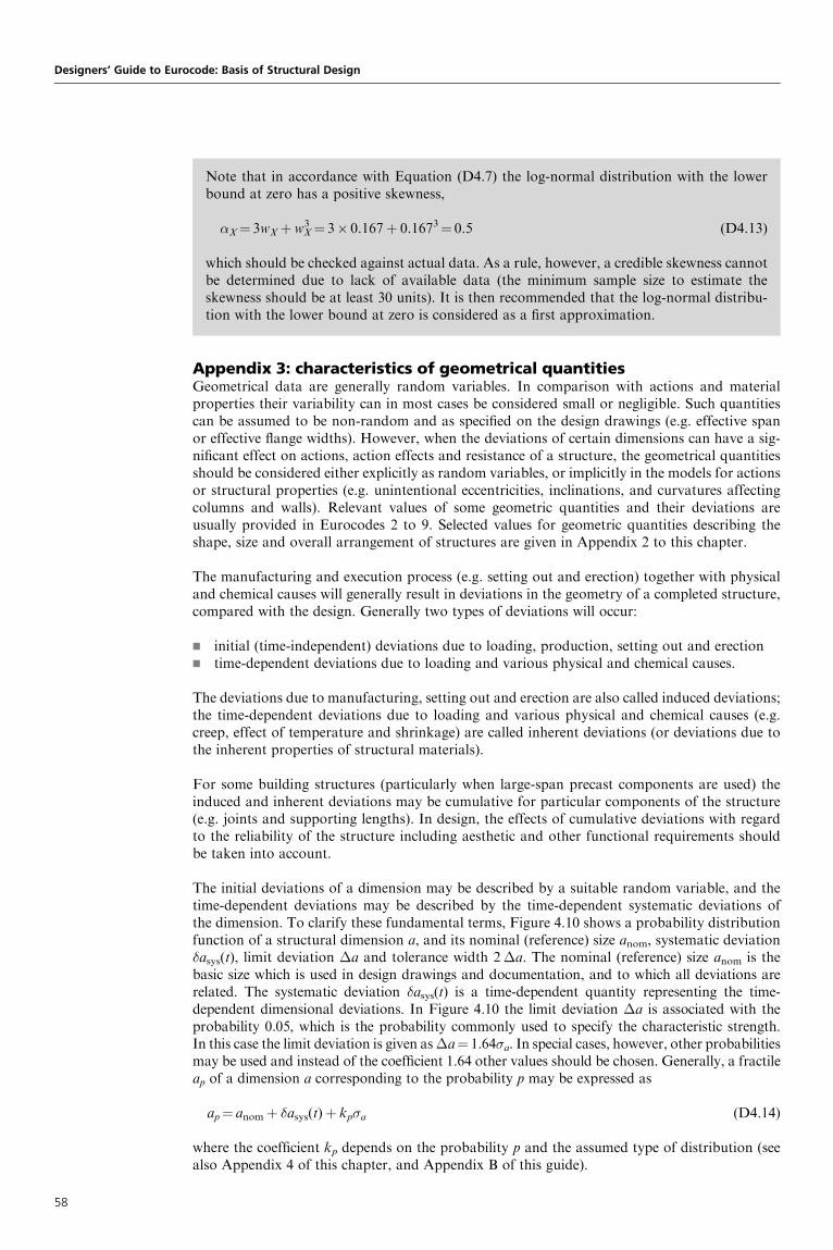
Appendix 3: characteristics of geometrical quantitiesGeometrical data are generally random variables. In comparison with actions and materialproperties their variability can in most cases be considered small or negligible. Such quantitiescan be assumed to be non-random and as specified on the design drawings (e.g. effective spanor effective flange widths). However, when the deviations of certain dimensions can have a sig-nificant effect on actions, action effects and resistance of a structure, the geometrical quantitiesshould be considered either explicitly as random variables, or implicitly in the models for actionsor structural properties (e.g. unintentional eccentricities, inclinations, and curvatures affectingcolumns and walls). Relevant values of some geometric quantities and their deviations areusually provided in Eurocodes 2 to 9. Selected values for geometric quantities describing theshape, size and overall arrangement of structures are given in Appendix 2 to this chapter.
The manufacturing and execution process (e.g. setting out and erection) together with physicaland chemical causes will generally result in deviations in the geometry of a completed structure,compared with the design. Generally two types of deviations will occur:
g initial (time-independent) deviations due to loading, production, setting out and erectiong time-dependent deviations due to loading and various physical and chemical causes.
The deviations due to manufacturing, setting out and erection are also called induced deviations;the time-dependent deviations due to loading and various physical and chemical causes (e.g.creep, effect of temperature and shrinkage) are called inherent deviations (or deviations due tothe inherent properties of structural materials).
For some building structures (particularly when large-span precast components are used) theinduced and inherent deviations may be cumulative for particular components of the structure(e.g. joints and supporting lengths). In design, the effects of cumulative deviations with regardto the reliability of the structure including aesthetic and other functional requirements shouldbe taken into account.
The initial deviations of a dimension may be described by a suitable random variable, and thetime-dependent deviations may be described by the time-dependent systematic deviations ofthe dimension. To clarify these fundamental terms, Figure 4.10 shows a probability distributionfunction of a structural dimension a, and its nominal (reference) size anom, systematic deviation�asys(t), limit deviation �a and tolerance width 2�a. The nominal (reference) size anom is thebasic size which is used in design drawings and documentation, and to which all deviations arerelated. The systematic deviation �asys(t) is a time-dependent quantity representing the time-dependent dimensional deviations. In Figure 4.10 the limit deviation �a is associated with theprobability 0.05, which is the probability commonly used to specify the characteristic strength.In this case the limit deviation is given as�a¼ 1.64�a. In special cases, however, other probabilitiesmay be used and instead of the coefficient 1.64 other values should be chosen. Generally, a fractileap of a dimension a corresponding to the probability p may be expressed as
ap¼ anomþ �asys(t)þ kp�a (D4.14)
where the coefficient kp depends on the probability p and the assumed type of distribution (seealso Appendix 4 of this chapter, and Appendix B of this guide).
Designers’ Guide to Eurocode: Basis of Structural Design
Note that in accordance with Equation (D4.7) the log-normal distribution with the lowerbound at zero has a positive skewness,
�X¼ 3wXþw3X¼ 3� 0.167þ 0.1673¼ 0.5 (D4.13)
which should be checked against actual data. As a rule, however, a credible skewness cannotbe determined due to lack of available data (the minimum sample size to estimate theskewness should be at least 30 units). It is then recommended that the log-normal distribu-tion with the lower bound at zero is considered as a first approximation.
58

Chapter 4. Basic variables
Figure 4.10. Characteristics of a dimension a
Actual size a
anom δasys(t)
Nominal size anom
Tolerance width 2∆a
a
∆a = 1.65σa
–3σa –2σa –1σa µa +1σa +2σa +3σa
5% 5%
∆a = 1.65σa
Example 4.2Consider the simple assembly shown in Figure 4.11. A prefabricated horizontal component iserected on two vertical components. The relevant dimensions describing the setting out,erection and dimensions of the component are obvious from Figure 4.11. The supportinglength b (which is one of the lengths b1 and b2 indicated in Figure 4.11) of the horizontalcomponent has a nominal value bnom¼ 85 mm. Taking into account deviations in thesetting out, manufacture and erection, the supporting length was determined to have anapproximate normal distribution with systematic deviation �asys(t)¼ 0 and standarddeviation �b¼ 12 mm.
It follows from Equation (D4.4) and the data given in Appendix B of this guide that the lower5% fractile of the length is
b0.05¼ 85� 1.64� 12¼ 65 mm (D4.15)
and the upper 95% fractile is
b0.95¼ 85þ 1.64� 12¼ 105 mm (D4.16)
Therefore, with a probability of 0.90 the supporting length will be within the interval 85�20 mm, and the corresponding eccentricity of the loading transmitted by the componentto the supporting vertical member may differ by �10 mm from an assumed value.
59

Appendix 4: tolerances for the overall imperfectionsCompleted structures after erection should satisfy the criteria specified in Table 4.4 andFigures 4.12–4.15. Each criterion should be considered as a separate requirement to be satisfiedindependently of any other tolerance criteria.
Designers’ Guide to Eurocode: Basis of Structural Design
The initial and time-dependent deviations may lead to considerable variations in the shapesand sizes of structures and their parts as follows:
1 in the shape and size of cross-sections, support areas, joints, etc.2 in the shape and size of components3 in the overall shape and size of the structural system.
For cases (1) and (2), where the variation of structural dimensions can affect the safety,serviceability and durability of the structures, specified permitted deviations or tolerancesare given in relevant standards, EN 1992 to EN 1999. These tolerances are denoted asnormal tolerances, and should be taken into account if other smaller or larger tolerancesare not specified in the design. When deviating from EN 1992 to EN 1999 with regard totolerances, care should be taken to ensure that the design considers the implicationsof other deviations with regard to structural reliability. For case (3), some informativetolerances are given in Appendix 2 of this chapter.
Figure 4.11. A horizontal component erected on two vertical components
b1
o1o2
b2
v1
t1 t2
v2
I
d
60

Figure 4.12. Inclination of a column between adjacent floor levels
e
h
e # 0.002h
Figure 4.13. Location of a column at any floor level
e
h2
h3
h1
e # (0.0035 ∑ h)/√n
h
Chapter 4. Basic variables
Table 4.4. Normal tolerances after erection
Criterion Permitted deviation
Deviation of the distance between adjacent columns �5mm
Inclination of a column in a multistorey building in relation to storey height h (see
Figure 4.12)
0.002h
Horizontal deviation of column location in a multistorey building at a floor levelPh from the base, where
Ph is the sum of n relevant storey heights, in relation
to a vertical line to the intended column base location (see Figure 4.13)
0.0035P
h/pn
Inclination of a column of height h in a single-storey building other than a portal
frame and not supporting a crane gantry (see Figure 4.14)
0.0035h
Inclination of columns of height h in a portal frame not supporting a crane gantry
(see Figure 4.15)
Mean: 0.002h
Individual: 0.001h
61
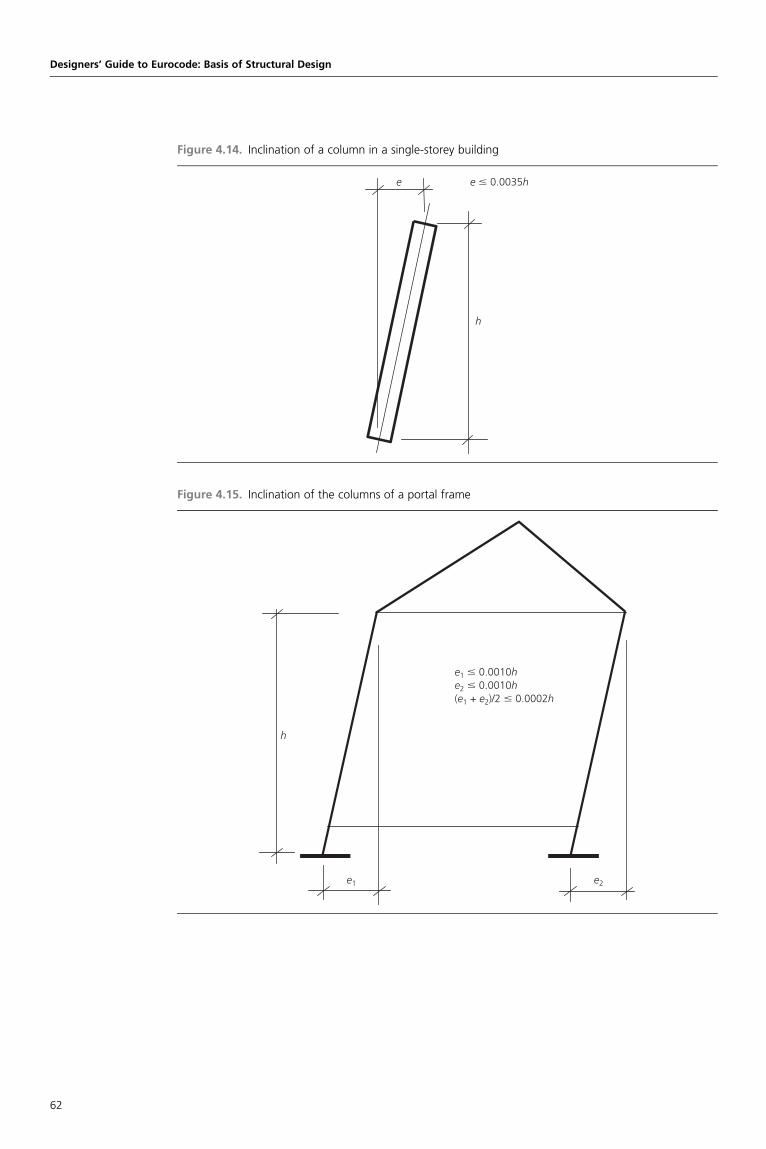
Figure 4.14. Inclination of a column in a single-storey building
e
h
e # 0.0035h
Figure 4.15. Inclination of the columns of a portal frame
e1 e2
h
e1 # 0.0010he2 # 0.0010h(e1 + e2)/2 # 0.0002h
Designers’ Guide to Eurocode: Basis of Structural Design
62

Designers’ Guide to Eurocode: Basis of Structural DesignISBN 978-0-7277-4171-4
ICE Publishing: All rights reserved
http://dx.doi.org/10.1680/bsd.41714.063
Chapter 5
Structural analysis and designassisted by testing
This chapter is concerned with the modelling of building and civil engineering structures for thepurpose of determining action effects and resistances. The material described in this chapter iscovered in Section 5 of EN 1990, in the following clauses:
g Structural analysis Clause 5.1g Design assisted by testing Clause 5.2
5.1. Structural analysis5.1.1 Structural modellingThe Principles and Application Rules presented in Section 5 of EN 1990 primarily deal withthe modelling of structures. Action effects in cross-sections, joints or members determinedthrough structural modelling and analysis can be used to verify the reliability of buildings andcivil engineering works at their various limit states. In design calculations, the structuralresponse to direct and indirect actions, in combination with the effects of environmentalinfluences (e.g. interaction between fire and strength, stress and corrosion), should be generallyconsidered.
The overall structural form of a building or civil engineering structure should be chosen withregard to the requirements of expected use, and for safety and serviceability under expectedactions. It is assumed that the structural system is chosen by appropriately qualified and experi-enced personnel and satisfies all other requirements, for example, concerning execution, qualitycontrol, construction materials, maintenance and use (clause 1.3).
Typically, the structural system comprises three subsystems:
g the main structural system: the load-bearing elements of a building or civil engineeringworks and the way in which these elements function together
g secondary structural elements: for example, beams and purlins that transfer the load to themain system
g other elements: for example, cladding, roofing, partitions or facades that merely transferloads to main and secondary elements.
While ultimate limit state failure of the main structural system can induce a global collapse withmajor consequences, an ultimate limit state failure of secondary or other elements wouldnormally lead to local collapses with minor consequences. Hence, separate structural modelsand reliability levels may be needed for each of these subsystems or their combinations. Forsome structural systems (e.g. for frames with stiff infill elements such as cladding and partitionwalls), interaction between secondary or other elements and the main structural system shouldbe considered.
According to clauses 5.1.1(1)P and 5.1.1(2)P, the appropriate design models should involverelevant variables, and should be appropriate for predicting the structural behaviour andthe limit states considered with an acceptable level of accuracy. The models should bebased on established engineering theory and practice, and verified experimentally if necessary(clause 5.1.1(3)P)). EN 1990 places very strong emphasis on clause 5.1.1(3)P.
Clause 5.1.1
Clause 1.3
Clause 5.1.1(1)P
Clause 5.1.1(2)P
Clause 5.1.1(3)P
63

Clause 5.1.2(1)P
Various assumptions will be necessary, such as those concerning the force–deformationor stress–strain relationships, distribution of strain in cross-sections and adequate boundary condi-tions. Experimental verification may be needed, particularly for new structural systems andmaterials, or where new theories or numerical methods are being used to analyse the structure.
Generally, any structural model should be regarded as an idealisation of the structural system.A simplified model should take account of significant factors and neglect the less importantones. The significant factors which may affect the choice of a structural model generallyinclude the following:
g geometric properties (e.g. structural configuration, spans, cross-sectional dimensions,deviations, imperfections and expected deformations)
g material properties (e.g. strength, constitutive relations, time and stress state dependence,plasticity, temperature and moisture dependence)
g actions (e.g. direct or indirect, variation in time, spatial variation, and static or dynamic).
The appropriate structural model should be chosen based on previous experience and knowledgeof structural behaviour. The sophistication of the model should take into account the intendeduse of the results, and will normally involve consideration of the appropriate limit states, thetype of results and the structural response expected. Often, a simple global analysis with equiva-lent properties can be used to identify areas which need more complex and refined modelling.
Depending on the overall structural configuration, the structure may be considered as a three-dimensional system or as a system of planar frames and/or beams. For example, a structurewith no significant torsional response may perhaps be considered as consisting of a set ofplanar frames. The investigation of torsional response is important for structures wherecentres of stiffness and mass do not coincide either by design, or unintentionally(e.g. imperfections); for example, continuous flat slabs supported directly by columns and struc-tures asymmetric in stiffness and/or mass when the three-dimensional nature of the problemneeds to be considered. In many cases, the form of the anticipated structural deformations dueto given actions can clearly indicate a suitable simplification of the structure and therefore anappropriate structural model.
When considering the stability of the structure, it is not only individual members which should bedealt with but also the whole structure: a structure properly designed with respect to individualmembers can still be susceptible to overall instability as a whole (e.g. torsional buckling of auniform-lattice tower crane column).
5.1.2 Static actionsAccording to clause 5.1.2(1)P the modelling for static actions should be based (Principle) on anappropriate choice of the force–deformation relationships of the members and their connections,and between members and the ground. In almost all design calculations some assumptionsconcerning these relationships between forces and deformations are necessary. Generally, suchassumptions are dependent on the chosen design situations, limit states and load cases beingconsidered.
The theory of plasticity which assumes the development of plastic hinges in beams, and yield linesin slabs, should be used carefully for the following reasons:
g the deformation needed to ensure plastic behaviour of the structure may not be acceptablewith regard to serviceability limit states, particularly for long-span frames and continuousbeams
g these deformations should not, generally, be frequently repeated to avoid so-called low-cyclic fatigue
g special attention should be paid to structures in which load-carrying capacity is limited bybrittle failure or instability.
Normally, the action effects and the structural resistance are calculated separately using differentdesign models. These models should, in principle, be mutually consistent. However, in many
Designers’ Guide to Eurocode: Basis of Structural Design
64

cases, this rule may be modified in order to simplify the analysis. For example, while the analysisof a frame or continuous beam for action effects usually assumes the theory of elasticity, thestructural resistance of cross-sections, joints or members may be determined taking intoaccount various non-linear and inelastic properties of the materials.
Designers’ attention is drawn to the fact that the boundary conditions applied to the model are asimportant as the structural model itself (clause 5.1.2(2)P). This is particularly true in the case ofcomplex finite-element analyses, and the design boundary conditions should accurately representthe real boundary conditions in the structure after execution.
According to EN 1990, the effects of displacements and deformations (i.e. second-order effects inthe analysis of structures) should be taken into account in the context of ultimate limit stateverifications (including static equilibrium) if they result in a significant increase in the effectsof actions (clause 5.1.2(3)P).
BackgroundIn the previous version of the Eurocode (ENV 1991-1), an increase of more than 10% inthe effects of actions was proposed, but it was recognised that such a value depends onthe particular construction and/or its structural material.
The second-order effects may be taken into account by assuming equivalent initial imperfectionsand by performing a proper geometrical non-linear analysis. Alternatively, a set of additionalnon-linear forces, resulting from the deformations that correspond to collapse conditions, canbe introduced into a first-order analysis.
Generally, two types of second-order effects may be recognised:
g overall second-order effects (effects of structural sway)g member second-order effects.
A structure may be classified as non-sway, and the overall second-order effects neglected:
g if the increase of the relevant bending moments or sway shear due to second-orderdeformations is less than 10% of the first-order bending moment, or the storey shear,respectively
g if the axial forces within the structure do not exceed 10% of the theoretical buckling load.
In the case of regular steel or concrete frames, the overall analysis may be based on a first-ordermethod, and then the member analysis can take account of both overall and member second-order effects. This procedure should not be used in asymmetric or unusual cases.
Design models used to verify serviceability limit states and fatigue are usually based on the linear-elastic behaviour of the structural material, while those used to verify the ultimate limit statesoften take account of non-linear properties and post-critical behaviour of structures. However,EN 1990 states that indirect actions should be taken into account in linear-elastic analysis,directly or as equivalent forces, or in non-linear analysis, directly as imposed deformations(clause 5.1.2(4)P). In particular, when phenomena such as differential settlement and whole-structure stability may affect the structural design under static conditions, the modelling of astructure should also include the consideration of the foundation, and this includes the soil.Soil–structure interaction can be addressed through either a simultaneous analysis of thesoil–structure system or a separate analysis of each system.
5.1.3 Dynamic actionsIn general, dynamic actions (i.e. those actions that ‘cause significant acceleration of the structureor structural members’ (see clause 1.5.3.12)) interact with the relevant structure or structuralmembers which need, consequently, to be correctly modelled. The modelling should take intoaccount – in addition to masses, strengths, stiffness, damping characteristics and properties of
Clause 5.1.2(2)P
Clause 5.1.2(3)P
Clause 5.1.2(4)P
Clause 1.5.3.12
Chapter 5. Structural analysis and design assisted by testing
65

Clause 5.1.3(1)P
Clause 5.1.3(2)P
Clause 5.1.3(3)
Clause 5.1.3(4)
Clause 5.1.3(5)
Clause 5.1.3(6)
Clause 5.1.3(7)
non-structural members (clause 5.1.3(1)P) – accurate and realistic boundary conditions (clause5.1.3(2)P) as for static actions. For example, if the dynamic actions are caused by the motionof masses which are themselves being supported by the structure (e.g. people, machinery orvehicles), these masses should be considered in the analysis as they may affect the dynamicproperties of lightweight systems.
Most of the actions as specified in EN 1990 are transformed into equivalent static actions. Theseequivalent forces are defined such that their effects are the same as, or similar to, the effects ofthe actual dynamic actions. When dynamic actions are simulated by quasi-static actions, thedynamic parts are considered either by including them in the static values, or by applyingequivalent dynamic amplification factors to the static actions (clause 5.1.3(3)). For someequivalent dynamic amplification factors, the natural frequencies have to be determined.
In the case of dynamic effects caused by significant soil–structure interaction (e.g. thetransmission of traffic vibrations to buildings), the contribution of the soil may be modelled,for example, by appropriate equivalent springs and dampers. The soil may also be approximatedwith a discrete model (clause 5.1.3(4)).
In some cases (e.g. for wind-induced vibrations, seismic actions or actions of pedestrians onfootbridges), the actions are significantly controlled by the structural response, and can thereforebe defined, as well as their effects, only when the dynamic behaviour of the structure has beenestimated by using a modal analysis. A linear material and a linear geometric behaviour areusually acceptable (clause 5.1.3(5)) for such a modal analysis. Non-linear material propertiescan be approximated using iterative methods together with the secant stiffness (Figure 5.1) asrelated to the response level.
For structures where only the fundamental mode is relevant, an explicit modal analysis may bereplaced by an analysis with equivalent static actions, depending on the mode shape, naturalfrequency and damping. Structural response to dynamic actions may be determined in termsof time histories or in the frequency domain (clause 5.1.3(6)).
Particular attention should be given to those dynamic actions which may cause vibration thatmay infringe serviceability requirements, including comfort criteria. Guidance for assessingthese limit states is given in Annex A of EN 1990 and in the design Eurocodes (clause 5.1.3(7)).
Designers’ Guide to Eurocode: Basis of Structural Design
Figure 5.1. Typical curve �¼ f(") for concrete under compression, and definition of the secant modulus
of elasticity
Tangent of modulus of elasticity
Secant modulus of elasticity Ec0 for σ0 < 0.5fcd
Secant modulus of elasticity Ec1 for σ1 < 0.5fcd
Strain ε0
Stress σ
0.5fcd
fcd
σ0
σ1
66

5.1.4 Fire designClause 5.1.4 provides only basic Principles and Application Rules for the modelling of thermalactions on structures exposed to fire. A more detailed description of thermal actions due tofire and modelling for the structural design of buildings and civil engineering works isprovided in Part 1-2 of Eurocode 1 and relevant parts of the design Eurocodes 2 to 9. Asstated in clause 3.2(2)P, the thermal actions on structures from fire are classified as accidentalactions and considered in the accidental design situation (see also EN 1990, Section 6;EN 1991-1-2; and Chapter 6 of this guide).
According to clause 5.1.4(1)P, appropriate models for the fire situation, which should be used toperform the structural fire design analysis, involve three fundamental aspects characterising theappropriate accidental design situation:
g design fire scenariog temperature evolutiong structural behaviour at elevated temperatures.
Clause 5.1.4(2) needs no further explanation.
Thermal and mechanical actions to be considered in the fire situations are specified in EN 1991-1-2, where two procedures are distinguished (clause 5.1.4(3)):
g nominal fire exposureg modelled fire exposure.
In most cases, thermal actions on structures exposed to fire are given in terms of nominaltemperature–time curves. These curves are applied for the specified period for which the structureis designed, using prescriptive rules or calculation models. Appropriate data for these actions aregiven in the main text of EN 1991-1-2.
Parametric temperature–time curves are calculated on the basis of physical parameters for whichstructures are designed using calculation models. Some data and models for physically basedthermal actions are given in the informative annexes of EN 1991-1-2.
If they are likely to act in the fire situation, direct and indirect actions should be considered asfor normal temperature design. Section 4 of EN 1991-1-2 provides guidance regarding thesimultaneity of actions and combination rules applicable to structures exposed to fire. Thisguidance concerns permanent actions, variable actions and additional actions due to the collapseof structural elements and heavy machinery. For the special cases, where indirect actions neednot be considered, simplified rules for combining of actions are also indicated in EN 1991-1-2.
Thermal and structural models for various construction materials, given in the design Euro-codes 2 to 9, should be used to analyse the structural behaviour at elevated temperatures(clause 5.1.4(4)).
Clause 5.1.4(5) gives some simplified rules and assumptions concerning the thermal models andstructural models in fire exposure, which may be used when relevant to the specific material andthe method of assessment. Further, clause 5.1.4(6) allows consideration of the behaviour ofmaterials or sections at elevated temperatures.
5.2. Design assisted by testingThe Eurocode system permits a design based on a combination of tests and calculations forbuilding and civil engineering structures (clause 5.2(1)). This clause is an introduction toAnnex D of EN 1990 (see Chapter 10 of this guide), which gives guidance on the planning andevaluation of tests to be carried out in connection with structural design, where the numberof tests is sufficient for a meaningful statistical interpretation of their results. Basicstatistical techniques for estimating fractiles is briefly described in Appendix C of this guide.Some of the procedures described in Chapter 10 may also be useful for the assessment ofexisting structures.
Clause 5.1.4
Clause 3.2(2)P
Clause 5.1.4(1)P
Clause 5.1.4(2)
Clause 5.1.4(3)
Clause 5.1.4(4)
Clause 5.1.4(5)
Clause 5.1.4(6)
Clause 5.2(1)
Chapter 5. Structural analysis and design assisted by testing
67

Clause 5.2(2)P
Clause 5.2(3)
Design assisted by testing is a procedure using physical testing (e.g. models, prototypes or in situ)for establishing design values. Such procedures can be used in particular for those cases where thecalculation rules or material properties given in the design Eurocodes are considered insufficient,or where a more economical design may result.
An essential requirement for using design assisted by testing is given in clause 5.2(2)P. Testsshould be set up and evaluated in such a way that the structure has the same level of reliability,with respect to all possible limit states and design situations, as would be achieved by designusing the design Eurocodes. Hence, all uncertainties, such as those due to the conversion ofexperimental results and those arising from the statistical uncertainty associated with designassisted by testing (e.g. the application of experimental results, and any statistical uncertaintiesdue to the sample size) should be taken into account. Furthermore, the conditions duringtesting should so far as possible be representative of those which can be expected to arise inpractice.
Moreover, partial factors comparable to those used in the design Eurocodes should be used(clause 5.2(3)): thus, EN 1990 clearly stipulates that design assisted by testing is not a possibilitygiven to designers to reduce strongly partial factors.
Designers’ Guide to Eurocode: Basis of Structural Design
68
Designers’ Guide to Eurocode: Basis of Structural DesignISBN 978-0-7277-4171-4
ICE Publishing: All rights reserved
http://dx.doi.org/10.1680/bsd.41714.069
Chapter 6
Verification by the partialfactor method
This chapter is concerned with the verification of building structures and civil engineering worksusing the partial factor method. The material described in this chapter is covered in Section 6 ofEN 1990, and is completed by Annex A of EN 1990 for various types of construction works. Atthe present stage, only Annex A1, ‘Application for buildings’, is available, and is discussed inChapter 7. The material described in this chapter is covered in Section 6 as follows:
g General Clause 6.1g Limitations Clause 6.2g Design values Clause 6.3g Ultimate limit states Clause 6.4g Serviceability limit states Clause 6.5
6.1. GeneralAn assessment of the reliability of buildings and civil engineering works in the Eurocodes is basedon the concept of limit states and their verification by the partial factor method. Using thismethod, a structure is considered to be reliable if no relevant limit state is exceeded for allselected design situations when using the design values of the basic variables (actions, materialproperties and geometrical data) in the design models.
EN 1990 requires the consideration of selected design situations and the identification of criticalload cases. For each of the critical load cases, the design values of the effects of actions underconsideration should be determined. A load case identifies compatible load arrangements, setsof deformations and imperfections which should be considered simultaneously for a particularverification (clause 6.1(1)P).
‘Actions that cannot occur simultaneously, for example due to physical reasons, should not beconsidered together in combination’ (clause 6.1(2)). This rule should be interpreted using goodengineering judgement. For example, a maximum snow load cannot physically exist on aheated greenhouse.
For the verification of structural reliability, the following essential elements are always taken intoaccount:
g the various design models for the verification of the ultimate and serviceability limit statesg the design values of the appropriate basic variables (actions, material properties and
geometrical data), derived from their characteristic or other representative values, and aset of partial factors (�) and coefficients (clause 6.1(3)).
In cases where design values of basic variables cannot be derived from characteristic values, inparticular because of lack of statistical data, appropriate design values are then determineddirectly (e.g. design values of actions for accidental design situations), and in such casesconservative values should be chosen (clause 6.1(4)).
For other cases (e.g. when the design procedure is performed on the basis of tests), the designvalue may be determined directly from available statistical data (for more details, see Annex D
Clause 6.1(1)P
Clause 6.1(2)
Clause 6.1(3)
Clause 6.1(4)
69

Clause 6.1(5)
Clause 6.2(1)
of EN 1990 and Chapter 10 of this guide). The design values should be selected so that they givethe same level of reliability, as implied by the partial factors given or recommended in EN 1990(clause 6.1(5)). EN 1990 firmly states that design assisted by testing should not be considered as ameans to lower the reliability level of a construction. It should be used, when appropriate, inorder to obtain a better understanding of the statistical properties of a basic variable, and toassess more accurately a design value in accordance with the levels defined in the Eurocodes.
6.2. LimitationsThe Application Rules in EN 1990 are limited to ultimate limit states and serviceability limitstates for structures subjected to static loading and quasi-static loading where the dynamiceffects are assessed using equivalent quasi-static loads and dynamic amplification factors (e.g.in the case of wind or traffic loads). Specific rules for non-linear and dynamic analysis andfatigue are not comprehensively covered in EN 1990, but are provided in the design Eurocodes1 to 9 (clause 6.2(1)).
6.3. Design valuesFigure 6.1 gives a general overview of the system of partial factors used in the Eurocodes (see alsoAnnex C to EN 1990 and Chapter 9 of this guide, which give a simplified representation of thepartial factor system for the most common ultimate limit states of resistance).
6.3.1 Design values of actionsThe design value Fd of an action F can be expressed in general terms as
Fd ¼ �f Frep (6.1a)
Designers’ Guide to Eurocode: Basis of Structural Design
Figure 6.1. General overview of the partial factor system in the Eurocodes
Representation of actionsψFk, i
Design values of actionsFd,i = γf,i ψFk,i
Design values ofgeometrical data ad
Characteristic values of material orproduct properties
Xk
Effects of actionsE (γf,i ψFk,i )
Design values of material orproduct properties
× γf,i
× γSd
Variants
Xd,i = Xk, iηi
γm,i
Design value of effects of actionsEd = γSdE(γf,i ψFk,i ; ad)
Design resistance
Rd = R ( Xk,i ; ad)1γRd
ηi
γm,i
Rd = R (η1Xk,1; Xk,i ; ad)1γM,1
ηi γm,1
γm,i
Ed = γF,1E (ψFk,1; ψFk, i; ad)γf,i
γf,1
Ed = E(γf,i ψFk,i ; ad) Rd = R ( Xk,i ; ad)ηi
γM,i
Rd = Rk
γM
×ηi
γm,i
×1
γRd
70

Frep represents the value taken into account in the relevant combination of actions. It can be thecharacteristic value Fk of the action (i.e. the main representative value), the combination value 0Fk or the frequent or the quasi-permanent values ( 1Fk, 2Fk). Therefore, EN 1990 adoptsthe symbolic representation given in expression (6.1b) (clause 6.3.1(1)):
Frep ¼ Fk (6.1b)
where ¼ 1 or 0, 1 or 2. And ‘�f is a partial factor for the action which takes account of thepossibilities of unfavourable deviations of the action values from the representative values.’
The system of reliability safety elements (� factors, factors and characteristic values of actions Fk)is applicable to limit states only where the magnitude of load values governs the reliability (one-dimensional actions). When actions are multidimensional in that they comprise more than oneparameter (e.g. fatigue parameters, the stress amplitude ��, the number of cycles N and theslope constant of a fatigue strength curve m; see Eurocode 3 and Appendix 1 to Chapter 4 ofthis guide), and when the effects of these parameters are non-linear (e.g.
P��i
mNi), both therepresentative values and design values of actions depend on the way these parameters influencethe limit state. For such cases, detailed rules are given in the design Eurocodes 1 to 9.
BackgroundIn ENV 1991-1, ‘Basis of design’, the design values of actions were directly based on the useof �F factors incorporating also inaccuracies of the action models (see below). In order tosimplify the presentation, it has been decided to use separate factors to cover, on onehand, uncertainty on the value of the action itself, and, on the other hand, uncertainty inmodelling the effects of actions.
In some cases, the design values of actions are assessed taking into account the response of thestructure. In other cases (e.g. for seismic actions or in the case of ground–structure interaction),the design value may depend on the relevant parameters for the structural behaviour. Thequestion of the design values of actions is then treated in the relevant design Eurocodes(clause 6.3.1(2)).
6.3.2 Design values of the effects of actionsThe effects of actions E are the response of the structural members (e.g. internal force, moment,stress or strain) or of the whole structure (e.g. deflection or rotation) to the actions imposed on it,the responses of the structure to the actions being compatible with the model used to define thelimit state. The effects of the actions E depend on the actions F, the geometrical properties aand, in some cases, the material properties X. For example, when E(.) represents the bendingmoment in a given cross-section of a structural member, this bending moment may be causedby self-weight, imposed loads, wind actions on the structure, etc.
Where material properties are not involved, and for a specific load case, the expression of thedesign value Ed of the effects of actions can be given in general terms (clause 6.3.2(1)), as
Ed ¼ �SdE{�f,iFrep,i; ad} i� 1 (6.2)
where �Sd is a partial factor for model uncertainties (models of the effects of actions and, inparticular cases, models of actions). ad represents the design values of geometrical data (seeSection 6.3.4).
Expression (6.2) is not the most frequently used. For the design of common structures, thefollowing simplification (expression (6.2a)) is adopted by EN 1990 (clause 6.3.2(2)):
Ed ¼ E{�F,iFrep,i; ad} i� 1 (6.2a)
with
�F,i ¼ �Sd�f,i (6.2b)
Expression (6.2b) is also commonly met in geotechnical problems (see Eurocode 7).
Clause 6.3.1(1)
Clause 6.3.1(2)
Clause 6.3.2(1)
Clause 6.3.2(2)
Chapter 6. Verification by the partial factor method
71

Clause 6.3.2(2)
Clause 6.3.2(3)P
Clause 6.3.2(4)
The decomposition �F ¼ �Sd�f may be important when the partial factor design is substituted bymore sophisticated numerical simulations of actions and action effects (e.g. by simulation of thedynamic wind effects on buildings, where the magnitude of masses from permanent and variableloads have to be determined together with wind actions). In that case, only �f applies.
As explained in the note to clause 6.3.2(2), another expression may be used where relevant, inwhich a particular �F,1 factor is applied to the whole effect of the combination of actions inwhich the actions are multiplied by appropriate factors:
Ed ¼ �F ;1E Fk;1;�f ;i�f ;1
Frep;i; ad
� �i > 1 ðD6:1Þ
BackgroundAs previously explained, numerical values of �F factors have been widely unified. For thisreason, in some cases, �Sd does not only cover model uncertainty on effects of actions butalso includes an element of reliability on the model of one action itself.
Expression (D6.1) can be used for partial factor design based on finite-element analysis or forsome special geotechnical problems (e.g. for the calculation of tunnel vaults).
In clause 6.3.2(3)P a distinction is made between favourable and unfavourable permanentactions: the words ‘favourable’ and ‘unfavourable’ should be understood with respect to theeffect under consideration. In particular, where a variable action acts, permanent actionsshould be classified as ‘unfavourable’, or ‘favourable’ whether they act ‘unfavourably’ with, or‘favourably’ opposite to, the variable action. In such cases, and if permanent actions are notfrom the same source (see note 3 to Table A1.2(B) in EN 1990), they are multipliedby different partial factors: �G,sup for ‘unfavourable’ permanent actions and �G,inf for‘favourable’ permanent actions (Figure 6.2).
Specific problems may arise when using the partial factor method in the case of structural non-linear analysis (i.e. when the action effect is not proportional to the action); for non-linearanalysis, the partial factors should be cautiously applied. In the case of a single predominantaction F, EN 1990 proposes the following simplified safe-sided rules (clause 6.3.2(4)):
g When the action effect E(F ) increases more than the action, the partial factor �F should beapplied to the representative value of the action (Figure 6.3(a)):
Ed ¼ E(�FFk) (D6.2)
g When the action effect E(F ) increases less than the action, the partial factor �F should beapplied to the action effect of the representative value of the action (Figure 6.3(b)):
Ed ¼ �FE(Fk) (D6.3)
Designers’ Guide to Eurocode: Basis of Structural Design
Figure 6.2. Examples of the application of permanent and variable actions. (a) qg and Q act together
(unfavourably): the effects of the permanent action qg should be multiplied by �G,sup. (b) Depending on
the cross-section under consideration, qg and Q act together or opposite to each other: the effects of the
permanent action qg should be multiplied by �G,sup or �G,inf
Q (variable action) Q (variable action)
qg (permanent action)qg (permanent action)
(a) (b)
72

In practice, the situation may be more complex, and, according to EN 1990 (clause 6.3.2(5)),more refined methods, given in the relevant EN 1991 to EN 1999 standards (e.g. for prestressedstructures), should be used in preference to the previous one. For example, for the case where twoactions are involved, the first rule becomes (Figure 6.4(a))
Ed ¼ E(�GGkþ �QQk) (D6.4)
with �G ¼ �Sd�g and �Q ¼ �Sd�q.
Concerning the second rule (Figure 6.4(b)), a more refined approach would involve the modelfactor �Sd in the combined effect of actions G and Q taken with their design value, that is,
Ed ¼ �SdE(�gGk; �qQk) (D6.5)
6.3.3 Design values of material or product propertiesThe design value of a resistance may be determined by various means, including:
g empirical relationships involving measured physical properties or chemical composition(e.g. the composition of a high-strength concrete with silica fume)
g from previous experienceg from values given in appropriate documents such as European standards.
Generally, the design value Xd of a material or a product property X is determined from the char-acteristic value Xk using the partial factor for the material or product property �m and, ifrelevant, the conversion factor � in accordance with the relationship (clause 6.3.3(1))
Xd ¼ �Xk
�mð6:3Þ
where � represents the mean value of the conversion factor that takes into account volumeand scale effects, the effects of moisture and temperature, etc. The conversion factor may beincorporated in the characteristic value (clause 6.3.3(2)).
From a conceptual point of view, � should also take into account the effects of load duration. Inpractice, these effects are taken into account separately as, for example, in the case of concretewith factors �cc and �ct (see Eurocode 2) applicable to the characteristic values of the compressivestrength,
fcd ¼ �cc
fck�c
ðD6:6aÞ
Clause 6.3.2(5)
Clause 6.3.3(1)
Clause 6.3.3(2)
Chapter 6. Verification by the partial factor method
Figure 6.3. Application of the partial factor �F in the case of non-linear analysis (single action).
(a) The non-linear action effect increases more than the linear action effect proportional to the action.
(b) The non-linear action effect increases less than the linear action effect proportional to the action
E(F ) E(F )
E(γF Fk)
Fk γF Fk Fk E–1(γF E(Fk))
E (γF Fk) < γF E(Fk)E (γF Fk) > γF E(Fk)
E(Fk)γF E(Fk)
x γF
x γF
E(Fk)
F F
(a) (b)
73

Clause 6.3.4(1)
and tensile strength,
fctd ¼ �ct
fctk;0:05�c
ðD6:6bÞ
The partial factor �m is intended to cover the possibility of unfavourable deviations of thematerial or product property from its characteristic value and the random part of the conversionfactor. Indeed, the conversion factor may be considered as a random variable: its scatter aroundthe mean value is assumed to be taken into account in the �m factor.
6.3.4 Design values of geometrical dataThe variability in geometrical quantities is usually less significant than the variability in actionsand material or product properties, and in many cases is negligible. Consequently, design valuesof geometrical data are generally represented by the nominal value (clause 6.3.4(1)):
ad ¼ anom (6.4)
The nominal (reference) dimension anom is the basic dimension which is used in design drawingsand documentation. All deviations of the geometric quantities are related to it. The geometricalvalue anom comprises not only the geometrical data as lengths and widths of a frame but alsorepresents the so-called ‘perfect geometry’, in that sway imperfections of the frame or curvatureimperfections of the members or inaccuracy of the excavation depth in front of sheet pilings are
Designers’ Guide to Eurocode: Basis of Structural Design
Figure 6.4. Application of the model factor �Sd in the case of non-linear analysis (two actions).
(a) The non-linear action effect increases more than the linear action effect proportional to the action.
(b) The non-linear action effect increases less than the linear action effect proportional to the action.
(The symbol ‘þ’ denotes ‘to be combined with’)
E(γSd(γgGk ‘+’ γqQk))
E(γSd(γgGk ‘+’ γqQk)) > γSdE(γgGk ‘+’ γqQk)
γgGk ‘+’ γqQk γSd(γgGk ‘+’ γqQk)
γgGk ‘+’ γqQk E–1(γSdE (γgGk ‘+’ γqQk))
E(γg Gk ‘+’ γqQk)
γSdE(γgGk ‘+’ γqQk)
E(γg Gk ‘+’ γqQk)
E(G ‘+’ Q)
E(G ‘+’ Q)
x γSd
x γSd
(a)
E(γSd(γgGk ‘+’ γqQk)) < γSdE(γgGk ‘+’ γqQk)
(b)
G ‘+’ Q
G ‘+’ Q
74

not considered. Such imperfections are reflected in the ‘additive reliability elements’ �a, asexplained below. The design Eurocodes 1 to 9 give appropriate specifications.
Where deviations in the geometrical data have a significant effect on the reliability of astructure (e.g. slender columns or thin silo walls), the geometrical design values are defined by(clause 6.3.4(2)P)
ad ¼ anomþ�a (6.5)
where �a takes account of the possibility of unfavourable deviations from the characteristic ornominal values and the cumulative effect of a simultaneous occurrence of several geometricaldeviations. It should be noted that �a is introduced only where the influence of deviations iscritical (e.g. imperfections in buckling analysis). Values of �a are given in Eurocodes 2 to 9.
6.3.5 Design resistanceThe general expression of the design resistance of a structural member is (clause 6.3.5(1))
Rd ¼ 1
�Rd
RfXd;i; adg ¼ 1
�Rd
R �iXk;i
�m;i; ad
� �i � 1 ð6:6Þ
where �Rd is a partial factor covering uncertainty in the resistance model, plus geometricdeviations if these are not modelled explicitly (see clause 6.3.4(2)), and Xd,i is the design valueof material property i.
Variations of expression (6.6) are given in the design Eurocodes 1 to 9, because the characteristicvalue of the resistance Rk for a given material, or way of construction, may be expressed invarious ways, for example:
g as the resistance of a member (e.g. the beam–column resistance), where Rk may be a linearor a non-linear function of many geometrical parameters, material parameters andparameters for structural and geometrical imperfections
g as the resistance of a cross-section, generally expressed in terms of a linear or non-linearinteraction formula comprising geometrical data and material data compatible with theaction effects
g as a local resistance in terms of stresses, strains, stress intensity factors (or rotationcapacity), etc.
In a general manner, the characteristic value Rk of the resistance of a structural member is afunction of one or more parameters which may be expressed in terms of individual characteristicvalues Xk,i, or individual nominal values Xnom, j, so that
Rk ¼ R(Xk,i, Xnom, j, anom) (D6.7)
Depending on the case, Xk, Xnom, anom or Rk may be described as a property of a product in amaterial or product standard. The particular property may therefore be controlled by testing(see Chapter 10) in order to verify that the definition of Rk as a characteristic value (a givenfractile of the distribution of R) is fulfilled.
In some cases, the parameter Xk represents a sample property that is verified by testing; however,the value of the in-situ property of the parameter in the structure may be different from the valuemeasured on samples, and a conversion factor should then be used in Rk.
The following simplification of expression (6.6) is used in EN 1990 and EN 1992, for example, inthe case of concrete structures (clause 6.3.5(2)):
Rd ¼ R �iXk;i
�M;i
; ad
� �i � 1 ð6:6aÞ
where
�M,i ¼ �Rd�m,i (6.6b)
Clause 6.3.4(2)P
Clause 6.3.5(1)
Clause 6.3.4(2)
Clause 6.3.5(2)
Chapter 6. Verification by the partial factor method
75

Clause 6.3.5(3)
Clause 6.3.5(4)
Clause 6.4.1(1)P
In the case of steel structures, the design value Rd is generally obtained directly from thecharacteristic value of a material or product resistance (clause 6.3.5(3)):
Rd ¼ Rk
�Mð6:6cÞ
where bothRk and �M are generally determined from test evaluations using Annex D of EN 1990.A rigid definition of Rk as a fractile (e.g. the 5% fractile) would often lead to a variety of �Mfactors depending on the resistance considered. Therefore, a unique �M factor is used (this hasbeen adopted by the FIB in order to apply the same partial factor for bending and for shear)for a group of resistances, and the fractile of Rk is modified in such a way that the reliabilitytarget for Rd is reached.
For members consisting of different materials that act together in a composite action (e.g.concrete and steel), the resistance Rk may make reference to material properties Xk,1 and Xk,2
with different definitions (clause 6.3.5(4)). In this case one or both of these properties shouldbe modified, for example, with
X�k;1 ¼ Xk;1
X�k;2 ¼
Xk;2
�m;2�m;1
so that
Rd ¼ 1
�M;1
Rk �1Xk;1; �2Xk;2
�m;2�m;1; ad
� �ð6:6d Þ
Such an expression may be used, in particular, for finite-element analysis. Deterioration effects(e.g. loss of material due to corrosion) may be considered by introducing a subtractive reliabilityelement, for geometrical values for cross-sections, so that
ad ¼ anom��a
In some cases (e.g. in geotechnical design), Rd is determined without the characteristic value Rk,so that
Rd ¼ 1
�Rd
Rk
Xm
�m; ad
� �ðD6:8Þ
6.4. Ultimate limit states6.4.1 GeneralTo avoid any deviating interpretation of the ultimate limit states, it was decided by the EN 1990project team, in liaison with experts responsible for ‘Eurocode 7: Geotechnical design’, to:
g Avoid the introduction of the former ‘cases’ or of ‘types of limit states’.g Simply describe the major failure modes in the following way (clause 6.4.1(1)P):
a) EQU: Loss of static equilibrium of the structure or any part of it considered as a rigidbody, where:– minor variations in the value or the spatial distribution of actions from a single source
are significant, and– the strengths of construction materials or ground are generally not governing;
b) STR: Internal failure or excessive deformation of the structure or structural members,including footings, piles, basement walls, etc., where the strength of construction materialsof the structure governs;
c) GEO: Failure or excessive deformation of the ground where the strength of soil or rockare significant in providing resistance;
d ) FAT: Fatigue failure of the structure or structural members.
Designers’ Guide to Eurocode: Basis of Structural Design
76

BackgroundIn ENV 1991-1, three basic ‘cases’ of ultimate limit state verifications were consideredseparately as relevant, corresponding to the following definitions:
g loss of equilibrium where strength of the material and/or ground are insignificant (caseA in ENV 1991-1)
g failure of structure or structural elements, including those of the footing, piles,basement walls, etc., where the strength of the structural material is decisive (case B inENV 1991-1)
g failure in the ground, where strength of the ground is decisive (case C in ENV 1991-1).
Several guides and background documents gave different interpretations of these variouscases, showing that their meaning was not fully clear. More precisely, in some publications,these cases were sometimes confused with load cases, which were inconsistent with thefollowing definition: ’Compatible load arrangements, sets of deformations and imperfec-tions considered simultaneously with fixed variable actions and permanent actions for aparticular verification’. Moreover, the sentence (in ENV 1991-1) ‘the design should beverified for each case A, B and C separately as relevant’, was considered unclear becauseit was sometimes thought that the most unfavourable of all combinations of actions basedon the sets of � factors corresponding to cases A, B and C had to be taken into accountfor each particular problem.
The reader should consider that limit states of a structure are idealised states beyond which thestructure under consideration does not meet certain structural or functional design requirements.The objective of the verifications is to check that such states cannot be reached or exceeded with agiven probability.
The design values are assessed in accordance with Annex A (clause 6.4.1(2)P) of EN 1990 (seeChapter 7).
Limit states EQUNormally, in accordance with the definition, limit states of static equilibrium are independent ofthe strength of the material. In most cases, exceeding the limit state causes immediate collapse.Thus, a loss of static equilibrium is an ultimate limit state. Examples of such limit states arenot met very frequently. Figure 6.5 illustrates an example of a bridge deck launched with acounterweight where a loss of static equilibrium may be possible.
In the case of foundations, limit states of static equilibrium nearly always represent the idealisa-tion of more complex limit states. Figure 6.6 shows an example of a retaining wall with a footinglying directly on a rocky substratum: a limit state of overturning around point A should beconsidered for the sizing of the footing because no criterion related to ground resistance canbe defined. Indeed, the overturning of a retaining wall is generally the consequence of failureof the ground in contact with its footing.
Clause 6.4.1(2)P
Chapter 6. Verification by the partial factor method
Figure 6.5. Example of a bridge deck during launching
Counterweight
Possible overturning Launchingnose
77

In most cases, stabilising devices are used, so it is necessary to check the resistance of thesedevices. Therefore, even if the primary phenomenon is a loss of static equilibrium (in mostcases, the beginning of a displacement), the resistance of the stabilising system has to beverified. In such a case, the designer may have problems as to which combinations of actionsto apply. (See Chapter 7 for further guidance.)
Limit states STRLimit states STR, corresponding to a failure by lack of structural resistance or excessivedeformation, are easier to comprehend. Nevertheless, a possible structural failure may be theconsequence of a series of undesirable events that give rise to a hazard scenario. It is reasonablefor all design situations idealising the consequences of a particular hazard scenario to be checkedwith the set of � factors associated with the first of the events which give rise to the hazardscenario. Therefore, the designer should select the appropriate limit state corresponding to thefirst event which will govern the combinations of actions.
Limit states GEOFor limit states GEO, the strength of soil or rock is significant in providing resistance. Puregeotechnical problems such as slope instability are not covered in EN 1990. In most commoncases, limit states GEO are connected with the resistance of foundations (footings, piles, etc.).
The distinction between limit states STR andGEO is necessary because several points of view canbe adopted when ground properties are involved in an action or in a resistance. More precisely,the design value of a geotechnical variable (action or resistance) may be assessed either:
g by applying a partial factor to the result of the calculation (application of a theoreticalmodel) or
g by applying partial factors to ground properties before calculating the resistance via theformula.
For example, the active pressure p(z) at a depth z behind a retaining wall may be calculated fromRankine’s formula:
p(z) ¼ kaz
with
ka ¼ tan2�
4� ’
2
�
Designers’ Guide to Eurocode: Basis of Structural Design
Figure 6.6. Retaining wall founded on rock
Possibleoverturning
Backfill
Earthpressure
A
78

where ’ represents the angle of shearing resistance. It is easy to understand that reliability may beintroduced either through a suitable choice of this angle, or by applying a partial factor to theresult of the calculation of p (see Chapter 7).
Limit states FATFatigue limit states are considered, in the Eurocodes, as ultimate limit states, because whenfatigue is developing freely, the final step of the process is a structural failure. Nevertheless,the loads which are responsible for fatigue phenomena are not the design loads for ultimatelimit states STR or GEO. For example, in the case of steel or composite steel and concretebridges, the main cause of fatigue phenomena is not the effect of the heaviest lorries butrather of ‘frequent’ lorries, which apply medium forces with many repetitions. Fatigue verifica-tions depend strongly on the structural material. Therefore, no specific rule is given in EN 1990,but reference is made to EN 1991 for actions and to the design Eurocodes 2 to 9.
6.4.2 Verifications of static equilibrium and resistanceA verification of static equilibrium (clause 6.4.2.1(P)), in the case of linearity, which is the mostcommon case, is expressed as follows:
Ed,dst< Ed,stb (6.7)
This means that the design effects of destabilising actions (Ed,dst) are less than the design effects ofthe stabilising actions (Ed,stb).
In general, the stabilising actions are permanent actions, mainly permanent loads (self-weight oractions of counterweights). In some cases, Ed,stb may also include resistances such as from frictionbetween rigid bodies (clause 6.4.2(2)) or material properties (e.g. from anchors).
Consider, for example, the simple beam structure shown in Figure 6.7, where GR represents theself-weight of the structure between the supports A and B (the ‘anchor’ part), and GS, the self-weight of the cantilever BC. Assume also that the supports are unable to carry tensile force.To satisfy expression (6.7),
GRda>GRdb (D6.9)
where
GRd ¼ �G,infGR (D6.10)
GSd ¼ �G,supGS (D6.11)
When considering a limit state of rupture or excessive deformation of a section, a member orconnection, it should be verified that the design value of the effects of actions such as internalforces or moments (Ed) is less than the design value for the corresponding resistance (Rd). Thelimit state expression is (clause 6.4.2(3)P)
Ed�Rd (6.8)
This expression may also be applied when the resistance is expressed in terms of a linear or anon-linear interaction formula that refers to various components of action effects.
Clause 6.4.2.1(P)
Clause 6.4.2(2)
Clause 6.4.2(3)P
Chapter 6. Verification by the partial factor method
Figure 6.7. Beam structure – static equilibrium
A
a a b b
GR
GS
B C
79

Clause 6.4.3.1(1)P
Clause 6.4.3.1(2)
Clause 6.4.3.1(4)P
In some cases (e.g. for earthquake-resistant structures or in plastic design), it is required thatparticular structural parts develop yielding mechanisms before the whole structure attains theultimate limit state. In that case the structural parts intended to yield should be designed so that
Ed�Ryd,inf (D6.12a)
and the other parts should be designed so that
Ryd,sup<Rd (D6.12b)
where Ryd,inf and Ryd,sup represent a lower-bound estimate and an upper-bound estimate of theyield strength expected in the structural parts intended to yield.
Combination 6.4.3 of actions (fatigue verifications excluded)GeneralThe general principle adopted in EN 1990 is as follows: In accordance with clause 6.4.3.1(1)P ‘foreach critical load case, the design values of the effects of actions (Ed) shall be determined bycombining the values of actions that are considered to occur simultaneously’. The meaning of thisprinciple is not immediately apparent. For a given construction, several actions, considered asseveral natural or man-made phenomena, apply permanently. For example, a building is perma-nently subject to actions due to self-weight, loads on floors, wind, snow, thermal actions, etc.However, for the verifications, only critical load cases need to be taken into account, andthese critical load cases are closely linked to the design values selected for actions.
Therefore, for the application of this principle, EN 1990 proposes the following rule: ‘each combi-nation of actions should include a leading variable action or an accidental action’ (clause 6.4.3.1(2)).However, this rule may not always be systematically followed (see Chapter 7).
In order to help the designer, EN 1990 provides two further principles. The first one is(clause 6.4.3.1(4)P):
Where the results of a verification may be very sensitive to variations of the magnitude of apermanent action from place to place in the structure, the unfavourable and the favourableparts of this action shall be considered as individual actions. This applies in particular to theverification of static equilibrium and analogous limit states, see 6.4.2(2).
This clause is very important. It allows the designer to consider a clearly identified permanentaction (e.g. the self-weight of a continuous beam) as a single action: in a combination ofactions, this permanent action may be considered either as a favourable or an unfavourableaction. For example, Figure 6.8 shows a three-span continuous beam for which the results of
Designers’ Guide to Eurocode: Basis of Structural Design
Figure 6.8. Example of a continuous beam
γQQk
γQQkγQQk
γG,supGk,sup
γG,infGk,inf
80
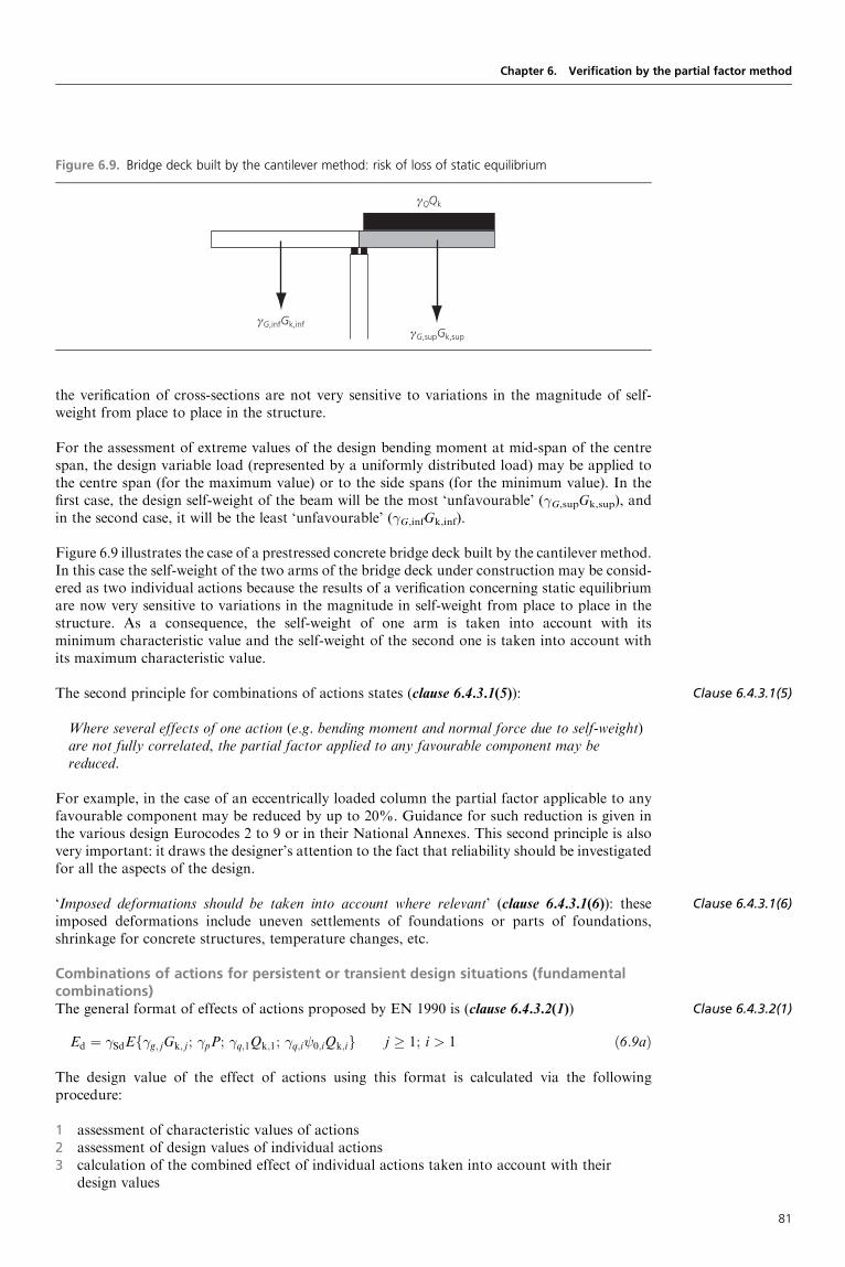
the verification of cross-sections are not very sensitive to variations in the magnitude of self-weight from place to place in the structure.
For the assessment of extreme values of the design bending moment at mid-span of the centrespan, the design variable load (represented by a uniformly distributed load) may be applied tothe centre span (for the maximum value) or to the side spans (for the minimum value). In thefirst case, the design self-weight of the beam will be the most ‘unfavourable’ (�G,supGk,sup), andin the second case, it will be the least ‘unfavourable’ (�G,infGk,inf).
Figure 6.9 illustrates the case of a prestressed concrete bridge deck built by the cantilever method.In this case the self-weight of the two arms of the bridge deck under construction may be consid-ered as two individual actions because the results of a verification concerning static equilibriumare now very sensitive to variations in the magnitude in self-weight from place to place in thestructure. As a consequence, the self-weight of one arm is taken into account with itsminimum characteristic value and the self-weight of the second one is taken into account withits maximum characteristic value.
The second principle for combinations of actions states (clause 6.4.3.1(5)):
Where several effects of one action (e.g. bending moment and normal force due to self-weight)are not fully correlated, the partial factor applied to any favourable component may bereduced.
For example, in the case of an eccentrically loaded column the partial factor applicable to anyfavourable component may be reduced by up to 20%. Guidance for such reduction is given inthe various design Eurocodes 2 to 9 or in their National Annexes. This second principle is alsovery important: it draws the designer’s attention to the fact that reliability should be investigatedfor all the aspects of the design.
‘Imposed deformations should be taken into account where relevant’ (clause 6.4.3.1(6)): theseimposed deformations include uneven settlements of foundations or parts of foundations,shrinkage for concrete structures, temperature changes, etc.
Combinations of actions for persistent or transient design situations (fundamentalcombinations)The general format of effects of actions proposed by EN 1990 is (clause 6.4.3.2(1))
Ed ¼ �SdEf�g; jGk; j ; �pP; �q;1Qk;1; �q;i 0;iQk;ig j � 1; i > 1 ð6:9aÞ
The design value of the effect of actions using this format is calculated via the followingprocedure:
1 assessment of characteristic values of actions2 assessment of design values of individual actions3 calculation of the combined effect of individual actions taken into account with their
design values
Clause 6.4.3.1(5)
Clause 6.4.3.1(6)
Clause 6.4.3.2(1)
Chapter 6. Verification by the partial factor method
Figure 6.9. Bridge deck built by the cantilever method: risk of loss of static equilibrium
γQQk
γG,supGk,sup
γG,infGk,inf
81

Clause 6.4.3.2
Clause 6.4.3.2(2)
Clause 6.4.3.2(3)
4 application of the model uncertainty factor �Sd in order to obtain the design value of theeffect of actions.
In expression (6.9a) it is assumed that a number of variable actions are acting simultaneously.Qk,1 is the leading variable action: this means that, for the effect under consideration (e.g.bending moment in a cross-section of a structural member), the variable action Q1 isapplied in order to obtain the most unfavourable effect and is therefore taken into accountwith its characteristic value Qk,1. Other variable actions should be taken into account simul-taneously, together with the leading variable action, if this is physically possible: these variableactions are called accompanying variable actions and are taken into account with theircombination value 0,iQk,i. For example, in a building structure, several variable loads can actsimultaneously: imposed loads on floors, wind, temperature, etc. The rule, based on the selectionof one particular variable action as the leading variable action of the combination of actions, isgenerally adopted in all design Eurocodes. Nevertheless, a slight deviation is allowed when usingexpressions (6.10a) and (6.10b) given in clause 6.4.3.2 as explained below. When the leadingaction is not obvious (i.e. when the most critical combination of actions cannot be identifiedeasily), it has to be understood that each variable action should be considered in turn as theleading one.
In the most common cases, temperature changes, shrinkage and uneven settlements may beconsidered as accompanying. Also, in relevant load cases, permanent actions that increase theeffect of the variable actions (i.e. produce unfavourable effects) are represented by their upperdesign values, those that decrease the effect of the variable actions (i.e. produce favourableeffects) are represented by their lower design values.
In many cases, the combination of effects of actions is directly based on the design values of allactions (clause 6.4.3.2(2)):
Ed ¼ Ef�G; jGk; j ; �PP; �Q;1Qk;1; �Q;i 0;iQk;ig j � 1; i > 1 ð6:9bÞ
The values of the � and factors for actions are given in Annex A to EN 1990 (see Chapter 7 forthe case of buildings), and the partial factors for properties of materials and products are given inthe design Eurocodes (EN 1992 to EN 1999).
Two expressions of the combination of actions in the braces in expression (6.9b) are proposed inEN 1990 (clause 6.4.3.2(3)). The most classical expression isX
j� 1
�G; jGk; j ‘+’ �PP ‘+’ �Q;1Qk;1 ‘+’Xi> 1
�Q;i 0;iQk;i ð6:10Þ
where ‘þ’ denotes ‘to be combined with’,P
denotes ‘the combined effect of ’ and P representsaction due to prestressing. In most common cases, where there is no action due to prestressing,all factors �Q,i are equal, and expression (6.10) becomes
X�G; j;supGk; j;sup ‘+’
X�G; j;infGk; j;inf ‘+’ �Q Qk;1 ‘+’
Xi> 1
0;iQk;i
� �ðD6:13Þ
However, for the STR and GEO limit states discussed earlier, EN 1990 also allows (if permittedby the National Annex) the less favourable of the two following expressions:
Xj� 1
�G; jGk; j ‘+’ �PP ‘+’ �Q;1 0;1Qk;1 ‘+’Xi> 1
�Q;i 0;iQk;i
Xj� 1
j�G; jGk; j ‘+’ �PP ‘+’ �Q;1Qk;1 ‘+’Xi> 1
�Q;i 0;iQk;i
8>>><>>>:
ð6:10aÞ
ð6:10bÞ
where is a reduction factor for unfavourable permanent actions. It is normally chosen withinthe range 0.85–1.00 (see Chapter 7). A discussion on the practical consequences of these twoexpressions can be found in Chapter 7. In expression (6.10a), all variable actions are takeninto account with their combination value ( 0Qk). In expression (6.10b), one variable action is
Designers’ Guide to Eurocode: Basis of Structural Design
82

identified as a leading action (the other variable actions are taken into account as accompanyingactions), but a reduction factor is applied to the unfavourable permanent actions. Expressions(6.10a) and (6.10b) mean that the magnitude level corresponding to characteristic values ofpermanent and variable actions is such that the probability attached to a combination ofactions where permanent unfavourable actions and the leading variable action are taken intoaccount with their characteristic value is very low. A more accurate explanation is given inChapter 7, based on reliability methods. Expressions (6.10a) and (6.10b) will always give alower design value for the load effect than the use of expression (6.10). Expression (6.10a) willbe more unfavourable when the variable action is greater than the permanent action, whileexpression (6.10b) will be more unfavourable when the permanent action is greater than thevariable action.
EN 1990 underlines that if the relationship between actions and their effects is not linear(clause 6.4.3.2(4)), expression (6.9a) or (6.9b) should be applied directly, depending upon therelative increase in the effects of actions compared with the increase in the magnitude of actions.
The choice between expressions (6.10) or (6.10a) and (6.10b) will be stated in the National Annex(see Chapter 7).
Combinations of actions for accidental design situationsThe general format of effects of actions for the accidental design situations is analogous to thegeneral format for STR/GEO ultimate limit states. Here, the leading action is the accidentalaction, and the most general expression of the design value of the effect of actions is the following(clause 6.4.3.3(1)):
Ed ¼ EfGk; j;P;Ad; ð 1;1 or 2;1ÞQk;1; 2;iQk;ig j � 1; i > 1 ð6:11aÞ
which can also be expressed as (clause 6.4.3.3(2))Xj� 1
Gk; j ‘+’ P ‘+’ Ad ‘+’ ð 1;1 or 2;1ÞQk;1 ‘+’Xi> 1
2;iQk;i ð6:11bÞ
This combination considers that:
g accidents are unintended events such as explosions, fire or vehicular impact, which are ofshort duration and have a low probability of occurrence
g a certain amount of damage is generally acceptable in the event of an accidentg accidents generally occur when structures are in use (see also Chapter 2 of this guide).
Hence, to provide a realistic accidental combination, accidental actions are applied directly; withthe frequent and quasi-permanent combination values used for the main (if any) and othervariable actions, respectively (clause 6.4.3.3(3)).
Regarding the representative value (frequent or quasi-permanent) of a possible main variableaction, discretion is left to national authorities for the reason that all accidental situations orevents cannot be similarly treated. For example, in the case of fire, it seems logical to adopt afrequent value of imposed loads in a staircase together with the design accidental action. Inother cases, the choice may be different. When the main variable action is not obvious, eachvariable action should be considered in turn as the main action.
The combinations for accidental design situations either involve an explicit design value ofaccidental action Ad (e.g. impact) or refer to a situation after an accidental event (Ad ¼ 0).For fire situations, Ad refers to the design value of the indirect thermal action as determinedby EN 1991-1-2 (clause 6.4.3.3(4)).
Combinations of actions for seismic design situationsIn the Eurocode system, seismic actions have not been amalgamated with most commonaccidental actions because differing levels of magnitude, depending upon the serviceability orsafety requirements, can be defined by a national authority or a client. For example, in the
Clause 6.4.3.2(4)
Clause 6.4.3.3(1)
Clause 6.4.3.3(2)
Clause 6.4.3.3(3)
Clause 6.4.3.3(4)
Chapter 6. Verification by the partial factor method
83

Clause 6.4.3.4(1)
Clause 6.4.3.4(2)
Clause 6.4.5
Clause 6.4.5
Clause 6.5.1(1)P
Clause 6.5.3(1)
Clause 6.5.3(2)
case of railway bridges, the appropriate authority may require continuation of normal rail traffic(including high-speed passenger trains) after an earthquake of a relatively short return period(e.g. 50 years). However, more or less limited damage may be accepted for a more severeearthquake (e.g. over 500 years return period). In any case, the general format of effects isgiven by the following expression (clause 6.4.3.4(1)):
Ed ¼ EfGk; j;P;AEd; 2;iQk;ig j � 1; i � 1 ð6:12aÞ
that can be expressed, in common cases, as (clause 6.4.3.4(2))Xj� 1
Gk; j ‘+’ P ‘+’ AEd ‘+’Xi� 1
2;iQk;i ð6:12bÞ
6.4.4 Partial factors for actions and combinations of actionsThis short clause (clause 6.4.5) reminds the designer that � and factors are found in Annex A toEN 1990 (see Chapter 7 for the case of buildings), which refers to the various parts of EN 1991and to National Annexes.
6.4.5 Partial factors for material and productsSimilarly to the previous clause, the � factors applicable to properties of materials and productsare found in the design Eurocodes 2 to 9, which may refer to National Annexes (clause 6.4.5).
6.5. Serviceability limit states6.5.1 Verifications of serviceabilityFrom a general point of view, verifications of serviceability limit states are expressed as(clause 6.5.1(1)P)
Ed�Cd (6.13)
where:Cd is the limiting design value of the relevant serviceability criterion.Ed is the design value of the effects of actions specified in the serviceability criterion,
determined on the basis of the relevant combination.
It should be mentioned that there are differences in serviceability criteria, depending on the typeof limit state and the structural material under consideration. For example, the serviceabilitycriteria may refer to deformations, to crack widths for concrete structures, or to vibrationfrequencies for sway structures, independently of their structural materials.
6.5.2 Serviceability criteriaServiceability requirements related with deformations are generally defined in the design Euro-codes 2 to 9, or for the particular project, or by the national authority, in accordance withAnnex A to EN 1990 (see Chapter 7) (clause 6.5.2(1)).
6.5.3 Combination of actionsThree categories of combinations of actions are proposed in EN 1990: characteristic, frequentand quasi-permanent. The appropriate combinations of actions should be selected dependingon the serviceability requirements and performance criteria imposed for the particular project,the client or the relevant national authority (clause 6.5.3(1)).
The characteristic combination (in the past, the wording ‘rare combination’ was also used) isexpressed as follows (clause 6.5.3(2)):
Ed ¼ EfGk; j;P;Qk;1; 0;iQk;ig j � 1; i > 1 ð6:14aÞ
or, in common cases,Xj� 1
Gk; j ‘+’ Pk ‘+’ Qk;1 ‘+’Xi> 1
0;iQk;i ð6:14bÞ
Designers’ Guide to Eurocode: Basis of Structural Design
84

This characteristic combination of actions is built on the same pattern as the fundamentalcombination of actions for STR/GEO ultimate limit states: all � factors are generally equal to1, and this is an aspect of the semi-probabilistic format of structural verifications.
The characteristic combination is normally used for irreversible limit states (e.g. the exceedanceof some cracking limits in concrete structures).
The frequent combination
Ed ¼ EfGk; j;P; 1;1Qk;1; 2;iQk;ig j � 1; i > 1 ð6:15aÞ
in which the combination of actions in braces can be expressed asXj� 1
Gk; j ‘+’ P ‘+’ 1;1Qk;1 ‘+’Xi> 1
2;iQk;i ð6:15bÞ
is normally used for reversible limit states such as the quasi-permanent combination of actions.
The quasi-permanent combination (also used for reversible limit states), which is used for theassessment of long-term effects (e.g. effects due to creep and shrinkage in concrete structures)is written as
Ed ¼ EfGk; j; P; 2;iQk;ig j � 1; i � 1 ð6:16aÞ
or (simplified)Xj� 1
Gk; j ‘+’ P ‘+’Xi� 1
2;iQk;i ð6:16bÞ
Guidance on the selection of the representative value of the prestressing action (i.e. Pk or Pm) isgiven in the design Eurocodes 1 to 9 for the type of prestressing under consideration.
Partial 6.5.4 factors for materials‘For serviceability limit states the partial factors �M for the properties of materials should be takenas 1,0 except if differently specified in EN 1992 to EN 1999’ (clause 6.5.4).
FURTHER READING
See the list at the end of Chapter 7.
Clause 6.5.4
Chapter 6. Verification by the partial factor method
85

Designers’ Guide to Eurocode: Basis of Structural DesignISBN 978-0-7277-4171-4
ICE Publishing: All rights reserved
http://dx.doi.org/10.1680/bsd.41714.087
Chapter 7
Annex A1 (normative) –Application for buildings
This chapter is concerned with the definition of combinations of actions and requirements forthe verification of building structures. The material described in this chapter is covered inAnnex A1, ‘Application for buildings’, of EN 1990. This annex, which completes Section 6 (seeChapter 6), is normative. The material described in this chapter is covered in Annex A1 ofEN 1990 as follows:
g Field of application Clause A1.1g Combinations of actions Clause A1.2g Ultimate limit states Clause A1.3g Serviceability limit states Clause A1.4
7.1. Field of applicationClause A1.1(1) states
Annex A1 gives rules and methods for establishing combinations of actions for buildings. Italso gives the recommended design values of permanent, variable and accidental actions and factors to be used in the design of buildings.
The note to clause A1.1(1) recommends that the design working life needs be defined (seeChapter 2): in general, this design working life is not normally directly used in calculations,but it has to be defined for some problems related, for example, to fatigue or corrosion of steel.
7.2. Combinations of actions7.2.1 GeneralEffects of actions that cannot exist simultaneously due to physical or functional reasons (seeChapter 6) should not be considered together in combinations of actions (clause A1.2.1(1)).This Application Rule is a matter of engineering judgement. Of course, in most cases, severalvariable actions exist simultaneously in a building: imposed loads on floors, wind actions,temperature changes, etc. The general rules applicable for the establishment of combinationsof actions are explained in Chapter 6 (see Section 6.4.3), and a comprehensive application ofthese rules may lead to a large number of load combinations. To aid simplicity for the design,EN 1990 allows (clause A1.2.1(1), note 1) the combinations of actions to be based on notmore than two variable actions.
Clause A1.1(1)
Clause A1.1(1)
Clause A1.2.1(1)
Clause A1.2.1(1)
87
BackgroundIn ENV 1991-1, ‘Basis of design’, the following simplified combinations were permitted as analternative to the fundamental combination:
Design situation with one variable action only:Xj� 1
�G; jGk; j ‘+’ ½1:5�Qk;1

Clause A1.2.1(2)
Clause A1.2.1(3)
Clause A1.2.1(1)
Clause A1.2.1(4)
Clause A1.2.2(1)
The suggested limitation to using two variable actions only is acceptable in common cases (e.g. anormal six-storey residential building) due to the high levels of characteristic and combinationvalues of variable actions and the low probability of the combined significant effects of additionalactions. Indeed, the probability of occurrence of a fundamental combination (expression (6.10))with more than two variable actions taken with their characteristic (for the leading action) andcombination (for the accompanying actions) values would be very low. Nevertheless, EN 1990draws the designer’s attention to the fact that the use of the proposed simplification maydepend on the use, the form and the location of the building. It is stressed that this simplificationmay produce unacceptable low levels of reliability when used simultaneously with expressions(6.10a) and (6.10b).
The Eurocode reminds designers what combinations of actions should be used when verifyingultimate limit states (clause A1.2.1(2)) or serviceability limit states (clause A1.2.1(3)), butmodifications of some combinations are allowed for geographical reasons in the NationalAnnex (clause A1.2.1(1), note 2).
EN 1990 does not give � factors for prestressing. These factors are defined in the relevant designEurocodes, and in particular in EN 1992 (clause A1.2.1(4)).
7.2.2 Values of factorsRecommended values of factors for the more common actions are given in Table 7.1 (whichreproduces Table A1.1 of EN 1990). They are in accordance with values givenin other parts of EN 1991, and can be altered in the National Annex. Moreover, forcountries not mentioned in the table (i.e. countries outside the EU), specific adjustments arerecommended (clause A1.2.2(1)).
Designers’ Guide to Eurocode: Basis of Structural Design
Design situation with two or more variable actions:Xj� 1
�G; jGk; j ‘+’ ½1:35�Xi� 1
Qk;i
The simplified formats have not been kept for the following reasons:
g they were not correct from a conceptual point of viewg they could not be considered as enveloping normal formats because they were not
systematically safe-sidedg they did not really lead to simpler calculations than the normal formats.
For example, if we consider a problem with one permanent action (e.g. self-weight Gk) andtwo independent variable actions (e.g. floor-imposed loads Qk,1 and wind actions Qk,2), thesimplified formats led to the consideration of the following combinations:
1.35Gkþ 1.5Qk,1
1.35Gkþ 1.5Qk,2
1.35Gkþ 1.35Qk,1þ 1.35Qk,2
In fact, the general method (based now on expression (6.10) in EN 1990) is used only forverification:
1.35Gkþ 1.5Qk,1þ 0.9Qk,2 ( 0,2¼ 0.6)
and
1.35Gkþ 1.05Qk,1þ 1.5Qk,2 ( 0,1¼ 0.7)
See Table 7.1 for factors.
88

7.3. Ultimate limit states7.3.1 Design values of actions in persistent and transient design situationsThree sets of design values of actions (sets A, B and C) are defined for persistent and transientdesign situations, depending on the limit state under consideration (clause A1.3.1(1)). Numericalvalues for � and factors are normally given in the National Annex. However, EN 1990recommends values for � and which may probably be widely adopted. These values aregiven in notes to EN 1990, and are included in Tables A1.2(A) to A1.2(C) (reproduced here asTables 7.2(A) to 7.2(C)), corresponding to sets A, B and C, respectively.
Concerning permanent actions, the reader is reminded that the use of upper and lower character-istic values (see Chapter 4) is intended for all limit states which appear to be very sensitive to
Clause A1.3.1(1)
Chapter 7. Annex A1 (normative) – Application for buildings
Table 7.1. Recommended values of factors for buildings (Reproduced from EN 1990 (Table A1.1),
with permission from BSI)
Action 0 1 2
Imposed loads in buildings, category (see EN 1991-1-1)
Category A: domestic, residential areas
Category B: office areas
Category C: congregation areas
Category D: shopping areas
Category E: storage areas
Category F: traffic area, vehicle weight� 30 kN
Category G: traffic area, 30 kN< vehicle weight� 160 kN
Category H: roofs
0.7
0.7
0.7
0.7
1.0
0.7
0.7
0
0.5
0.5
0.7
0.7
0.9
0.7
0.5
0
0.3
0.3
0.6
0.6
0.8
0.6
0.3
0
Snow loads on buildings (see EN 1991-1-3)�
Finland, Iceland, Norway, Sweden
Remainder of CEN Member States, for sites located at altitude H> 1000m a.s.l.
Remainder of CEN Member States, for sites located at altitude H� 1000m a.s.l.
0.70
0.70
0.50
0.50
0.50
0.20
0.20
0.20
0
Wind loads on buildings (see EN 1991-1-4) 0.6 0.2 0
Temperature (non-fire) in buildings (see EN 1991-1-5) 0.6 0.5 0
NOTE The values may be set by the National Annex.
(�) For countries not mentioned below, see relevant local conditions.
Table 7.2(A). Design values of actions (EQU) (set A) (Reproduced from EN 1990 (Table A1.2(A)),
with permission from BSI)
Persistent and transientdesign situations
Permanent actions Leadingvariableaction (�)
Accompanying variable actions
Unfavourable Favourable Main (if any) Others
(Eq. 6.10) �Gj,supGkj,sup �Gj,infGkj,inf �Q,1Qk,1 �Q,i 0,iQk,i
(�) Variable actions are those considered in Table A1.1
NOTE 1 The � values may be set by the National Annex. The recommended set of values for � are:
�Gj,sup¼ 1.10
�Gj,inf¼0.90
�Q,1¼1.50 where unfavourable (0 where favourable)
�Q,i¼1.50 where unfavourable (0 where favourable)
NOTE 2 In cases where the verification of static equilibrium also involves the resistance of structural members, asan alternative to two separate verifications based on Tables A1.2(A) and A1.2(B), a combined verification, based onTable A1.2(A), may be adopted, if allowed by the National annex, with the following set of recommended values.The recommended values may be altered by the National annex.
�Gj,sup¼ 1.35
�Gj,inf¼1.15
�Q,1¼1.50 where unfavourable (0 where favourable)
�Q,i¼1.50 where unfavourable (0 where favourable)
provided that applying �Gj,inf¼1.00 both to the favourable part and to the unfavourable part of permanent actionsdoes not give a more unfavourable effect.
89

Desig
ners’
Guideto
Euroco
de:Basis
ofStru
cturalDesig
n
Table 7.2(B). Design values of actions (STR/GEO) (set B) (Reproduced from EN 1990 (Table A1.2(B)), with permission from BSI)
Persistent andtransient designsituations
Permanent actions Leadingvariableaction (�)
Accompanying variableactions (�)
Persistent andtransient designsituations
Permanent actions Leadingvariableaction (�)
Accompanying variableactions (�)
Unfavourable Favourable Main (if any) Others Unfavourable Favourable Action Main Others
(Eq. 6.10) �Gj,supGkj,sup �Gj,infGkj,inf �Q,1Qk,1 �Q,i 0,iQk,i (Eq. 6.10a) �Gj,supGkj,sup �Gj,infGkj,inf �Q,1 0,1Qk,1 �Q,i 0,iQk,i
(Eq. 6.10b) �Gj,supGkj,sup �Gj,infGkj,inf �Q,1Qk,1 �Q,i 0,iQk,i
(�) Variable actions are those considered in Table A1.1
NOTE 1 The choice between 6.10, or 6.10a and 6.10b will be in the National Annex. In case of 6.10a and 6.10b, the National Annex may in addition modify 6.10a to include permanent actions only.
NOTE 2 The � and values may be set by the National annex. The following values for � and are recommended when using expressions 6.10, or 6.10a and 6.10b.
�Gj,sup¼1.35
�Gj,inf¼ 1.00
�Q,1¼1.50 where unfavourable (0 where favourable)
�Q,i¼1.50 where unfavourable (0 where favourable)
¼0.85 (so that �Gj,sup¼0.85� 1.35 1.15). (N.B. ¼0.925 in the BSI National Annex)
See also EN 1991 to EN 1999 for � values to be used for imposed deformations.
NOTE 3 The characteristic values of all permanent actions from one source are multiplied by �G,sup if the total resulting action effect is unfavourable and �G,inf if the total resulting action effect isfavourable. For example, all actions originating from the self weight of the structure may be considered as coming from one source; this also applies if different materials are involved.
NOTE 4 For particular verifications, the values for �G and �Q may be subdivided into �g and �q and the model uncertainty factor �Sd. A value of �Sd in the range 1.05 to 1.15 can be used in mostcommon cases and can be modified in the National Annex.
90

variations in magnitude of these actions (clause A1.3.1(2)). Of course, some engineering judge-ment is necessary to recognise the cases where a limit state is very or not very sensitive to suchvariations. This rule is intended mainly for limit states of static equilibrium (EQU).
As explained in Chapter 6, four limit states are identified, depending on the way to introducereliability in the assessment of geotechnical and non-geotechnical actions and in geotechnicalresistances: EQU, STR, GEO and FAT.
The correspondence between limit states and sets of design values is shown in Table 7.3 (clausesA1.3.1(3) and A1.3.1(4)).
For GEO limit states or STR limit states involving geotechnical actions, three approaches aredefined (clause A1.3.1(5)), and sets of design values are given for each approach in EN 1990.(EN 1997 also introduces the limit states UPL (loss of equilibrium of the structure or theground due to uplift by water pressure) and HYD (hydraulic heave, internal erosion andpiping in the ground caused by hydraulic gradients).)
These limit states (EQU, STR and GEO) are schematically illustrated in Figure 7.1.
The choice of approach 1, 2 or 3 is made by the appropriate National Annex. EN 1990 does notgive any design value for limit states due to fatigue (FAT) or for limit states associated with puregeotechnical, hydraulic or buoyancy failure (clauses A1.3.1(6) and A1.3.1(7)), which are treatedin EN 1997, ‘Geotechnical design’, and the Designers’ Guide in this series for EN 1997.
7.3.2 EQU limit statesThe static equilibrium of a structure or of any part of it (considered as a rigid body) is verifiedusing the design values of actions in Table 7.2(A) (set A), which reproduces Table A1.2(A) ofEN 1990.
Clause A1.3.1(2)
Clause A1.3.1(3)
Clause A1.3.1(4)
Clause A1.3.1(5)
Clause A1.3.1(6)
Clause A1.3.1(7)
Chapter 7. Annex A1 (normative) – Application for buildings
Table 7.2(C). Design values of actions (STR/GEO) (set C) (Reproduced from EN 1990 (Table A1.2(C)),
with permission from BSI)
Persistent and transientdesign situations
Permanent actions Leadingvariableaction (�)
Accompanying variable actions (�)
Unfavourable Favourable Main (if any) Others
(Eq. 6.10) �Gj,supGkj,sup �Gj,infGkj,inf �Q,1Qk,1 �Q,i 0,iQk,i
(�) Variable actions are those considered in Table A1.1
NOTE The � values may be set by the National annex. The recommended set of values for � are:
�Gj,sup¼ 1.00
�Gj,inf¼1.00
�Q,1¼1.30 where unfavourable (0 where favourable)
�Q,i¼1.30 where unfavourable (0 where favourable)
Table 7.3. Limit states and sets of design values
Limit state Set of partial factors
EQU – static equilibrium Set A (Table 7.3(a))
STR – resistance of building structures not
involving geotechnical actions
Set B (Table 7.3(b))
STR – resistance of building structures involving
geotechnical actions
GEO – failure or excessive deformation of the
ground
Approach 1
Set C (Table 7.3(c)) for all actions, and set B for all
actions, the most unfavourable
Approach 2
Set B for all actions
Approach 3
Set B for actions on/from the structure, and set C
for geotechnical actions
91

Clause 6.4.3.1
Clause A1.3
As can be seen from Table 7.2(A), the combination of actions is based on expression (6.10) ofEN 1990, with one leading variable action, accompanying variable actions and permanentactions which may be ‘unfavourable’ if they act together with the variable actions, or ‘favourable’if they act opposite to the variable actions.
As already explained, EN 1990 gives only recommended values for � factors in notes 1 and 2 toTable A1.2(A): these � factors may be confirmed or altered by the National Annex.
The numerical � values recommended in Table A1.1(A) need explanation. With the set ofrecommended � values given in note 1, the combination of actions reads
1:10X
Gk; j;sup ‘+’ 0:90X
Gk; j;inf ‘+’ 1:50Qk;1 ‘+’ 1:50Xi� 2
0;iQk;i
or, in a more ‘user-friendly’ way,
1:10Gunfav ‘+’ 0:90Gfav ‘+’ 1:50Qk;1 ‘+’ 1:50Xi� 2
0;iQk;i
The identification of favourable and unfavourable permanent actions is based on the two rulesevoked previously: ‘where the results of a verification are very sensitive to variations of the magni-tude of a permanent action from place to place in a structure, the unfavourable and the favourableparts of this action shall be considered as individual actions’ (clause 6.4.3.1) and the rule concerningthe use of the upper and lower characteristic values of permanent actions (as explained inChapter 4). In many cases, nominal values are taken as characteristic values.
Where static equilibrium is not directly ensured, a stabilising system is normally provided. Forsuch a case, a verification with respect to ultimate limit states STR/GEO is necessary. In thatcase, an alternative set of recommended values is given which may be used, if allowed by theNational Annex, to verify both relevant EQU and STR limit states.
With the set of recommended values given in note 2 of Table A1.2(A) of clause A1.3 of EN 1990,the combination of actions is
1:35X
Gk; j;sup ‘+’ 1:15X
Gk; j;inf ‘+’ 1:50Qk;1 ‘+’ 1:50Xi� 2
0;iQk;i
or, in a more ‘user-friendly’ way,
1:35Gunfav ‘+’ 1:15Gfav ‘+’ 1:50Qk;1 ‘+’ 1:50Xi� 2
0;iQk;i
Designers’ Guide to Eurocode: Basis of Structural Design
Figure 7.1. Examples of limit states EQU, STR and GEO
STR
EQU
Approaches 1 23
STR
STR
STR
STR involvinggeotechnical actions
GEO
GEO
92

There is no scientific interpretation of the proposed set of design values: they have beenadjusted in order to give an acceptable combination to be used both for EQU and STRultimate limit states. A detailed example explaining EQU is developed later in this chapter, inSection 7.5.1.
BackgroundThe partial factors 1.10 and 0.90 may be interpreted in the following way. In accordance withreliability methods, where permanent actions are unfavourable, their design value derivesfrom the formula
Gd;sup ¼ Gmð1� �E�VGÞ ¼ Gmð1þ 0:7� 3:8� VGÞ
Where permanent actions are favourable, they may be treated as resistances, and their designvalue derives from the formula
Gd;inf ¼ Gmð1� �R�VGÞ ¼ Gmð1� 0:8� 3:8� VGÞ
VG is the coefficient of variation of the permanent action under consideration. In EN 1990,note 2 of clause 4.1.2(1)P (see Chapter 4) suggests that the coefficient of variation ofpermanent actions can be in the range 0.05–0.10. These values apply more to the effectsof permanent actions (including model uncertainties) than to the actions themselves (forwhich there is no model uncertainty). In static equilibrium problems (EQU), the permanentactions are represented directly (and not as effects of actions) in the expression of the limitstate, and these actions are mainly due to self-weight. This explains why a lower range can beadopted for VG, such as 0.02–0.05 (0.02 corresponds to bridge construction sites with high-level control). For example, for VG¼ 0.05, Gd,sup¼ 1.13Gm and Gd,inf¼ 0.85Gm, which givesan interpretation of the recommended partial factors.
It should also be noted that the set of partial factors recommended in note 1 of Table A1.2(A)of EN 1990 is inconsistent because factors 1.10 and 0.9 do not include any model uncertaintyfactor whereas the factor 1.50 for variable actions includes a model uncertainty factor;however, this has no real importance in most cases.
7.3.3 STR limit statesThe design of structural members not involving geotechnical actions is normally verified usingthe design values of actions from set B (Table 7.2(B) (Table A1.2(B) in EN 1990)).
The presentation of Table A1.2(B) of EN 1990 may appear somewhat elaborate, and needs adetailed explanation.
First, it should be noted that Table A1.2(B) actually proposes the following three different sets ofdesign values (the decision of which one to use is left to the National Annex):
g expression (6.10)g the less favourable of expressions (6.10a) and (6.10b)g the less favourable of expressions (6.10a) ‘modified’ and (6.10b).
Expression (6.10a) ‘modified’ is the combination of actions which includes the permanent actionsshown below:
X�G;j;supGk; j;sup ‘+’
X�G;j;infGk; j;inf
Using the set of recommended values given in note 2 of Table A1.2(B), the combinations ofactions read
1:35X
Gk; j;sup ‘+’X
Gk; j;inf ‘+’ 1:50Qk;1 ‘+’ 1:50Xi� 2
0;iQk;i
Chapter 7. Annex A1 (normative) – Application for buildings
93

for expression (6.10), and
1:35X
Gk; j;sup ‘+’X
Gk; j;inf ‘+’ 1:50Xi� 1
0;iQk;i
1:15X
Gk; j;sup ‘+’X
Gk; j;inf ‘+’ 1:50Qk;1 ‘+’ 1:50Xi� 2
0;iQk;i
for expressions (6.10a) and (6.10b), respectively.
It should be noted that EN 1990 does not give recommended values for expression (6.10a)‘modified’.
It is clear that the two possibilities of expression (6.10) or expressions (6.10a) and (6.10b) are notequivalent, in that they do not lead to the same reliability level.
When using appropriate statistical data for permanent and variable actions for determining the �and 0 values, these values would be functions of the ratio between permanent and variableactions. A good approximation to these functions would result from the use of the two combina-tion expressions (expressions (6.10a) and (6.10b)) which allow each action including the perma-nent actions G to be either a ‘leading’ action �FFk or an accompanying action �F 0Fk. Expression(6.10) presumes that the permanent actions �GG and one variable action �QQk,1 should alwaysact together as design values.
Designers’ Guide to Eurocode: Basis of Structural Design
Background – interpretation of recommended values of � factorsThe traditional interpretation of the recommended numerical values of � factors is given inCEB Bulletins 127 and 128, �F¼ �Sd�f follows:
Action �f �Sd �F
Permanent unfavourable 1.125 1.20 1.35
Permanent favourable 0.875 1.20 1.00
Variable (unfavourable) 1.35 1.10 1.50
This interpretation is the result of very accurate studies. It shows that a unique value of a �Sdfactor has no scientific justification, and results from engineering judgement.
Background – reliability levels attached to the three proceduresThe three alternative procedures for combinations of actions provided in Annex A1 ofEN 1990 have been investigated and also compared with combination rules given inBritish standards (BS 5950 and BS 8110) by using probability-based reliability methods.
In order to characterise the differences resulting from the three procedures, an elementarymodel was used, based on the following limit state function:
g(X)¼ �RR� �E(GþQþW)
where (X) denotes the vector of basic variables (random variables entering the right-handside of this equation), �R denotes the factor expressing the uncertainty of the resistancemodel, �E denotes the factor expressing the uncertainty of the loading model, R denotes aresistance, G denotes a permanent action, Q denotes imposed loads on building floors (asdefined in EN 1990) and W denotes wind action.
Appropriate probabilistic models have been selected for the six basic variables. Parametersconcerning the resistance of reinforced concrete (in particular the mean and standarddeviation) have been determined by considering the bending resistance of a reinforced
94
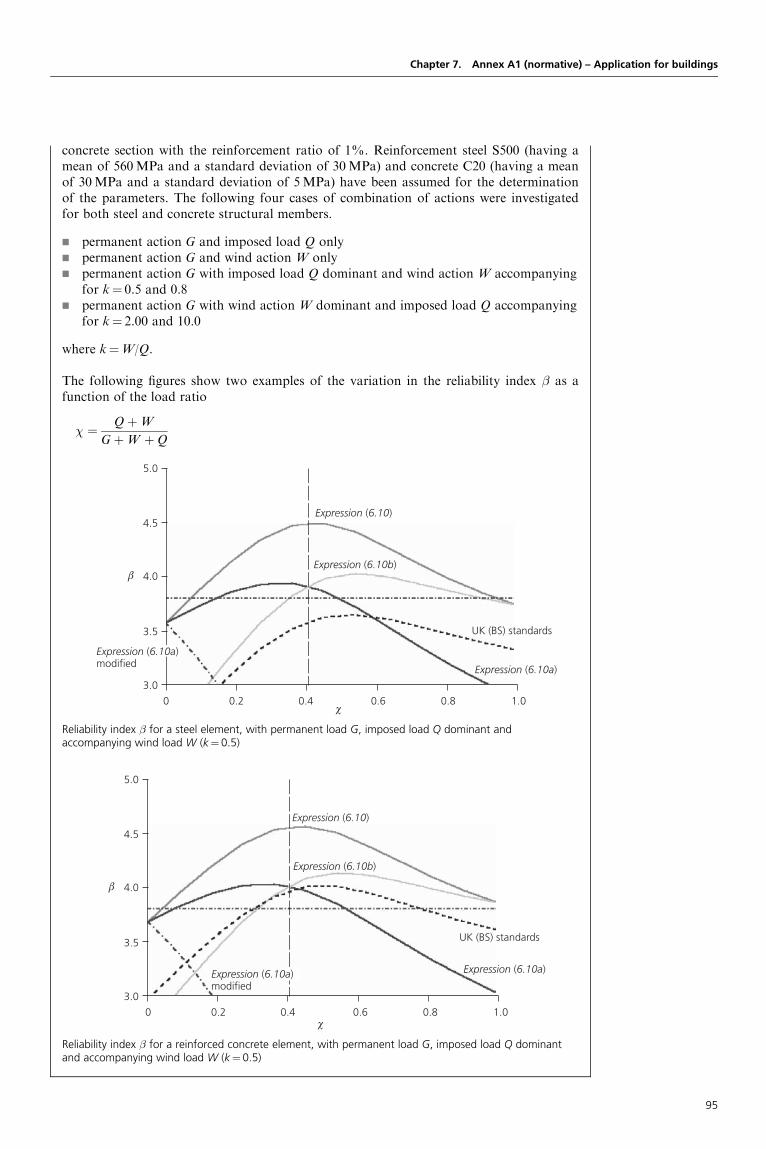
Chapter 7. Annex A1 (normative) – Application for buildings
concrete section with the reinforcement ratio of 1%. Reinforcement steel S500 (having amean of 560MPa and a standard deviation of 30MPa) and concrete C20 (having a meanof 30MPa and a standard deviation of 5MPa) have been assumed for the determinationof the parameters. The following four cases of combination of actions were investigatedfor both steel and concrete structural members.
g permanent action G and imposed load Q onlyg permanent action G and wind action W onlyg permanent action G with imposed load Q dominant and wind action W accompanying
for k¼ 0.5 and 0.8g permanent action G with wind action W dominant and imposed load Q accompanying
for k¼ 2.00 and 10.0
where k¼W/Q.
The following figures show two examples of the variation in the reliability index � as afunction of the load ratio
� ¼ QþW
GþW þQ
5.0
4.5
4.0
3.5
3.0
0 0.2 0.4 0.6 0.8 1.0
Expression (6.10)
UK (BS) standards
Expression (6.10b)
Expression (6.10a)
Expression (6.10a)modified
χ
β
Reliability index � for a steel element, with permanent load G, imposed load Q dominant andaccompanying wind load W (k¼ 0.5)
5.0
4.5
4.0
3.5
3.0
0 0.2 0.4 0.6 0.8 1.0
Expression (6.10)
UK (BS) standards
Expression (6.10b)
Expression (6.10a)Expression (6.10a)modified
χ
β
Reliability index � for a reinforced concrete element, with permanent load G, imposed load Q dominantand accompanying wind load W (k¼ 0.5)
95

In general, expression (6.10a) will be the more unfavourable than (6.10b) when the variable actionis greater than the permanent action, while expression (6.10b) will be more unfavourable thanexpression (6.10a) when the permanent action is greater than the variable action. As anexample, it can be easily shown that, for thick concrete slabs, expression (6.10a) is decisive,while, for very thin concrete slabs and steel and timber beams, expression (6.10b) is decisive.
Hence, the joint combination rules given by expressions (6.10a) and (6.10b) on one side and thatgiven by expression (6.10) on the other differ in the estimation of different risks from permanentactions (realistic persistent actions) and variable actions (assessed from extreme value distribu-tions), and represent different levels of reliability that are offered to regulatory bodies forchoice, through the National Annex as EN 1990 does not recommend a unique approach.
Attention is drawn to note 4 of Table A1.2(B), which allows identification of a model factor. Allstructural analyses are based on models (structural models and models of actions) which are onlyapproximations. This has been clearly stated in the Basic Notes on Model Uncertainties, adoptedby the CEB (Euro-International Concrete Committee, 1985).
It is clear that it is not possible to define an exact unique value for factor �Sd intended to coverindividually all structural analysis uncertainties: the value would be very different from onestructure to another, and even from one structural member cross-section to another. For thisreason, EN 1990 proposes a value of �Sd within the range 1.05–1.15 that can be used for mostcommon cases and can be modified in the National Annex. This approach can be adoptedwhen considering non-linear problems. In many cases, the value of 1.15 is the most appropriate.
The use of expression (6.10) is, perhaps, economically less favourable than the use of expressions(6.10a) and (6.10b), but, in the case of concrete structures, its use may cover several of theserviceability limit states.
7.3.4 STR/GEO limit statesResistance of structural members (footings, piles, basement walls, etc.) involving geotechnicalactions and the resistance of the ground should be verified using one of the three approaches(to be chosen in the National Annex) in Table 7.3:
g Approach 1: applying in separate calculations design values from Table 7.2(C) (TableA1.2(C) of EN 1990) and Table 7.2(B) (Table A1.2(B) of EN 1990) to the geotechnicalactions as well as the other actions on/from the structure.
g Approach 2: applying design values from Table 7.2(B) (Table A1.2(B) of EN 1990) to thegeotechnical actions as well as the other actions on/from the structure.
g Approach 3: applying design values from Table 7.2(C) (Table A1.2(C) of EN 1990) to thegeotechnical actions and, simultaneously, applying partial factors from Table 7.2(B) to theother actions on/from the structure.
Designers’ Guide to Eurocode: Basis of Structural Design
The calculations show that:
g Expression (6.10), when used with the partial factors recommended by EN 1990, givesfor most practical cases of load ratio � reliability levels above those desired (�¼ 3.8).The use of expressions (6.10a) and (6.10b) gives lower reliability levels than obtainedwith expression (6.10), but still in most cases above those desired (�¼ 3.8).
g Modified expression (6.10a) used together with expression (6.10b) from EN 1990 leadsto a lower reliability level than desired (�¼ 3.8), particularly when the load ratio � isless than 0.5.
g The combination rules in BS 5950 and BS 8110 lead to similar results as obtained withexpression (6.10) from EN 1990, when considering one variable action only. However,the use of the UK combination rules when two variable actions are being consideredtogether leads to a substantially lower reliability than EN 1990 expression (6.10) orexpressions (6.10a) and (6.10b), in particular for low load ratios �.
g The use of expression (6.10a) used together with expression (6.10b) leads to a moreuniform distribution of �, as the function of the load ratio �, than expression (6.10).
96

The three design approaches differ in the way in which they distribute partial factors betweenactions, the effects of actions, material properties and resistances. EN 1997, ‘GeotechnicalDesign’, states that this is in part due to the differing approaches in the way in which allowanceis made for uncertainties in modelling the effects of actions and resistances.
Let us consider a very basic example. Figure 7.2 shows a cantilever retaining wall with a hori-zontal backfill. The active earth pressure may be calculated on the virtual back of the wallfrom Rankine’s theory, assuming that this pressure is horizontal. No surcharge is applied tothe backfill. At depth x, the pressure is
q(x)¼ ka�k,soilx
and
ka ¼ tan2
4� ’0
k
2
� �
where ’0k is the characteristic value of the angle of shearing resistance of the backfill, �k,soil is the
characteristic value of the backfill density and ka is the coefficient of active earth pressure. Theresulting assumed horizontal force F is
F ¼ 12ka�k; soilH
2
In this formula, F is a function of ’0k and �k,soil: F¼F(�k,soil, ’
0k).
The following describes the application of partial factors to the resulting force F, in order toobtain its design value.
In the first case, a �F global factor is applied as for other permanent actions, ka being assessedfrom the characteristic value of the angle of shearing resistance ’0
k and the characteristic valueof ground density �k,soil: Fd¼ �FF(�k,soil, ’
0k).
In the second case, a �’ factor is directly applied to the shearing resistance. Thus, the design valueof the angle of shearing resistance is
’0d ¼ tan�1 tan’0
k
�’
� �
and
Fd¼F(�k,soil, ’0d)
Chapter 7. Annex A1 (normative) – Application for buildings
Figure 7.2. Example of geotechnical action
x
F
H
ka γk,soilH
γk, soil = 19 kN/m3
ϕ′k = 35º
97
The numerical comparison is established as follows. In the first case, taking �’¼ 1.25 and’0k¼ 358,
ka ¼ tan2
4� ’0
k
2
� �¼ 0:27
If F is ‘unfavourable’ regarding the limit state under consideration, and if the same � factor isapplied as for other permanent actions (1.35), then 1.35ka¼ 0.37.
In the second case, ’0d¼ 29.38, and thus ka¼ 0.34.
The two methods are not equivalent, but, in this case, lead to comparable results.
The three design approaches can now be explained.
Design approach 1In the first approach, partial factors from set B (Table 7.2(B)) are applied to both structural andgeotechnical actions. No partial material factors are applied to the geotechnical parameters. Nopartial factors are applied to the calculation of geotechnical resistance with the exception of pilefoundation design where some partial resistance factors are applied in specific cases.
In the second calculation, partial factors from set C (Table 7.2(C)) are applied in the majority ofgeotechnical cases. In this set, the structural and geotechnical actions are unfactored except forthe case of variable unfavourable actions. Partial material factors are applied to the characteristicvalues of geotechnical parameters. This set follows a material factor approach.
In the case of piles and anchors, particular partial factors are applied for the second calculation:the actions are unfactored and partial factors are applied to resistances, which are derived usingunfactored geotechnical properties.
This set follows a resistance factor approach. EN 1997 states that for the calculation ofdesign values giving rise to unfavourable actions on the pile and where the strength of theground is involved in other ways, such as developing negative skin friction or resisting lateralloading, partial material factors will be applied together with partial resistance factors whereappropriate.
Design approach 2This is a resistance factor approach where partial factors from set B (Table 7.2(B)) are applied tothe representative values of structural actions and/or action effects and to the characteristicvalues of geotechnical actions and/or action effects as well as to the characteristic values ofthe resistance of the ground. No material factors are applied to characteristic geotechnicalparameters.
Design approach 3This is a combined resistance factor/material factor approach where:
g partial factors from set B (Table 7.2(B)) are applied to the representative values ofstructural actions and/or action effects
g partial factors from set C (Table 7.2(C)) are applied to the representative values ofgeotechnical actions
g partial material factors are applied to characteristic geotechnical parameters, which arethen used in the derivation of the geotechnical actions/action effects as well as the groundresistance.
7.3.5 SynthesisConsidering the various sets of recommended values, it is possible to establish Table 7.4, whichproposes a synthesis of the various recommended partial factors for actions. The alternativeexpression, expression (6.10a) ‘modified’, has not been incorporated in this table because thevalues recommended by the Eurocode are not relevant for this expression.
Designers’ Guide to Eurocode: Basis of Structural Design
98
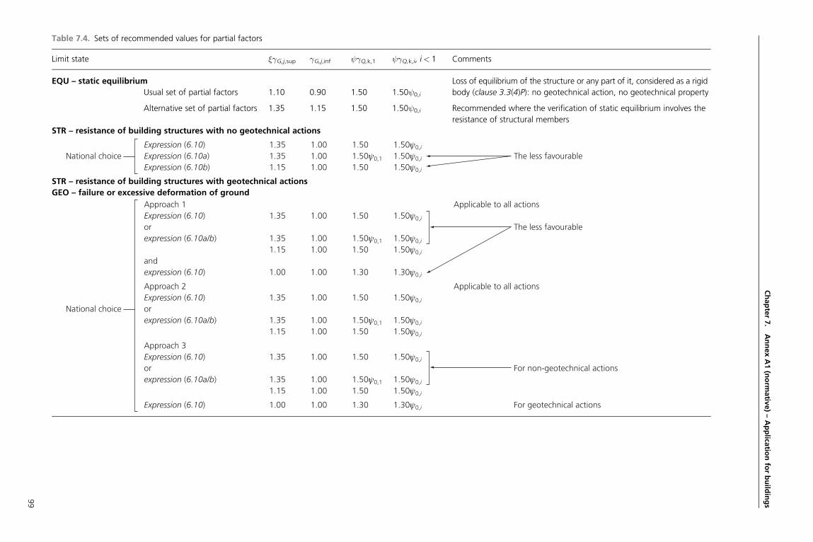
Chapter7.
AnnexA1(norm
ativ
e)–Applica
tionforbuild
ings
Table 7.4. Sets of recommended values for partial factors
Limit state �G,j,sup �G,j,inf �Q,k,1 �Q,k,i, i< 1 Comments
EQU – static equilibrium Loss of equilibrium of the structure or any part of it, considered as a rigid
Usual set of partial factors 1.10 0.90 1.50 1.50 0,i body (clause 3.3(4)P): no geotechnical action, no geotechnical property
Alternative set of partial factors 1.35 1.15 1.50 1.50 0,i Recommended where the verification of static equilibrium involves the
resistance of structural members
STR – resistance of building structures with no geotechnical actions
Expression (6.10) 1.35 1.00 1.50 1.50ψ0,i
National choice Expression (6.10a) 1.35 1.00 1.50ψ0,1 1.50ψ0,i The less favourableExpression (6.10b) 1.15 1.00 1.50 1.50ψ0,i
STR – resistance of building structures with geotechnical actions
GEO – failure or excessive deformation of ground
Approach 1 Applicable to all actionsExpression (6.10) 1.35 1.00 1.50 1.50ψ0,i
or The less favourableexpression (6.10a/b) 1.35 1.00 1.50ψ0,1 1.50ψ0,i
1.15 1.00 1.50 1.50ψ0,i
andexpression (6.10) 1.00 1.00 1.30 1.30ψ0,i
Approach 2 Applicable to all actionsExpression (6.10) 1.35 1.00 1.50 1.50ψ0,i
National choice orexpression (6.10a/b) 1.35 1.00 1.50ψ0,1 1.50ψ0,i
1.15 1.00 1.50 1.50ψ0,i
Approach 3Expression (6.10) 1.35 1.00 1.50 1.50ψ0,i
or For non-geotechnical actionsexpression (6.10a/b) 1.35 1.00 1.50ψ0,1 1.50ψ0,i
1.15 1.00 1.50 1.50ψ0,i
Expression (6.10) 1.00 1.00 1.30 1.30ψ0,i For geotechnical actions
99

Clause A1.3.2
7.3.6 Design values of actions in the accidental and seismic design situationsIn general, accidental actions are characterised by a very low probability of occurrence during thelifetime of the structure. As far as they are man-made they result from abnormal conditions of use(e.g. explosions, impact from vehicles or ships, or fire) and often are of short duration. Accidentalactions may also arise from extremely rare natural or climatic phenomena such as earthquakes,tornadoes or heavy snowfalls.
Due to the character of accidental situations their application belongs to the general safetyscenario and depends on the probability of occurrence, the importance of the building andfailure consequences. Their use is therefore decided by the regulatory bodies.
The partial factors for actions for the ultimate limit states in the accidental and seismic designsituations (expressions (6.11a) to (6.12b)) are normally taken equal to 1.0 but, in general, notonly are the reliability elements for actions modified for accidental load combinations but soalso are the partial factors for resistances.
Seismic actions are singled out because of their different treatment as accidental actions or‘normal’ actions according to the ‘seismic climate’ in various seismic regions, where thereturn period of seismic events differs significantly (e.g. differences in Central Europe or in theMediterranean area).
The combinations of actions are described in Table 7.5 (reproducing Table A1.3 in clause A1.3.2of EN 1990).
A degree of damage is generally acceptable in the event of an accident; and accidents generallyoccur when structures are in use. Hence, to provide a realistic accidental load combination, acci-dental loads are applied directly with the frequent and quasi-permanent combination values usedfor the main and other variable actions, respectively.
The combinations for accidental design situations either involve an explicit design value ofaccidental action Ad (e.g. impact) or refer to a situation after an accidental event (Ad¼ 0). Forfire situations, Ad refers to the design value of the indirect thermal action as determined inEN 1991-1-2.
For the main accompanying variable action, the National Annex should be followed as towhether to use the frequent or the quasi-permanent value. This rule is mainly intended for firedesign situations: it is easy to understand that, in the case of a fire, crowding of people, forexample, on staircases, is normally foreseeable and that the use in calculations of the quasi-permanent value of imposed loads on floors may give an unacceptable level of reliability.
Seismic design situations are analogous to accidental design situations, but increasinglyfrequently, for example, for the design of railway bridges, two levels of seismic action aretaken into account, corresponding to different return periods: one related to ultimate limitstate verifications and the other related to serviceability limit states concerned with specificcomfort criteria for passengers.
Designers’ Guide to Eurocode: Basis of Structural Design
Table 7.5. Design values of actions for use in accidental and seismic combinations of actions
(Reproduced from EN 1990 (Table A1.3), with permission from BSI)
Design situation Permanent actions Leadingaccidentalor seismicaction
Accompanying variableactions (��)
Unfavourable Favourable Main (if any) Others
Accidental (�) (Eq. 6.11a/b) Gkj,sup Gkj,inf Ad 11 or 21Qk1 2,i Qk,i
Seismic (Eq. 6.12a/b) Gkj,sup Gkj,inf �IAEk or AEd 2,i Qk,i
(�) In the case of accidental design situations, the main variable action may be taken with its frequent or, as inseismic combinations of actions, its quasi-permanent values. The choice will be in the National annex, depending onthe accidental action under consideration. See also EN 1991-1-2.
(��) Variable actions are those considered in Table 7.1 (Table A1.1 of EN 1990).
100

7.3.7 FatigueFatigue is not treated in Annex A1 to EN 1990. All rules relating to fatigue problems are given inthe design Eurocodes 2 to 9. For fatigue assessments the partial factors are dependent on whetherprewarning mechanisms exist or not, so that damage preceding failure can be detected andpreventive measures undertaken.
If sufficient prewarning signals can be detected under normal conditions of use the structure isclassified as damage-tolerant, otherwise the structure is classified as not damage-tolerant.
For damage-tolerant structures the partial factors on actions for the fatigue assessment may betaken as �F¼ 1.00. The structure may be fully used even when the design fatigue life is exceeded,as long as no prewarning signals are observed.
When the structure is not damage-tolerant the partial factors to be applied depend on whetherthe loading is monitored or not.
In the case of a monitored load, the partial factor to be applied to the fatigue damage should be atleast 1.35, and the structure should also be taken out of service when the cumulative fatiguedamage reaches its limit when no prewarning signals are apparent. In the case of a non-monitored load, the partial factor should be at least 2.00, and the structure should be takenout of service when the calculated service life (e.g. 50 years) is exceeded.
Methods for the determination of damage tolerance and notes on how inspection and controlmeasures influence the partial factor are given in EN 1992 to EN 1999.
7.4. Serviceability limit states7.4.1 Partial factors for actionsFor serviceability limit states the partial factors for actions are normally taken as 1.0: this aspectis a main feature of the semi-probabilistic format. In some cases, different values may be definedin the design Eurocodes 1 to 9. In EN 1990, the serviceability combinations of actions arepresented in Table A1.4 (reproduced here as Table 7.6).
The combinations given in Table 7.6 can be written as follows:
g characteristic combination,XGk; j;sup ‘+’
XGk; j;inf ‘+’Qk;1 ‘+’
Xi> 1
0;iQk;i
g frequent combination,XGk; j;sup ‘+’
XGk; j;inf ‘+’ 1;1Qk;1 ‘+’
Xi> 1
2;iQk;i
g quasi-permanent combination,XGk; j;sup ‘+’
XGk; j;inf ‘+’ 2;1Qk;1 ‘+’
Xi> 1
2;iQk;i
7.4.2 Serviceability criteriaServiceability criteria for buildings as for other civil engineering works are not always easy todefine because they are dependent upon requirements which are partly subjective: floor stiffness,
Chapter 7. Annex A1 (normative) – Application for buildings
Table 7.6. Design values of actions for use in the combination of actions (Reproduced from EN 1990
(Table A1.4), with permission from BSI)
Combination Permanent actions Gd Variable actions Qd
Unfavourable Favourable Leading Others
Characteristic
Frequent
Quasi-permanent
Gkj,sup
Gkj,sup
Gkj,sup
Gkj,inf
Gkj,inf
Gkj,inf
Qk,1
1,1Qk,1
2,1Qk,1
0,iQk,i
2,iQk,i
2,iQk,i
101

Clause A1.4.2(1)
Clause A1.4.2(2)
Clause A1.4.2(3)P
Clause A1.4.3(2)
differential floor levels, storey sway and/or building sway and roof stiffness. Stiffness criteria maybe expressed in terms of limits for vertical deflections and for vibrations, or in terms of limits forhorizontal displacements (clause A1.4.2(1)).
The Eurocode does not provide numerical serviceability criteria, but indicates that these shouldbe agreed with the client for a particular project and may be defined in the National Annex(clause A1.4.2(2)). The main reason for this is that serviceability criteria are normally expressedin terms of deflections or displacements and should be defined independently of the structuralmaterials. However, it has not yet been possible to harmonise among all materials.
No further comments are necessary for clause A1.4.2(3)P.
7.4.3 Deformations and horizontal displacementsTables 7.7 and 7.8 give some examples of limiting values of vertical and horizontal deflectionswith the notation defined in Figure 7.3. Note that EN 1990 gives definitions correspondingonly to Figures 7.3(a) and 7.3(b) (clause A1.4.3(2)).
Designers’ Guide to Eurocode: Basis of Structural Design
Table 7.7. Examples of limiting values of vertical deflections
Serviceability requirement Combination of actions
Characteristic
combination
Frequent
combination
Quasi-permanent
combination
Deflection (see Figure 7.3): wtot wmax wmax � wmax wz
Function of the structure
Irreversible limit states (limit deformations to control cracking of particular elements)
Elements supporting bearing walls
without reinforcement
�L/300 – – – – �L/300
Elements supporting partition walls
Brittle (not reinforced)
Reinforced
Removable
�L/500
�L/300
�L/300
–
–
–
–
–
–
–
–
–
–
–
–
�L/300
�L/300
�L/150
Ceilings
Plastered
False
�L/250
�L/250
–
–
–
–
–
–
–
–
–
–
Flooring
Rigid (e.g. ceramic tiles)
Flexible (e.g. vinyl floor covering)
�L/500
�L/250
–
–
–
–
–
–
–
–
–
–
Irreversible limit states (limit deflection to ensure drainage of water)
Roof covering
Rigid
Flexible
�L/250
�L/125
–
–
–
–
–
–
–
–
–
–
Drainage slope of roof element
(Figure 7.3(c))
– – – �2% – –
Reversible limit states (Limit deformations for functioning)
Fit for use for wheeled furniture or
equipment
– – �L/300 – – –
Fit for use for overhead cranes on
tracks
– – �L/600
�25mm
– – –
Appearance of the structure
Reversible limit states (limit deformations for appearance)
�L/300
102
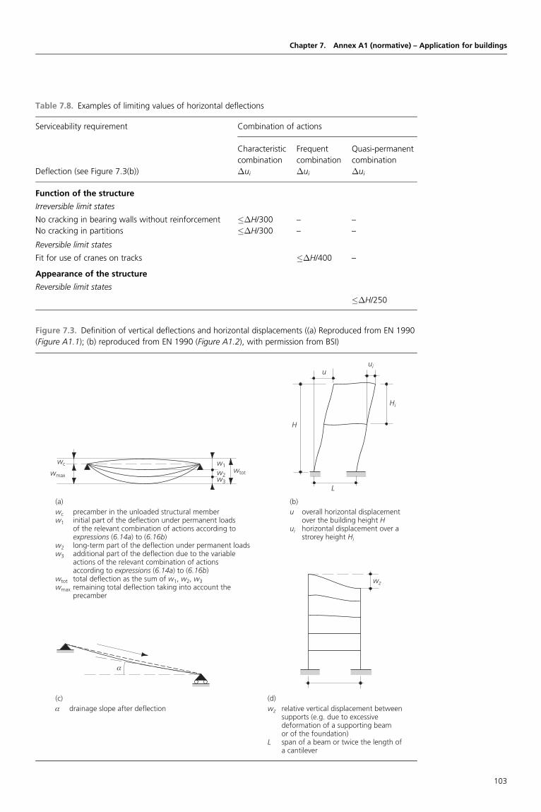
Chapter 7. Annex A1 (normative) – Application for buildings
Table 7.8. Examples of limiting values of horizontal deflections
Serviceability requirement Combination of actions
Characteristic
combination
Frequent
combination
Quasi-permanent
combination
Deflection (see Figure 7.3(b)) �ui �ui �ui
Function of the structure
Irreversible limit states
No cracking in bearing walls without reinforcement ��H/300 – –
No cracking in partitions ��H/300 – –
Reversible limit states
Fit for use of cranes on tracks ��H/400 –
Appearance of the structure
Reversible limit states
��H/250
Figure 7.3. Definition of vertical deflections and horizontal displacements ((a) Reproduced from EN 1990
(Figure A1.1); (b) reproduced from EN 1990 (Figure A1.2), with permission from BSI)
wc
(c)α drainage slope after deflection
(a)wc precamber in the unloaded structural memberw1 initial part of the deflection under permanent loads of the relevant combination of actions according to
expressions (6.14a) to (6.16b)w2 long-term part of the deflection under permanent loadsw3 additional part of the deflection due to the variable actions of the relevant combination of actions according to expressions (6.14a) to (6.16b)wtot total deflection as the sum of w1, w2, w3wmax remaining total deflection taking into account the precamber
(b)u overall horizontal displacement over the building height Hui horizontal displacement over a strorey height Hi
(d)wz relative vertical displacement between supports (e.g. due to excessive deformation of a supporting beam or of the foundation)L span of a beam or twice the length of a cantilever
α
wz
Hi
H
uiu
L
wmaxwtot
w1
w2w3
103

Clause A1.4.3(3)
Clause A1.4.3(4)
Clause A1.4.3(5)
Clause A1.4.3(6)
Clause A1.4.3(7)
Clause A1.4.4
Clause A1.4.4(2)
Clause A1.4.4(3)
Clause A1.4.4(4)
Clause 6.4.3.1(4)P
No further comments are necessary for clause A1.4.3(3).
When considering the appearance of the structure the quasi-permanent combination (expression(6.16b) of EN 1990) should be used (clause A1.4.3(4)).
No further comment is necessary for clause A1.4.3(5).
The assessment of long-term deformations due to shrinkage, relaxation or creep should beperformed using permanent actions and quasi-permanent values of the variable actions (clauseA1.4.3(6)).
No further comment is necessary for clause A1.4.3(7).
7.4.4 VibrationsWithout giving any numerical limiting value, clause A1.4.4 of EN 1990 states that the designshould take into account:
a) the comfort of the user;b) the functioning of the structure or its structural members (e.g. cracks in partitions,
damage to cladding, sensitivity of building contents to vibrations).
In general, the problem is to define more or less severe limiting values for the lowest frequenciesof vibrations of the structure or structural members which should be kept above these limitingvalues, depending upon the function of the building and the source of the vibration (clauseA1.4.4(2)).
No further comment is necessary for clause A1.4.4(3).
Possible sources of vibration that should be considered include walking (as for footbridges),synchronised movements by people (dance, etc.), machinery, ground-borne vibrations fromtraffic, and wind action. These and other sources should be specified for each project andagreed with the client (clause A1.4.4(4)).
Designers’ Guide to Eurocode: Basis of Structural Design
Example 7.1: Ultimate limit states EQU and combined limit statesEQU/STRIn accordance with EN 1990, for some structures it may be necessary to check the criteria forboth limit states EQU and STR. Examples of such structures will be examined below, toillustrate the consequences of checking two separate criteria.
Examples consideredThree well-known examples that are liable to be significantly affected are:
(a) trestle (supporting tank or conveyor)(b) T-support for viaduct(c) beam with cantilever.
Partial factors �F appliedFor ultimate limit state EQU, Table A.1.2(A) gives recommended values of �F factors fornon-geotechnical actions as follows:
g unfavourable permanent actions: 1.10g favourable permanent actions: 0.9g unfavourable variable actions: 1.5
Where the results of a verification are very sensitive to variations in the magnitude of apermanent action from place to place in the structure, the unfavourable and the favourableparts of this action shall be considered as individual actions (clause 6.4.3.1(4)P). This applies
104

Chapter 7. Annex A1 (normative) – Application for buildings
to the verification of static equilibrium and analogous limit states. In the other cases, apermanent action such as the self-weight of a structural member is considered with aunique partial factor for the whole member: it is the basis of the level II reliability method.
Concerning permanent actions, the calibration method of partial factors for EQU limitstates does not follow the calibration method of partial factors for other ultimate limitstates. It is assumed in EQU limit states that the model factor (actions and resistances) isequal to 1. Where a permanent action (e.g. self-weight) is unfavourable as regards staticequilibrium, its partial factor is equal to 1.1, and its design value may be interpreted inthe following way:
GEd¼Gm(1� ��EVG)¼Gm(1þ 0.7� 3.8� 0.03)¼ 1.08Gmffi 1.1Gm
assuming VG¼ 0.03, which is the coefficient of variation for self-weight for non-uniformdistribution.
Where the permanent action is favourable as regards static equilibrium, it is considered as aresistance:
GRd¼Gm(1� ��RVG)¼Gm(1� 3.8� 0.8� 0.03)ffi 0.9Gm
The conclusion of these basic calculations, which do not provide actual backgroundinformation on the calibration of partial factors for actions, is that the combinations ofactions for EQU ultimate limit states are not calibrated like STR/GEO combinations ofactions as regards permanent actions. Therefore, it is not appropriate to compare the twotypes of combinations of actions.
In order to produce simple illustrative examples, it is assumed here that only one character-istic value is used for each permanent action, and that the partial factors �F quoted aboveapply.
For ultimate limit states STR, two alternative sets of recommended values of �F factors aregiven for permanent actions, reflecting a choice to be made in the National Annex in relationto expressions (6.10) or (6.10a) and (6.10b).
To keep these illustrative examples simple, it is assumed that expression (6.10) will beselected. However, the conclusions may be examined as relevant to see the effect of the alter-native choice of using expressions (6.10a) and (6.10b).
The relevant values for non-geotechnical actions are thus:
g unfavourable permanent actions: 1.35g favourable permanent actions: 1.00g unfavourable variable actions: 1.50
Example (a): trestleThe model shown in Figure 7.4 can represent a trestle supporting an empty water tank, ora trestle supporting an enclosed bridge for a conveyor belt (currently unloaded), etc. Theverifications to be made are as follows:
g whether the trestle needs to be anchored down at Ag the design value of the anchorage force to be resisted by fixing at A.
Let us consider the problem of static equilibrium. Taking moments about B:
overturning moment: Md;dst ¼ hð1:5FhÞ
restoring moment: Md; stb ¼ b
20:9Gk þ bFvA
105

Designers’ Guide to Eurocode: Basis of Structural Design
Figure 7.4. Trestle with wind load
Gk
b
h
Fv,h
Fh
BA
C
For static equilibrium,
Md,stb�Md,dst
that is,
FvA � hð1:5FhÞ �b
20:9Gk
No anchorage is required if FvA is zero or negative, which occurs when
0:9Gk � 3Fh
h
bðAÞ
If this condition is not met, an anchorage is needed, and has to resist a design tension forceFd,A of
Fd;A ¼ 1:5h
bFh � 1:0
Gk
2
This force will be zero or negative when
1:0Gk � 3Fh
h
bðBÞ
The two criteria (A) and (B) can be compared as
0:9Gk � 3Fh
h
bðAÞ
1:0Gk � 3Fh
h
bðBÞ
It can be seen in this case that expression (A) always governs. Thus, when the value of3Fh(h/b) lies between 0.9Gk and 1.0Gk, the anchorage is required, but there is no designforce for it to resist. A method to treat this anomaly is explained in example (c), below.
106

Chapter 7. Annex A1 (normative) – Application for buildings
Example (b): T support for viaductThe model shown in Figure 7.5 represents a T-shaped support column assembly for aviaduct (e.g. a bridge or overhead road). For simplicity in illustrating the problem, theweight of the T support is assumed to be negligible compared with the gravity loads fromthe viaduct.
Figure 7.5 T-support for a viaduct
Gk,1 Gk,2 + Qk
a
b
Fv,A
BA
Bridges are covered in Annex A2 of EN 1990, and hence the numerical values are slightlydifferent than those for buildings, as illustrated below. However, the principle to beillustrated is the same.
The verifications to be made are, as before:
g whether the base of the support needs to be anchored down at Ag the design value of the anchorage force that the fixing at A needs to resist.
For the EQU limit state, taking moments about B:
overturning moment: Md;dst ¼a� b
2ð1:05Gk;2 þ 1:35QkÞ
restoring moment: Md;stb ¼ aþ b
20:95Gk;1 þ bFvA
For static equilibrium,
Md,stb�Md,dst
Assuming that b is small compared with a, the condition for static equilibrium can beapproximated to
FvA � a
2bð1:05Gh;2 þ 1:35Qk � 0:95Gk;1Þ ðAÞ
which would occur if
0.95Gk,1� 1.05Gk,2þ 1.35Qk
but by inspection this will never be satisfied for a symmetrical structure.
107

Designers’ Guide to Eurocode: Basis of Structural Design
An anchorage is needed: the STR limit state. This has to resist a design force Fd,vA of
Fd;vA ¼ a
2bð1:35Gk;2 þ 1:35Qk � 1:0Gk;1Þ ðBÞ
In a symmetrical structure, this force will never be zero or negative.
The two expressions (A) and (B) for FvA can be compared as
2b
aFvA � 1:05Gk;2 þ 1:35Qk � 0:95Gk;1 ðAÞ
2b
aFvA � 1:35Gk;2 þ 1:35Qk � 1:0Gk;1 ðBÞ
For the usual symmetrical case Gk,1¼Gk,2¼Gk, so the expressions reduce to
2b
aFvA � 1:35Qk þ 0:10Gk ðAÞ
2b
aFvA � 1:35Qk þ 0:35Gk ðBÞ
No anomaly arises in this case, because, as noted above, anchorage is always required, andexpression (B) always gives a value of the force to be resisted. Furthermore, the value from(B) is more than that from (A).
However, the fact that in this example there is no anomaly should not be allowed to obscurethe fact that anomalies occur in examples (a) and (c).
Example (c): beam with cantileverWe consider, in this example, a simply supported beam with a cantilever part (Figure 7.6).Only two actions are considered, represented by uniformly distributed loads: the self-weightof the beam qg and a free variable action qq. When studying a possible loss of equilibrium, thevariable action is applied only to the cantilever part.
Figure 7.6. Simply supported beam with a cantilever part
A B
a b
qg
RA
In a general manner, the expression for the vertical reaction at support A is
RA ¼ 12 aqgð�G1 � �2�G2 � �2x�QÞ
with
� ¼ b
a
and
x ¼ qq
qg
and the static equilibrium is considered as verified if RA� 0. In the following, we assume�2¼ 0.5 for the development of the numerical example. Where the static equilibrium is not
108

Chapter 7. Annex A1 (normative) – Application for buildings
ensured, we assume that an anchor is placed in A: this anchor should be designed for anappropriate resistance (STR limit state) and an appropriate stability in the ground (GEOlimit state). In the following, only the STR limit state is considered. The various partialfactors are applied as shown in Table 7.9.
Table 7.9. Example of static equilibrium
Limit state Application of actions and partial factors Reaction at support A and verification
of the limit state
EQU
A B
a b
0.90qg
1.10qg
1.50qq Values recommended in Table
7.3(A), note 1
RA1 ¼ 12aqgð0:35� 0:75xÞ
EQU verified if x� 0.47
EQU
A B
a b
1.15qg
1.35qg
1.50qq Values recommended in Table
7.3(A), note 2
RA2 ¼ 12aqgð0:475� 0:75xÞ
EQU verified if x� 0.63
Anchor placed at A to ensure stability
STR
(for anchor)
A B
a b
1.35qg
1.50qqValues recommended in Table 7.2(B)
for expression (6.10) (the factor 1.35
for permanent actions is the most
unfavourable)
RA3 ¼ 12aqgð0:675� 0:75xÞ
The reaction is negative if x> 0.90
STR
(for anchor)
A B
a b
1.15qg
1.5qqValues recommended in Table 7.2(B)
for expression (6.10a) (the most
unfavourable)
RA4 ¼ 12aqgð0:575� 0:75xÞ
The reaction is negative if x> 0.77
The functions representing the magnitude of RA are represented in Figure 7.7.
Figure 7.7. Variation of RA as a function of x
0.6750.575
0.475
0.35
Static equilibrium verifiedwith Table 7.2(A), note 1
Static equilibrium verifiedwith Table 7.2(A), note 2
Table 7.2(B)Expression (6.10a)
Table 7.2(B)Expression (6.10)
Design ofanchors
0.90 1
0.770.630.47
RA
RA4RA3
RA2
RA1
x
109

Designers’ Guide to Eurocode: Basis of Structural Design
The conclusions from this example are:
g The two sets of partial factors given in notes 1 and 2 in Table 7.2(A) are not, ofcourse, equivalent. The second set is less pessimistic than the first one for theverification of static equilibrium, but the difference appears acceptable.
g If static equilibrium is ensured by an anchor in A, this anchor should normally bedesigned considering an STR limit state for the anchor itself and probably a GEOlimit state for the anchor–ground interaction. For the STR limit state, thecombinations of actions (6.10) or (6.10a/b) given in Table 7.2(B) should normally beused, but Figure 7.7 shows that there is a range of values of x for which the anchorcannot be designed.
g In conclusion, the design rules have to be adjusted in the particular projects, but, if theverification of static equilibrium involves the resistance of stability devices, it isrecommended to use the alternative set of partial factors given in note 2 of Table 7.2(A).
Example 7.2: Example of a spread foundationLet us now consider the simple spread foundation represented in Figure 7.8. The concretefooting is assumed rigid, so that the ground response can be considered as linear.
Figure 7.8. Example of a spread foundation
B
MFh
Fv
qsup
qinf
The forces and moments caused by permanent and variable actions at the centre O are Fv (thevertical force), Fh (the horizontal force) and M (the moment).
The assessment of the width B of the footing results from the consideration of two possibleGEO limit states corresponding respectively to the capacity of the ground vertical bearingresistance and to a failure by sliding. For the sake of simplicity, only the limit state ofvertical bearing capacity will be considered.
Assuming that M� BFv the calculation of pressure under the footing gives
qsup ¼ Fv
Bþ 6
M
B2
qinf ¼Fv
B� 6
M
B2
In order to compare the ground pressure to the ground resistance, a ‘reference’ pressure, qref,is introduced, which will be compared with the design value qd:
qref ¼3qsup þ qinf
4¼ Fv
Bþ 3
M
B2
110

Chapter 7. Annex A1 (normative) – Application for buildings
The width of the footing can be obtained from the formula
B ¼ Fd; v
2qdþ
ffiffiffiffiffiffiffiffiffiffiffiffiffiffiffiffiffiffiffiffiffiffiffiffiffiffiffiffiffiffiffiFd; v
2qd
� �2
þ 3Md
qd
s
where Fd,v andMd are the design values of the vertical force and of the moment, respectively.The characteristic (subscript k) values of actions transmitted to the inner face of the footingare given in Table 7.10.
Table 7.10. Characteristic values of actions transmitted to the footing
Characteristic value Permanent action (kN) Variable action (kN)
Fk,v 380 125
Mk 70 20
The design values arising from the three approaches, using the set of � factors, are given inTable 7.11.
Table 7.11. Design values of actions transmitted to the footinga
Set Fd,v Md
B Equation (6.10)
1.35� 380þ 1.50� 125¼ 700.5
Equation (6.10)
1.35� 70þ 1.50� 20¼ 124.5
Equations (6.10a) and (6.10b)
1.35� 380þ 1.05� 125¼ 644.25 or
1.15� 380þ 1.50� 125¼ 624.5
Equations (6.10a) and (6.10b)
1.35� 70þ 1.05� 20¼ 115.5 or
1.15� 70þ 1.50� 20¼ 110.5
C 1.00� 380þ 1.30� 125¼ 542.5 1.00� 70þ 1.30� 20¼ 96.0
a Less favourable values are in bold.
Example 7.3: STR limit states in a continuous beamFor the continuous beam shown in Figure 7.9, some elementary load cases will beconsidered, with a permanent action (self-weight, G) and only one variable action (Q).The characteristic values are denoted Gk and Qk.
Figure 7.9. Continuous beam
0 1 2 3 4
Figure 7.10 shows the line of influence of the bending moment at support 1 (the positive partof the line of influence is above the beam axis). The minimum algebraic negative bendingmoment is obtained when the variable action is applied to spans corresponding tonegative parts of the line of influence.
The fundamental combination, based on expression (6.10), is
�G,supGkþ �QQk
or, with the recommended values for partial factors,
1.35Gkþ 1.50Qk
111

Designers’ Guide to Eurocode: Basis of Structural Design
Figure 7.10. Application of the variable action to the negative parts of the line of influence of the
bending moment at support 1
0 1 2 3 4
The maximum algebraic negative bending moment at support 1 is obtained when the variableaction is applied to span 0–2, corresponding to the positive part of the line of influence. Thefundamental combination, based on expression (6.10), is
�G,infGkþ �QQk
or, with the recommended values for partial factors,
1.00Gkþ 1.50Qk
Figure 7.11 shows the line of influence of the bending moment at mid-span of the secondspan (1–2). The maximum positive bending moment is obtained when the variable actionis applied to the parts of the beam corresponding to the positive parts of the line of influence.The fundamental combination, based on expression (6.10), is
�G,supGkþ �QQk
or, with the recommended values for partial factors,
1.35Gkþ 1.50Qk
Figure 7.11. Application of the variable action to the positive parts of the line of influence of the
bending moment at mid-span of span 1–2
0 1 2 3 4
The minimum positive bending moment at mid-span of the second span (1–2) is obtainedwhen the variable action is applied to spans 0–1 and 2–3, corresponding to the negativeparts of the line of influence. The fundamental combination, based on expression (6.10), is
�G,infGkþ �QQk
or, with the recommended values for partial factors,
1.00Gkþ 1.50Qk
Figure 7.12 shows the line of influence of the shear force in a cross-section of span 1–2. Themaximum positive shear force is obtained when the variable action is applied to the parts of
112

Clause A1.2.1(1)
Chapter 7. Annex A1 (normative) – Application for buildings
the beam corresponding to the positive parts of the line of influence. However, in this case theeffect of the permanent action depends on the location of the cross-section, the geometry andthe mechanical properties of the beam. For this reason, except for obvious cases, the funda-mental combination for the design, based on expression (6.10), is the more unfavourable ofthe following two expressions:
�G,supGkþ �QQk or �G,infGkþ �QQk
or, with the recommended values for partial factors,
1.35Gkþ 1.50Qk or 1.00Gkþ 1.50Qk
respectively.
Figure 7.12. Application of the variable action to the positive parts of the line of influence of the
shear force in span 1–2
0 1 2 3 4
Analogous considerations may be developed for the minimum algebraic shear force for thesame cross-section.
In conclusion, these examples show that, even for simple structures, the problem ofcombinations of actions cannot always be solved easily. For a typical building with a fewfloors, when considering two variable actions (e.g. imposed loads and wind forces) actingtogether with permanent actions, the number of load cases can be very large, and if simplifiedmethods are not used it is necessary to use good software.
Example 7.4: STR limit states in a framed structureFor the frame shown in Figure 7.13 some load cases will be considered to investigate theoverall stability for the structure. We will assume that the building is to be used as an office.
The examples of load cases are based on the consideration of only two variable actions, aspermitted by clause A1.2.1(1), note 1: imposed loads and wind actions.
Figure 7.13. Frame configuration
113

Clause 6.4.3.2
Designers’ Guide to Eurocode: Basis of Structural Design
NotationCharacteristic loads/m:
g Gkr, self-weight for the roofg Gkf, self-weight for floorsg Qkr, imposed load for the roofg Qkf, imposed floor loads.
Characteristic load/frame:
g Wk, wind loads – roof or floor.
Load casesThe fundamental combination of actions that should be used is, for example, expression(6.10) from clause 6.4.3.2:X
j� 1
�G; jGk; j ‘+’ �PP ‘+’ �Q;1Qk;1 ‘+’Xi> 1
�Q;i 0;iQk;i ð6:10Þ
As the stability of the structure will be sensitive to a possible variation of self-weights, it willbe necessary to allow for this in accordance with Table A1.25(B) of EN 1990. The values ofpartial factors are the values recommended in Annex A1 of EN 1990. Thus,
�G,inf¼ 1.0
�G,sup¼ 1.35
�Q¼ 1.5
0¼ 0.7 for imposed loads (offices) (from Table A1.1)
0¼ 0.6 for wind action for buildings (from Table A1.1)
Depending on the cross-section of structural elements under consideration, the effects ofself-weight are multiplied globally by 1.00 or 1.35 (see Table A1.2(B), note 3, in EN 1990).The variable action is a free action as is applied on the unfavourable parts of the line ofinfluence corresponding to the effect under consideration (see Section 6.4.3 of this guide).
Load case 1Treat the wind action as the dominant action (Figure 7.14).
Figure 7.14. Load case 1
1.5Wk
1.5Wk
1.5Wk
1.0 or 1.35Gkr ‘+’ 0.7(1.5Qkr)
1.0 or 1.35Gkr ‘+’ 0.7(1.5Qkf)
1.0 or 1.35Gkr ‘+’ 0.7(1.5Qkf)
114
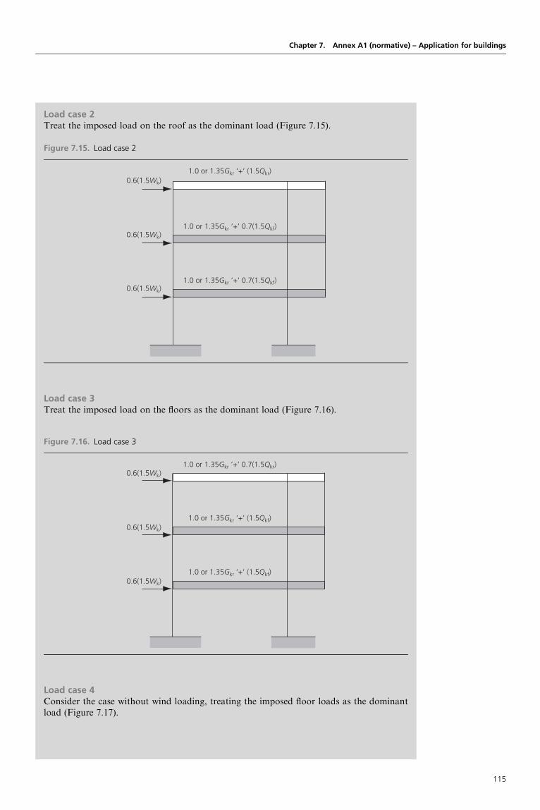
Chapter 7. Annex A1 (normative) – Application for buildings
Load case 2Treat the imposed load on the roof as the dominant load (Figure 7.15).
Figure 7.15. Load case 2
0.6(1.5Wk)
0.6(1.5Wk)
0.6(1.5Wk)
1.0 or 1.35Gkr ‘+’ (1.5Qkr)
1.0 or 1.35Gkr ‘+’ 0.7(1.5Qkf)
1.0 or 1.35Gkr ‘+’ 0.7(1.5Qkf)
Load case 3Treat the imposed load on the floors as the dominant load (Figure 7.16).
Figure 7.16. Load case 3
0.6(1.5Wk)
0.6(1.5Wk)
0.6(1.5Wk)
1.0 or 1.35Gkr ‘+’ 0.7(1.5Qkr)
1.0 or 1.35Gkr ‘+’ (1.5Qkf)
1.0 or 1.35Gkr ‘+’ (1.5Qkf)
Load case 4Consider the case without wind loading, treating the imposed floor loads as the dominantload (Figure 7.17).
115

Appendix: vibration considerations for serviceability limit statesVibration criteria can apply to three categories of ‘receiver’ (see ISO 10137) (Euro-InternationalConcrete Committee (1991):
g human occupants – including those of adjacent propertyg building contents – including those of adjacent propertyg building structure – including that of adjacent property.
Designers’ Guide to Eurocode: Basis of Structural Design
Figure 7.17. Load case 4
1.0 or 1.35Gkr ‘+’ 0.7(1.5Qkr)
1.0 or 1.35Gkr ‘+’ (1.5Qkf)
1.0 or 1.35Gkr ‘+’ (1.5Qkf)
Load case 5Consider the case without wind loading, treating the imposed roof load as the dominant load(Figure 7.18).
Figure 7.18. Load case 5
1.0 or 1.35Gkr ‘+’ (1.5Qkr)
1.0 or 1.35Gkr ‘+’ 0.7(1.5Qkf)
1.0 or 1.35Gkr ‘+’ 0.7(1.5Qkf)
Note: when the wind loading is reversed, another set of arrangements will need to beconsidered.
116

From the reaction of people to vibrations, vibration criteria can be further classified as thosepertaining to:
g sensitive occupation, such as hospital operating roomsg regular occupation, such as offices and residential areasg active occupation, such as assembly areas or places of heavy industrial work.
Vibration criteria arising from human occupation are given in terms of acceptance criteriaaccording to ISO 2631 (Euro-International Concrete Committee, 1978; ISO, 1976, 1980).These criteria include the relevant acceleration–frequency line for a selected exposure time anddirection of vibration.
The vibration criteria selected for the contents of buildings should allow the satisfactory func-tioning of sensitive instruments or manufacturing processes. Because of the great variety ofsuch equipment and processes it is not possible to present any fixed levels of vibration amplitudethat will ensure satisfactory operation. Limits for the movements of machines are usually speci-fied by considering the maximum deflection and frequency.
The vibration criteria selected for building structures should avoid the development of minordamage to structural and non-structural elements. The permissible levels of vibration effectsdepend on the type of structure, and its age, importance and other aspects. The correspondinglimits not covered by acceleration–frequency lines or deflection–frequency lines may be expressedin terms of maximum stress, maximum stress range or maximum deformation. These limitsshould be specified in the design specifications.
For example, when conditions for human comfort need to be specified, they should be given interms of an acceleration criteria according to ISO 2631 (Euro-International Concrete Committee,1991). The acceptance criteria should include a relevant acceleration–frequency line for theselected exposure time and direction of vibration. For continuous and shock-induced vibrationsin buildings (traffic and pile driving), see ISO 2631-2 (ISO, 1980), for the range from 1 to 80 Hz,and for vibration caused by wind see ISO 2631-3 (ISO, 1976), for the range from 0.01 to 1 Hz.
REFERENCES
Euro-International Concrete Committee (1978) International System of Unified Standard Codes of
Practice for Structures. FIB, Lausanne. CEB Bulletins 124 and 125.
Euro-International Concrete Committee (1991) Reliability of Concrete Structures – Final Report of
Permanent Commission 1. FIB, Lausanne. CEB Bulletin 202.
ISO (1976) ISO 2854. Statistical interpretation of data. Techniques of estimation and tests relating
to means and variances. ISO, Geneva.
ISO (1980) ISO 2602. Statistical interpretation of test results. Estimation of the mean. Confidence
interval. ISO, Geneva.
FURTHER READING
BSI (1985) BS 8110. Structural use of concrete. Part 1: Code of practice for design and
construction. BSI, Milton Keynes.
BSI (1990) BS 5950. Structural use of steel work in building. Part 1: Code of practice for design in
simple and continuous construction: hot rolled sections. BSI, Milton Keynes.
BSI (1996) BS 6399-1. Loading for buildings. BSI, Milton Keynes.
Building Research Establishment (1997) Response of Structures Subject to Dynamic Crowd Loads.
BRE, Watford. Digest 426.
Calgaro JA (1996) Introduction aux Eurocodes – Securite des Constructions et Bases de la Theorie de
la Fiabilite. Presses de l’Ecole Nationale des Ponts et Chaussees, Paris.
Euro-International Concrete Committee (1985) Basic Notes on Model Uncertainties – State-of-the-
art Report. FIB, Lausanne. CEB Bulletin 170.
Euro-International Concrete Committee (1991) Reliability of Concrete Structures – Final Report of
Permanent Commission I. FIB, Lausanne. CEB Bulletin 202.
European Committee for Standardization (1994) ENV 1991-1. Basis of design. CEN, Brussels.
European Committee for Standardization (2001) EN 1990. Eurocode: basis of structural design.
CEN, Brussels.
Chapter 7. Annex A1 (normative) – Application for buildings
117

Finnish Ministry of the Environment, Housing and Building Department (2000) Probabilistic
Calibration of Partial Safety Factors (Eurocode and Finnish Proposal). Helsinki.
Holicky M and Markova J (2000) Verification of load factors for concrete components by
reliability and optimization analysis: background documents for implementing Eurocodes.
Progress in Structural Engineering and Materials 2(4): 502–507.
ISO (1985) ISO 2631-1. Evaluation of Human Exposure to Whole-body Vibration. Part 1: General
Requirements. ISO, Geneva.
ISO (1985) ISO 2631-3. Evaluation of human exposure to whole-body vibration. Part 3: Evaluation
of exposure to whole-body z-axis vertical vibration in the frequency range 0.1 to 0.63 Hz. ISO,
Geneva.
ISO (1989) ISO 2631-2. Evaluation of human exposure to whole-body vibration. Part 2:
Continuous and shock-induced vibrations in buildings (1–80 Hz). ISO, Geneva.
ISO (1992) ISO 10137. Bases for Design of structures – serviceability of structures against
vibration. ISO, Geneva.
ISO (1997) ISO 2394. General principles on reliability for structures. ISO, Geneva.
Joint Committee on Structural Safety (2001) Probabilistic Model Codes [working document]. JCSS,
Zurich.
Mathieu H (1979) Manuel Securite des Structures. FIB, Lausanne. CEB Bulletins 127 and 128.
SAKO and Joint Committee of NKB and INSTA-B (1999) Basis of Design of Structures. Proposal
for Modification of Partial Safety Factors in Eurocodes. SAKO, Helsinki.
Sorensen JD, Hansen SO and Nielsen TA (2001) Partial safety factors and target reliability level in
Danish codes. Proceedings of Safety, Risk, and Reliability. IABSE, Malta, pp. 179–184.
Tursktra CJ (1970) Application of Bayesian Decision Theory. Study No. 3: Structural Reliability and
Codified Design. Solid Mechanics Division, University of Waterloo, Ontario.
Vrouwenfelder T (2001) JCSS Probabilistic model code. Proceedings of Safety, Risk, and Reliability.
IABSE, Malta, pp. 65–70.
Designers’ Guide to Eurocode: Basis of Structural Design
118

Designers’ Guide to Eurocode: Basis of Structural DesignISBN 978-0-7277-4171-4
ICE Publishing: All rights reserved
http://dx.doi.org/10.1680/bsd.41714.119
Chapter 8
Management of structural reliabilityfor construction works
This chapter is concerned with the reliability management aspects of EN 1990. The materialdescribed in this chapter is covered by Annex B, in the following clauses:
g Scope and field of application Clause B1g Symbols Clause B2g Reliability differentiation Clause B3g Design supervision differentiation Clause B4g Inspection during execution Clause B5g Partial factors for resistance properties Clause B6
8.1. Scope and field of applicationAnnex B provides additional guidance to clause 2.2 (reliability management), which is one of theprincipal requirements in EN 1990. This chapter also applies to appropriate clauses in EN 1991to EN 1999 (clause B1(1)), where reliability differentiation rules are specified for a few particularaspects.
Clause B1(2) explains the layout and style of Annex B and its links to clause 2.2 of EN 1990 andrequires no comment in this guide.
Annex B is an informative annex and is formulated in a such a way so as to provide a frameworkto allow different reliability levels, to be used if desired; it provides guidance on the methodswhich can be adopted at the national level to use these concepts (clause B1(3)).
With reference to clauses B1(2) and B1(3) the main tools selected in Annex B of EN 1990 for themanagement of structural reliability of construction works are:
g differentiation by values of � factorsg alteration of partial factorsg design supervision differentiationg measures aimed to reduce errors in design and execution of the structure, and gross human
errorsg adequate inspection and maintenance according to procedures specified in the project
documentation.
BackgroundThe purpose of reliability differentiation is the socio-economic optimisation of the resourcesto be used to build construction works, taking into account all the expected consequences offailure and the cost of construction.
8.2. SymbolsThe subscript ‘FI’ is used to indicate a factor applicable for reliability differentiation; ‘F’ indi-cates a partial factor for an action, and ‘I’ an importance factor, similar to the factor introducedin EN 1998. A detailed explanation of the reliability index � is given in Annex C of EN 1990 andin Chapter 9 of this guide (clause B2).
Clause 2.2
Clause B1(1)
Clause B1(2)
Clause 2.2
Clause B1(3)
Clause B1(2)
Clause B1(3)
Clause B2
119

Clause B2(1)
8.3. Reliability differentiation8.3.1 Consequence clausesFor the purpose of reliability differentiation, Annex B of EN 1990 establishes consequencesclasses (CC) (clause B2(1)). Annex B defines quantitatively three consequences of failure ormalfunction of a structure, which are defined as follows:
g consequences class CC3 – high consequence for loss of human life, or economic, social orenvironmental consequences very great
g consequences class CC2 – medium consequence for loss of human life, economic, social orenvironmental consequences considerable
g consequences class CC1 – low consequence for loss of human life, and economic, social orenvironmental consequences small or negligible.
Examples for CC3, CC2 and CC1 are given in Table 8.1.
Designers’ Guide to Eurocode: Basis of Structural Design
Table 8.1. Consequence class matrix
Frequency of use Consequences of failurea
Lowb Mediumc Highd
Low CC1 CC2 CC3
Medium CC2 CC2 CC3
High Not applicable CC3 CC3
a Consequences of failure include the consideration of:
g loss of human life (sometimes called the safety of people)g environment and social consequences (e.g. when a failure causes an environmental catastrophe)g economic consequences (e.g. the cost of replacement of a building and its contents and the cost of the loss of its
use)g the value of the loss of human life.
b Includes agricultural buildings where people do not normally enter, sheds and greenhouses.c Includes hotels, schools, residential buildings and access bridges (e.g. to farms).d Includes grandstands, theatres, significant high-rise buildings and bridges.
BackgroundThe International Council for Research and Innovation in Building and Construction(CIB, 2001) defined ‘risk’ and ‘acceptable risk’ as follows.
RiskRisk is a measure of the danger that undesired events represent for humans, the environmentor economic values. Risk is expressed in the probability and consequences of the undesiredevents. Risk is often estimated by the mathematical expectation of the consequences of anundesired event: it is then the product ‘probability� consequences’.
Acceptable riskAcceptable risk is a level of risk which is generally not seriously perceived by an individual orsociety, and which may be considered as a reference point in criteria of risk. Cultural, social,psychological, economic and other aspects will influence societal risk perception.
The concept of ‘acceptable’ risk of human death resulting from structural failure raises verysensitive questions, concerning public perception (CIB, 2001). Fatalities due to accidents,taken from recent figures (Euro-International Concrete Committee (1978) (Table 8.2) areconsidered to reflect the public perception of acceptability of fatalities for different typesof accident and exposure to serious hazards.
As can be seen from Table 8.2, the public demands a very high level of reliability in buildings.Partial factor design is based on the consideration of limit states which are, in mostcommon cases, classified into ultimate and serviceability limit states, idealising undesirable
120

EN 1990, as do all the other Eurocodes, uses the concept of partial factor design and, embodiedin the values of the partial factors, there are implicit ‘acceptable’ or ‘accepted’ risk levels.However, ‘risk’ and ‘risk analysis’ are not defined in EN 1990. This is because the word ‘risk’has a different meaning to an engineer, an insurance specialist, an economist, etc. In the
Chapter 8. Management of structural reliability for construction works
phenomena. The design is such that their probability of occurrence in 50 years is less thanan ‘acceptable’ value. Figure 8.1 shows the usual ranges of values for the ultimate andserviceability limit states associated with a probability of failure over a 50 year period.
Table 8.2. ‘Accepted’ risks of death due to exposure to various hazardsa
Hazard Risk:
�10�6 p.a.
Hazard Risk:
�10�6 p.a.
Building hazards
Structural failure (UK)
Building fires (Australia)
0.14
4
Occupations (UK)
Chemical and allied industries
Ship building and marine engineering
Agriculture
Construction industries
Railways
Coal mining
Quarrying
Mining (non-coal)
Offshore oil and gas (1967–76)
Deep sea fishing (1959–78)
85
105
110
150
180
210
295
750
1 650
2 800
Natural hazards (USA)
Hurricanes (1901–72)
Tornadoes (1953–71)
Lightning (1969)
Earthquakes (California)
0.4
0.4
0.5
2
Sports (USA)
Cave exploration (1970–78)
Glider flying (1970–78)
Scuba diving (1970–78)
Hang gliding (1977–79)
Parachuting (1978)
45
400
420
1 500
1 900
General accidents (USA, 1969)
Poisoning
Drowning
Fires and burns
Falls
Road accidents
20
30
40
90
300
All causes (UK, 1977)
Whole population
Woman aged 30 years
Man aged 30 years
Woman aged 60 years
Man aged 60 years
12 000
600
1 000
10 000
20 000
a Risk expressed as the probability of death for typical exposed person per calendar year.
Figure 8.1. Probabilities associated with limit states
Value associated with β = 3.8(ULS, 50 year reference period)
Value associated with β = 1.5(SLS, 50 year reference period)7.2 × 10⁻⁵ Serviceability limit
states (SLS)
Ultimate limit states (ULS)
10–6 10–5 10–4 10–3 10–2 10–1 1
121

Clause B3.1(2)
Clause B3.1(3)
Clause B3.2(1)
Clause B3.2(2)
Clause C5(1)
Clause B3.2(3)
same way, the term ‘risk analysis’ has no meaning if the procedure to carry out an analysis isnot accurately defined. For example, there is no universal methodology for performing a riskanalysis for a heavy vehicle or ship impacting a bridge pier.
Thus, the criterion for classification in EN 1990 is the importance in terms of consequences offailure of the structure or structural members (clause B3.1(2)). It is widely accepted that thereliability level of a structure should be higher the greater the consequences of failure. Theselection of the consequence class and different levels of reliability requires consideration of anumber of appropriate aspects, including:
g the frequency of useg the cause and/or mode of attaining a limit stateg the possible consequences of failure in terms of risk to life, injury and potential economic
lossesg political requirements and public aversion to failureg the expense and procedures necessary to reduce the risk of failure.
Table 8.1, a matrix indicating appropriate consequence classes, complements Table B1 ofEN 1990, and will aid the selection of a consequence class for a construction works, structuralmember or component.
Within a particular construction works, different structural members or components may have tobe designated with the same, higher or lower consequences of failure (clause B3.1(3)). As anexample, consider a medium-sized hotel building, whose public rooms are used for conferences,meetings and social events (e.g. weddings). It could be that the public rooms have large spans,where the implications of their collapse (i.e. consequences of failure) would be high. In thiscase, the client’s representative (i.e. the designer) or checking authority may designate theelements supporting the public rooms CC3, and the structural elements supporting hotelbedrooms as CC2. The hotel building as a whole would usually be classed CC2 or CC3,depending on its consequences of failure.
8.3.2 Differentiation by � valuesIn Annex B of EN 1990, three reliability classes, which are defined by the � reliability indexconcept (clause B3.2(1)), are associated with the three consequences classes (clause B3.2(2)).Consequences classes CC1, CC2 and CC3 are associated with reliability classes RC1, RC2 andRC3, respectively.
The reliability index � is a function of the probability of failure, and is explained in Chapter 9 ofthis guide. The relationship between the probability of failure Pf and � is given in Table 8.3 (seeclause C5(1) and Figure 8.1).
Table 8.4 establishes a link between consequences classes, reliability classes and values for thereliability index �. It includes information from Table B2 of EN 1990, which is concerned withultimate limit states only. Table 8.4 is extended to include fatigue and serviceability limit states.
According to the note to Table B2 of EN 1990 (clause B3.2(3)), a design using EN 1990 with therecommended values of partial factors given in Annex A1 (application for buildings) and the
Designers’ Guide to Eurocode: Basis of Structural Design
Table 8.3. Relationship between Pf and �
Pf �
10�1 1.28
10�2 2.32
10�3 3.09
10�4 3.72
10�5 4.27
10�6 4.75
10�7 5.20
122

other design Eurocodes with the recommended material resistance factors is generally consideredto lead to a structure with a � value greater than 3.8 for a 50 year reference period andcorresponding to RC2 and CC2.
EN 1990 recognises that risks associated with structural failure, related to the present time,are reasonable, and its recommendations are based on this recognition, thus associating themedium-class consequences (i.e. CC2) with a minimum probability of failure of 7.2� 10�5 in50 years, corresponding to �¼ 3.8 (see Figure 8.1).
The probability of failure and its corresponding � index are only notional values that do notnecessarily represent actual failure rates (which depend mainly on human errors). They areused as operational values for code calibration purposes and comparison of reliability levels ofstructures.
Many investigations have been performed (e.g. see Euro-International Concrete Committee,1991) to determine � factors, corresponding to ultimate limit states for structures or structuralelements designed using various codes and realistic data concerning actions and resistances.These investigations consistently show a significant scatter of � values. A comparable scatterwould probably be found when using the Eurocode suite. This is due to the fact that allcodified models (e.g. models for actions, resistances and structural analysis), including numericalvalues, are unavoidably approximate in order to simplify the design in the most common casesand be more or less appropriate for each particular case. Figure 8.2 is a histogram of therelative frequency of � values for an assumed large number of calculations.
The difference between bridges and buildings is due to the higher levels of design supervision, thecontrol of material quality and inspection during execution that is generally given to the designand execution of bridges. This is an example of reliability differentiation by the requirements forquality levels.
A certain proportion of construction works may have a � value less than 3.8 in 50 years. Manyengineers consider that this value should be a target value for the calibration of the whole systemof actions–resistances–partial factors. Considering the case of buildings, the average value of the� factor (see Figure 8.2) could be lowered but with a corresponding reduction in the scatter, sothat the proportion of construction works below �¼ 3.8 would remain approximately the same.Such a lowering of the average � index value can be obtained by using expressions (6.10a) and(6.10b) of EN 1990 for combinations of actions applicable to ultimate limit states of resistanceinstead of the classical expression (expression (6.10)) of EN 1990. See also Chapters 6 and 7 ofthis guide.
The number of verification rules for serviceability limit states in the Eurocodes is limited, andit has been assumed that the reliability levels for the ultimate limit states will not be reduced,
Chapter 8. Management of structural reliability for construction works
Table 8.4. Consequences and reliability classes, and values for the reliability index �
Consequences Reliability Values for �
class class
Ultimate limit states Fatigue Serviceability
1 year
reference
perioda
50 year
reference
perioda
1 year
reference
period
50 year
reference
period
1 year
reference
period
50 year
reference
period
CC3 RC3 5.2 4.3
CC2 RC2 4.7 3.8 1.5–3.8 2.9 1.5
CC1 RC1 4.2 3.3
(1) (2) (3) (4) (5) (6) (7) (8)
a The values for � are recommended minimum values in columns 3 and 4.
123

Clause B3.3(1)
Clause B3.3
Clause B3.3(2)
Clause B3.3(3)
thus indirectly covering some of the serviceability limit state verifications. Use of expressions(6.10a) and (6.10b), however, will reduce reliability levels and therefore make it necessary toconsider the verification for the serviceability limit states more thoroughly than when expres-sion (6.10) is used.
The normal reliability level can be maintained by the adoption of higher quality levels in designand execution. Other means have been used in the Eurocodes. For example, the adjusting factors� and � of traffic loads given in EN 1991-2 are normally intended to keep reliability levelsconstant under different traffic conditions, but they might also be used to define reliabilityclasses (to be applied, for example, to existing bridges).
8.3.3 Differentiation by measures relating to partial factorsA reliability differentiation can be envisaged by distinguishing classes of �F factors to be usedin the fundamental combinations of actions for persistent design situations. Clause B3.3(1)suggests the use of a multiplication factor KFI applicable to � factors of unfavourable actions:equal to 1.0 for the medium reliability class (RC2), it can be taken equal to 0.9 for reliabilityclass RC1 and 1.1 for reliability class RC3. Attention is drawn to the fact that a simultaneoususe of expression (6.10b) with ¼ 0.85 and KFI¼ 0.9 would lead to a global �¼ 1 applicablefor unfavourable permanent actions; an application of Annex B to EN 1990 should not use all‘favourable’ possibilities in reducing reliability levels, but if this is done it should be withextreme caution.
On the other hand, instead of applying the KFI factor of 1.1 to �F for actions which are unfavour-able for CC3 structures, it is normally preferable to apply other measures, for example, higherlevels of quality control (note to Table B3, clause B3.3).
Reliability differentiation may also be applied through the partial factors of resistance �M(see Section 8.6 and also ‘Eurocode 3: Design of steel structures’, which describes a reliabilitydifferentiation in relation to a fatigue verification (clause B3.3(2)).
Experience suggests that a differentiation of partial factors with the limits given in Table B3 ofAnnex B of EN 1990 has no significant influence on the reliability level of the structure;however, any lowering of factors for economic reasons must be compensated for by a higherlevel of quality control.
Clause B3.3(3) recognises that the reliability classes of construction works may be linked to therequirements for quality levels of the design (DSL; see Section 8.4) and execution process (IL; seeSection 8.5).
Designers’ Guide to Eurocode: Basis of Structural Design
Figure 8.2. Frequency of � values for construction works
Rela
tive
freq
uenc
y
1 2 3 4 5 6 7β
Average β value
Buildings
Bridges
124

BackgroundDue, largely, to increased competition among material producers, there has been a tendencywithin the construction industry to reduce safety margins (in particular partial factors) forboth actions and material resistance. This together with other rules that can lower reliabilitylevels and the increased use of IT packages for analysis will result in buildings which willbecome more slender, with reduced robustness; and hence a much reduced reservestrength in comparison to buildings designed about 15 years ago. This trend is becomingvery apparent among, for example, product manufacturers.
The Eurocodes permit the choice of various factors, for example:
g reliability differentiationg different load combination expressions through a National Annexg partial factors through a National Annexg imposed load valuesg �cc factors for the value of the design compressive strength of concrete resistance at
the ultimate limit stateg �M factors for materials, etc.
If all these factors are chosen with the primary objective of economy, this would lead tostructures or structural elements with a lowered level of reliability and structures withreduced reserve strengths, and thus the risk of failure and collapse is increased.
Clause 2.2(6) (see Chapter 2) states that the different measures to reduce the risk of failure maybe interchanged to a limited extent provided that the required reliability level is maintained.Chapter 2 of this guide cites an example where during a refurbishment it may be necessary tocompensate for a slightly lower partial factor by a high level of quality management. Othersituations include where, for reasons of economy, a lower KFI may be chosen but compensatedfor by a higher level of design supervision and quality control, in particular for high-volumefactory-produced standard units (e.g. lighting columns or standard beams) (clause B3.3(4)).
8.4. Design supervision differentiationFor measures relating to quality management and measures aimed at reducing errors in designand execution of the structure and gross human errors, Annex B of EN 1990 introduces theconcept of design supervision levels.
Experience shows that:
g gross errors are caused by human factors (e.g. violation of accepted rules for design andexecution)
g almost every serious failure is caused by errors in design and executiong gross errors can only be avoided by quality control levels for design and supervision.
The design supervision levels DSL3, DSL2 and DSL1 (corresponding respectively to CC3, CC2and CC1) represent the various organisational quality control steps taken to ensure the reliabilityof a structure, which may be used together with other measures, such as the classification ofdesigners and checking authorities (clause B4(1)).
Clause 2.2(5) allows these design supervision levels to be related to the reliability classes or to bechosen on the basis of the importance of the structure (i.e. consequence classes) and inaccordance with the national requirements or design brief. The three design supervision levelsare shown in Table 8.5 (based on Table B4 of EN 1990), and should be implemented throughappropriate quality management measures (clause B4(2)).
Differentiation is made on the basis of supervision of the design at the design stage of thestructure, thus if the quality control measures are more stringent such as third-party checking,then a higher reliability class can be expected than for normal supervision (i.e. self-checking).
Clause 2.2(6)
Clause B3.3(4)
Clause B4(1)
Clause 2.2(5)
Clause B4(2)
Chapter 8. Management of structural reliability for construction works
125

Clause B4(3)
Clause B4(4)
Clause B5(1)
Clause B4(3) goes further, to say that design supervision differentiation may also include aclassification of designers and/or design inspectors (checkers, controlling authorities, etc.)depending on their competence and experience, and their internal organisation, for therelevant type of construction works being designed because the type of construction works,the materials used and the structural forms adopted can affect the classification. For example,EU member states or clients could specify that certain design consultants with expertise incertain fields and a proven track record should provide the extended supervision (i.e. third-party supervision).
Clause B4(4) points out that design supervision differentiation can consist of:
g a more refined detailed assessment of the nature and magnitude of actions to be restrictedby the structure or
g a system of design load management actively or passively to restrict these actions.
A more detailed understanding of the action creating a hazard in a structure and then activelyor passively controlling it (e.g. warning systems for load exceedance on floors in intelligentbuildings) is a part of design supervision differentiation.
8.5. Inspection during executionClause B5(1) introduces inspection classes IL1 to IL3, which are differentiated on the basis of thelevel of inspection during execution (Table 8.6).
Annex B of EN 1990 recommends inspection levels to be linked to the reliability classespreviously defined. It also states that the inspection levels should define the subjects to becovered by the inspection of products and execution of works including stating the scope ofthe inspection, thus the inspection rules will vary from one structural material to another,and reference should be made to the relevant CEN execution standards. Tables 8.7 and 8.8
Designers’ Guide to Eurocode: Basis of Structural Design
Table 8.5. Design supervision levels
Design supervision level Characteristics Minimum recommended requirements for checking of
calculations, drawings and specification
DSL3 (relating to RC3/CC3) Extended
supervision
Third-party checking: checking performed by an
organisation different from that which prepared the
design
DSL2 (relating to RC2/CC2) Normal
supervision
Checking by personnel different from those originally
responsible and in accordance with procedure of the
organisation
DSL1 (relating to RC1/CC1) Normal (basic)
supervision
Self-checking: checking performed by the person who
prepared the design
For examples see Table 8.1, footnotes b, c and d
Table 8.6. Inspection levels (IL)
Inspection level Characteristics Requirements
IL3 (relating to RC3/CC3) Extended inspection Third-party inspection
IL2 (relating to RC2/CC2) Normal inspection Inspection in accordance with the
procedures of the organisation
IL1 (relating to RC1/CC1) Normal (basic) inspection Self-inspection
For examples see Table 8.1, footnotes b, c and d
126

Chapter 8. Management of structural reliability for construction works
Table 8.7. Examples of design supervision levels for activities (to be regarded as a guide only)
Activity Normal (basic)
supervision
Normal
supervision
Extended
supervision
Basis for design as related to the intended function and use
of the structure
X X X
Basis for evaluation of soil conditions X
Assumptions for actions, and calculation models for actions X X X
Calculation model(s) for structural design (calculation of
action effects)
X X
Relevance of assumed material properties X X
Assessment of design values of soil parameters X X X
Identification of critical components, areas and
cross-sections
X X
Checks of global equilibrium X X X
Checks of structural calculations by independent
calculations
X X
Compliance of calculations with drawings X X X
Specification of relevant requirements for inspection of
execution
X X
Table 8.8. Execution activities: examples of inspection classes with regard to concrete construction (to be
regarded as a guide only)
Activity Normal (basic)
inspection 1
Normal
inspection 2
Extended
inspection 3
Scaffolding,
formwork
Random sampling Major scaffolding and
formwork to be inspected
before concreting
All scaffolding and
formwork to be inspected
Ordinary
reinforcement
Random checking Major reinforcement to be
inspected before concreting
All reinforcement to be
inspected before concreting
Prestressing steel Not applicable All prestressing steel to be
inspected before concreting
Embedded items According to project
specification
Erection of precast
elements
According to project
specification
Delivery and casting
of concrete
Occasional checks Occasional checks Check of entire process
Curing and finishing
of concrete
None Occasional checks Check of entire process
Stressing of
prestressing steel
Not applicable According to project
specification
Documentation of
inspection
Not required Required
The inspection of execution also consists of documentation of product properties using EN 206, etc.
127

Clause B2.6(1)
give examples of activities to be checked for the three inspection levels for both the design andexecution stages.
8.6. Partial factors for material propertiesClause B2.6(1) also recommends that a partial factor product property, or a member resistance,can be reduced if an inspection class higher than that required according to Table 8.6 and/ormore severe requirements are used during the manufacture of a product or supervision duringexecution.
As stated in Section 8.4, a differentiation in partial factors has a significant impact on the cost of aproduct and the cost of the construction works, and as such is desired by many parts of theconstruction industry including product manufacturers, clients and organisations involved inPFI (private finance initiatives). Such a differentiation must be justified by increased inspection,thus increasing the probability of reaching the target properties.
Resistance product properties which are of particular importance for structural reliability aregeometry and strength of materials.
REFERENCES
CIB (2001) Risk Assessment and Risk Communication in Civil Engineering. CIB, Rotterdam. CIB
Report 259.
Euro-International Concrete Committee (1978) International System of Unified Standard Codes of
Practice for Structures. FIB, Lausanne. CEB Bulletins 124 and 125.
Euro-International Concrete Committee (1991) Reliability of Concrete Structures – Final Report of
Permanent Commission 1. FIB, Lausanne. CEB Bulletin 202.
FURTHER READING
Euro-International Concrete Committee (1991) CEB–FIP Model Code 90. FIB, Lausanne. CEB
Bulletins 203–205.
Menzies JB (1995) Hazards, risks and structural safety. Structural Engineer 73: No. 21.
Reid SG (1999) Perception and communication of risk, and the importance of dependability.
Structural Safety 21: 373–384.
SAKO (1995) NKB Committee and Work Reports 1995:03 E: Basis of Design of Structures –
Classification and Reliability Differentiation of Structures. SAKO, Helsinki.
Tietz SB (1998) Risk analysis – uses and abuses. Structural Engineer 76: No. 20.
Designers’ Guide to Eurocode: Basis of Structural Design
128

Designers’ Guide to Eurocode: Basis of Structural DesignISBN 978-0-7277-4171-4
ICE Publishing: All rights reserved
http://dx.doi.org/10.1680/bsd.41714.129
Chapter 9
Basis for partial factor design andreliability analysis
This chapter is concerned with the basis for partial factor design and with the general concept ofstructural reliability. The material described in this chapter is covered in the informative Annex Cof EN 1990, in ten clauses:
g Scope and field of application Clause C1g Symbols Clause C2g Introduction Clause C3g Overview of reliability methods Clause C4g Reliability index � Clause C5g Target values of reliability index � Clause C6g Approach for calibration of design values Clause C7g Reliability verification formats in Eurocodes Clause C8g Partial factors in EN 1990 Clause C9g 0 factors Clause C10
This chapter includes seven numerical examples illustrating general calculation proceduresdescribed in Annex C of EN 1990. The appendix to this chapter includes five Mathcad sheetsthat can be used to apply general procedures in practical examples calculations. (Mathcad is asoftware package that performs calculations and produces documents containing text, equationsand graphs.)
9.1. Scope and field of applicationThe Eurocodes are based on the partial factor method (as described in Section 6 and Annex A ofEN 1990). Detailed information and theoretical backgrounds for the partial factor method areprovided in Annex C (clause C1(1)) of EN 1990. Clause C1(2) states that Annex C provides infor-mation on structural reliability methods, on the application of these methods for determinationof design values and partial factors by calibration, and on the design verification formats used inthe Eurocodes.
9.2. SymbolsThe symbols and terms (clause C2) used in Annex C of EN 1990 mostly coincide with the tradi-tional notation used in structural reliability. It should, however, be noted that alternative termscan be found in ISO 2394 and other literature on structural reliability. For example, the symbol gused in Annex C for the ‘performance function’ is often called the ‘limit state function’ or the‘state function’, or, in some simple cases, the ‘reliability (safety) margin’. Another importantterm, ‘survival probability’ Ps, is often called ‘reliability’ (see also ISO 2394 (ISO, 1998)).Some terms used in Annex C, for example, ‘probabilistic, semi-probabilistic, deterministicmethods’ and classification of ‘level I, II and III reliability methods’, may be used in the literaturein slightly different ways. Additional terms (such as ‘design value method’, used previously inENV 1991-1 but not in EN 1990) may be found in ISO 2394 and other literature.
Supplementary symbols and terms to those given in clause C2will be introduced in this chapter inorder to provide more comprehensive background information. For example, ’(X) will be usedfor the probability density function of a variable X, and X for a vector of all basic variables (thissymbol is also used in Chapter 10 of this guide and in Annex D of EN 1990).
Clause C1(1)
Clause C1(2)
Clause C2
Clause C2
129

Clause C3(1)
Clause 3.4(1)P
Clause C3(1)
Clause C3(2)
Clause C3(3)
Clause C6
Clause C4(1)
Clause C2
Clause C4(1)
Clause C4(2)
Clause C4(3)
Clause C4(4)
Clause 3.5(5)
Clause C5(1)
9.3. IntroductionBasic variables, denoted in general by a vector X, include three fundamental categories ofvariables entering load and resistance models in any design verification (Section 4 and AnnexC (clause C3(1)) of EN 1990):
g action variables Fg resistance variables Rg geometric properties a.
As a rule, each category consists of a number of variables, for example, actions F may consist ofseveral permanent actions G and variable actions Q. In verification of a structure, all basicvariables can be substituted by their design values, which are used in structural and loadmodels to verify that no limit state is exceeded (clauses 3.4(1)P and C3(1)).
The design values of basic variables are determined from their characteristic values using partialand factors (see Section 6 of EN 1990). Numerical values of these factors can be determinedusing two basic procedures mentioned in clause C3(2):
1 calibration to past experience2 application of probabilistic reliability theory.
As a rule, both procedures for the determination of � and factors are combined in order toincrease the credibility of obtained results. When probabilistic reliability theory is applied,then the values of � and factors should be determined in such a way (clause C3(3)) thatthe reliability level is as close as possible to the target reliability given in clause C6.Thus, the reliability level of a structure should be neither lower (for safety reasons) norsignificantly greater (for economic reasons) than the target level as both cases may lead toundesirable consequences. It should be mentioned that the � and factors are mostlydetermined using procedure (1), calibration to past experience, based on statistical evaluationof experimental data and field observations. However, structural reliability methods nowprovide increasingly efficient background information on all reliability elements usedin Eurocodes.
9.4. Overview of reliability methodsThe overview of reliability methods (clause C4(1)) given in Figure C1 of EN 1990 is essentially thesame as in the previous version (ENV 1991-1), and need not be discussed in detail here. However,as already mentioned in clause C2, EN 1990 uses slightly different terminology from ISO 2394.It is a consequence of the fact that the terminology used in clauses C4(1), C4(2) and C4(3)(probabilistic, deterministic methods, levels I, II and III) and methodology (FORM, semi-probabilistic methods) are still not fully harmonised in reliability theory. In particular, theterm ‘semi-probabilistic methods (level I)’ is not generally accepted, and may even be confusing,as it is not defined in EN 1990. Most likely it refers to the ‘design values method’ as defined in theprevious document ENV 1991-1 and in ISO 2394.
As already mentioned above, the present generation of Eurocodes is still mostly calibrated toprevious experience (clause C4(4)) using procedure (1) described above. Nevertheless, thisprocedure is increasingly effective when combined with other calibration procedures indicatedin Figure C1 (e.g. using full probabilistic or semi-probabilistic (design value) methods). Asmentioned in Chapter 3, in accordance with clause 3.5(5) a design directly based on probabilisticmethods may be used as an alternative. Although specific conditions for the use of probabilisticmethods should be given by the relevant authority, Annex C of EN 1990 should provide abasis.
9.5. Reliability index �The traditionally used reliability index � is one of the most frequently used reliability measuresof structures (clause C5(1)). It should be underlined that it is a quantity fully equivalent to theprobability of failure Pf (whatever method is used for its determination), for which
�¼� �1(Pf) (C.1)
Designers’ Guide to Eurocode: Basis of Structural Design
130

where �1(Pf) denotes the inverse distribution function of the standardised normal distributionof the probability Pf (clause C5(1)). Note the negative sign on the right-hand side of Equation(C.1), introduced to keep � positive for Pf< 0.5.
The probability Pf can be generally expressed through the performance function g (clause C5(2))as
Pf ¼ Probðg � 0Þ ¼ðg� 0
’ðXÞ dX ðC:2aÞ
where ’(X) is the joint probability density function of the vector of all the basic variables X. Theintegral in Equation (C.2a) indicates how the probability Pf can be determined, provided that thejoint probability density function ’(X) is known (it may be a quite complicated or unknownfunction). In some special cases, the integration indicated in Equation (C.2a) can be doneanalytically; in other cases, when the number of basic variables is small (up to 5), varioustypes of numerical integration may be effectively applied.
In general, the failure probability Pf may be computed using:
g exact analytical integrationg numerical integration methodsg approximate analytical methods (the first-order reliability method (FORM), the second-
order reliability method (SORM), methods of moments)g simulation methods
or by a combination of these methods.
The above-mentioned general concepts may be well illustrated by considering two cumulativevariables, the action effect E and the resistance R. In this fundamental case of structuralreliability, the concept of performance function (reliability or safety margin) g is
g¼R� E (C.2b)
In this case, the calculation of the failure probability Pf can be performed without any specialisedsoftware. First, assume that R and E are mutually independent variables with a normal distribu-tion with means �R and �E and standard deviations �R and �E, respectively. Then, the reliabilitymargin g also has a normal distribution, with the following mean and standard deviation:
�g¼�R� �E (D9.1)
�g ¼ ð�2R þ �2EÞ1=2 ðD9:2ÞThe distribution of the reliability margin g is indicated in Figure 9.1, which also shows the failureprobability Pf¼P{g� 0} (the probability of the event g� 0) and the survival probability(reliability) Ps¼P{g> 0} (the probability of the event g> 0).
Clause C5(1)
Clause C5(2)
Chapter 9. Basis for partial factor design and reliability analysis
Figure 9.1. Distribution of the reliability margin g
Probability density
Survival probability Ps
Failure probability Pf
0 µg
βσgReliability margin g
131

Clause C5(3)
Thus, the structural failure corresponds to the event described by the inequality g� 0. As g has anormal distribution (see Figure 9.1), the failure probability Pf can be easily determined usingtransformation of g to the standardised normal variable u, given as u¼ (g� �g)/�g. The distribu-tion function of the standardised normal variable (u) is well known (see Annex C of EN 1990),and detailed tables of this variable are available in the technical literature and in electronic form.
For the critical value of the performance function g¼ 0, the standardised variable has the valueu¼��g/�g. The probability Pf (the probability of a negative performance function g� 0) isthen given by the standardised normal distribution function at the critical point u¼��g/�gcorresponding to the reliability margin g¼ 0. Thus,
Pf¼ (��g/�g) (D9.3)
where denotes the standardised normal distribution function.
It follows from Equations (C.1) and (C.6) that in the considered fundamental case, based on theassumption of a normal distribution for both the load effect E and the resistance R, the reliabilityindex � is (clause C5(3))
�¼�g/�g (C.2c)
In this case, the reliability index � is the distance of the mean �g of the reliability margin g fromthe origin (zero), taking the standard deviation �g of g as a unit measure.
However, the above result is valid only under the limiting assumptions of the normal distributionof both fundamental variables R and E. In a more general case, when R and E have a general‘non-normal’ distribution, the probability of failure Pf cannot be determined using Equation(D9.3).
When E and R have an arbitrary probability distribution, then Equation (D9.3) and Equation(C.2c) can be used as first estimates only. In this case, however, the probability of failure Pf
may be still determined without any specialised software, using the following integrationformula:
Pf ¼ðþ1
�1’EðxÞ RðxÞ dx ðD9:4Þ
where ’E(x) denotes the probability density function of the load effect E, and R(x) a distributionfunction of the resistance R. The reliability index � can then be determined from the failure prob-ability Pf using Equation (C.1). Examples 9.1, 9.2 and 9.3 illustrate practical applications of theabove formulae.
Designers’ Guide to Eurocode: Basis of Structural Design
Example 9.1Consider a steel rod (hanger) made from S235 steel ( fyk¼ 235MPa) exposed to a permanentload Gk¼ 1MN. The minimum cross-sectional area A follows from the design criteria:
A¼Gk�G/( fyk/�M)¼ 1� 1.35/(235/1.10)¼ 0.006319 m2
Note that the design value of the load effect is Ed¼Gd¼ 1� 1.35¼ 1.35MN, and the designvalue of the resistance is Rd¼Afyk/�M¼ 0.006319� 235/1.10¼ 1.35MN.
In reliability analysis, basic variables representing the load G and yield strength fy areconsidered as random variables, while the cross-sectional area A is taken as a deterministicvariable (its variability is traditionally included in the variability of the yield strength fy). Theperformance function g defined by Equation (C.3) can now be written as
g¼R� E¼Afy�G (D9.5)
132

Chapter 9. Basis for partial factor design and reliability analysis
A first estimate of the reliability index may be obtained assuming the normal distributionfor both E and R. Furthermore, it is assumed that the mean of the permanent load isequal to the characteristic value �E¼Gk¼ 1MN, and the standard deviation is given as�E¼ 0.1�E¼ 0.1MN (coefficient of variation¼ 10%). The mean value of the resistance isgiven by the cross-sectional area A and the mean of the yield strength, which is taken as280MPa, thus �R¼ 0.006319� 280¼ 1.769MN (the mean yield strength of 280MPafollows from long-term experience with S235 steel). Finally, the standard deviation�R¼ 0.08�R¼ 0.1416MN (the coefficient of variation of the yield strength includingvariation of the cross-sectional area is assumed to be 8%).
The mean and standard deviation of the performance function g given by Equation (C.3)follow from Equations (C.4) and (C.5):
�g¼�R� �E¼ 1.769� 1.00¼ 0.769 (D9.6)
�g¼ (�2Rþ �2E)1/2¼ (0.14162þ 0.12)1/2¼ 0.173 (D9.7)
The reliability index follows from Equation (C.7):
�¼�g/�g¼ 0.769/0.173¼ 4.44 (D9.8)
The probability of failure follows from Equation (C.1) as Pf¼ 4.5� 10�6. However, theobtained values for the reliability index and failure probability should be considered asfirst estimates only.
Example 9.2The simplified calculation of the reliability index in Example 9.1 may be easily improved,assuming more realistic theoretical models. A more realistic estimate of the reliability levelof the hanger considered in Example 9.1 can be found by assuming that the resistance Rhas a log-normal distribution with the lower bound at zero. Then, using integration (expression(C.8)), assuming that the normal distribution for E yields the failure probabilityPf¼ 6.2� 10�7, the reliability index �¼ 4.85 can be determined using Equation (C.1). (Notethat Mathcad sheet 1 in the appendix to this chapter shows this integration procedure fortwo assumptions concerning the distribution of the action effect E: the normal and gammadistributions.) A satisfactory approximation can, however, be obtained even without integra-tion approximating the reliability margin g by the three-parameter log-normal distribution(this procedure is also included in Mathcad sheet 1). This approximation, assuming thenormal distribution for E, leads to the failure probability Pf¼ 4.4� 10�7 and the reliabilityindex �¼ 4.91 (slightly greater than the correct value �¼ 4.85).
Example 9.3Another possibility for improving the reliability analysis of the rod (hanger) in Example 9.1is to include the effect of model uncertainty. Note that the results in Examples 9.1 and 9.2were obtained neglecting both the load and resistance model uncertainty. If these effectsare taken into account, the performance function g given by Equation (C.2b) may begeneralised as
g¼R� E¼ �RAfy� �EG (D9.9)
where �R and �E denote random variables describing the uncertainty in the load and resistancemodel. The calculation of the failure probability Pf is now slightly more complicated, but canstill be done without specialised software. Mathcad sheet 1 (see the appendix) shows this calcu-lation. It appears that under reasonable assumptions for variables �R and �E the reliabilityindex � may decrease considerably (by about 1.0) compared with the case when no modeluncertainty is considered, and the performance function g is given by Equation (C.9).
133

Clause C6(1)
Clause C6(2)
Clause C7(1)
Clause 3.5(2)P
9.6. Target value of the reliability index �The target values of the reliability index � given in clause C6(1) were mainly derived from anumber of recent reliability studies of structural components made from different materials.However, it should be mentioned that the obtained reliability indexes depend on many factors(type of component, loading conditions and material) and, consequently, have a wide scatter.It appears that the results of any reliability study depend significantly on the assumed theoreticalmodels used to describe the basic variables. Moreover, these models are not yet unified and havenot been used systematically. Still, the recommended values of the reliability index may beconsidered as reasonable average values for reliability levels characterising existing structures.
Another possibility for specifying the target reliability index or the target failure probability is theminimum requirement for human safety from the individual or societal point of view when theexpected number of fatalities is taken into account. This approach is described briefly inISO 2394. Without going into detail it starts from an accepted lethal accident rate of 10�6 peryear, which corresponds to the reliability index �1¼ 4.7. This value corresponds to the targetreliability index accepted in EN 1990 for an ultimate limit state per year.
The reliability index for a period of n years may then be calculated from the followingapproximate equation:
(�n)¼ [ (�1)]n (C.3)
from which the approximate value �50¼ 3.8 may be obtained.
It should be emphasised that both values �1¼ 4.7 and �50¼ 3.8 correspond to the same reliabilitylevel but to different reference periods considered for the assessment of design values of someactions (1 and 50 years). The reference period may, or may not, coincide with the designworking life.
A completely different question is specification of the reliability index for a construction workswith a limited design working life. A practical example calculation of the reliability index is givenin Example 9.4.
As stated in clause C6(2) the actual frequency of failure may be dependent on many factors notconsidered in partial factor design and, consequently, � may not correspond to the actualfrequency of structural failure.
9.7. Approach to calibration of design valuesThe design value method considered in clause C7(1), indicated in Figure C1 as the ‘semi-probabilistic method (level I )’, is a very important step from probabilistic design methodstowards the operational partial factors method. The design value method is linked directly tothe principle provided in clause 3.5(2)P, according to which it should be verified that no limit
Designers’ Guide to Eurocode: Basis of Structural Design
Example 9.4Consider an agricultural structure with moderate consequences of failure and a limiteddesign working life of 25 years. In this case, it may be reasonable to specify �1< 4.7, say�1¼ 4.2. Using Equation (C.14), it can be found that, for the design working life ofn¼ 25 years,
(3.4)¼ [ (4.2)]25
and thus �1¼ 4.2 corresponds to �25¼ 3.4. Note that using the same expression (Equation(C.14)) for n¼ 50 years, it follows that �50¼ 3.2. The correct interpretation of this findingis as follows: if the input data (for particular actions) are related to 1 year and the designcalculations are done for this period, then �1¼ 4.2 should be considered, but if the inputdata are related to 25 years, then �1¼ 3.4 should be considered in the design verification.This example was calculated using Mathcad sheet 2 (see the appendix to this chapter).
134

state is exceeded when design values of all the basic variables are used in the models of thestructural resistance R and the action effect E (these models are also referred to as analysismodels). Thus, if the design values are defined for all the basic variables, then a structure isconsidered as reliable when the following expression holds:
Ed<Rd (C.4)
Here, the design values Ed and Rd are expressed symbolically as
Ed¼E{Fd1, Fd2, . . . ad1, ad2, . . . �d1, �d2, . . . } (C.5a)
Rd¼R{Xd1, Xd2, . . . ad1, ad2, . . . �d1, �d2, . . . } (C.5b)
where, as before, E is the action effect, R is the resistance, F is an action, X is a material property,a is a geometrical property and � is a model uncertainty. The subscript ‘d’ refers to design values.
Equation (C.4), together with Equation (C.5), indicates how to ensure in practice that thereliability index � is equal to or greater than the target value. In accordance with clause C7(2),the design values should be based on the first-order reliability method (FORM) (seeFigure 9.2) (clause C7(2)). The FORM approach is a basic and very efficient reliabilitymethod, and used in a number of software packages. The main steps of the FORM can besummarised as follows:
g the basic variables X are transformed into a space of standardised normal variables U, andthe performance function g(X)¼ 0 transformed into g0(U)¼ 0
g the failure surface g0(U)¼ 0 is approximated at a given point by a tangent hyperplane(using the Taylor expansion)
g the design point (i.e. the point on the surface g0(U)¼ 0 closest to the origin) is found byiteration
g the reliability index � is determined as the distance of the design point from the origin, andthe failure probability Pf is given by Pf¼ (��).
This method can be refined by approximating the failure surface g0(U)¼ 0 by a quadratic surface.This refined approach is called the second-order reliability method (SORM). A number of otherimprovements and additional modifications can be found in the literature on structuralreliability.
Clause C7(2)
Clause C7(2)
Chapter 9. Basis for partial factor design and reliability analysis
Figure 9.2. Design point (P) and reliability index �. The design point is the point on the failure surface
(g¼ 0) closest to the average point in the space of normalised variables (Based on EN 1990 (Figure C2),
with permission from BSI)
αR β
β–αE β
E/σE
R/σR
P
135

Clause C7(3)
Clause C6
Clause C7(3)
Clause C7(4)
Clause C7(5)
If only two variables E andR are considered, then the design values Ed andRd can be found usingthe following approximate formulae (clause C7(3)):
Prob(E> Ed)¼ (þ�E�) (C.6a)
Prob(R�Rd)¼ (��R�) (C.6b)
where � is the target reliability index (see clause C6), and �E and �R, with |�|� 1, are the values ofthe FORM sensitivity factors. The value of � is negative for unfavourable actions and actioneffects, and positive for resistance.
Note that for the performance function g¼R� E, the FORM sensitivity factors are given as
�E ¼ ��Effiffiffiffiffiffiffiffiffiffiffiffiffiffiffiffiffi�2E þ �2R
p ðD9:10Þ
�R ¼ �Rffiffiffiffiffiffiffiffiffiffiffiffiffiffiffiffiffi�2E þ �2R
p ðD9:11Þ
Obviously, it should generally hold that
�2Eþ �2R¼ 1 (D9.12)
In accordance with clause C7(3), �E and �R may be taken as �0.7 and 0.8, respectively, providedthat
0.16< �E/�R< 7.6 (C.7)
where �E and �R are the standard deviations of the action effect and resistance, respectively. Itcan be seen that the EN 1990 recommendation is on the safe side, as the sum of squares of �Eand �R is greater than 1.
For particular limit states (e.g. fatigue), a more general formulation may be necessary to express alimit state.
Clause C7(4) states ‘where condition (C.7) is not satisfied, �¼�1.0 should be used for the variablewith the larger standard deviation, and �¼�0.4 for the variable with the smaller standarddeviation’. Further, clause C7(5) states that ‘when the action model contains several basic variables,expression (C.6) should be used for the leading variable only. For the accompanying actions thedesign values may be defined by’
Prob(E> Ed)¼ (�0.4� 0.7� �)¼ (�0.28�) (C.9)
For �¼ 3.8 the values defined by expression (C.18) correspond approximately to the 0.90fractile.
Designers’ Guide to Eurocode: Basis of Structural Design
Example 9.5Consider again a steel rod (hanger) made from S235 steel (fyk¼ 235MPa) exposed to apermanent load Gk¼ 1MN, as described in Example 9.1 by the performance functiong¼R� E. As before, it is assumed that the mean of the permanent load is equal tothe characteristic value �E¼Gk¼ 1MN, and the standard deviation �E¼ 0.1�E¼ 0.1 (coeffi-cient of variation¼ 10%). The mean value of resistance is given by the cross-sectional area Aand the mean of the yield strength, which is taken as 280MPa (see Example 9.1), thus�R¼ 0.006319� 280¼ 1.769MN (the mean yield strength of 280MPa follows from long-term experience with S235 steel). Finally, the standard deviation �R¼ 0.08�R¼ 0.1416MN(the coefficient of variation of the yield strength including the variation of the crosssection area is assumed to be 8%).
136

Clause C7(6) states that the expressions in Table C3 (see Table 9.1) ‘should be used for derivingthe design values of variables with the given probability distribution’.
A simple method of obtaining the relevant partial factor is indicated in clause C7(7). The partialfactor of a variable action Q can be determined from its design value Qd and characteristic valueQk as
�Q¼Qd/Qk (D9.13a)
This simple formula can be used if both the characteristic and design values of the variable loadQare known or determined using probabilistic methods. The analogous equation for the resistancevariable is
�R¼Rk/Rd (D9.13b)
Example 9.7 illustrates the practical application of the formulae, considering a simple structuralmember.
Clause C7(3)
Clause C7(6)
Clause C7(7)
Chapter 9. Basis for partial factor design and reliability analysis
Thus, the sensitivity factors given by Equations (C.20) and (C.21) are
�E ¼ ��Effiffiffiffiffiffiffiffiffiffiffiffiffiffiffiffiffi�2E þ �2R
p ¼ �0:1ffiffiffiffiffiffiffiffiffiffiffiffiffiffiffiffiffiffiffiffiffiffiffiffiffiffiffiffiffiffi0:12 þ 0:14162
p ¼ �0:577
�R ¼ �Rffiffiffiffiffiffiffiffiffiffiffiffiffiffiffiffiffi�2E þ �2R
p ¼ 0:1416ffiffiffiffiffiffiffiffiffiffiffiffiffiffiffiffiffiffiffiffiffiffiffiffiffiffiffiffiffiffi0:12 þ 0:14162
p ¼ 0:817
The design values Ed and Rd follow from Equations (C.18) and (C.19):
Prob(E> Ed)¼ (þ�E�)¼ 1.417� 10�2
Prob(R�Rd)¼ (��R�)¼ 9.528� 10�4
The design values are then
Ed¼�E� �E��E¼ 1þ 0.577� 3.8� 0.1¼ 1.219
Rd¼�R� �R��R¼ 1.769� 0.817� 3.8� 0.1416¼ 1.329
Thus, it holds that Ed<Rd, and the method of design values confirms that the structure isreliable. Mathcad sheet 3 (see the appendix to this chapter) shows this calculation.
Example 9.6Consider again the steel rod (hanger) from Examples 9.1 and 9.3. If the sensitivity factors �E
and �R are taken as recommended in clause C7(3) as �0.7 and 0.8, respectively (condition(C.23) is satisfied), then
Ed¼�E� �E��E¼ 1þ 0.7� 3.8� 0.1¼ 1.266
Rd¼�R� �R��R¼ 1.769� 0.8� 3.8� 0.1416¼ 1.339
Thus, the design condition Ed<Rd is also satisfied for the recommended ‘safe’ factors �E
and �R even though the difference between the design values Rd and Ed is smaller than inthe previous case for the original sensitivity factors �E and �R. Mathcad sheet 4 (see theappendix to this chapter) can be used to verify this calculation. When the distribution isunknown and limited experimental data are to be used, then various methods described inAppendix C of this guide may be applied.
137

Clause C8(1)
9.8. Reliability verification formats in EurocodesIn accordance with the partial factor methods accepted in EN 1990 to EN 1999, the design valuesof the basic variables, Xd and Fd, are usually not introduced directly to the partial factor designequations (clause C8(1)). They are introduced in terms of their representative values Xrep and
Designers’ Guide to Eurocode: Basis of Structural Design
Table 9.1. Design values for various distribution functions (supplements Table C3 of EN 1990)
Distribution Design values
Normal �� ��� ¼ �ð1� ��VÞ
Log-normal (two-parameter, with
the lower bound at zero)
�ffiffiffiffiffiffiffiffiffiffiffiffiffiffiffi1þ V2
p exp ���
ffiffiffiffiffiffiffiffiffiffiffiffiffiffiffiffiffiffiffiffiffiffilnð1þ V2Þ
q� �� exp(���V) approximation for V¼�/� < 0.2
Three-parameter log-normal �� �
C1� 1ffiffiffiffiffiffiffiffiffiffiffiffiffiffi
1þ C2p exp �signðCÞ��
ffiffiffiffiffiffiffiffiffiffiffiffiffiffiffiffiffiffiffiffiffiffilnð1þ C2Þ
q� �" #
where C ¼ 2�1=3ffiffiffiffiffiffiffiffiffiffiffiffiffiffia2 þ 4
pþ a
� ��
ffiffiffiffiffiffiffiffiffiffiffiffiffiffia2 þ 4
p� a
� �h iand a 6¼ 0 is
the skewness
Gumbel u� 1
alnf� ln½ ð���Þ�g ffi �� �f0:45þ 0:78 lnð� ln½ ð���Þ�g
where u¼�� 0.577/a and a¼/�p6
In these expressions, �, � and V are, respectively, the mean value, the standard deviation and the coefficient ofvariation of a given variable. For variable actions, these should be based on the same reference period as the reliabilityindex �
Example 9.7Consider S235 steel for which the yield strength determined using a large sample size (about800 measurements) indicates that the mean of the population is �¼ 280MPa. The standarddeviation �¼ 22.4MPa, thus the coefficient of variation V¼ �/�¼ 0.08. Assuming a log-normal distribution, the formulae give the design yield strength:
fyd ¼ �ffiffiffiffiffiffiffiffiffiffiffiffiffiffi1þ V2
p exp ���ffiffiffiffiffiffiffiffiffiffiffiffiffiffiffiffiffiffiffiffiffiffilnð1þ V2Þ
q� �
¼ 280ffiffiffiffiffiffiffiffiffiffiffiffiffiffiffiffiffiffiffi1þ 0:082
p exp �0:7� 3:8ffiffiffiffiffiffiffiffiffiffiffiffiffiffiffiffiffiffiffiffiffiffiffiffiffiffiffilnð1þ 0:082Þ
q� �
¼ 225:7MPa
It is interesting to note that the characteristic value corresponding to a 5% fractile is
fyk ¼ �ffiffiffiffiffiffiffiffiffiffiffiffiffiffi1þ V2
p exp �1:645
ffiffiffiffiffiffiffiffiffiffiffiffiffiffiffiffiffiffiffiffiffiffilnð1þ V2Þ
q� �
¼ 280ffiffiffiffiffiffiffiffiffiffiffiffiffiffiffiffiffiffiffi1þ 0:082
p exp �1:645
ffiffiffiffiffiffiffiffiffiffiffiffiffiffiffiffiffiffiffiffiffiffiffiffiffiffiffilnð1þ 0:082Þ
q� �
¼ 244:8MPa
Thus, the determined fyk is greater than 235MPa. Using Equation (D9.13b), the partialfactor would be
�Q¼ fyk/fyd¼ 244.8/225.7¼ 1.085
Note that Mathcad sheet 4 (see the appendix to this chapter) may be used to verify thiscalculation.
138

Frep, which may be:
g Characteristic values, that is, values with a prescribed or intended probability of beingexceeded (e.g. for actions, material properties and geometrical properties) (see clauses1.5.3.14, 1.5.4.1 and 1.5.5.1, respectively).
g Nominal values, which may be treated as characteristic values for material properties (seeclause 1.5.4.3) and as design values for geometrical properties (see clause 1.5.5.2). Asexplained in clause 6.3, the representative values Xrep and Frep should be divided and/ormultiplied, respectively, by the appropriate partial factors to obtain the design values Xd
and Fd (clause C8(2)). Thus, in general it holds that
Xd¼Xrep/� or Fd¼ �Frep (D9.14)
where � denotes a general partial factor.
Particular forms of the above expressions for design values of actions F, material properties Xand geometrical properties a are given in expressions (6.1), (6.3) and (6.4) of EN 1990,respectively. For example, when an upper value for design resistance is used (see clause 6.3.3),expression (6.3) takes the form (clause C8(3))
Xd¼ � �fM Xk,sup (C.10)
where �fM is an appropriate factor greater than 1.
Model uncertainties may significantly affect the reliability of a structure. Clause C8(4) states‘design values for model uncertainties may be incorporated into the design expressions throughthe partial factors �Sd and �Rd applied on the total model, such that’
Ed¼ �SdE{�gj Gkj; �PP; �q1Qk1; �qi 0iQki; ad . . . } (C.11)
Rd¼R{�Xk/�m; ad . . . }/�Rd (C.12)
The coefficient , which takes account of reductions in the design values of variable actions, isapplied as 0, 1 or 2 to simultaneously occurring, accompanying variable actions (clauseC8(5)). The following simplifications may be made to expressions (C.11) and (C.12), whenrequired (clause C8(6)):
g On the loading side (for a single action or where linearity of action effects exists),
Ed¼E{�F,iFrep,i, ad} (C.13)
g On the resistance side, the general format is given in expression (6.6), and furthersimplifications may be given in the relevant material Eurocode. Simplifications should onlybe made if the level of reliability is not reduced. It should be mentioned that non-linearresistance and action models, and multivariable action or resistance models, are commonlyencountered in Eurocodes. In such instances, the above relations become more complex.
9.9. Partial factors in EN 1990Clause C9(2) refers to clause 1.6, where the different partial factors occurring in EN 1990 aredefined. The relationship between individual partial factors in Eurocodes is schematicallyindicated in Figure 9.3.
In accordance with Figure 9.3,
�F¼ �f �Sd (D9.15)
�M¼ �m�Rd (D9.16)
Note that the subscript ‘S’ is traditionally used to indicate the model uncertainty of the actioneffect instead of ‘E ’.
Clause 1.5.3.14
Clause 1.5.4.1
Clause 1.5.5.1
Clause 1.5.4.3
Clause 1.5.5.2
Clause 6.3
Clause C8(2)
Clause 6.3.3
Clause C8(3)
Clause C8(4)
Clause C8(5)
Clause C8(6)
Clause C9(2)
Clause 1.6
Chapter 9. Basis for partial factor design and reliability analysis
139

Clause C10(1)
Clause C10(2)
9.10. 0 factorsThe 0 factor is introduced in Section 6 to define the combination value of a variable action.Expressions for 0 are given in Table 9.2 (Table C4 in clause C10(1)) for the combination of twovariable actions. The expressions in Table 9.2 were derived using the following assumptions andconditions (clause C10(2)). The two actions to be combined are independent of each other.
The basic period (T1 or T2) for each action is a constant; T1 is the greater basic period.
It is assumed that the action values within respective basic periods are constant and equal totheir maximum, and that the maxima of the action associated with the various basic periodsare uncorrelated. For example, when studying a variable climatic action, the basic period isgenerally taken to be equal to 1 year, and it is assumed that the yearly maxima are uncorrelated.The basic period ranges from 5 to 7 years for imposed loads on building floors, and is about1 week for road traffic loads. Furthermore, the two considered actions belong to ergodicprocesses. An ergodic process is a stationary process having an important practical propertysuch that a particular realisation over a sufficiently long interval may be used to determine all
Designers’ Guide to Eurocode: Basis of Structural Design
Figure 9.3. Relationship between individual partial factors (Reproduced from EN 1990 (Figure C3),
with permission from BSI)
Uncertainty in representative values of actions γf
γF
Model uncertainty in actions and action effects γSd
Model uncertainty in structural resistance γRd
γM
Uncertainty in material properties γm
Table 9.2. Expressions for 0 for the case of two variable actions (Reproduced from EN 1990 (Table C4),
with permission from BSI)
Distribution 0¼ Faccompanying/Fleading
General F�1s f�ð0:4�0ÞN1gF�1s f�ð0:7�ÞN1g with �0 ¼ F�1
s f�ð0:7�Þ=N1g
Approximation for very large N1 F�1s fexp½ � N1�ð0:4�0Þ�g
F�1s f�ð0:7�Þg with �0 ¼ ���1f�ð�0:7�Þ=N1g
Normal (approximation) 1þ ð0:28� � 0:7 lnN1ÞV1þ 0:7�V
Gumbel (approximation) 1� 0:78V½0:58þ lnð � ln�ð0:28�ÞÞ þ lnN1
1� 0:78V½0:58þ lnð � ln�ð0:7�ÞÞ�Fs(.) is the probability distribution function of the extreme value of the accompanying action in the reference period T;
�(.) is the standard Normal distribution function;
T is the reference period;
T1 is the greater of the basic periods for actions to be combined;
N1 is the ratio T/T1, approximated to the nearest integer;
� is the reliability index;
V is the coefficient of variation of the accompanying action for the reference period.
140

the characteristics of the process instead of using a sample of different observations. Theassumption of ergodicity is especially important for the estimation of the statistical charac-teristics of stochastic processes when only one realisation of a process is available. In practice,ergodicity is in such cases often assumed (e.g. wind velocity characteristics) unless of coursethere is evidence to the contrary.
A detailed derivation of the formulae in Table 9.2 is provided in ISO 2394 (ISO, 1998) and otherliterature.
The distribution functions in Table 9.2 refer to the maxima within the reference period T. Thesedistribution functions are total functions which consider the probability that an action value iszero during certain periods. This means that the distribution function should include the prob-ability of the zero load during its interval T. The expressions given in Table 9.2 may bederived assuming a stepwise Borges–Castanheta model for two loads, as shown in ISO 2394.
Note that the probability distribution functions listed in Table 9.1 describe the maxima within thereference period T (50 years), taking into account the probability that an action value is zeroduring certain periods (clause C10(3)). A practical calculation of 0 is given in Example 9.8.
In addition to those assumptions used in Table 9.1, often the so-called Turkstra’s rule for thecombination of two actions is used. In accordance with this rule (see ISO 2394), it is assumedthat one load takes its extreme within the reference time T while for the other its point-in-timedistribution is considered. Assuming the normal distribution, this rule leads to the factor 0 as
0 ¼1þ �1½ ð0:28�ÞN1 �V
1þ 0:7�VðD9:17Þ
where is a standard normal distribution function.
Clause C10(3)
Chapter 9. Basis for partial factor design and reliability analysis
Example 9.8The reliability index �¼ 3.8, the reference period T¼ 50 years, T1¼ 7 years. Therefore,N1¼T/T1ffi 7. Figure 9.4 shows 0 as a function of V for normal and Gumbel distributions(approximation) of an accompanying action in the reference period T. In addition to thosetwo types of distributions, Figure 9.4 also shows 0 determined using Equation (D9.14) forTurkstra’s rule, assuming a normal distribution.
Figure 9.4. Factor 0 as a function of the coefficient of variation V
0 0.2 0.4 0.6 0.8 1.0 1.20
0.5
1
Normal
Turkstra’s rule for normal
Gumbel
V
ψ0
Figure 9.4 shows that the three assumptions considered for the distribution of theaccompanying action lead to slightly different results. For example, assuming V¼ 0.2,the factor 0 is approximately within the interval 0.5–0.6. It should be mentioned that the
141

Appendix: Mathcad sheets for example calculationsSheet 1: a steel hanger exposed to permanent load G – parameter study of �G
1. Design of a hanger cross-sectional area A¼Gd/fdDesign input data:
Gk :¼ 1 �G :¼ 1.0, 1.05.. 1.6 (parameter) fk :¼ 235 �m :¼ 1.10 fd :¼ fk
�m
Design of the cross-sectional area:
A(�G) :¼ðGk �GÞfd
Check: Að1:35Þ ¼ 6:32� 10�3
2. Parameters of basic variables G and fParameters of G and f:
�G :¼Gk vG :¼ 0.1 �G :¼ vG ��G ! :¼ 280
235
�f :¼! � fk vf :¼ 0.08
�f :¼ vf ��f
Model uncertainty:
�XS :¼ 1 �XS :¼ 0 �XR :¼ 1 �XR :¼ 0.00 vXR :¼ �XR
�XRvXS :¼ �XS
�XS
3. Parameters of the resistance R and load effect EThe mean of R and E:
�R(�G) :¼�f ��XR �A(�G) �E :¼�G ��XS �Rð1:35Þ ¼ 1:77 �E ¼ 1
CoV:
vR :¼ffiffiffiffiffiffiffiffiffiffiffiffiffiffiffiffiffiffiffiffiffiffiffiffiffiffiffiffiffiffiffiffiffiffiffiffiffiffiffiffiffiffiffiffiffiffiffiffiffiffiffiffiffivXR2 þ vXR2 � vf2 þ vf2
pvE :¼
ffiffiffiffiffiffiffiffiffiffiffiffiffiffiffiffiffiffiffiffiffiffiffiffiffiffiffiffiffiffiffiffiffiffiffiffiffiffiffiffiffiffiffiffiffiffiffiffiffiffiffiffiffivXS2 þ vXS2 vG2 þ vG2
pCheck: vRð1:35Þ ¼ 0:08 vE ¼ 0:1
Skewness of R for log-normal distribution and E for gamma distribution:
�R :¼ 3 � vRþ vR3 �E :¼ 2 � vE
4. Parameters of the reliability margin g¼R� E
�g(�G) :¼�R(�G)� �E �R(�G) :¼ vR ��R(�G) �E :¼ vE ��E �Rð1:35Þ ¼ 1:14
�gð�GÞ :¼ffiffiffiffiffiffiffiffiffiffiffiffiffiffiffiffiffiffiffiffiffiffiffiffiffiffiffiffiffiffiffiffiffiffiffiffiffiffiffiffið�Rð�GÞÞ2 þ ð�EÞ2
q�gð1:35Þ ¼ 0:77 �gð1:35Þ ¼ 0:17
�gð�GÞ :¼ �R �Rð�GÞ3 � �E �E3
�gð�GÞ3�gð1:35Þ ¼ 0:09
Designers’ Guide to Eurocode: Basis of Structural Design
coefficient of variation V refers to the distribution of extreme values in the reference period T(say 50 years), so V¼ 0.2 may well correspond to imposed loads on building floors or windactions. Note that the 0 values accepted for most of the imposed loads and wind actions inTable A1.1 in EN 1990 are, however, slightly conservative (0.7 for imposed loads and 0.6 forwind loads).
This example was calculated using Mathcad sheet 5 (see the appendix to this chapter), whichcan be used for other types of distribution of accompanying actions than those considered inTable 9.2.
142

5. Reliability assessment without integrationReliability index assuming a normal distribution for g (a first estimate):
�0ð�GÞ :¼ �gð�GÞ�gð�GÞ Pf0ð�GÞ :¼ pnormð��0ð�GÞ; 0; 1Þ Check: �0ð1:35Þ ¼ 4:44
Reliability index assuming a three-parameter log-normal distribution of g (a refine estimate):
Parameter C of three-parameter log-normal distribution of g:
Cð�GÞ :¼ffiffiffiffiffiffiffiffiffiffiffiffiffiffiffiffiffiffiffiffiffiffiffiffiffiffi�gð�GÞ2 þ 4
qþ �gð�GÞ1=3 �
ffiffiffiffiffiffiffiffiffiffiffiffiffiffiffiffiffiffiffiffiffiffiffiffiffiffi�gð�GÞ2 þ 4
qþ �gð�GÞ1=3
21=3
Parameters of transformed variable:
mg(�G) :¼�ln(|C|(�G)þ ln(�g(�G))� (0.5) � ln(1þC(�G)2)
sgð�GÞ :¼ffiffiffiffiffiffiffiffiffiffiffiffiffiffiffiffiffiffiffiffiffiffiffiffiffiffiffiffiffiffiffiffilnð1þ Cð�GÞ2Þ
qx0ð�GÞ :¼ �gð�GÞ � 1
Cð�GÞ � �gð�GÞ
k :¼ �E
�E
� �2
� :¼ �E
�E2
� �EgðxÞ :¼ dgammað� x; kÞ � Check: x0ð1:35Þ ¼ �4:85
Pf1(�G) :¼ plnnorm(0� x0(�G), mg(�G), sg(�G)) �1(�G) :¼�qnorm(Pf1(�G), 0, 1)
�1ð1:35Þ ¼ �4:76
6. Reliability assessment using integrationAssuming a normal distribution for E:
En(x) :¼ dnorm(x, �E, �E)
Assuming a gamma distribution for E:
k :¼ �E
�E
� �2
� :¼ �E
�E2
� �EgðxÞ :¼ dgammað� x; kÞ �
Assuming a log-normal distribution for R having the lower limit at a (0 default):
að�GÞ :¼ �Rð�GÞ 0:0 Cð�GÞ :¼ �Rð�GÞð�Rð�GÞ � að�GÞÞ aRð�GÞ :¼ Cð�GÞ3 þ 3 Cð�GÞ
mð�GÞ :¼ lnð�Rð�GÞÞ � lnðCð�GÞÞ � ð0:5Þ lnð1þ Cð�GÞ2Þ sð�GÞ :¼ffiffiffiffiffiffiffiffiffiffiffiffiffiffiffiffiffiffiffiffiffiffiffiffiffiffiffiffiffiffiffiffilnð1þ Cð�GÞ2Þ
qProbability of a log-normal distribution of R:
Rln(x, �G) :¼ plnorm[(x� a(�G)), m(�G), s(�G)]
Failure probability Prob{R< E} and reliability index �:
�t :¼ 3.8
E has a normal distribution and R a log-normal distribution:
Pfnð�GÞ :¼ð10EnðxÞRlnðx; �GÞ dx �nð�GÞ :¼ �qnormðPfnð�GÞ; 0; 1Þ
E has a gamma distribution and R a log-normal distribution:
Pfgð�GÞ :¼ð10EgðxÞRlnðx; �GÞ dx �gð�GÞ :¼ �qnormðPfgð�GÞ; 0; 1Þ
Chapter 9. Basis for partial factor design and reliability analysis
143

7. Parametric study of �G
Check: pf0ð1:35Þ ¼ 4:51� 10�6
pf0ð1:35Þ ¼ 4:51� 10�6
pf0ð1:35Þ ¼ 4:51� 10�6
pf0ð1:35Þ ¼ 4:51� 10�6
�0ð1:35Þ ¼ 4:44
�0ð1:35Þ ¼ 4:44
�0ð1:35Þ ¼ 4:44
1 1.2 1.4 1.63
4
5
6
Relia
bilit
y in
dex
β0(γG)
βt
βn(γG)
βg(γG)
β1(γG)
γG
Effect of the partial factor of G
NoteThe reliability assessment assuming a normal distribution for E andR seems to be on the safe side(leads to a lower bound for �), while the assessment assuming a three-parameter distribution forthe reliability margin g seems to provide a more realistic estimate.
Sheet 2: failure probability P and reliability index �1. Reliability index � for a given failure probability P: �¼� (P)
P :¼
10�1
10�2
10�3
10�4
10�5
10�6
0BBBBBBB@
1CCCCCCCA
� :¼ �qnormðP; 0; 1Þ � ¼
1:28
2:33
3:09
3:72
4:26
4:75
0BBBBBBB@
1CCCCCCCA
2. Failure probability P for a given reliability index �: P¼ �1(�)
� :¼
1
2
3
4
5
6
0BBBBBBBB@
1CCCCCCCCA
P :¼ pnormð��; 0; 1Þ P ¼
0:16
0:02
1:35� 10�3
3:17� 10�5
2:87� 10�7
9:87� 10�10
0BBBBBBBB@
1CCCCCCCCA
3. Failure probability P1 and Pn: Pn¼ 1� (1� P1)n
P1 :¼7:23� 10�5
1:33� 10�5
1:3� 10�6
0B@
1CA n :¼ 50 Pn :¼ 1� ð1� P1Þn Pn ¼
3:61� 10�3
6:65� 10�4
6:5� 10�5
0B@
1CA
4. Reliability index � for 1 and 50 years (�n)¼ (�1)n
Directly from �1:
�1 :¼3:8
4:2
4:7
0B@
1CA �n :¼ qnormðð�1; 0; 1Þn; 0; 1Þ �n ¼
2:69
3:21
3:83
0B@
1CA
Designers’ Guide to Eurocode: Basis of Structural Design
144

Alternatively through the probability Pn:
P1 :¼ pnormð��1; 0; 1Þ Pn :¼ 1� ð1� P1Þn �n :¼ �qnormðPn; 0; 1Þ �n ¼2:69
3:21
3:83
0B@
1CA
Sheet 3: a steel hanger exposed to permanent load G – sensitivity coefficients �E
and �R
1. Design of a hanger cross-sectional area A¼Gd/fdDesign input data:
Gk :¼ 1 �G :¼ 1.0, 1.05.. 1.6 (parameter) fk :¼ 235 �m :¼ 1.10 fd :¼ fk
�m
Design of the cross-sectional area:
Að�GÞ :¼ ðGk �GÞfd
Check: Að1:35Þ ¼ 6:32� 10�3
2. Parameters of basic variables G and fParameters of G and f:
�G :¼Gk vG :¼ 0.1 �G :¼ vG ��G p > ! :¼ 280
235�f :¼! � fk vf :¼ 0.08
�f :¼ vf ��f
Model uncertainty:
�XS :¼ 1 �XS :¼ 0 �XR :¼ 1 �XR :¼ 0.00 vXR :¼ �XR
�XRvXS :¼ �XS
�XS
3. Parameters of the resistance R and load effect EThe mean of R and E:
�R(�G) :¼�f ��XR �A(�G) �E :¼�G ��XS �Rð1:35Þ ¼ 1:77 �E ¼ 0:1
CoV:
vR :¼ffiffiffiffiffiffiffiffiffiffiffiffiffiffiffiffiffiffiffiffiffiffiffiffiffiffiffiffiffiffiffiffiffiffiffiffiffiffiffiffiffiffiffiffiffiffiffiffiffiffiffivXR2 þ vXR2 vf2 þ vf2
pvE :¼
ffiffiffiffiffiffiffiffiffiffiffiffiffiffiffiffiffiffiffiffiffiffiffiffiffiffiffiffiffiffiffiffiffiffiffiffiffiffiffiffiffiffiffiffiffiffiffiffiffiffiffiffiffivXS2 þ vXS2 vG2 þ vG2
pCheck: vRð1:35Þ ¼ 0:08 vE ¼ 0:1
Skewness of R for log-normal distribution and E for gamma distribution:
�R :¼ 3 � vRþ vR3 �E :¼ 2 � vE
4. Parameters of the reliability margin g¼R� E
�g(�G) :¼�R(�G)� �E �R(�G) :¼ vR ��R(�G) �E :¼ vE ��E �Rð1:35Þ ¼ 0:14
�gð�GÞ :¼ffiffiffiffiffiffiffiffiffiffiffiffiffiffiffiffiffiffiffiffiffiffiffiffiffiffiffiffiffiffiffiffiffiffiffiffiffiffiffiffið�Rð�GÞÞ2 þ ð�EÞ2
q�gð1:35Þ ¼ 0:77 �gð1:35Þ ¼ 0:17
�gð�GÞ :¼ �R �Rð�GÞ3 � �E �E3
�gð�GÞ3�gð1:35Þ ¼ 0:09
Chapter 9. Basis for partial factor design and reliability analysis
145

5. Sensitivity coefficients �E and �R
�Eð�GÞ :¼ ��E�gð�GÞ �Rð�GÞ :¼ �Rð�GÞ
�ð�GÞ
1 1.2 1.4 1.6
0.8
0.6
0.4
αE(γG)
αR(γG)
γG
NoteThe sensitivity factor �E is shown with the opposite sign (as a positive quantity).
6. Design values Ed and Rd
EC 1990 recommendation:
� :¼ 3.8 �E0 :¼�0.7 �R0 :¼ 0.8
Ed(�G) :¼�E� �E(�G)� ��E Rd(�G) :¼�R(�G)� aR(�G)� ��R(�G)
Ed0(�G) :¼�E� �E0� ��E Rd0(�G) :¼�R(�G)� aR0� ��R(�G)
Rd0ln(�G) :¼�R(�G) � exp(�aR0� � vR)
Check: Edð1:35Þ ¼ 1:22
Ed0ð1:35Þ ¼ 1:27
Rdð1:35Þ ¼ 1:33
Rd0ð1:35Þ ¼ 1:34
Rd0ð1:35Þ ¼ 1:39
1 1.2 1.4 1.6γG
1.8
1.6
1.4
1.2
1
0.8
Ed(γG)
Rd0 ln(γG)
Rd0(γG)
Ed0(γG)
Rd(γG)
Note1 The figure shows that the partial factor �G should be greater than about 1.25 otherwise
the design value of the load effect Ed would be greater than the design value of theresistance Rd.
2 The design value of the resistance Rd determined assuming a log-normal distributionwith the lower bound at zero is greater than Rd determined assuming a log-normaldistribution.
Sheet 4: lower fractiles for basic types of distributions – definition of the fractile Xp:P¼ Prob(X< Xp), relative value �p¼Xp/�1. Input data for a variable XBasic characteristics of a random variable X:
� :¼ 1 V :¼ 0.2 � :¼V ��
Designers’ Guide to Eurocode: Basis of Structural Design
146

An example of the design value for a resistance variable:
� :¼ 0.8 � :¼ 3.8 P :¼ pnorm(�� ��, 0, 1) Check: P ¼ 1:183� 10�3
Range for the probability P considered below:
p :¼ 0.001, 0.005.. 0.999
Standardised normal fractile given by the inverse distribution function:
u(p) :¼ qnorm(p, 0, 1)
2. Fractiles for the normal distributions n(p)¼Xp/�
n(p) :¼ 1þ u(p) �V
3. Fractiles for the two-parameter log-normal distribution ln(p)¼Xp/�Correct formula for any V:
lnðpÞ :¼ exp uðpÞ ffiffiffiffiffiffiffiffiffiffiffiffiffiffiffiffiffiffiffiffiffiffilnð1þ V2Þ
pffiffiffiffiffiffiffiffiffiffiffiffiffiffi1þ V2
pCommon approximation for V< 0.2:
ln aðpÞ :¼ expðuðpÞ VÞ
4. Fractiles for the three-parameter log-normal distributionSkewness a as a range variable:
a :¼�1, �0.5.. 1
Parameter C of the three-parameter log-normal distribution of g:
CðaÞ :¼ffiffiffiffiffiffiffiffiffiffiffiffiffia2 þ 4
pþ a1=3 �
ffiffiffiffiffiffiffiffiffiffiffiffiffia2 þ 4
p� a1=3
21=3
Parameters of the transformed variable:
mg(a) :¼�ln(|C(a)|)þ ln(�)� (0.5) � ln(1þC(a)2)
sgðaÞ :¼ffiffiffiffiffiffiffiffiffiffiffiffiffiffiffiffiffiffiffiffiffiffiffiffiffiffiffiffilnð1þ CðaÞ2Þ
qx0ðaÞ :¼ �� 1
CðaÞ � Check: x0ð1Þ ¼ 0:379
ln gðp; aÞ :¼ 1� V
CðaÞ 1�exp signðaÞuðpÞ
ffiffiffiffiffiffiffiffiffiffiffiffiffiffiffiffiffiffiffiffiffiffiffiffiffiffiffiffilnð1þ CðaÞ2Þ
qffiffiffiffiffiffiffiffiffiffiffiffiffiffiffiffiffiffiffiffi1þ CðaÞ2
q0B@
1CA
5. Fractiles for the gamma distributionParameters of the gamma distribution:
k :¼ �
�
� �2� :¼ �
�2
� �
Transformed variable u¼�x, shape factor s¼ k
No explicit formula is available
gamðpÞ :¼ qgammaðp; kÞ�
Chapter 9. Basis for partial factor design and reliability analysis
147

6. Fractiles for the Gumbel distributionExplicit formula:
gum(p) :¼ 1�V � (0.45þ 0.78 ln(�ln(p)))
7. Relative values of fractiles p¼Xp versus probability P
Check: nð0:001Þ ¼ 0:382
lnð0:001Þ ¼ 0:532
lnað0:001Þ ¼ 0:539
lngð0:001; 1Þ ¼ 0:603
lngð0:001;�1Þ ¼ 0:06
gamð0:001; 0:4Þ ¼ 0:486
gumð0:001Þ ¼ 0:609
0.9 0.92 0.94 0.96 0.98 1
1 · 10–3 0.01 0.1
0.8
0.6
0.4
0.2
0
1.8
1.6
1.4
1.2
0
ξ n(p)
ξ gum(p)
ξ gam(p)
ξ lng(p, –1)
ξ lng(p, 1)
ξ ln(p)
ξ n(p)
ξ gum(p)
ξ gam(p)
ξ lng(p, –1)
ξ lng(p, 1)
ξ ln(p)
p
p
Lower fractiles
Upper fractiles
Notes1 It follows from the figure that
the skewness of thedistribution may have asignificant effect on theassessment of the designvalue (0.0001 fractile).
2 The approximate formulafor the two-parameter log-normal distribution yieldssufficiently accurate resultsfor the coefficient ofvariation V< 0.2.
3 Both the gamma and Gumbeldistributions can be closelyapproximated by the three-parameter log-normaldistribution having askewness �¼ 2V and�¼ 1.14, respectively.
Designers’ Guide to Eurocode: Basis of Structural Design
148

Sheet 5: combination factor 0 for accompanying actions1 Input data:
V :¼ 0.0, 0.05.. 1.4 (range variable) N1 :¼ 1.. 10 � :¼ 3.8
2 Factor 0 for the normal distribution:
Precise formula following Turkstra’s rule 0¼F�1( (0.4 � 0.7�)1N)/F�1( (0.7�)):
0nðV;N1Þ :¼ 1þ qnormðpnormð0:28 �; 0; 1ÞN1; 0; 1ÞV1þ 0:7� V Check: 0nð0:15; 7Þ ¼ 0:67
Approximation in EN 1990:
0naðV;N1Þ :¼ 1þ ð0:28 � � 0:7 lnðN1ÞÞ V1þ 0:7� V 0nað0:15; 7Þ ¼ 0:683
3 Factor 0 for the Gumbel distribution:
0gðV;N1Þ :¼ 1� 0:78 V ð0:58þ lnð�lnðpnormð0:28 �; 0; 1ÞÞÞ þ lnðN1ÞÞ1� 0:78 V ð0:58þ lnð� lnðpnormð0:7 �; 0; 1ÞÞÞÞ
0gð0:15; 7Þ ¼ 0:584
4 General 0¼F�1( (0.4� 0.7�C)1N)/F�1( (0.7�C)1
N):
�cðN1Þ :¼ �qnormpnormð�0:7 �; 0; 1Þ
N1; 0; 1
� �
0dðV;N1Þ :¼ qgamma½½ðpnormð0:4 �cðN1Þ; 0; 1ÞÞN1�;V�2�qgamma½ðpnormð�cðN1Þ; 0; 1ÞÞN1;V�2�
�cð7Þ ¼ 3:259
0 0.2 0.4 0.6 0.8 1 1.2
1
0
0.5
ψ0g(V, 7)
ψ0na(V, 7)
ψ0n(V, 7)
V
0 versus V for normal and Gumbel distributions
Check: V :¼ 0:1; 0:2::0:5
V¼ 0n(V, 7)¼ 0na(V, 7)¼ 0g(V, 7)¼0.1 0.757 0.766 0.684
0.2 0.598 0.614 0.505
0.3 0.486 0.506 0.391
0.4 0.403 0.427 0.311
0.5 0.339 0.365 0.253
NoteGumbel distribution provides the lowest 0.
Chapter 9. Basis for partial factor design and reliability analysis
149

REFERENCE
ISO (1998) ISO 2394. General principles on the reliability of structures. ISO, Geneva.
FURTHER READING
Augusti G, Baratta A and Casciati F (1984) Probabilistic Methods in Structural Engineering.
Chapman and Hall, London.
Calgaro JA (1996) Introduction aux Eurocodes – Securite des Constructions et Bases de la Theorie de
la Fiabilite. Presses de l’ENPC, Paris.
Cornell AC (1996) A probability based structural code. Journal of the ACI 1 (Proceedings V66).
Der Kiureghian A (1980) Reliability analysis under stochastic loads. Journal of the Structural
Division of the ASCE 106: 411–429.
Ditlevsen O and Madsen HO (1996) Structural Reliability Methods. Wiley, Chichester.
Euro-International Concrete Committee (1991) Reliability of Concrete Structures – Final Report of
Permanent Commission I. FIB, Lausanne. CEB Bulletin 202.
Ferry-Borges J and Castanheta M (1972) Structural Safety. Laboratorio Nacional de Engenheria
Civil, Lisbon.
Hasofer AM and Lind NC (1974) Exact and invariant second moment code format. Journal of the
Engineering and Mechanics Division of the ASCE 100: 111–121.
Madsen HO, Krenk S and Lind NC (1986) Methods of Structural Safety. Prentice-Hall, Englewood
Cliffs, NJ.
Schneider J (1997) Introduction to Safety and Reliability of Structures. IABSE, Zurich.
Tichy M (1983) The science of structural actions. Proceedings the of 4th ICASP (Augusti G et al.
(eds)), Pitagora, pp. 295–321.
Turkstra CJ (1972) Theory and Structural Design Decision. Solid Mechanics Study, No. 2.
University of Waterloo, Ontario.
Designers’ Guide to Eurocode: Basis of Structural Design
150

Designers’ Guide to Eurocode: Basis of Structural DesignISBN 978-0-7277-4171-4
ICE Publishing: All rights reserved
http://dx.doi.org/10.1680/bsd.41714.151
Chapter 10
Design assisted by testing
This chapter is concerned with design assisted by testing (i.e. the determination of thecharacteristic or the design value of a single material property or of a resistance model fromtests). The material described in this chapter is covered in Annex D of EN 1990, which completesSections 3.4 (see Chapter 3 of this guide), 4.2 (see Chapter 4) and 5 (see Chapter 5). The materialdescribed in this chapter is covered in Annex D of EN 1990, in the following clauses:
g Scope and field of application Clause D1g Symbols Clause D2g Types of tests Clause D3g Planning of tests Clause D4g Derivation of design values Clause D5g General principles for statistical evaluations Clause D6g Statistical determination of a single property Clause D7g Statistical determination of resistance models Clause D8
10.1. Scope and field of applicationDesign assisted by testing is a procedure using physical testing (e.g. models, prototypes, in-situtests) for establishing design values. This chapter gives guidance for the planning and evalua-tion of tests to be carried out in connection with structural design, where the number oftests is sufficient for a meaningful statistical interpretation of their results. Nevertheless, thetechniques described in this chapter are not ‘intended to replace acceptance rules given inharmonised European product specifications, other product specifications or execution standards’(clause D1.2).
Basic statistical techniques for estimating fractiles are briefly described in Appendix C of thisguide. Some of the procedures described in this chapter may also be useful for the assessmentof existing structures.
Annex D of EN 1990 is intended to be cautiously used by specialists and is, for that reason,informative. Nevertheless, detailed procedures are described which give designers some informa-tion on the way to use test results. The purpose of this chapter is not to repeat Annex D, nor evento develop more sophisticated procedures, but to provide an overview of its content and, wherenecessary, some additional comments.
10.2. SymbolsAnnex D gives a list of symbols. No additional comment is necessary.
10.3. Types of testAnnex D distinguishes several types of test depending on their purpose. These types of test may beclassified into two categories, as shown in Table 10.1.
Annex D is mainly applicable to the test types in the first category (clause D3(2)). Moreover, itis suggested that conservative estimates of design values are adopted in order to meet theacceptance criteria linked to the test types in the second category (clause D3(3)).
It should be recalled that design by testing is justified, in particular, when an economical designcould result, but tests should be set up and evaluated in such a way that the structure has the
Clause D1.2
Clause D3(2)
Clause D3(3)
151

required level of reliability (see Chapter 5); a reduction in the level of reliability achieved bydesigns using structural Eurocodes is not permitted.
10.4. Planning of testsPrior to the execution of any tests, a test plan should be agreed with all interested parties,including the testing organisation. This plan should include the following:
g the objectives and scope of the testsg all properties and circumstances that could influence the prediction of test resultsg the specification of any test specimens and sampling methodsg load specificationsg the test arrangementsg the measurements to be recordedg methods for evaluation and reporting the test.
Concerning the properties and circumstances that can influence the prediction of test results,account should be taken of the fact that a structural member, when its resistance is tested,may possess a number of fundamentally different failure modes. For example, a girder mayfail by bending at midspan or shear at the supports. It is possible that the average strengthregion is governed by modes other than the low-strength region. As the low-strength region(e.g. the mean value minus 2–3 standard deviations) is most important in reliability analysis,the modelling of the member should focus on the corresponding mode.
Designers’ Guide to Eurocode: Basis of Structural Design
Table 10.1. Types of test
First category of tests
(results used directly in a design)
Second category of tests
(control or acceptance tests)
(a) Tests to establish directly the ultimate resistance
or serviceability properties of structures or
structural members for given loading conditions
(b) Tests to obtain specific material properties using
specified testing procedures such as ground
testing or the testing of new materials
(c) Tests to reduce uncertainties in parameters in
load or load effect models such as wind tunnel
testing or tests to identify actions from waves or
currentsa
(d) Tests to reduce uncertainties in parameters used
in resistance modelsa
(e) Control tests on identity or quality of delivered
products or the consistency of production
characteristics
(f) Control during execution (e.g. testing of pile
resistance, or of cable forces during execution)
(g) Control tests to check the behaviour of an actual
structure or of structural members after
completion (e.g. vibration frequencies or
damping of a footbridge).b For example, if a
40MPa concrete is specified in the design, then
the design process should continue on the
assumption that concrete meeting that
specification will actually be provided as
confirmed by cube or cylinder testing just before
or during execution
a In some cases, a tentative calculation model is available, but the accuracy of this model is not known or theuncertainty is too large for some fields of application. Under those circumstances, type c tests can be carried out tofind the statistical characteristics and design values of the model factors as described in clause D8 of Annex D. Thistype of testing is often performed in the process of codification of design formulae. It is assumed that the availablemodel, although incomplete, adequately predicts the basic tendencies. In principle, the calculation model can rangefrom simple semi-empirical formulae to advanced finite-element models.b In the case of proof loading, which is a particular control test type, special care should be taken that the structure isnot unnecessarily damaged during the test. This requires a precise specification of the loading conditions andcontinuous monitoring of the load and the response to be specified in the planning. Of course, a distinction is madebetween an acceptance test and a strength test. The acceptance test is intended to confirm that the overall structuralperformance complies with design intentions. The load is raised to values to be specified (possibly conditionally), at themaximum between the characteristic value and the design value for the ultimate limit state. Requirements may be setfor the deformations, the degree of non-linearity and the residual deformations after removal of the test loading. Thestrength test is intended to show that a structural element (or the structure) has at least the strength that is assumed inthe design. If an assessment for the test element only is required, it is sufficient to raise the load up to its specifiedvalue. If the strength test is intended to prove that other but similar elements also have the required strength, a higherload is required. A minimum requirement in this respect would be to correct the design load for the presence of bettermaterial properties in the tested element, compared with the design values. This means that the material properties ofthe tested element have to be measured.
152
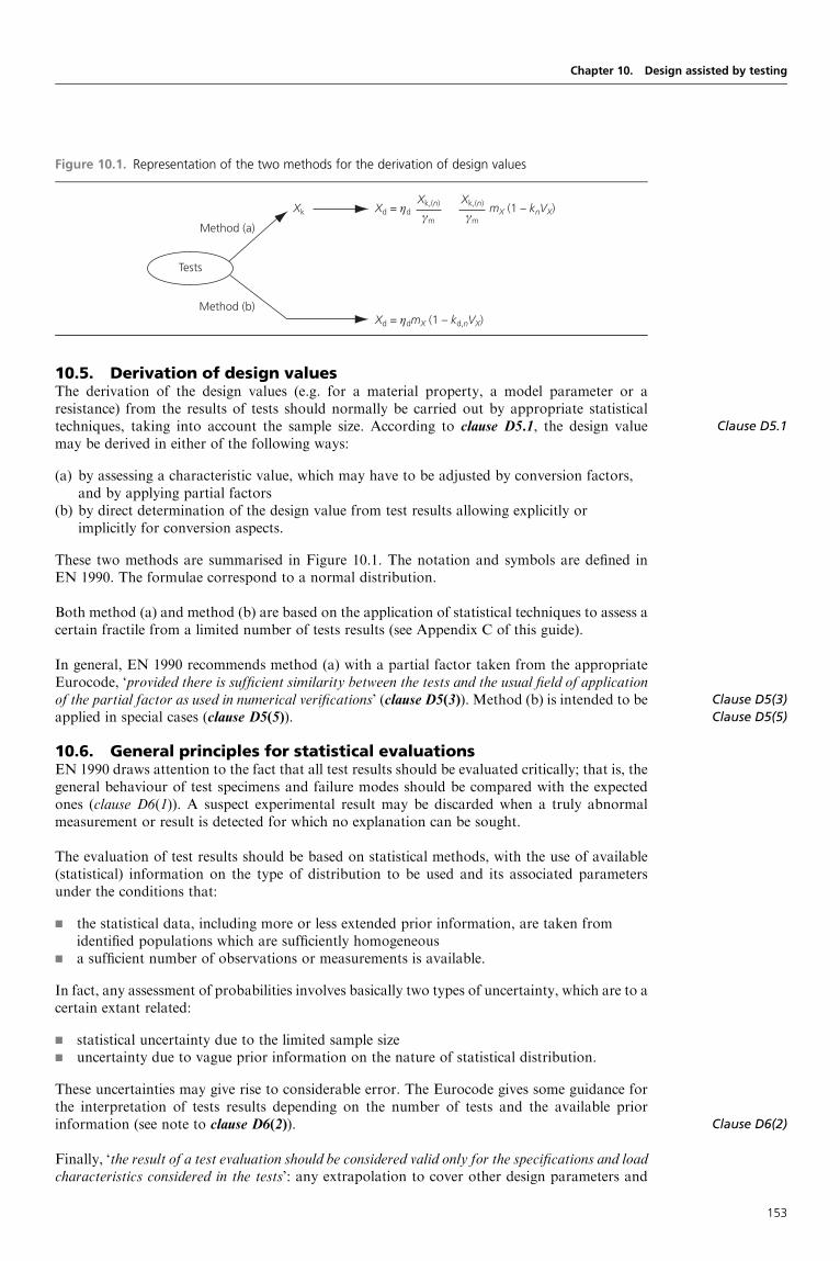
10.5. Derivation of design valuesThe derivation of the design values (e.g. for a material property, a model parameter or aresistance) from the results of tests should normally be carried out by appropriate statisticaltechniques, taking into account the sample size. According to clause D5.1, the design valuemay be derived in either of the following ways:
(a) by assessing a characteristic value, which may have to be adjusted by conversion factors,and by applying partial factors
(b) by direct determination of the design value from test results allowing explicitly orimplicitly for conversion aspects.
These two methods are summarised in Figure 10.1. The notation and symbols are defined inEN 1990. The formulae correspond to a normal distribution.
Both method (a) and method (b) are based on the application of statistical techniques to assess acertain fractile from a limited number of tests results (see Appendix C of this guide).
In general, EN 1990 recommends method (a) with a partial factor taken from the appropriateEurocode, ‘provided there is sufficient similarity between the tests and the usual field of applicationof the partial factor as used in numerical verifications’ (clause D5(3)). Method (b) is intended to beapplied in special cases (clause D5(5)).
10.6. General principles for statistical evaluationsEN 1990 draws attention to the fact that all test results should be evaluated critically; that is, thegeneral behaviour of test specimens and failure modes should be compared with the expectedones (clause D6(1)). A suspect experimental result may be discarded when a truly abnormalmeasurement or result is detected for which no explanation can be sought.
The evaluation of test results should be based on statistical methods, with the use of available(statistical) information on the type of distribution to be used and its associated parametersunder the conditions that:
g the statistical data, including more or less extended prior information, are taken fromidentified populations which are sufficiently homogeneous
g a sufficient number of observations or measurements is available.
In fact, any assessment of probabilities involves basically two types of uncertainty, which are to acertain extant related:
g statistical uncertainty due to the limited sample sizeg uncertainty due to vague prior information on the nature of statistical distribution.
These uncertainties may give rise to considerable error. The Eurocode gives some guidance forthe interpretation of tests results depending on the number of tests and the available priorinformation (see note to clause D6(2)).
Finally, ‘the result of a test evaluation should be considered valid only for the specifications and loadcharacteristics considered in the tests’: any extrapolation to cover other design parameters and
Clause D5.1
Clause D5(3)
Clause D5(5)
Clause D6(2)
Chapter 10. Design assisted by testing
Figure 10.1. Representation of the two methods for the derivation of design values
Tests
Method (a)
Method (b)Xd = ηdmX (1 – kd,nVX)
Xk,(n)
γm
Xk,(n)
γmXd = ηdXk mX (1 – knVX)
153

Clause D6(3)
Clause D7.1(1)–
Clause D7.1(4)
Clause D7.1(5)
Clause D7.2(1)
Clause D7.3(1)
Clause D3(1)
Clause D8.1(1)
loading should be made very cautiously, and if additional information from previous tests orfrom theoretical bases is available (clause D6(3)).
10.7. Statistical determination of a single property10.7.1 GeneralAs already stated, the design value of a single property X, which may represent a resistance of aproduct or a property contributing to the resistance of a product (e.g. a strength) may be assessedby either method (a) or (b) (clauses D7.1(1) to D7.1(4)).
Two tables in EN 1990 (Tables D1 andD2) give the values of the characteristic fractile factor (formethod (a)) and of the design fractile factor (for method (b)), and are based on the followingassumptions (clause D7.1(5)):
– all variables follow either a normal or a log-normal distribution;– there is no prior knowledge about the value of the mean;– for the case ‘‘VX unknown’’, there is no prior knowledge about the coefficient of variation;– for the case ‘‘VX known’’, there is full knowledge of the coefficient of variation.
In practice, EN 1990 recommends the use of ‘VX known’ together with a conservative upperestimate of VX, rather than applying the rules given for ‘VX unknown’. Moreover, VX, whenunknown, should be assumed to be no smaller than 0.10. In fact, the wording ‘VX known’ issomewhat ambiguous: what is ‘known’? It is assumed that, even if the mean value andstandard deviation are unknown, the coefficient of variation may be known: this means thatthe coefficient of variation may be correctly estimated by good engineering judgement andprofessional expertise; but it cannot be justified by mathematical considerations alone.
Formulae are given for a normal and a log-normal distribution. Adopting a log-normal distribu-tion for all variables has the advantage that no negative values can occur for the geometrical andresistance variables, which is physically correct.
10.7.2 Assessment via the characteristic valueFor method (a) the 5% fractile is usually assumed for the characteristic value, and the designvalue is assessed by using the formula (clause D7.2(1))
Xd ¼ �dXkðnÞ�m
¼ �d�m
mXð1� knVXÞ
kn is taken from Table D1 in EN 1990 (the origin of this table is given in Appendix C to thisguide).
10.7.3 Direct assessment of the design value for ULS verificationFor method (b), much lower probabilities, about 0.1% (corresponding to the product�R�¼ 0.8� 3.8¼ 3.04 (see Chapter 9)), are appropriate for the design value. Normally,method (b) would involve many more tests and so will be much more expensive than method(a). The design value is assessed by using the formula (clause D7.3(1))
Xd¼ �dmX(1� kd,nVX)
It should be noted that, is this case, �d includes all uncertainties not covered by the tests. kd,n istaken from Table D2 (the origin of this table is given in Appendix C to this guide).
10.8. Statistical determination of resistance models10.8.1 GeneralAfter the statistical evaluation of a single property, Annex D defines procedures for the statisticaldetermination of resistance models and procedures for deriving design values from tests oftype (d) (see clauses D3(1) and D8.1(1)).
Of course, a ‘design model’ has to be developed for the theoretical resistance rt of the memberor structural detail considered. It is assumed that this ‘design model’ would be adjusted until
Designers’ Guide to Eurocode: Basis of Structural Design
154

sufficient correlation is achieved between the theoretical values and the test data (clause D8.1(2)):this means, in particular, that, if the design model includes a hidden reliability margin, thismargin should be clearly identified when interpreting the test results. This question is discussedbelow. In the same way, deviation in the predictions obtained by using the design model shouldalso be determined from the tests (clause D8.1(3)). This deviation will need to be combined withthe deviations of the other variables (including deviations in material strength and stiffness, andgeometrical properties) in the resistance function in order to obtain an overall indication ofdeviation.
As for the determination of a single property, two different methods, (a) and (b), are distin-guished (clause D8.1(5)), based on seven steps: the first six steps are the same for bothmethods, and some assumptions regarding the test population are made and explained whichare to be considered as recommendations covering some of the more common cases.
10.8.2 Standard evaluation procedure (method (a))Annex D (clause D8.2.1) gives a standard procedure for the assessment of a characteristic valuebased on the following assumptions:
a) the resistance function is a function of a number of independent variables X;b) a sufficient number of test results is available;c) all relevant geometrical and material properties are measured;d ) there is no correlation (statistical dependence) between the variables in the resistance
function;e) all variables follow either a Normal or a log-normal distribution.
This procedure is detailed in clauses D8.2.2.1 to D8.2.2.7. The procedure is presented inTable 10.2, and illustrated by an example. The selected example is the resistance function forbolts in bearing. Some additional comments follow the table.
Clause D8.1(2)
Clause D8.1(3)
Clause D8.1(5)
Clause D8.2.1
Clause D8.2.2.1–
Clause D8.2.2.7
Clause D8.2.2.1
Clause D8.2.2.2
Chapter 10. Design assisted by testing
Table 10.2. Standard evaluation procedure: method (a)
Steps Example
Step 1
Develop a design model (clause D8.2.2.1)
rt¼ grt(X)
X the vector of basic variables
For bolts in bearing (e1� 3d0):
rt¼ 2.5dtfu
Step 2
Compare theoretical and experimental values
(clause D8.2.2.2):
Plot re against rt
θ
rt
re re = b(r)rt
The causes of any systematic deviation from the
line �¼/4 should be investigated to check
whether this indicates errors in the test
procedures or in the resistance function
For bolt i:
rti¼ 2.5ditifui
155

Clause D8.2.2.3
Clause D8.2.2.4
Clause D8.2.2.5
Clause D8.2.2.6
Designers’ Guide to Eurocode: Basis of Structural Design
Table 10.2. Continued
Steps Example
Step 3
Estimate the mean value correction factor b
(clause D8.2.2.3):
Corrected resistance: r¼ brt�
Calculate: b ¼P
rertPr2t
rm¼ brt(Xm)�¼ bgrt(Xm)�
For the example, it is assumed that b¼ 1:
rtm ¼ bgrtðmÞ� ¼ 2:5dmtmfum
Step 4
Estimate the coefficient of variation V� of the
errors (clause D8.2.2.4):
Calculate: �i ¼reibrti
�i ¼ lnð�iÞ
��� ¼ 1
n
Xni ¼ 1
�i
s2� ¼ 1
n� 1
Xni ¼ 1
ð�i � ���Þ2
V� ¼ffiffiffiffiffiffiffiffiffiffiffiffiffiffiffiffiffiffiffiffiffiffiffiffiffiexpðs2�Þ � 1
q
For the example, it is assumed that V�¼ 0.08
Step 5
Analyse compatibility of the test population
(clause D8.8.2.5)
As an illustration, the results of shear tests on bolts are
shown in the figure below, split into subsets according
to the bolt grade. Clearly in this case the resistance
function can be improved if the coefficient 0.7 in the
resistance function is replaced by a function of the bolt
strength fub
1.4
1.2
1.0
0.8
0.6
re
rt
4.6 5.6 8.8 10.9Bolt grade
r = 0.7Afub
Shear failure of bolts with the shear in the threaded portion
Step 6
Determine the coefficients of variation VXi of
the basic variables (clause D8.8.2.6)
For the resistance function considered for the bearing
resistance of bolts, the following values of the
coefficients of variation have been determined from
studies on the variability of bolt dimensions and material
properties:
Vd¼ 0.005
Vt¼ 0.05
Vfu¼ 0.07
156

The following symbols are used:
d0 nominal hole diameter fui ultimate tensile strength of plate idi diameter of bolt i fu ultimate tensile strength of the bolte1 end distance ti thickness of plate i
Step 1No additional comment.
Chapter 10. Design assisted by testing
Table 10.2. Continued
Steps Example
Step 7
Determine the characteristic value rk of the
resistance:
r¼ brt�¼ b(X1�X2� . . .�Xj)�
Mean value:
E(r)¼ b[E(X1)� E(X2)� . . .� E(Xj)]�¼ bgrt(Xm)
Coefficient of variation:
V2r ¼ ðV2
� þ 1Þ Qji ¼ 1
ðV2Xi þ 1
!� 1
For small values of V�2 and V 2
Xi:
Vr2 V�
2þ Vrt2
with
V2rt ¼
Pji ¼ 1
V2Xi
For the example:
grt(Xm)¼ 2.5dmtmfumffiffiffiffiffiffiffiffiffiffiffiffiffiffiffiffiffiffiffiffiffiffiffiffiffiffiffiffiffiV2d þ V2
t þ V2fu
q¼
ffiffiffiffiffiffiffiffiffiffiffiffiffiffiffiffiffiffiffiffiffiffiffiffiffiffiffiffiffiffiffiffiffiffiffiffiffiffiffiffiffiffiffiffiffiffiffiffiffi0:0052 þ 0:052 þ 0:072
p¼ 0:086
Vr ¼ffiffiffiffiffiffiffiffiffiffiffiffiffiffiffiffiffiV2rt þ V2
�
q¼
ffiffiffiffiffiffiffiffiffiffiffiffiffiffiffiffiffiffiffiffiffiffiffiffiffiffiffiffiffiffiffiffi0:0862 þ 0:082
p¼ 0:118
For a limited number of tests
rk¼ bgrt(Xm) exp(�k1�rtQrt� kna�Q�� 0.5Q2)
where
Qrt ¼ �lnðrtÞ ¼ffiffiffiffiffiffiffiffiffiffiffiffiffiffiffiffiffiffiffiffiffiffilnðV2
rt þ 1Þq
Q� ¼ �lnð�Þ ¼ffiffiffiffiffiffiffiffiffiffiffiffiffiffiffiffiffiffiffiffiffiffilnðV2
rt þ 1Þq
Qr ¼ �lnðrÞ ¼ffiffiffiffiffiffiffiffiffiffiffiffiffiffiffiffiffiffiffiffiffiffilnðV2
r þ 1Þq
�rt ¼Qrt
Q
�� ¼Q�
Qr
kn is the characteristic fractile factor from
Table D1 for VX unknown
k1 is the value of kn for n ! 1(k1¼ 1.64)
�rt is the weighting factor for Qrt
�� is the weighting factor for Q�
For a large number of tests:
rk¼ bgrt(Xm) exp(�k1Q� 0.5Q2)
For a large number of tests:
Q Vr
rk¼ rtm exp(�1.64� 0.118 � 0.5� 0.1182)
rk¼ rtm� 0.818
157

Step 2The Eurocode is perhaps too restrictive when a systematic deviation from the line �¼ /4appears. In some cases, and more particularly for prefabricated concrete members, the resistancefunction may include reliability margins. For example, Figure 10.2 shows the experimental valuesof the shear resistance of reinforced concrete beams compared with the design values assessedfrom Eurocode 2. This figure shows a systematic deviation from the line �¼ /4.
Step 3No additional comment.
Step 4No additional comment.
Step 5It is often found that the frequency distribution for resistance from tests cannot be described by aunimodal function, because it represents two or more subsets which result in a bimodal or multi-modal function. This can be checked by plotting on Gaussian paper or by using appropriatesoftware. When plotted with the horizontal axis as a linear scale, a unimodal function shouldgive a straight line (if normally distributed) or a monotonically curved line (if log-normal). Itis more convenient to plot log-normally distributed functions with a logarithmic horizontalaxis, because this gives a linear plot.
If no other way is found to separate the subsets, a unimodal function can be extracted frombimodal or multimodal functions using appropriate procedures. The statistical data for theunimodal function can be taken from a tangent to the actual distribution. Thus, bm(r) andsmb(r) are obtained instead of b(r) and sb(r), and hence sm�(r) instead of s�(r). The evaluationprocedure for unimodal functions described hereafter can then be used.
Commonly, it is difficult to construct a representative tangent, in which case a linear regression ofthe lower end of the data can be carried out and the regression line used in place of the tangent.Generally, it is advisable to use at least 20 data points for this regression.
Step 6No additional comment.
Step 7No additional comment.
Designers’ Guide to Eurocode: Basis of Structural Design
Figure 10.2. Comparison between experimental and design shear resistance: reinforced concrete beams
with shear reinforcement (167 tests)
0 200 400 600 800 1000 1200 1400 16000
Design value: kN
1600
1400
1200
800
600
400
200
1000
Expe
rimen
tal v
alue
: kN
Mean = 1.67Standard deviation = 0.696Coefficient of variation = 41.69%
158

10.8.3 Standard evaluation procedure (method (b))This procedure is given to derive directly from tests the design value rd of a resistance. It followssteps 1 to 6 as previously defined and, for step 7, the characteristic fractile factor kn is replaced bythe design fractile factor kd,n equal to the product �R� assessed at 0.8� 3.8¼ 3.04. Thus, the lastrow of Table 10.2 is replaced by that in Table 10.3.
10.8.4 Use of additional prior knowledgeThis final section may be the most controversial: it develops an aspect of probabilistic interpreta-tion of data which can be done only by experts. However, the assumptions are very important:
g the validity of the resistance function rtg an upper bound (conservative estimate) for the coefficient of variation Vr are already
known from a significant number of previous tests.
Then, the characteristic value rk may be determined from the result re of only one further testusing the formula
rk¼ �kre
where �k¼ 0.9 exp(�2.31Vr� 0.5Vr2), and Vr is the maximum coefficient of variation observed in
previous tests.
If two or three further tests are carried out, the characteristic value rk may be determined from themean value rem of the test results using the formula
rk¼ �krem
where
�k¼ exp(�2.0Vr� 0.5Vr2)
and Vr is the maximum coefficient of variation observed in previous tests, provided that eachextreme (maximum or minimum) value ree satisfies the condition
|ree� rem|� 0.10rem
Clause D8.3
Chapter 10. Design assisted by testing
Table 10.3. Standard evaluation procedure: method (b)
Steps Example
Steps 1 to 6
As Table 10.2
Step 7
Determine the design value rd of the resistance
(clause D8.3)
For a limited number of tests:
rd¼ bgrt(Xm) exp(�kd,1�rtQrt� kd,na�Q�� 0.5Q2)
where
kd,n is the design fractile factor from Table D2
for VX unknown
kd,1 is the value of kd,n for n ! 1 (kd,1¼ 3.04)
For a large number of tests:
rd¼ bgrt(Xm) exp(�kd,1Q� 0.5Q2)
For the example, and a large number of tests:
�R¼ exp[(3.04� 1.64)Q]
¼ exp(1.40� 0.118)
¼ 1.18
159

FURTHER READING
Ang AHS and Tang WH (1984) Probability Concepts in Engineering. Planning and Design, vols I
and II. Wiley, Chichester.
Augusti G, Baratta A and Casciati F (1984) Probabilistic Methods in Structural Engineering.
Chapman and Hall, London.
Benjamin JR and Cornell CA (1970) Probability, Statistics and Decisions for Civil Engineers.
McGraw-Hill, New York.
Bolotin VV (1969) Statistical Methods in Structural Mechanics. Holden-Day, San Francisco, CA.
Borges JF and Castanheta M (1985) Structural Safety. Laboratorio Nacional de Engenharia Civil,
Lisbon.
Construction Industry Research and Information Association (1977) Rationalisation of Safety and
Serviceability Factors in Structural Codes. CIRIA, London. Report 63.
Ditlevsen O (1981) Uncertainty Modelling. McGraw-Hill, New York.
Ditlevsen O and Madsen HO (1996) Structural Reliability Methods. Wiley, Chichester.
Euro-International Concrete Commission (1976) Common Unified Rules for Different Types of
Construction and Materials, vol. 1. FIB, Lausanne. CEB Bulletin 116.
Euro-International Concrete Commission (1976) First Order Concepts for Design Codes. FIB,
Lausanne. CEB Bulletin 112.
ISO (1998) ISO 2394. General principles on reliability for structures. ISO, Geneva.
Madsen HO, Krenk S and Lind NC (1986) Methods of Structural Safety. Prentice-Hall, Englewood
Cliffs, NJ.
Melchers RE (1999) Structural Reliability: Analysis and Prediction. Wiley, Chichester.
Thoft-Christensen P and Baker MJ (1982) Structural Reliability Theory and its Applications.
Springer-Verlag, Berlin.
Thoft-Christensen P and Murotsu Y (1986) Application of Structural Systems Reliability Theory.
Springer-Verlag, Berlin.
Designers’ Guide to Eurocode: Basis of Structural Design
160

Designers’ Guide to Eurocode: Basis of Structural DesignISBN 978-0-7277-4171-4
ICE Publishing: All rights reserved
http://dx.doi.org/10.1680/bsd.41714.161
Appendix A
The Construction Products Directive(89/106/EEC)
As compliance to the structural Eurocodes will satisfy the requirement of the ConstructionProducts Directive in respect of mechanical resistance, this appendix provides a shortintroduction to the Construction Products Directive (Directive 89/106/EEC), the essentialrequirements contained in the Directive and the Interpretative Document to the first essentialrequirement, ‘Mechanical resistance and stability’.
NoteThe following abbreviations are used in this appendix:
CEC Commission of the European CommunitiesCEN European Committee for StandardizationCPD Construction Products DirectiveEN European StandardID Interpretative Document
Compliance with the structural Eurocodes and the ConstructionProduct DirectiveCompliance with the structural Eurocodes will satisfy the essential requirement of the CPD inrespect to ‘Mechanical resistance and stability’, and part of ‘Safety in case of fire’.
The Construction Products DirectiveA major objective of the CEC is the removal of barriers to trade across national borders and toimplement the European internal market. This market is characterised by the free movement ofgoods, services, capital and people. To realise this objective, approximation (i.e. harmonisation)of laws, regulations and administrative provisions for EU member states is necessary. The CPD,relating to construction products, which was adopted by the CEC on 21 December 1988, is animportant element of this approximation process. The CPD has been transferred into nationallaw by the majority of EU member states.
The main objective of the CPD is to provide a legal basis for the attestation of conformity (seeFigure A.1) so that free movement of the relevant product is ensured.
The scope of the CPD is construction products which are defined as products that are producedfor incorporation in a permanent manner in construction works, including both building andcivil engineering works, in so far as the essential requirements relate to them.
The essential requirementsThe essential requirements apply to construction works, not to construction products as such,but they will influence the technical characteristics of these products.
Thus, construction products must be suitable for construction works which, as a whole and intheir separate parts, are fit for their intended use, account being taken of economy, and whichsatisfy the essential requirements where the works are subject to regulations containing suchrequirements.
161

The essential requirements relate to:
g mechanical resistance and stabilityg safety in case of fireg hygiene, health and environmentg safety in useg protection against noiseg energy economy and heat retention.
These requirements must, subject to normal maintenance, be satisfied for an economicallyreasonable working life.
The essential requirements may give rise to the establishment of classes of a constructionproduct corresponding to different performance levels, to take account of possible differencesin geographical or climatic conditions or in ways of life as well as different levels of protectionthat may prevail at national, regional or local level. EU member states may require performancelevels to be observed in their territory only within the classification thus established.
The structural Eurocodes relate to the essential requirement for ‘Mechanical resistance andstability’, which states:
a) collapse of the whole or part of the work;b) major deformations to an inadmissible degree;c) damage to other parts of the works or to fittings or installed equipment as a result of
major deformation of the load bearing construction;d) damage by an event to an extent disproportionate to the original cause.
The structural Eurocodes also relate to part of the essential requirements for safety in case offire. The essential requirements are given concrete (i.e. quantitative) form in interpretative
Designers’ Guide to Eurocode: Basis of Structural Design
Figure A.1. The European system for the approximation of laws, regulation and administrative provisions
relating to construction products
Construction Product Directive sets out essential requirements
Interpretative documents
Mandates
Attestation of conformity
Technical specifications
European harmonized standards
Category A
Design andexecution
Category B
Productstandards
European technical approval
Guidelines forEuropean technical approval
162

documents, which will create the necessary links between those requirements and, for example,the mandates to draw up European standards for particular construction products (seeFigure A.1). Interpretative Documents for each of the six essential requirements are available.ID 1 refers to ‘Mechanical resistance and stability’.
Methods of satisfying the essential requirementsIn practice, a product is fit for the intended use when it permits the works in which it is incorpo-rated to satisfy the applicable essential requirements; a product is presumed to be fit for itsintended use if it bears the EC marking (Figure A.2), which declares the conformity of theproduct to technical specifications (see Figure A.1). These specifications comprise:
g Harmonised standards (Article 7 of the CPD) established by the CEN on the basis ofmandates
g European technical approval (Article 8 of the CPD). Favourable technical assessment ofthe fitness for use of a product for an intended use, based on the fulfilment of the essentialrequirements for construction works for which the product is used.
Article 4 of the CPD allows referencing to national standards, but only where harmonisedEuropean specifications do not exist.
ID 1: Mechanical resistance and stabilityWith regard to the design of structures, ID 1 provides:
g a definition of the general terms used in all the Interpretative Documentsg a precise definition of the essential requirement ‘Mechanical Resistance and Stability’g the basis for the verification of satisfaction of the requirement ‘Mechanical Resistance and
Stability’.
With regard to the verification along with other rules, ID 1 states in clause 3.1(3):
The satisfaction of the essential requirements is assured by a number of interrelatedmeasures concerned in particular with;
– the planning and design of the works, the execution of the works and necessarymaintenance;
– the properties, performance and use of the construction products.
Thus, considering the above subclause, ID 1 distinguishes between the design of the buildings andcivil engineering works as a whole and the technical properties of the construction productsthemselves. In Clause 4 of ID 1, design and product standards are defined as follows:
– Category A: These are standards, which concern the design and execution of buildings andcivil engineering works and their parts, or particular aspects thereof, with a view to thefulfilment of the essential requirements as set out in the Council Directive 89/106/EEC.
Category A standards should be taken into consideration within the scope of the Directiveas far as differences in laws, regulations and administrative provisions of Member Statesprevent the development of harmonised product standards.
– Category B: These are technical specifications and guidelines for European technicalapproval which exclusively concern construction products subject to an attestation ofconformity and marking according to Articles 13, 14 and 15 of the Council Directive
Clause 3.1(3)
Appendix A. The Construction Products Directive (89/106/EEC)
Figure A.2. The EC mark, signifying a product complies with the relevant standard or technical approval
CommunautéEuropéene
EuropeanCommunity
163

89/106/EEC. They concern requirements with regard to performance and/or otherproperties including durability of those characteristics that may influence the fulfilment ofthe essential requirements, testing, compliance criteria of a product.
Category B standards that concern a family of products, or several families of products areof different character and are called horizontal (Category B) standards.
ID 1 further states:
The assumptions made in Category A standards on the one side and those made inCategory B specifications on the other side shall be compatible to each other.
Category A standardsThe structural Eurocodes are considered as one group of Category A standards.
Designers’ Guide to Eurocode: Basis of Structural Design
164

This page has been reformatted by Knovel to provide easier navigation.
INDEX
Index Terms Links
A
accident 8 15 20
21 23 24
35 121
accidental actions 41 42 44
46–47
area of risk of collapse in event of an accident, illustration 22
combinations of actions for accidental design situations 83
design values of actions in accidental design situations 100
actions 41–50 64–67 69
97
accidental actions 41 42 44
46–47 100
actions on structures, Eurocode 1 165
characteristic values of actions 43–47 111
classifications of actions 41–43
combination of actions 80–84 84–85 87–89
100 101 102–103
111–113 141
bridge deck built by cantilever method, illustration 81
combinations of actions for accidental design situations 83
combinations of actions for seismic design situations 83–84
example of continuous beam, illustration 80
design values of actions 70–71 90 91
93
design values of actions in accidental and seismic design
situations 100
design values of actions in persistent and transient design
situations 89–91
design values of actions transmitted to footing, table 111
design values of effects of actions 71–73
partial factors, application of actions and, table 109
partial factors for actions and combinations of actions 84 101
permanent actions 41 42 44–45
72 82 89
90 91 92
93 94 95

Index Terms Links
This page has been reformatted by Knovel to provide easier navigation.
actions
permanent actions (Cont.)
100 101 104
105 110 111
113
illustration 45
variable actions 41 42 43
45–46 47–49 72
82 87 88
89 90 91
94 104 105
108 110 111–113
114 130
illustrations 46 49 112
113
tables 47 48 100
101 140
see also dynamic actions; favourable/unfavourable actions;
geotechnical actions; static actions
AFNOR 5 182
airport buildings 36
aluminium 3 166
anchors 45 79 98
105 106 107
108 109 110
Annex A 69 77 82
84
Annex Al 87–118
Annex A2 107
Annex B 23 119 120
122 124 125
126
Annex C 40 70 119
129 130 135
Annex D 57 67 69–70
76 151 152
154
application, field of 5
Annex Al 87
design assisted by testing 151
partial factor design and reliability analysis 129
reliability 119

Index Terms Links
This page has been reformatted by Knovel to provide easier navigation.
Application and Use of Eurocodes 1 4 13
Application Rules 63 66 70
87
distinction between principles and 11 13–14
assumptions 11 12–13
Austria 181
avalanches 35
B
basement walls 76 77 96
Basic Notes on Model Uncertainties 96
basic requirements 19–23
Bayesian method 175–176 179
beams 34 38 63
64 65 75
79 80 81
96 103 104
108–110 111 112
113 125 158
bearing condition 36 37
bearing walls 102 103
Belgium 181
benefits of use of Eurocodes 4
bollards 36
Borges-Castanheta model 141
bridges 23 26 41
42 44 77
81 107 120
122 124 165
166
example of accidental impact on a bridge deck, illustration 24
footbridges 104
vibration of footbridges 34–35
railway bridges 34 43 84
road bridges 45 47
river bridges 35
BS 5950 94 96
BS 8110 94 96
BSI 5
BSI 1978 21 22
BSI 1985a,b 21 22
BSI 1990 21 22

Index Terms Links
This page has been reformatted by Knovel to provide easier navigation.
buckling 64 65 75
Building Regulations, UK 6 12 20
Bulgaria 181
C
cantilevers 22 79 81
97 103 104
108–110
CEB 94 96 116
117 120 123
CEC 1 2 161
ceilings 102
CEN 1 2 3
4 5 8
29 89 126
163 181–184
Central Europe 100
chlorides 26
CIB 120
classification 24–25
classification of actions 41–43
classification depending on origin 41 42
classification depending on the nature and or the structural
response 43
classification depending on variation in space 41 42
classification depending on variation in time 41–42
practical examples 42–43
table 42
clause 1.1 12
clause 1.3 12
clause 1.4 13 14
clause 1.5 14 15–16 33
35 36 38
39 41
clause 2.1 19 20–21 23
26 34
clause 2.2 19 23–25
clause 2.3 19 28
clause 2.4 19 27–28 29
clause 2.5 19 29
clause 3.1 33 34 35
clause 3.2 33 35 36

Index Terms Links
This page has been reformatted by Knovel to provide easier navigation.
clause 3.3 33 36 39
clause 3.4 33 38 39
clause 3.5 33 39 40
clause 4.1 41 42–50
clause 4.2 41 50–51
clause 4.3 41 52
clause 5.1 63–67
clause 5.2 63 67–68
clause 6.1 69–70
clause 6.2 69 70
clause 6.3 69 71–76
clause 6.4 38 69 76–84
92 104
clause 6.5 69 84–85
clause Al. 1 26 87 88
clause A1.2 87–88 91 113
table of recommended values 88 89
clause A1.3 87 89–91 92
100
clause Al.4 87 102 104
clause Bl 119
clause B2 119–120
clause B3 119 122 124
clause B4 119 125–126
clause B5 119 126
clause B6 119 128
clause CI 129
clause C2 129
clause C3 129 130
clause C4 129 130
clause C5 129 130
clause C6 129 130 134
clause C7 129 134–138
clause C8 129 138–139
clause C9 129 139
clause C10 129 140
clause Dl 151
clause D2 151
clause D3 151
clause D4 151
clause D5 151 153
clause D6 151 153–154

Index Terms Links
This page has been reformatted by Knovel to provide easier navigation.
clause D7 151 154
clause D8 151 152 154–155
columns 61 62 64
75 81 107
125
concrete 3 7 8
23 27 31
34 38 51
57 65 73
79 81 85
95 96 125
127 158 165–166
174 178
Construction Products Directive (CPD) 1 2 4–5
161–164
Category A standards 164
ID 1 163–164
objectives of 161
European system for approximation of laws, regulation
and administrative provisions, illustration 162
requirements of 161–163
requirements, methods of satisfying the 163
EC mark, illustration 163
Construction Products Regulation (CPR) 4
contents of Eurocode programme 3
corrosion 26 28 29
76 87
CPD see Construction Products Directive
CPR see Construction Products Regulation
cracks 27 37 38
39 54 85
102
cranes 42 64 102
103 165
creep 26 42 49
54 58 85
104
Croatia 181
Cyprus 181

Index Terms Links
This page has been reformatted by Knovel to provide easier navigation.
D
definitions 11 14–15
alphabetical index of 15–16
deflection 33 34 37
38 102 103
117
deformation 21 39 64
65 76 78
79 99 102–104
Denmark 182
Department of Environment, UK 21 22
design, complete Eurocode suite 165–166
design, fire 67 166
design, partial factor, and reliability analysis 129–150
design, principles of limit states 33–40
design situations 33 35–36
irreversible and reversible limit states, illustration 38
limit state design 33 39–40
serviceability limit states 33 34 38–39
sharp and vague definitions of a limit state, illustration 34
ultimate limit states 33 34 36–38
see also limit state design; serviceability limit state; ultimate
limit state
design assisted by testing 67–68 151–160
design model, description of a 154–155
design resistance 75–76
design situations, combinations of actions for accidental 83
design situations, combination of actions for seismic 83–84
design supervision differentiation 119 125–126 127
design values 69 70–76 89–91
93 94 97
100 101 105
107 110 111
121
application of model factor in case of non-linear analysis,
illustration 74
application of partial factor, illustration 73
application of permanent and variable actions,
illustrations 72
calibration of design values, partial factor design and
reliability analysis 129 134–138

Index Terms Links
This page has been reformatted by Knovel to provide easier navigation.
design values (Cont.)
derivation of design values, design assisted by testing 151 153
representation of two methods for derivation of design
values, illustration 153
design values of actions (EQU) (set A) (Table A1.2(A) of
EN1990), table 89
design values of actions (STR/GEO) (set B) (Table A1.2(B)
of EN 1990) 90
design values of actions (STR/GEO) (set C) (Table A1.2(C)
of EN 1990) 91
general overview of partial factor system, illustration 70
limit states and sets of design values, illustration 91
design working life 19 25–27 87
134
indicative working life, table 26
differentiation, design supervision 119 125–126
design supervision levels, table 126
examples of design supervision levels for activities, table 127
differentiation, reliability 119 120–125
background 120–121 125
consequence clauses 120–122
differentiation by β values 122–124
displacement 21 39 65
78 102 103
illustration 124
tables 122 123
measures relating to partial factors 124–125
DIN 5 182
drainage 28 102 103
durability 2 4 7
19 20 26
27–29
evolution with time of a structure, illustration 27
dynamic actions 43 49 65–66
illustration 66
E
earthquakes see seismic situations
economic losses 24 25 122
ENs 6–7 43
EN 1991 3 14 79
84
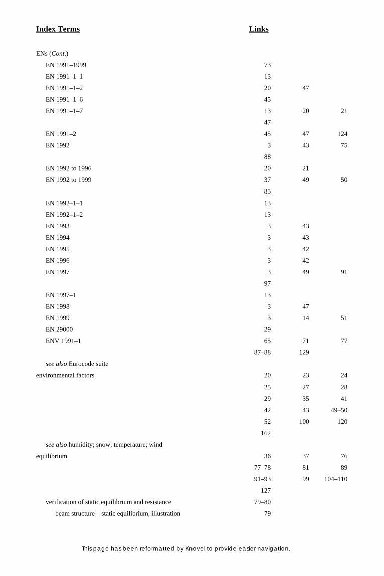
Index Terms Links
This page has been reformatted by Knovel to provide easier navigation.
ENs (Cont.)
EN 1991–1999 73
EN 1991–1–1 13
EN 1991–1–2 20 47
EN 1991–1–6 45
EN 1991–1–7 13 20 21
47
EN 1991–2 45 47 124
EN 1992 3 43 75
88
EN 1992 to 1996 20 21
EN 1992 to 1999 37 49 50
85
EN 1992–1–1 13
EN 1992–1–2 13
EN 1993 3 43
EN 1994 3 43
EN 1995 3 42
EN 1996 3 42
EN 1997 3 49 91
97
EN 1997–1 13
EN 1998 3 47
EN 1999 3 14 51
EN 29000 29
ENV 1991–1 65 71 77
87–88 129
see also Eurocode suite
environmental factors 20 23 24
25 27 28
29 35 41
42 43 49–50
52 100 120
162
see also humidity; snow; temperature; wind
equilibrium 36 37 76
77–78 81 89
91–93 99 104–110
127
verification of static equilibrium and resistance 79–80
beam structure – static equilibrium, illustration 79

Index Terms Links
This page has been reformatted by Knovel to provide easier navigation.
error 14 19 20
21 23 25
56 57 119
123 125 153
155 156
ERs 1 4 5
Estonia 182
ETA 1–2 4 6–7
ETAGs 7 13
Eurocode suite 165–166
Eurocode 1 165
Eurocode 2 8 165
Eurocode 3 165
Eurocode 4 165–166
Eurocode 5 166
Eurocode 6 166
Eurocode 7 71 76 166
Eurocode 9 166
Eurocodes 1 to 9 75 85 101
Eurocodes 2 to 9 75 79 84
Europe, earthquakes in 43
European technical approval 163–164
explosions 5 19 20
41 42 47
83 100 165
F
fatigue 26 37–38 43
49 54 76
79 87 91
101 136 165
favourable/unfavourable actions 72 82 83
89 90 91
92 93 94
100 101 104
105 114 124
finite-element analysis 72 76 152
Finland 89 182
fire 2 3 8
11 15 19
41 42 83
100 121 165

Index Terms Links
This page has been reformatted by Knovel to provide easier navigation.
fire (Cont.)
design 67 166
requirements in the case of 20
safety in case of 4 5 161
162
floors 41 45 61
80 94 101
102 114 115
126
footbridges 34–35 104
footing 76 77 78
96 110 111
FORM 135 136
foundation, spread see spread foundation, example of
fractiles, estimation of 173–179
Bayesian method 175–176 179
comparison of coverage and prediction methods 176–177
tables 176 177
coverage method 174–175 176–177
example 178–179
method of order 174
prediction method 175 176–177
use of three-parameter log-normal distribution 177–178
illustration 178
tables 177
framed structure, STR limit states in see limit states STR in
framed structure
France 5 182
G
Gaussian distribution 44
Gaussian paper 158
geometrical data 52 58–60 130
design values of 74–75
illustrations 59 60
geotechnical actions 49 90 91
93 96–97 99
illustrative example 97
see also limit states GEO; limit states STR/GEO
geotechnical design 3 76 91
97 166
geotechnical problems 71 72 78

Index Terms Links
This page has been reformatted by Knovel to provide easier navigation.
geotechnical resistance 91
Germany 5 182
Greece 182
greenhouse 69
Guidance Paper L 1
Gumbel distribution 141 148 149
H
hangers 132 133 136
137 142 145
hazard 5 13 14
16 21 35
78 121 126
hEN 1 4
Holicky and Vorlicek 174
Horizontal Group (HG) 3
humidity 28 43 49
52 54
Hungary 182
hydraulic heave 91
I
Iceland 89
impact 19 20 21
23 24 35
36 41 42
43 47 83
100 122 165
imposed loads 89 94 95
113 114 115
116 165
inspection during execution 126–128
inspection classes, table 127
inspection levels, table 126
see also supervision
Interpretive Documents (IDs) 1 4–5
ID 1 163–164
Ireland 182
ISO 2394 14 15 129
141 174 175
ISO 2631 117
ISO 3898 15

Index Terms Links
This page has been reformatted by Knovel to provide easier navigation.
ISO 8930 14
ISO 9000 29
ISO 9004 29
ISO 10133 116
ISO 12491 171 172 173
175
ISO/DIS 5479 171
Italy 5 183
L
Latvia 183
layout of EN 1990 7
limit states, illustrative example 92
limit states, reversible 102 103
limit states and design values, table 91
limit states design 33–40 64 120–121
see also serviceability limit state; ultimate limit state
limit states EQU 77–78 91–93 99
104–110
limit states FAT 79 91
limit states GEO 78–79 82 83
85 91 92
99 110
limit states HYD 91
limit states STR 78 82 83
85 91 92
93–96 99
limit states STR in framed structure 113–116
limit states STR/GEO 90 91 96–98
104–110
limit states UPL 91
limitations 69 70
links between Eurocodes, illustration 12
Lithuania 183
log-normal distribution 48 54–56 154
169–171
with the lower bound at zero 56–57
illustration 56
use of three-parameter log-normal distribution 177–178

Index Terms Links
This page has been reformatted by Knovel to provide easier navigation.
M
maintenance 13 15 16
25 26 27
28–29 30 31
35 63 119
162 163
masonry 3 21 31
42 166
material properties 50–51 97 127
156
characteristic values 50 54–58
design values of material properties 73–74
determination of characteristic values 50–51
illustrations 50 51 53
55 56
modelling of material properties 50 52–54
partial factors for 84 85 128
materials, choice of 28
Mathcad sheets 129 134 137
144–149
mechanical resistance and stability 161 162 163–164
166
Mediterranean 100
modelling 8 11 13
25 29 39
41 42 43
49 50 51
68 71 97
152 153 168
171 178
dynamic actions 65–66
fire design 67
material properties 50 52–54
static actions 64–65
statistical determination of resistance models 151 154–159
structural modelling 16 63–64
multi-storey buildings 21–22
area of risk of collapse in the event of accident, illustration 22

Index Terms Links
This page has been reformatted by Knovel to provide easier navigation.
N
National Annexes 2 5 6
9 26 82
83 84 88
89 90 91
92 93 96
102 105 125
see also Annex A to D
National Competent Authority 20 21
National Foreword 5
National Provisions 2 13
National Title Page 5
national standard organisations 181–184
national standards implementing Eurocodes 5–6
illustration 5
normal distribution 44 45 54–56
169–171
illustration 55
normality tests 170–171
standardised variables 170
table 170
normative references 11 12
Norway 89 183
O
objectives of Eurocode programme 2–3
see also technical objectives of EN 1990
occupations 121
organisation of EN 1990 7
organisation of the Eurocode work, illustration 3
P
partial factor design and reliability analysis 129–150
partial factors in EN 1990 129 139–140
relationship between individual partial factors,
illustration 140
partial factors 69–85 98 99
101 104 105
110 111 112
113 120 124–125
128

Index Terms Links
This page has been reformatted by Knovel to provide easier navigation.
partition walls 63 102 103
permanent actions 41 42 44–45
72 82 83
89 90 91
92 93 94
95 100 101
104 105 111
113
persistent situations 35 47 89–91
PFI 128
piles 26 76 77
96 98
plasticity 64
Poisson ratio 53
Poland 183
populations and samples, statistics 167–169 176
basics 167
population parameters 168–169 171
sample characteristics 167–168
Portal 62
principle requirements of EN 1990 19 20
Principles, distinction between Application Rules and 13–14 63 66
product properties
design values of 73–74
partial factors for 84
Q
quality management 19 29–31 125
construction works process life cycle 30
construction process and quality, table 31
quality loop for buildings, illustration 30
policy 29–30 30–31
R
railways 34 43 84
121
Rankine’s theory 97
reference period, concept of 46
reliability 19 20 23–25
37 69 94–96
105 119–128
basic concepts 23–24
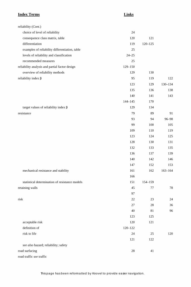
Index Terms Links
This page has been reformatted by Knovel to provide easier navigation.
reliability (Cont.)
choice of level of reliability 24
consequence class matrix, table 120 121
differentiation 119 120–125
examples of reliability differentiation, table 25
levels of reliability and classification 24–25
recommended measures 25
reliability analysis and partial factor design 129–150
overview of reliability methods 129 130
reliability index β 95 119 122
123 129 130–134
135 136 138
140 141 143
144–145 170
target values of reliability index β 129 134
resistance 79 89 91
93 94 96–98
99 100 105
109 110 119
123 124 125
128 130 131
132 133 135
136 137 139
140 142 146
147 152 153
mechanical resistance and stability 161 162 163–164
166
statistical determination of resistance models 151 154–159
retaining walls 45 77 78
97
risk 22 23 24
27 28 36
40 81 96
123 125
acceptable risk 120 121
definition of 120–122
risk to life 24 25 120
121 122
see also hazard; reliability; safety
road surfacing 28 41
road traffic see traffic

Index Terms Links
This page has been reformatted by Knovel to provide easier navigation.
robustness 19 20–21 25
37 125
rock 35 50 76
77 78
Romania 183
roofs 102 114 115
116
roofs with large clear span between supports 22–23
illustration of acceptable extent of collapse in event of local
failure 23
rupture 36 53 54
79
S
safe-sided rules, simplified 72 88
safety 4 5 7
19 20 33
78 120 125
134 161 162
see also hazard; risk; reliability
scaffolding 127
scope
design assisted by testing 151
in relation to assessment of existing construction 12
in relation to design cases not covered by Eurocodes 11
in relation to structural design for execution stage and
temporary structures 11–12
partial factor design and reliability 129
primary 11
secant modulus of elasticity 66
Section 1 11
Section 2 19 23
Section 3 33
Section 4 39 130
Section 5 39 63
Section 6 35 69 87
130
seismic situations 35 43 47
49 83–84 100
earthquakes 41 43 47
80 100 121
166

Index Terms Links
This page has been reformatted by Knovel to provide easier navigation.
seismic situations (Cont.)
see also explosions
serviceability 2 7 16
19 20 24
33 70
serviceability limit state (SLS) 15 16 24
27 28 33
34 38–39 47
49 69 84–85
87 101–104 120–121
123–124
combinations of actions 84–85
deformations and horizontal displacements 102–104
partial factors for actions 101
serviceability criteria 84 101–102
verification of serviceability 84
vibrations 104 116–117
settlement, uneven 41 42 81
82
shrinkage 41 42 54
104
slope instability 78
Slovenia 183
snow 42 69 80
89 100 165
social consequences 119 120
social inconveniences 24 25
soil 35 50 66
76 78 127
SORM 135
sports 121
spread foundation, example of 110–111
stability 2 4 5
6 36 37
64 65 78
109 110 113
114 161 162
163–164 165
static actions 43 64–65
static equilibrium see equilibrium
statistical determination of a single property 151 154

Index Terms Links
This page has been reformatted by Knovel to provide easier navigation.
statistical determination of resistance models 151 154–159
standard evaluation procedure (a) 155–158
comparison between experimental and design sheer
resistance, illustration 158
table 155–157
standard evaluation procedure (b), table 158
use of additional prior knowledge 158–159
statistical evaluations, general principles of 151 153–154
statistical method 171–173
basics 171
comparison of means 172–173
comparison of variances 173
estimation of the mean 172
estimation of the variance 172
principles of estimation and tests 171
statistical terms and techniques 167–180
status of Eurocodes 4
steel 3 7 8
23 25 26
27 28 31
51 57 65
76 79 87
95 96 117
124 127 132
133 136 137
138 142 145
165–166
stiffness 19 37 50
51 53 54
64 65 66
66 101–102 155
structural analysis 63–67
structure of EN standard system using Eurocode 2,
illustration 8
supervision 119 125–126 127
see also inspection
sway 65 74 84
102
Sweden 89
Switzerland 183
symbols 15
design assisted by testing 151

Index Terms Links
This page has been reformatted by Knovel to provide easier navigation.
symbols (Cont.)
partial factor design and reliability analysis 129
reliability 119–120
synthesis 98–99
sets of recommended values for partial factors, table 99
T
tables of EN 1990
table Al.l 89 90 91
92
table A1.2 89 90 91
93 96 114
table A1.3 100
table A1.4 101
table Bl 122
table B2 122
table B4 125
table C3 137 138
table C4 140
table Dl 176
table D2 177
TC 1 3
technical objectives of EN 1990 7
temperature 23 42 52
53 66 80
82 89 165
terms 11 14–15 129
163 167–180
testing 29 171
design assisted by testing 67–68 151–160
planning of tests 151 152–153
types of tests 151–152
timber 3 7 28
42 51 96
166
time 27 35 37
38 41–42 54
tolerances for overall imperfections 60–62
illustrations 61 62
table 61
tornadoes 100 121

Index Terms Links
This page has been reformatted by Knovel to provide easier navigation.
traffic 42 45 47
66 70 89
104 165
transient situations 35 47 89–91
trestle, example of 105–106
tunnel vaults 72
Turkstra’s rule 141 149
U
UK 5 21 22
95 121 184
ultimate limit state (ULS) 19 27 33
34 36–38 47
49 63 69
70 76–84 85
87 89–101 104–110
120–121 125 134
direct assessment of the design value for ULS verification 154
example of bridge deck during launching, illustration 77
retaining wall founded on rock, illustration 78
unfavourable actions see favourable/unfavourable actions
UNI 5 183
USA 121
users of EN 1990, intended 7
uses of EN 1990, intended 7–8
V
variable actions 41 42 43
45–46 72 82
87 88 89
90 91 94
100 101 104
105 108 110
111–113 114 130
140
verification, direct assessment of design value for ULS 154
verification formats in Eurocodes, reliability 129 138–139
verification of serviceability 84
verification of static equilibrium and resistance 79–80
viaduct, example of 107–108
vibration 33 34–35 38
66 104 116–117

Index Terms Links
This page has been reformatted by Knovel to provide easier navigation.
W
warning 21 24 37
101
warning systems 126
water 26 42 46
91 105
see also humidity
Welsh Office 21
wind 42 66 70
71 72 80
89 95 104
106 113 114
116 141 165
tornadoes 100 121