designed by engineers for engineers - heronhill air ... vanne 4 voies modele froid seul modele...
TRANSCRIPT

Aspen Pumps Apex Way Hailsham East Sussex BN27 3WA t +44 (0)1323 848842f +44 (0)1323 [email protected]
DATA SHEET:Fan Speed Controller
FICHE TECHNIQUE:Kit toutes saisons
DATENBLATT:Ventilator- Drehzahl- regler
DATOS TÉCNICOS:Controlador Velocided Ventilador
DATI TECNICI:Regolatore di Velocità per Ventilatore
ww
w.a
spen
pu
mp
s.co
mID
esig
ned
by
Engin
eers
for
Engin
eers
EC Declaration of Conformity In accordance with EN ISO 17050-1:2004We, Aspen Pumps, of Apex Way, Hailsham, East Sussex, BN27 3WA, in accordance with the following Directive(s):
2006/95/EC The Low Voltage Directive
89/336/EEC The Electromagnetic Compatibility Directive and its amending directives
Hereby declare the Fan Speed controller has been designed to comply with the relevant sections of the below
referenced specifications. The unit complies with all applicable Essential Requirements of the Directives.
BS EN 60335-1 (2002); BS EN 60335-2-40 (2003); BS EN 61000-6-1 (2001);BS EN 61000-6-3 (2001); BS EN 61000-3-2 (2006); BS EN 61000-3-3 (1995)
Signed by: Position: Quality Assurance Manager
CE 07
Manufactured in the UK by ASPEN PUMPS©
THIS EQUIPMENT MUST ONLY BE INSTALLED BY QUALIFIED PERSONS
Heronhill - for all your Aspen requirements
Tel: 01823 665660 www.heronhill.co.uk Fax: 01823 665807
Description:
The “ASPEN FAN SPEED CONTROLLER” is designedto regulate the condensing pressure of your airconditioner in “cooling” mode in case of outdoorworking temperatures below +21°C with a minimumof –5°C. The goal is to obtain a condensing pressurebetween 230 psig and 245 psig for installationsrunning on R22/R407C with a positive difference of+8% towards installations running on R410a. For theair conditioners “heat-pump” type there is the “FANSPEED CONTROLLER HEAT PUMP” which has aterminals to be connected parallel to the 4-way valvein “heating” mode. This connection type is in orderto let the controller know the difference between“cooling mode” and “heating mode” and to adaptregulation according to the situation.
Installation Notes:
The fan speed controller is not waterproof andshould be installed in the electrical compartment ofthe condensing unit in order to avoid short-circuits bydirect influence of rain or humidity.
A. Disconnect the power supply from the fan motorand connect it to L (= live), N (= neutral) and alsoearth (= E). Starting from the controller the fan motorwill receive its electrical supply again through the
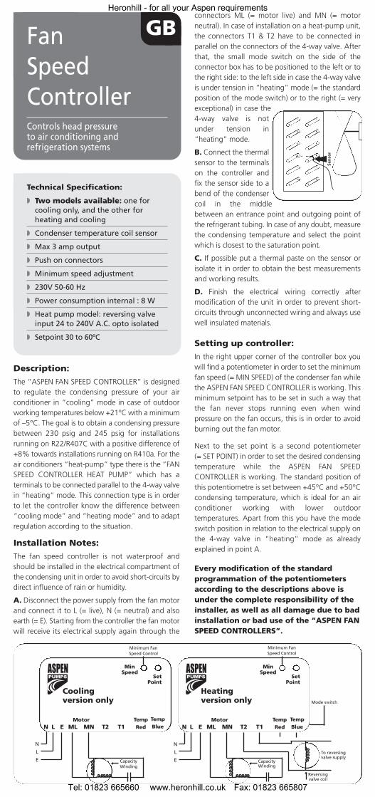
connectors ML (= motor live) and MN (= motorneutral). In case of installation on a heat-pump unit,the connectors T1 & T2 have to be connected inparallel on the connectors of the 4-way valve. Afterthat, the small mode switch on the side of theconnector box has to be positioned to the left or tothe right side: to the left side in case the 4-way valveis under tension in “heating” mode (= the standardposition of the mode switch) or to the right (= veryexceptional) in case the4-way valve is notunder tension in“heating” mode.
B. Connect the thermalsensor to the terminalson the controller andfix the sensor side to abend of the condensercoil in the middlebetween an entrance point and outgoing point ofthe refrigerant tubing. In case of any doubt, measurethe condensing temperature and select the pointwhich is closest to the saturation point.
C. If possible put a thermal paste on the sensor orisolate it in order to obtain the best measurementsand working results.
D. Finish the electrical wiring correctly aftermodification of the unit in order to prevent short-circuits through unconnected wiring and always usewell insulated materials.
Setting up controller:
In the right upper corner of the controller box youwill find a potentiometer in order to set the minimumfan speed (= MIN SPEED) of the condenser fan whilethe ASPEN FAN SPEED CONTROLLER is working. Thisminimum setpoint has to be set in such a way thatthe fan never stops running even when windpressure on the fan occurs, this is in order to avoidburning out the fan motor.
Next to the set point is a second potentiometer (= SET POINT) in order to set the desired condensingtemperature while the ASPEN FAN SPEEDCONTROLLER is working. The standard position ofthis potentiometre is set between +45°C and +50°Ccondensing temperature, which is ideal for an airconditioner working with lower outdoortemperatures. Apart from this you have the modeswitch position in relation to the electrical supply onthe 4-way valve in “heating” mode as alreadyexplained in point A.
Every modification of the standardprogrammation of the potentiometersaccording to the descriptions above isunder the complete responsibility of theinstaller, as well as all damage due to badinstallation or bad use of the “ASPEN FANSPEED CONTROLLERS”.
Technical Specification:
� Two models available: one for cooling only, and the other for heating and cooling
� Condenser temperature coil sensor
� Max 3 amp output
� Push on connectors
� Minimum speed adjustment
� 230V 50-60 Hz
� Power consumption internal : 8 W
� Heat pump model: reversing valve input 24 to 240V A.C. opto isolated
� Setpoint 30 to 60ºC
GBFanSpeedControllerControls head pressureto air conditioning and refrigeration systems
N L E ML MN T2 T1Motor Temp
Red
MinSpeed
SetPoint
Minimum FanSpeed Control
N
L
E
N L E ML MN T2 T1Motor Temp
Red
MinSpeed
SetPoint
Minimum FanSpeed Control
N
L
E
Mode switch
To reversingvalve supply
CapacityWinding
Cooling version only
Heating version only
TempBlue
TempBlue
CapacityWinding
Reversingvalve coil
Heronhill - for all your Aspen requirements
Tel: 01823 665660 www.heronhill.co.uk Fax: 01823 665807

N L E ML MN T2 T1Moteur Temp
Rouge
MinSpeed
SetPoint
VitesseMinimum
N
L
E
N L E ML MN T2 T1Moteur Temp
Red
MinSpeed
SetPoint
Vitesse Minimumde ventilation
N
L
E
Mode switch
alimentation dela vanne 4 voies
modele froid seul modelereversible
TempBleu
TempBlue
capacitéd’ecoulement
vanne 4voie
Description:
Le “ASPEN FAN SPEED CONTROLLER” est conçu pourune régulation de pression de condensation de votreclimatiseur en fonctionnement “froid” en cas defonctionnement à températures extérieures de moins de+21°C avec un minimum de -5°C. Le but est d’atteindreune pression de condensation entre 230 psig et 245 psigpar rapport aux installations R22/R407C avec unedifférence positive de +8% pour les installations R410a.Pour les climatiseurs réversible, il existe une version “FANSPEED CONTROLLER HEAT PUMP” qui est prévu d’unraccordement parallèle à brancher sur la vanne 4-voiesen fonctionnement chauffage, afin de permettre leboîtier de connaître la différence entre fonctionnement“froid seul” et fonctionnement “chauffage” et de cerégler selon la situation.
Instructions d’installation:
Le boîtier qui est non résistant aux influences directesd’intempéries, doit être positionné dans le compartimentélectrique du groupe de condensation afin d’éviter court-circuits par influence direct de pluie ou humidité.
A. Déconnectez l’alimentation du moteur de ventilationet branchez celui-ci au L (= phase) et N (= neutre) duboîtier, ainsi que la terre. A partir du boîtier, le moteurde ventilation doît de nouveau recevoir son alimentation
électrique par les bornes ML (= phase) et MN (= neutre).
– En cas d’installation sur un appareil pompe-à-chaleur,il faut raccorder les bornes T1 & T2 en parallèle sur lesbornes de la vanne 4-voies. Ensuite il faut positionnerle petit interrupteur (= mode switch) sur la façade duboîtier à gauche ou à droite : à gauche en case que lavanne 4-voies est sous tension en fonctionnement“chaud” (= position standard du boîtier) ou à droite (= très exceptionellement) en case que la vannes 4-voiesn’est pas sous tension en fonctionnement “chaud”.
B. Raccordez le senseurthermique aux bornesdu boîtier et fixez-le auniveau d’un coude enhaut de la batterie decondensation. En casde doûte, mesurer la température decondensation afin desélecter le point qui se trouve le plus proche du pointde saturation.
C. Si possible, prévoyez le senseur d’une pâtethermique ou isolation autocollante afin d’obtenir desmesures optimales.
D. Finissez le cablage électrique d’une manièrecorrecte après la modification de l’appareil, afind’éviter court-circuits par des fils non-attachées etutilisez toujours des matériaux bien isolés.
Possibilitées de mise au point:
– Dans le coin supérieur, côté droit, du boîtier se trouveun potentiomèter pour le règlage de la vitesse deventilation minimale (= MIN SPEED) du ventilateurcondenseur lors du fonctionnement du “ASPEN FANSPEED CONTROLLER”. Celui-ci doît être mise au pointde façon que le moteur de ventilation ne puisse jamaiscesser de tourner en vitesse de ventilation minimale,par exemple en cas de vent soufflant sur l’hélice afind’éviter brûlure du moteur de ventilation.– A côté de ce point se trouve un deuxièmepotentionmèter (= SET POINT) pour mise au point dela température de condensation désirée lors dufonctionnement du kit ASPEN. La position standard dece potentionmètre est d’environ +45°C à +50°Ctempérature de condensation, ce qui est optimal pourfonctionnement du climatiseur avec températuresextérieures plus basses.
Encore vous avez la position du mode switch enfonction de l’alimentation sur la vanne 4-voies enfonctionnement “chaud” de l’appareil, qui est déjàexpliqué en point A.
Chaque modification de la programmationstandard des potentiomèters selondescription ci-dessus se fait sur laresponsabilité entière de l’installateur, ainsique toute endommagement suite à lamauvaise utilisation ou mauvaiseinstallation des “ASPEN FAN SPEEDCONTROLLERS”.
Deux modèles disponibles :
� Un pour les appareils froids seuls et unautre pour les appareils réversibles
� Fonctionne par détection de température
� Max 3 ampère
� Connections par broches
� Réglage de vitesse minimum
� 230V 50-60 Hz
� Consommation : 8W
� Modèle réversible : Branchement sur la vanne 4 voies (alimentation entre 24 et 230V)
� Température de consigne de 30 à 60°C
F
Kit toutessaisonsrégulation par prise de temperaturesur le condenseur
capacitéd’ecoulement
Heronhill - for all your Aspen requirements
Tel: 01823 665660 www.heronhill.co.uk Fax: 01823 665807

N L E ML MN T2 T1Motor Temp
Red
Mindestdrehzahl
Einstellpunkt
Einstellung derVentilator-
Mindestdrehzahl
N
L
E
N L E ML MN T2 T1Motor Temp
Rot
Einstellung derVentilator-
Mindestdrehzahl
N
L
E
Modusumschalter
ZuUmschaltventilanschlussKapazitat
swindung
Version„Nur Kühlen”
Nur Version„Heizen”
TempBlue
TempBlau
Kapazitatswindung
Umschaltventilspule
Beschreibung:
Der ASPEN VENTILATOR-DREHZAHLREGLER wurdeentwickelt, um den Kondensationsdruck IhrerKlimaanlage im Modus „Kühlen“ zu regeln, falls dieAußentemperatur im Betrieb unter +21 °C liegt undmindestens –5 °C beträgt. Das Ziel ist, einenKondensationsdruck zwischen 230 psig und 245 psigbei Anlagen zu erreichen, die mit R22/R407C undeiner positiven Differenz von +8 % in Bezug aufAnlagen mit R410a arbeiten. Für Klimaanlagen vomTyp „Wärmepumpe“ gibt es den VENTILATOR-DREHZAHLREGLER WÄRMEPUMPE, der paralleleAnschlüsse für das 4-Wege-Ventil im Modus„Heizen“ besitzt. Dieser Anschlusstyp ist erforderlich,um den Regler den Unterschied zwischen „Kühlen“und „Heizen“ wissen zu lassen und die Regelung andie Situation anzupassen.
Installationshinweise:
Der Ventilator-Drehzahlregler ist nicht wasserdichtund sollte im Schaltschrank des Kondensatorsinstalliert werden, um Kurzschlüsse durch direkteEinwirkung von Regen oder Feuchtigkeit zuvermeiden.
A. Trennen Sie die Stromversorgung vomVentilatormotor und verbinden Sie sie mit L (= Phase),N (= Nullleiter) und erden Sie ihn auch (= E). DerVentilatormotor erhält seine Stromzufuhr dann vomRegler über die Anschlüsse ML (= Phase) und MN
(= Nullleiter). Bei Installation an einerWärmepumpeneinheit müssen die Anschlüsse T1und T2 parallel an die Anschlüsse des 4-Wege-Ventilsangeschlossen werden. Dann muss der kleine DIP-Schalter an der Vorderseite der Anschlussbox auf dielinke oder die rechte Seite gestellt werden: auf dielinke Seite, falls das 4-Wege-Ventil im Modus„Heizen“ stromführend ist (= die Standardpositiondes DIP-Schalters) oder nach rechts (= sehraußergewöhnliche Situation), falls das 4-Wege-Ventilim Modus „Heizen“nicht stromführend ist.
B. Schließen Sie denWärmesensor an dieAnschlüsse des Reglersan und befestigen Sieden Sensor neben einer Biegung derKondensatorschlange,in der Mitte zwischeneinem Eingangs- undAusgangspunkt der Kühlmittelleitung.Im Zweifelsfall messen Sie dieKondensatortemperatur und wählen den Punkt, dersich am dichtesten am Sättigungspunkt befindet.
C. Wenn möglich, montieren Sie den Sensor mitWärmeleitpaste oder isolieren ihn, um bestmöglicheMesswerte und Betriebsleistung zu erhalten.
D. Beenden Sie die elektrische Verkabelung nachÄnderung der Einheit ordnungsgemäß, umKurzschlüsse durch nicht angeschlossene Kabel zuverhindern, und benutzen Sie immer isolierteMaterialien.
Einstellung des Reglers:
In der rechten oberen Ecke des Reglergehäusesbefindet sich ein Potentiometer zur Einstellung der Mindestdrehzahl (= MIN SPEED) desKondensatorventilators während des Betriebs desASPEN VENTILATOR-DREHZAHLREGLERS. DieseMinimaldrehzahl muss so eingestellt werden, dass derVentilator niemals aufhört zu laufen, selbst wenn einGegendruck aufgrund von Winddruck auf dieLüfterspule auftritt. Dies verhindert, dass derVentilatormotor durchbrennt.
Neben dem Einstellpunkt befindet sich ein zweitesPotentiometer (= SET POINT), mit dem diegewünschte Kondensationstemperatur während desBetriebs des ASPEN VENTILATOR-DREHZAHLREGLERSeingestellt wird. Die Standardposition diesesPotentiometers ist auf einen Wert zwischen +45 °Cund +50 °C Kondensationstemperatur eingestellt,dies ist ideal für eine Klimaanlage, die bei niedrigenAußentemperaturen arbeitet. Abgesehen davonkönnen Sie die Stellung des DIP-Schalters für dieStromversorgung des 4-Wege-Ventils im Modus„Heizen“ einstellen, wie schon unter Punkt Abeschrieben.
Jede Änderung derStandardprogrammierung derPotentiometer gemäß der obenstehendenBeschreibung erfolgt unter alleinigerVerantwortung des Installateurs; die giltebenso für Schäden aufgrund fehlerhafterInstallation und falschen Einsatzes desASPEN VENTILATOR-DREHZAHLREGLERS.
Technische Daten:
� Zwei Modelle verfügbar: Eins für Kühlen allein, das andere für Heizen und Kühlen
� Sensor für Kondensatorschlangentemperatur
� Max. 3 A Ausgangsstrom
� Steckanschlüsse
� Einstellung der Mindestdrehzahl
� 230 V 50-60 Hz
� Interne Leistungsaufnahme: 8 W
� Wärmepumpenmodell: Umschaltventil-Eingang 24 bis 240 VAC mit Optokoppler Einstellpunkt 30 bis 60 °C
DVentilator-Drehzahl-reglerRegelt den Kopfdruck vonKlimaanlagen- undKühlsystemen
Mindestdrehzahl
Einstellpunkt
Heronhill - for all your Aspen requirements
Tel: 01823 665660 www.heronhill.co.uk Fax: 01823 665807
Descripción:
El Variador de velocidad fuediseñado para controlarlas presiones de trabajo del sistema contemperaturas exteriores de 21ºC o inferiores,utilizando la unidad en modo frio.
Para el correcto funcionamiento en equipos de aireacondicionado debera mantener la presion de altaentre 230 a 245Psig, utilzando refrigerante R-22En los modelos frio calor por bomba (heat pump),tiene la posibilidad de energizar o no la valvulainversora (24 o 22VAC).
Instrucciones de instalacion:
El variador debe colocarse dentro de la unidadcondensadora (no es a prueba de agua), en unaposicion donde sea facil regularlo o ajustario.
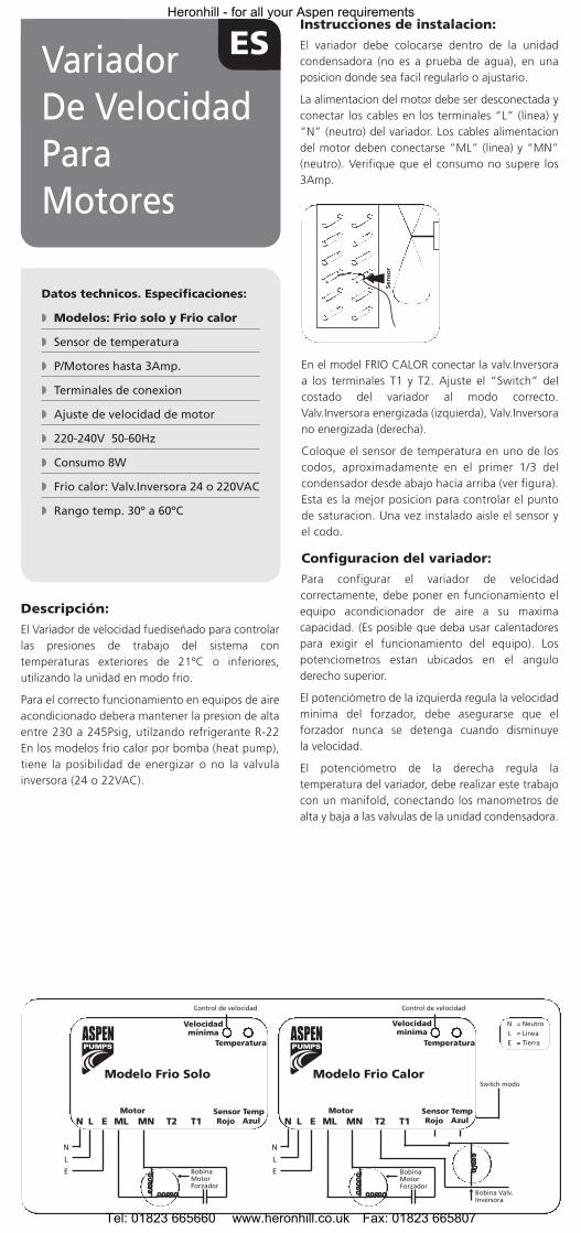
La alimentacion del motor debe ser desconectada yconectar los cables en los terminales “L” (linea) y“N” (neutro) del variador. Los cables alimentaciondel motor deben conectarse “ML” (linea) y “MN”(neutro). Verifique que el consumo no supere los3Amp.
En el model FRIO CALOR conectar la valv.Inversoraa los terminales T1 y T2. Ajuste el “Switch” delcostado del variador al modo correcto.Valv.Inversora energizada (izquierda), Valv.Inversorano energizada (derecha).
Coloque el sensor de temperatura en uno de loscodos, aproximadamente en el primer 1/3 delcondensador desde abajo hacia arriba (ver figura).Esta es la mejor posicion para controlar el puntode saturacion. Una vez instalado aisle el sensor yel codo.
Configuracion del variador:
Para configurar el variador de velocidadcorrectamente, debe poner en funcionamiento elequipo acondicionador de aire a su maximacapacidad. (Es posible que deba usar calentadorespara exigir el funcionamiento del equipo). Lospotenciometros estan ubicados en el anguloderecho superior.
El potenciómetro de la izquierda regula la velocidadminima del forzador, debe asegurarse que elforzador nunca se detenga cuando disminuye la velocidad.
El potenciómetro de la derecha regula latemperatura del variador, debe realizar este trabajocon un manifold, conectando los manometros dealta y baja a las valvulas de la unidad condensadora.
ESVariadorDe VelocidadParaMotores
Datos technicos. Especificaciones:
� Modelos: Frio solo y Frio calor
� Sensor de temperatura
� P/Motores hasta 3Amp.
� Terminales de conexion
� Ajuste de velocidad de motor
� 220-240V 50-60Hz
� Consumo 8W
� Frio calor: Valv.Inversora 24 o 220VAC
� Rango temp. 30º a 60ºC
N L E ML MN T2 T1Motor
Rojo
Velocidad minima
Control de velocidad
N
L
E
N L E ML MN T2 T1Motor
Control de velocidad
N
L
E
Switch modo
BobinaMotorForzador
Modelo Frio Solo Modelo Frio Calor
Azul
Bobina Valv.Inversora
BobinaMotorForzador
NLE
= Neutro= Linea= Tierra
Sensor Temp
Velocidad minima
Temperatura Temperatura
Rojo AzulSensor Temp
Heronhill - for all your Aspen requirements
Tel: 01823 665660 www.heronhill.co.uk Fax: 01823 665807
Part
No.
124
5 A
SPEN
-9/0
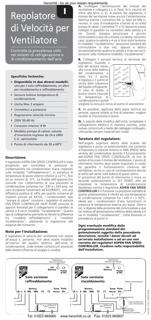
8N L E ML MN T2 T1Motore Temp
Rosso
VelMinima Punto
di Rif.
RegolazioneMinimo Ventilatore
N
L
E
N L E ML MN T2 T1Motore Temp
Rosso
VelMinima Punto
di Rif.
RegolazioneMinimo Ventilatore
N
L
E
Modo commutazione
Verso aliment.nevalv. d’inversione
Bobina diCapacità
Solo versioneraffreddamento
Solo versioneriscaldamento
TempBlu
TempBlu
Bobina diCapacità
Bobina dellavalvola d’inversione
DescrizioneIl regolatore ASPEN FAN SPEED CONTROLLER è statoprogettato per controllare la pressione dicondensazione nei condizionatori d’aria impostatisulla modalità “raffreddamento”, in presenza ditemperature di lavoro esterne inferiori a +21°C, finoad un minimo di -5°C. La finalità dell’apparecchiocoincide con l’ottenimento di una pressione dicondensazione compresa tra i 230 e i 245 psig, nelcaso d’impianti funzionanti ad R22/R407C, con unadifferenza positiva di +8% per quanto concerne gliimpianti caricati ad R410a. I condizionatori tipo“pompa di calore” montano i regolatori di velocitàFAN SPEED CONTROLLER HEAT PUMP, provvisti diappositi terminali per il collegamento in parallelo divalvole a 4 vie in modalità “riscaldamento”. Questotipo di collegamento permette di rilevare la differenzatra “modalità raffreddamento” e “modalitàriscaldamento”, adattando la regolazione alleesigenze del momento.
Note per l’Installazione:Il regolatore di velocità per ventilatore non resisteall’acqua e, pertanto, non deve essere installatoall’interno del quadro elettrico dell’unità dicondensazione, onde evitare cortocircuiti provocatidalla diretta influenza di pioggia e umidità.
A. Scollegare l’alimentazione dal motore delventilatore e collegarla a L (= fase), N (= neutro) edinfine alla terra (= E). A partire dal regolatore, ilmotore del ventilatore riceve ancora l’alimentazioneelettrica tramite i connettori ML (= fase) ed MN (=neutro). In caso d’installazione a bordo di un’unitàpompa di calore, i connettori T1 e T2 dovranno esserecollegati in parallelo sui connettori della valvola a 4vie. Quindi, bisogna posizionare il piccolocommutatore a due vie a sinistra o a destra: nel primocaso, qualora la valvola a 4 vie si trovi sotto tensionein modalità “riscaldamento” (posizione standard delcommutatore a due vie), oppure a destra(eccezionalmente) qualora la valvola a 4 vie non sia intensione nella medesima modalità “riscaldamento”.
B. Collegare il sensore termico ai terminali delregolatore, fissando illato del sensore stessoalla curva della bobinadel condensatore, ametà tra il puntod’ingresso e il punto diuscita della tubazionedel liquido refrigerante.In caso di dubbi, èbuona norma misurarela temperatura dicondensazione e quindiscegliere la zona più vicino al punto di saturazione.
C. Se possibile, applicare della pasta termica sulsensore, oppure isolarlo al fine di ottenere i miglioririsultati di misurazione e lavoro.
D. A seguito della modifica dell’unità, completare ilcollegamento elettrico in maniera corretta, ondeevitare cortocircuiti a livello del cablaggio scollegato,utilizzando sempre materiali ben isolati.
Taratura del regolatore:Nell’angolo superiore destro della scatola delregolatore è posto un potenziometro che consented’impostare la velocità minima (= MIN SPEED) dellaventola del condensatore durante il funzionamentodell’ASPEN FAN SPEED CONTROLLER. Al fine dievitare di bruciare il motore del ventilatore, il punto diriferimento minimo deve essere impostato in mododa garantire il funzionamento continuo delventilatore, anche in caso di contropressione dovutaal soffio del vento sulla bobina di quest’ultimo.In prossimità del punto di riferimento si trova unsecondo potenziometro (= SET POINT) atto adimpostare la temperatura di condensazionedesiderata mentre il regolatore ASPEN FAN SPEEDCONTROLLER è in funzione. La posizione standard diquesto potenziometro è riferita ad una temperaturadi condensazione compresa tra i +45 e i + 50°C,ideale per i condizionatori d’aria funzionanti inpresenza di temperature esterne più basse. Oltre aciò, si dispone della posizione del commutatore a duevie relativa all’alimentazione elettrica della valvola a 4vie in modalità “riscaldamento”, come illustrato inprecedenza al punto A.
Ogni eventuale modifica dellaprogrammazione standard deipotenziometri oggetto della precedentedescrizione, nonché i danni dovuti adun’errata installazione o ad un uso noncorretto dei regolatori ASPEN FAN SPEEDCONTROLLER, ricadono sulla responsabilitàdell’installatore.
IRegolatoredi Velocità perVentilatoreControlla la prevalenza utile nei sistemi di refrigerazione edi condizionamento dell’aria
Specifiche Techniche:
� Disponibile in due diversi modelli:uno per il solo raffreddamento, un altro per riscaldamento e raffreddamento
� Sensore bobina temperatura di condensazione
� Uscita Max 3 ampere
� Connettori a pressione
� Regolazione velocità minima
� 230V 50-60 Hz
� Consumo interno: 8 W
� Modello pompa di calore: valvola d’inversione ingresso da 24 a 240V C.A. optoisolato
� Punto di riferimento da 30 a 60ºC
Heronhill - for all your Aspen requirements
Tel: 01823 665660 www.heronhill.co.uk Fax: 01823 665807