designation:e2112–01 designation: e 2112 – 07
TRANSCRIPT

Designation:E2112–01 Designation: E 2112 – 07
Standard Practice forInstallation of Exterior Windows, Doors and Skylights1
This standard is issued under the fixed designation E 2112; the number immediately following the designation indicates the year oforiginal adoption or, in the case of revision, the year of last revision. A number in parentheses indicates the year of last reapproval. Asuperscript epsilon (e) indicates an editorial change since the last revision or reapproval.
INTRODUCTION
This document is intended to provide technical guidance to organizations that are developingtraining programs for installers of fenestration units in low-rise residential and light commercialstructures. The majority of fenestration units selected for installation in these types of structures arecertified as meeting specified performance characteristics in standardized laboratory testing. Experi-ence indicates, however, that the performance of fenestration installations is frequently significantlyinferior to the performance of the manufactured units in laboratory testing. Installation of fenestrationunits can significantly influence in-service performance.
The requirements promulgated in this practice have, by consensus, (of individuals with specializedknowledge concerning installation of fenestration units) been identified as necessary to ensure thatas-installed performance is roughly equivalent to performance in laboratory testing. The task groupresponsible for development of this practice recognizes that building owners sometimes, accept asadequate, in-service performance of fenestration installations that are significantly inferior those of theunits in laboratory testing. This practice is not intended for use in such circumstances, where ownerexpectations are modest. The intent of this practice is to provide guidance to those concerned withensuring that as-installed performance is comparable to the capabilities of the units installed for a solidmajority of installations.
A particularly noticeable behavior that indicates deficiencies in installation is rainwater leakage.Rainwater leakage has been the leading reason for dissatisfaction of building owners with performanceof fenestration installations. For this reason, this practice places greater emphasis on preventing orlimiting rainwater leakage than on any other single performance characteristic.
This practice emphasizes that the water-shedding surfaces of fenestration units must be adequatelyintegrated with adjacent water-shedding surfaces of the building envelope. It does not, however,attempt to promulgate requirements for water-shedding surfaces of building envelopes other thanthose interfacing with fenestration units. The standard assumes that the basic design of the building’swater-shedding system is adequate, that is, that either (1) there is a high probability that the outermostbuilding surface will dependably prevent all water entry, or (2) the building envelope incorporates aneffective concealed barrier that will dependably prevent further intrusion of incidental water thatbreaches the outermost surface. The practice further assumes that fenestration units can be dependablysealed to, and integrated with, at least one of these surfaces. If the basic design of the building’swater-shedding system is inadequate, or does not allow for reliable integration of fenestration unitsinto it, competent installation of the units is unlikely to nullify these deficiencies.
1. Scope
1.1 This practice covers the installation of fenestration products in new and existing construction. For the purpose of thispractice, fenestration products shall be limited to windows, sliding patio-type doors, swinging patio type doors, and skylights, asused primarily in residential and light commercial buildings.
1.2 This practice assumes that the installer possesses basic woodworking skills and an understanding of wall and roofconstruction, sheet metal work, and joint sealant practices.
1 This practice is under the jurisdiction of ASTM Committee E06 on Building Constructions and is the direct responsibility of Subcommittee E06.51 on Performance ofWindows, Doors, Skylights and Curtain Walls.
Current edition approved July 10, 2001. Published September 2002.1 This practice is under the jurisdiction of ASTM Committee E06 on Performance of Buildings and is the direct responsibility of Subcommittee E06.51 on Performance
of Windows, Doors, Skylights and Curtain Walls.Current edition approved Feb. 1, 2007. Published March 2007. Originally approved in 2001. Last previous edition approved in 2001 as E 2112 – 01.
1
This document is not an ASTM standard and is intended only to provide the user of an ASTM standard an indication of what changes have been made to the previous version. Becauseit may not be technically possible to adequately depict all changes accurately, ASTM recommends that users consult prior editions as appropriate. In all cases only the current versionof the standard as published by ASTM is to be considered the official document.
Copyright © ASTM International, 100 Barr Harbor Drive, PO Box C700, West Conshohocken, PA 19428-2959, United States.
Copyright by ASTM Int'l (all rights reserved); Tue Jan 29 17:21:34 EST 2008Downloaded/printed byHarry N Nelson () pursuant to License Agreement. No further reproductions authorized.

1.3 This practice attempts to instruct and familiarize the installer with the concepts of both Barrier Systems andMembrane/Drainage Systems, in order to ensure the continuity of the building envelope. This practice attempts to educate theinstaller, builder, architect, and other users in the identification and understanding of the water shedding system of the buildingenvelope.
1.4 This practice covers the installation process from pre-installation procedures through post-installation procedures, for singleunits or factory-mulled multiple units in a single opening. It does not cover the fabrication or assembly of multiple units, whethersuch fabrication takes place in a factory or at the intended installation site. The installer should check with the manufacturer offactory-assembled units for instructions for anchoring. When using field-mulled units, follow manufacturer’s recommendationsand make certain that they meet applicable codes. This practice does not cover the selection of appropriate fenestration productsfor a given application, nor the selection of other products or systems for use in the installation.
1.5 This practice provides minimum requirements that will help to accomplish the installation of fenestration products in aneffective manner. Actual conditions in buildings vary greatly and, in some cases, substantial additional precautions may berequired. In the event that the manufacturer’s installation instructions provided with the product conflict with requirements of thispractice, the manufacturer’s instructions shall prevail. This practice is not intended to limit or exclude other new procedures thatmay refine or further improve the effectiveness of fenestration installation.
1.5.1 This practice is intended to be used for background information in order to develop training manuals and trainingprograms. Further, this practice attempts to consolidate and unify the various steps of construction, tying together the various tradesinvolved with the continuity between fenestration products and the building envelope.
1.6 The text of this practice references notes and footnotes that provide explanatory material. These notes and footnotes(excluding those in tables and figures) shall not be considered as requirements of this practice.
1.7 The values stated in inch-pound units are to be regarded as the standard. The values shown in parentheses are for informationonly.
1.8 This standard has not been created to address all issues related to every possible installation situation one might experiencein the field. Furthermore, this practice does not purport to provide fail-safe installation methods, assurance or protection againstinstallation deficiencies, or a standard by which architects can specify or ensure delivered performance.
NOTE 1—There are no ISO standards covering the primary subject matter of this practice.
1.9 This practice does not purport to address all of the safety concerns, if any, associated with its use. It is the responsibilityof the user of this standard to establish appropriate safety and health practices and to determine the applicability of regulatorylimitations prior to use. For specific precautionary statements, see Section 5, Related Procedures. Where a lead hazard is knownor suspected, refer to ASTM Standards on Lead Hazards Associated with Buildings and to applicable state and federal regulations.Where an asbestos hazard is known or suspected, refer to the ASTM Manual on Asbestos Control , and to applicable state andfederal regulations.
1.10 Table of Contents:Section
Scope 1Table of Contents 1.10
Referenced Documents 2Terminology 3
Definitions 3.1Description of Terms Specific to this Standard 3.2Abbreviations 3.3
Significance and Use 4Related Issues and Procedures 5
Continuity with the Weather Barrier Systems 5.1Joints and Anchorages 5.2Moisture Entrapment 5.3Weather Resistant Barrier 5.4Weatherability 5.5Construction Sequence 5.6Construction Damage 5.7Inspection 5.8Rough Opening 5.9
Rough Opening Size 5.9.1Insulating or Filling the Rough Opening Gap 5.9.2
Materials Protection 5.10Cleaning and Maintenance 5.11Dissimilar Materials 5.12Flashing Requirements 5.13Fastening Systems/Anchorage 5.14Shimming 5.15Panning Systems and Subsills for Weatherability 5.16Pre-Installation Procedures 5.17Sealants—Selection and Use 5.18
E 2112 – 07
2Copyright by ASTM Int'l (all rights reserved); Tue Jan 29 17:21:34 EST 2008Downloaded/printed byHarry N Nelson () pursuant to License Agreement. No further reproductions authorized.

Window Cleaner Anchors and Related SafetyHardware
5.19
Continuity Between the Fenestration Products andOther Components of the Building Envelope
6
Water Shedding Strategies of Wall and Roof Systems 7Concept of Surface Barrier Systems and
Membrane/Drainage Systems7.1
Surface Barrier Systems 7.1.1Membrane/Drainage Systems 7.1.2
Identification of Systems 7.2Installation Methods For Windows 8
Windows in Walls Utilizing a Membrane/DrainageSystem
8.1
Windows with Perimeter Mounting Flanges(Nail Fins) in Drainage TypeWall Construction
8.1.1
Flange Types 8.1.1.1Selection of Installation Method 8.1.1.2
Method A 8.1.1.3.1Method B 8.1.1.3.2Method A1 8.1.1.3.3Method B1 8.1.1.3.4
Non-Finned Windows in Membrane/DrainageType Walls
8.1.2
Windows in Walls Utilizing a Barrier Wall System(Sealant Method)
8.2
Windows in Walls Utilizing an Exterior Barrier System(EIFS or Direct Applied)
8.3
Special Considerations 8.4Aluminum Framed Windows 8.4.1Vinyl Framed Windows 8.4.2
Replacement Window Installation 8.5Partial Window Replacement for Existing Integral
Flange Windows8.5.1
Partial Replacement of Mill Shop Wood Windows 8.5.2Complete Window Replacement 8.5.3
Destructive Window Replacement (Fin Type) 8.5.3.1Non-Destructive Window Replacement
(Non-Fin Type)8.5.3.2
Installation Methods for Doors 9Doors in Walls Utilizing a Membrane/Drainage System 9.1
Doors with Perimeter Mounting Flanges(Nailing Fins) in Drainage TypeWall Construction
9.1.1
Flange Types 9.1.1.1Selection of Installation Method 9.1.1.2
Method A 9.1.1.4.1Method B 9.1.1.4.2Method A1 9.1.1.4.3Method B1 9.1.1.4.4
Hinged Swing (Non-finned) Doors in Membrane/Drainage Type Walls
9.1.2
Installation Methods for Skylights 10Product Types 10.1Flashing Procedures 10.2Aluminum/Copper Sheet Flashing 10.3Aluminum/Copper Step Flashing (Fabricated or
Engineered)10.4
Membrane Flashing 10.5Post-Installation Procedures 11Keywords 12Air Barrier Foam Sealant Used in the Rough
Opening GapAnnex A1
Emergency Escape and Rescue Requirements Annex A2Minimum Height Requirements for Interior Height of
Pan FlashingAnnex A3
Sealants Annex A4Window/Door Flashing Types Appendix X1Cautions for Installation Appendix X2Bibliography/Other Referenced Installation Guides Appendix X3
2. Referenced Documents
2.1 ASTM Standards: 2
2 For referenced ASTM standards, visit the ASTM website, www.astm.org, or contact ASTM Customer Service at [email protected]. For Annual Book of ASTM Standards, Vol 01.06.volume information, refer to the standard’s Document Summary page on the ASTM website.
E 2112 – 07
3Copyright by ASTM Int'l (all rights reserved); Tue Jan 29 17:21:34 EST 2008Downloaded/printed byHarry N Nelson () pursuant to License Agreement. No further reproductions authorized.

A 123 Specification for Zinc (Hot Dipped Galvanized) Coatings on Iron and Steel ProductsB 456 Specification for Electrodeposited Coatings of Copper plus Nickel Plus Chromium and Nickel Plus ChromiumB 663 Specification for Silver-Tungsten Carbide Electrical Contact MaterialB 766 Specification for Electrodeposited Coatings of CadmiumC 717 Terminology of Building Seals and SealantsC 755 Practice for Selection of Vapor Barriers for Thermal InsulationC 794Test Method for Adhesion-in-Peel of Elastomeric Joint Sealants5
C797Practices and Terminology for Use of Oil- and Resin-Based Putty and Glazing Compounds5 Test Method forAdhesion-in-Peel of Elastomeric Joint Sealants
C 834 Specification for Latex SealantsC 920 Specification for Elastomeric Joint SealantsC 1085 Specification for Butyl Rubber-Based Solvent-Release Sealants3
C 1193 Guide for Use of Joint SealantsC 1281 Specification for Preformed Tape Sealants for Glazing ApplicationsC 1299 Guide for Use in Selection of Liquid-Applied SealantsC 1311 Specification for Solvent Release SealantsC 1382 Test Method for Determining Tensile Adhesion Properties of Sealants When Used in Exterior Insulation and Finish
Systems (EIFS) JointsC 1397 Practice for Application of Class PB Exterior Insulation and Finish SystemsD 779 Test Method for Water Resistance of Paper, Paperboard, and Other Sheet Materials by the Dry Indicator MethodD 1970 Specification for Self-Adhering Polymer Modified Bituminous Sheet Materials, Used as Steep Roofing Underlayment
for Ice Dam ProtectionD 2822 Specification for Asphalt Roof CementE 283 Test Method for Determining Rate of Air Leakage Through Exterior Windows, Curtain Walls, and Doors Under Specified
Pressure Differences Across the SpecimenE 331 Test Method for Water Penetration of Exterior Windows, Skylights, Doors, and Curtain Walls by Uniform Static Air
Pressure DifferenceE 547 Test Method for Water Penetration of Exterior Windows, Skylights, Doors, and Curtain Walls by Cyclic Static Air
Pressure DifferenceE 631 Terminology of Building ConstructionsE 783 Test Method for Field Measurement of Air Leakage Through Installed Exterior Windows and DoorsE 1105 Test Method for Field Determination of Water Penetration of Installed Exterior Windows, Skylights, Doors and Curtain
Walls by Uniform or Cyclic Static Air Pressure Difference2.2 AAMA Standards:4
502 Voluntary Specification for Field Testing of Windows and Doors800 Voluntary Specifications and Test Methods for Sealants808.3 Voluntary Specifications for Exterior Perimeter Sealing Compounds809.2 Voluntary Specification for Non Drying Sealant850 Fenestration Sealants Guide Manual2.3 ANSI/AAMA/NWWDA Standard: ANSI/AAMA/WDMA Standard:4
101/I.S.2 Voluntary Specifications for Aluminum, Vinyl (PVC) and Wood Windows and Glass Doors2.4 AAMA/WDMA Standard:4
1600/IS7 Voluntary Specifications for Roof Windows and Skylights2.5 ANSI/ASME Standard:5
A39.1 Standard, Safety Requirements for Window Cleaning2.6 ANSI/EIMA Standard:5
99-A-200 Exterior Insulation and Finish Systems (EIFS)2.7 ANSI/ISDI Standard:5
102 Insulated Steel Door Systems—Installation Standard2.8 CSA Standards:6
3 Annual Book of ASTM Standards, Vol 02.05.3 Discontinued; see Annual Book of ASTM Standards, Vol. 04.07. Replaced by Specification C 1311.4 Annual Book of ASTM Standards, Vol 02.04.4 Available from American Architectural Manufacturers Assoc., 1827 Walden Office Sq., Suite 550, Schaumburg, IL 60173–4268.5 Annual Book of ASTM Standards, Vol 04.07.5 Available from American National Standards Institute (ANSI), 25 W. 43rd St., 4th Floor, New York, NY 10036.6 Annual Book of ASTM Standards, Vol 04.06.6 Available from Canadian Standards Association, 178 Rexdale Blvd., Toronto, Ontario M9W 1R3, Canada.
E 2112 – 07
4Copyright by ASTM Int'l (all rights reserved); Tue Jan 29 17:21:34 EST 2008Downloaded/printed byHarry N Nelson () pursuant to License Agreement. No further reproductions authorized.

A440.4 Fenestration Product InstallationA440-M90 Windows—A National Standard of Canada2.9 CPSC Standard:7
16 CFR 1201 USA Consumer Product Safety Commission, Code of Federal Regulations; Part 1201, Safety Standard forArchitectural Glazing Materials, 1977
2.10 ICBO Standards:National Evaluation Services,Acceptance Criteria for Sloped Glass and Glazing in Solariums, Patio Covers and Prefabricated
SkylightsUniform Building Code, Chapter 2816
Uniform Building Code, Section 310.4,Access and Exit Facilities and Emergency Escapes16
Uniform Building Code, Section 2325.1, Fastenings16
Uniform Building Code, Section 2406,Safety Glazing16
2.11 WDMA Standard:8
I.S.4 Industry Standard for Water-Repellent Preservative Treatment for Millwork2.122.11 OSHA Standards:9
29CFR–1926.62 29 CFR 1926.62 Lead in Construction Standard29CFR–1926.1101 Asbestos Construction Standard18 29 CFR 1926.1101 Asbestos Construction Standard
3. Terminology
3.1 Definitions—Definitions are in accordance with Terminology E 631 and Terminology C 717, unless otherwise specified.3.2 Definitions of Terms Specific to This Standard:3.2.1 accessory groove, n—a shape included on a fenestration product frame that is designed to mate with installation
accessories.3.2.2 air barrier, n—the assembly of materials used in building construction to reduce or retard the uncontrolled passage of air
into and out of the building.3.2.3 air barrier foam sealant, n—an aerosol foam product dispensed as a bead into the air gap area around the fenestration
perimeter to reduce the infiltration or exfiltration of air past the fenestration product.3.2.4 air leakage, n—also referred to as air infiltration. According to Terminology E 631 in buildings, the passage of
uncontrolled air through cracks or openings in the building envelope or its components, such as ducts, because of air pressure ortemperature difference.
3.2.5 anchor line (or anchor point), n— a line (or point) of reference on a fenestration product or the building, or both, whereattachment is made.
3.2.6 annealed glass, n—raw glass used as a glazing product.3.2.6.1 Discussion—Further processing is required to transform annealed glass into safety glazing material.3.2.7 anodic finishes, n—clear or colored coatings composed of aluminum oxide that are electrolytically deposited and are an
integral part of the aluminum substrate.3.2.7.1 Discussion—Careful control permitted by the electrolytic anodizing process provides substantial improvement over a
natural oxide film due to greater thickness, density, and hardness of these factory-produced finishes. Pre-anodic chemicaltreatments clean and prepare the aluminum for the anodic finish. The Aluminum Association classifies architectural anodic coatingsdepending on coating thickness and recommended use. Further detailed information and specifications on anodic finishes isavailable from the Aluminum Association and the American Architectural Manufacturers Association.
3.2.8 apron, n—a molding applied horizontally to the wall, directly below the window sill and used to hide the rough edge ofthe drywall or plaster below the window framing.
3.2.9 backer rod, n—a material placed into a joint, primarily to control the depth of the sealant, also serves as a bond breaker.3.2.10 barrier wall system, n—a wall system that is intended to manage all water at the exterior surface.3.2.10.1 Discussion—These wall systems consist of the exterior surface of the wall and the exterior surface of the fenestration
product, usually connected by a sealant joint.3.2.11 bead, n—sealant applied in a joint, such as sealant bead, glazing bead, and so forth. According to Terminology E 631,
in glazing, (1) a strip of metal or wood used around the periphery of a pane of glass to secure it in place (also referred to as a stop)and (2) a strip of sealant, glazing compound, or putty.
7 Discontinued; see Annual Book of ASTM Standards, Vol. 04.07. Replaced by Specification C 1311.7 Available from Superintendent of Documents, U.S. Government Printing Office, 732 North Capitol Street, NW, Mail Stop: SDE, Washington, DC 20401. Online at
www.access.gpo.gov/nara/cfr/cfr-table-search.html.8 Annual Book of ASTM Standards, Vol 04.01.8 Available from WDMA, 1400 East Touhy Avenue, Suite 470, Des Plaines, IL 60018.9 Annual Book of ASTM Standards, Vol 15.09.9 Available from U.S. Department of Labor Occupational Safety and Health Administration (OSHA), 200 Constitution Avenue, N.W., Washington D.C. 20210.
E 2112 – 07
5Copyright by ASTM Int'l (all rights reserved); Tue Jan 29 17:21:34 EST 2008Downloaded/printed byHarry N Nelson () pursuant to License Agreement. No further reproductions authorized.

3.2.12 bite, n—amount of overlap between the stop and the panel or light. According to Terminology E 631, the distance thatthe surround member (rail or stile) overlaps the glazing.
3.2.13 blind nailing, n—nailing in such a way that the nail heads are not visible on the face of the finished work.3.2.14 blind stop, n—a rectangular molding attached to the side and head of a window to serve as a stop for storm windows
and screens.3.2.15 block frame fenestration product (sometimes called box frame) , n—a type of non-finned fenestration product (either
window or door) that has no factory-applied moldings and that is installed into the rough opening either by driving fastenersthrough shimmed side jambs or by use of installation clips or brackets.
3.2.15.1 Discussion—Exterior moldings or casings may be supplied with the fenestration unit (that is, by the manufacturer) forinstallation after the unit is secured in the rough opening. It is generally easier to ensure effective integration of a block-frame unit’swater-shedding surfaces with the weather resistant barrier (WRB) of a membrane/drainage wall system than it is to accomplish thesame task with a non-finned unit to which exterior moldings have been factory-installed.
3.2.15.2 Discussion—Block-frame windows are commonly used in most of the Canadian provinces. They are relatively rare inresidential construction in the United States, where nailing flange windows and windows with factory-applied brick moldings aremore common.
3.2.16 bond breaker, n—a material used to prevent three-sided adhesion in sealant joints.3.2.17 brick mold, n—an exterior trim molding which forms a boundary between bricks or other siding and a fenestration
product.3.2.17.1 Discussion—Brick mold fenestration units are a type of non-finned product (either window or door) with
factory-supplied exterior moldings that are brick moldings. The unit may be supplied without the brick moldings attached, andintended for installation as a block-frame unit. More commonly, the brick moldings are factory-applied, and the unit is secured inthe rough opening by nailing through the brick moldings into framing members.
3.2.17.2 Discussion—Ensuring that the water shedding surfaces of the fenestration unit are effectively integrated with the WRBof a membrane/drainage wall system can be challenging. This practice does not recognize the brick moldings on fenestration unitsas being permanently effective water-shedding surfaces; finger joints in wood brick moldings may open over time unless paintmaintenance is meticulous, and upper-corner miter joints may open sufficiently to permit some water intrusion. This practiceassumes that the water-shedding surfaces of a brick mold fenestration unit are the window sash or door, the top and side jambsof the unit, and the unit’s sill. This practice further recognizes, however, that over the service life of the fenestration unit, waterleakage may occur between the side jambs and sill, which is why pan flashings are recommended for use with these units (see 8.2).
3.2.18 buck, n—a rough wooden framework, built into a window or door opening in a concrete or masonry wall, to which thewindow or door frame is secured.
3.2.19 building envelope, n—the exterior of a building.3.2.19.1 Discussion—According to Terminology E 631, the outer elements of a building, both above and below ground, that
divide the external from the internal environments.3.2.20 building paper, n—a membrane material made of cellulose paper impregnated with asphalt (to inhibit passage of liquid
water through the material) and which is commonly used as a concealed weather-resistantweather-resistive barrier inmembrane/drainage walls.
3.2.20.1 Discussion—Typically installed after windows and window flashing. Block or brick-mold windows may be installedafter building paper (defer to manufacturer’s instructions).
3.2.21 buttering, n—application of sealant compound to the flat surface of a member before placing the member in position.3.2.22 cap/capping, n—see pan/panning.3.2.23 casing, n—a trim molding used around doors and windows to cover the area between the wall and the edge of the jamb.3.2.24 caulk (non-elastomeric), n—see sealant.3.2.25 cementitious material, n—material binding aggregate particles together into a heterogeneous mass.3.2.26 channel, n—a three-sided, U-shaped opening in sash or frame to receive a light or panel.3.2.26.1 Discussion—In sash or frame units in which the light or panel is retained by a removable stop.3.2.27 channel depth, n—the measurement from the bottom of the channel to the top of the stop, or measurement from sight
line to base of channel.3.2.28 channel glazing, n—the sealing of the joints around lights or panels set in a U-shaped channel employing removable
stops.3.2.29 channel width, n—the measurement between stationary and removable stops in a U-shaped channel at its widest point.3.2.30 cladding system, n—the aesthetic covering of a building.3.2.30.1 Discussion—According to Terminology E 631, material assembly applied to a building as a non-load-bearing wall, or
attached to a wall surface as a protective and ornamental covering.3.2.31 cohibition point, n—a location where movement is restricted between the sash and the frame, such as at a hinge or lock.3.2.32 complete window replacement, n—the installation of a replacement window where the previously-installed window is
completely removed.3.2.33 composite materials, n—fenestration members which contain two or more materials, structurally combined or connected
E 2112 – 07
6Copyright by ASTM Int'l (all rights reserved); Tue Jan 29 17:21:34 EST 2008Downloaded/printed byHarry N Nelson () pursuant to License Agreement. No further reproductions authorized.

so as to perform structurally as a singular material such as poured and de-bridged aluminum shapes, fiberglass and man-made woodproducts.
3.2.34 compound, n—a formulation of ingredients, usually grouped as vehicle or polymer pigment and fillers to producecaulking compounds and elastomeric joint sealants.
3.2.35 consistency, n—degree of softness or firmness of a compound as supplied in the container.3.2.35.1 Discussion—Consistency varies according to method of application, such as gun, knife, trowel, etc. and so forth.3.2.36 construction documents, n—architectural drawings, specifications, shop drawings, manufacturing details, test reports,
contracts, building permits, applicable codes.3.2.37 counter-flashing, n—horizontally applied sheet (flashing) material that joins layers of flashings where they join the
weather resistant barrier, enhancing drainage by gravity.3.2.38 cripple stud, n—a short stud above or below a window or door opening.3.2.39 cross shims, n—see shim.3.2.40 curing, n—a chemical process which over time results in the ultimate properties of a finish or other material.3.2.41 curing agent, n—one part of a two-part sealant which, when added to the base, will cause the base to change its physical
state.3.2.42 drainage wall system, n—see membrane/drainage system.3.2.43 drip, n—any exterior horizontal course or molding that projects to the weather side of a wall or other surface to throw
off water.3.2.43.1 Discussion—A small drip groove is sometimes used on the underside of a drip cap or window sill to prevent water from
running back under the cap or window.3.2.44 drip cap, n—a molding or flashing commonly installed over windows and doors to direct water away from the building
in order to prevent seepage; also called a drip molding.3.2.44.1 Discussion—A rounded or beveled metal strip attached to the bottom of an exterior door to prevent water from draining
or blowing under the door.3.2.45 drying, n—the process of removing water from a material; usually accomplished with heated air.3.2.45.1 Discussion—According to Terminology E 631, the process of developing, solely by evaporation of volatile ingredients,
ultimate properties of a finish or other material over a specified period of time; compare curing.3.2.46 durometer, n—an instrument used to measure hardness of a material.3.2.46.1 Discussion—Shore hardness is a commonly used hardness measurement scale.3.2.47 egress, n—a means of exiting a room or building in an emergency.3.2.47.1 Discussion—An egress window is one that is large enough for an adult to exit the room in case of an emergency. The
size is defined by national or local building codes.3.2.48 EIFS, n—see exterior insulation and finish system.3.2.49 elastomer, n—an elastic, rubber-like substance, such as natural or synthetic rubber.3.2.50 elastomeric sealant, n—a sealant that returns to its initial dimensions and shape after substantial deformation.3.2.51 end dam, n—any means provided to stop the flow of water out of the ends of a sill, panning system or subsill and into
the wall cavity, such as,as sealants, upstands, plates, or gasketing.3.2.52 exterior insulation and finish system (EIFS), n—according to PractionPractice C 1397, a non-load-bearing outdoor wall
finish system consisting of a thermal insulation board, an attachment system, a reinforcement system, and a compatible finish.3.2.52.1 Discussion—ANSI/EIMA Standard 99-A-200 further defines EIFS as consisting of 5 elements: adhesive, foam,
reinforcement fiberglass mesh, base coat, and finish coat, which does not include exterior joint sealant per Terminology E 631.3.2.53 fenestration product, n—any transparent or translucent glazing material plus associated sash, frame, mullions, and
dividers, in the envelope of a building, including but not limited to windows, sliding glass doors, French doors, skylights, curtainwalls, and garden windows.
3.2.54 flashing, n—sheet material, integrated with the water-resistive barrier, that bridges and protects the joint (gap) betweenthe window or door frame members and the adjacent construction for the purpose of preventing water penetration by draining wateraway from the window or door to the exterior.door. For further discussion, see Appendix X1—Window/Door Flashing Types. (Seealso pan flashing.) .)
NOTE 2—Flashing is to be water-resistive and durable for the intended use. Flashing is to be a single component or a series of connected componentsthat provides a mechanism to direct incidental water penetration to the exterior. Flashing is used to direct incidental water to the exterior either directlyor via the wall cavity between the water-resistive barrier and cladding to provide a water-shedding system.
3.2.55 flashing system, n—integrated system of flashings intended to move incidental water to the building exterior.—integrated system of flashings intended to move incidental water to the building exterior or to the drainage plane.
3.2.56 frame, n—the outside perimeter of a window or door consisting of 2 side jamb members, 1 head member, and 1 sillmember which holds the glass lightslites or sash panels.
3.2.56.1 Discussion—According to Terminology E 631, an assembly of structural members that surrounds and supports thesash, ventilators, doors, panels, or glazing that is installed into an opening in a building envelope or wall.
3.2.57 frame liners, n—covers or track assemblies, typically of vinyl or aluminum, designed to fit into an existing fenestration
E 2112 – 07
7Copyright by ASTM Int'l (all rights reserved); Tue Jan 29 17:21:34 EST 2008Downloaded/printed byHarry N Nelson () pursuant to License Agreement. No further reproductions authorized.

product frame for the purpose of accepting new sash or glazing. (Also known as jamb liners.)3.2.58 galvanic corrosion, n—a form of deterioration of metal resulting from the electrochemical reaction that occurs when
certain dissimilar metals are in contact with each other in the presence of moisture.3.2.59 glazing, n—window sash and door panel in-fills that contain glass or glass-like materials.3.2.59.1 Discussion—According to Terminology E 631, a material installed in a sash, ventilator, or panel such as glass, plastic,
etc. and so forth.3.2.60 head, n—the top of a fenestration product.3.2.60.1 Discussion—According to Terminology E 631, an upper horizontal member of a window or door frame.3.2.61 head expander, n—an inverted U-channel fenestration installation accessory that may be fitted to the head of a
replacement window to accommodate differences between rough opening height and product height.3.2.62 headerhead flashing, n—a horizontal structural member (beam) that supports the load over an opening, such as that of
a door or window. The header transfers that load to the vertical members at the sides of the opening. —sheet material, integratedwith the water-resistive barrier, that bridges and protects the joint (gap) between the window or door frame members at the head,and the adjacent construction for the purpose of preventing water penetration by draining water away from the window or door.For further discussion, see Appendix X1—Window/Door Flashing Types.
3.2.63 house wrapheader, n—a polymer-based sheet material provided in a variety of dimensions and used as a weather-resistant barrier (User of this product should defer to manufacturer’s instructions). —a horizontal structural member (beam) thatsupports the load over an opening, such as that of a door or window. The header transfers that load to the vertical members at thesides of the opening.
3.2.64 house wrap, n—a polymer-based sheet material provided in a variety of dimensions and used as a water-resistive barrier(user of this product should defer to manufacturer’s instructions).
3.2.65 inorganic, n—designating or composed of materials that are derived from neither living organisms nor hydrocarbonsources.
3.2.64.13.2.65.1 Discussion—Most inorganic compounds do not contain carbon and are derived from mineral sources. Calcium
carbonate (that is, limestone) is generally classified as an inorganic material, although it contains carbon. Fossil or non-fossilremnants of dead organisms (for example, mollusks, limestone) are generally classified as inorganic materials provided that theyare not composed of hydrocarbon molecules.
3.2.653.2.66 installation accessories, n—components that are specifically designed to trim out the product with various surrounding
constructions.3.2.663.2.67 installation holes, n—holes in window or door frames that are fabricated by the manufacturer to locate and accommodate
installation fasteners.3.2.673.2.68 installer, n—for the purpose of this practice the installer, of fenestration products is person or persons who do the
installation labor and those who supervise such labor.3.2.683.2.69 integral fin, n—a permanent appendage protruding from the body of a window or door, used as either an
installation attachment feature or part of the weather resistant barrier interface between the product and the wall, or both. The term“fin” is also known as “flange.”
3.2.68.13.2.69.1 Discussion—Some fin designs allow them to be folded against the fenestration frame for shipping and foldedup for installation.
3.2.693.2.70 isolation coating, n—a material which separates two adjacent materials to prevent galvanic corrosion of one of the
materials by the other material. (See also galvanic corrosion .)3.2.703.2.71 jack stud, n—a stud that does not extend from floor to ceiling, and which supports a lintel on its (the stud’s) upper end.3.2.70.13.2.71.1 Discussion—Jack studs are used in conjunction with king studs, and form the vertical surfaces of rough openings.3.2.713.2.72 jamb, n—a vertical member of a fenestration product frame (side jamb); or the horizontal member across the top of a
fenestration product frame (head jamb).3.2.723.2.73 jamb flashing, n—sheet material, integrated with the weather-resistive barrier, that bridges and protects the joint (gap)
between the window or door frame members at the jambs, and the adjacent construction for the purpose of preventing waterpenetration by draining water away from the window or door. For further discussion, see Appendix X1—Window/Door FlashingTypes.
E 2112 – 07
8Copyright by ASTM Int'l (all rights reserved); Tue Jan 29 17:21:34 EST 2008Downloaded/printed byHarry N Nelson () pursuant to License Agreement. No further reproductions authorized.

3.2.74 king stud, n—the full length stud next to a door or window opening to which the jack stud or trimmer and lintel arenailed.
3.2.733.2.75 level, n—having a horizontally flat, even surface with no irregularities and no vertical tilt.3.2.73.13.2.75.1 Discussion—No part of the surface is higher or lower than any other part. The end points of a line drawn on a level
surface are equal distances from the center of the earth.3.2.743.2.76 lintel, n—a horizontal member above a window or door that supports the exterior wall surface such as brick veneer.3.2.753.2.77 lite, n—another term for a pane of glass used in a window; sometimes spelled light.3.2.75.13.2.77.1 Discussion—According to Terminology E 631, Lite—onelite is one piece of glazing (preferred term); (synonym:
pane).3.2.763.2.78 mastic/roofing mastic, n—water-proofing material used to seal or decorate.3.2.76.13.2.78.1 Discussion—According to Terminology E 631, a material composition that, after application as a thin layer, is
converted to a solid protective, or decorative, or functional adherent film.3.2.773.2.79 membrane/drainage system, n—a wall system employing a concealed weather resistant barrier in which the exterior
building surface is not the sole method of protecting the building from moisture penetration; that is, stucco, brick veneer, siding.3.2.77.13.2.79.1 Discussion—The waterproofing and weatherability of the fenestration product is integrated into the system and is
waterproofed and sealed to a surface that is behind the exterior building surface. The fenestration product is usually integrated(sealed) to an underlayment membrane or flashing system which is a weather resistant barrier that is not exposed directly to theweather. Incidental moisture that is collected at the underlayment membrane or flashing is drained to the exterior at the bottom mostlocations of each floor/story/level. Fenestration products and other wall penetrations are typically integrated (sealed) to themembrane, underlayment, or flashing system such that the membrane/drainage system provides continuous protection against wallmoisture penetration. See also primary seal.
3.2.783.2.80 mill finish aluminum, n—uncoated aluminum that possesses a silvery, natural finish.3.2.78.13.2.80.1 Discussion—This finish protects aluminum against most atmospheric corrosion. Atmospheric or certain job site
conditions may affect the surface appearance of mill finish aluminum.3.2.793.2.81 modular opening (M.O.), n—nominal (callout) opening.3.2.803.2.82 modular size (M.S.), n—nominal (callout) size.3.2.813.2.83 molding, n—a strip of wood or other material having a rounded or otherwise decorative surface used to conceal joints
or to accent and highlight other surfaces.3.2.823.2.84 mullion, n—a slender bar separating the compartments or apertures in a screen or window.3.2.833.2.85 multiple units, n—single fenestration products mulled together to form a larger unit.3.2.84muntin3.2.86 muntin, n—grids, or grilles3.2.853.2.87 new installation, n—installation of a fenestration product in a new building or wall.3.2.863.2.88 non-fin window, n—a fenestration product that has no integral appendage (fin) attached to the body of the window or door
for the purposes of installation or air/water resistance. (Also called block frame or box frame.) See discussion under block framefenestration product.
3.2.873.2.89 organic, n—designating any material derived from hydrocarbon sources (for example, petroleum, coal, or natural gas)
or from living organisms (for example, carbohydrates, proteins, or lipids).
E 2112 – 07
9Copyright by ASTM Int'l (all rights reserved); Tue Jan 29 17:21:34 EST 2008Downloaded/printed byHarry N Nelson () pursuant to License Agreement. No further reproductions authorized.

3.2.883.2.90 organic finishes, n—organic coatings such as paints, enamels, and resins having a wide range of colors achievedthrough the addition of pigments.
3.2.893.2.91 pan flashing, n—a type of flashing used at the base of rough opening to divert incidental water to the exterior orto the exterior surface of a concealed WRB. 3.2.89.1Discussion—Pan
NOTE 3—Pan flashings have upturned legs at the interior edge and ends of the rough opening to form a three-sided pan. They are intended to collectand drain water toward the exterior, including water that may enter through the window unit (for example, between the jambs and sill).
3.2.90. They are intended to collect and drain water toward the exterior, including water that may enter through the windowunit (for example, between the jambs and sill) or around the window (between the rough opening and the fenestration). The panflashing must be integrated with other flashings and the window assembly to capture water that may otherwise penetrate to thesill framing and allow it to freely drain to the exterior. The window, flashings, and pan are to be sealed in a manner that reliablyinhibits air and moisture flow to the interior.
3.2.92 pan or panning, n—cosmetic covering, usually found on the exterior of the fenestration product to achieve aesthetic sightlines or to integrate the fenestration product system into the building surface or weatherproofing system.
3.2.90.13.2.92.1 Discussion—If panning is being used for weatherability, the panning is not considered cosmetic, but part of the window
system.3.2.913.2.93 pane, n—see lite .3.2.923.2.94 partial window replacement, n—the installation of a replacement window where a component of the previously-installed
window frame will remain.3.2.933.2.95 plumb, n—to make vertical.3.2.93.13.2.95.1 Discussion—Aligned with an imaginary line through the center of the earth.3.2.94—Aligned with an imaginary line through the center of the earth and the point of measurement.3.2.96 primary seal, n—the seal beyond which no water is allowedintended to pass.3.2.94.13.2.96.1 Discussion—This is the location included in the building envelope construction which forms a weatherwater
resistant barrier that is ultimately responsible for maintaining water impermeability between the interior and exterior of a buildingenvelope.
3.2.953.2.97 prime window (primary window), n— the first (main) window, completely installed in a rough opening, which isdesigned to function as the sole fenestration product.
3.2.95.13.2.97.1 Discussion—This is contrasted to a storm window, which serves as a secondary window in conjunction with a primary
window.3.2.963.2.98 pultrusion, n—fiberglass reinforced polymer (plastic) structural members having a constant cross-section.3.2.96.13.2.98.1 Discussion—Pultruded fenestration product members are typically polyester polymer reinforced by continuous
fiberglass filaments.3.2.973.2.99 rabbet, n—a two-sided L-shaped opening used on a face glazed window sash to receive the glass.3.2.98rain-screen concept, n—a concept for wall design, the goal of which is to limit or prevent intrusion of wind-blown rain
past the cladding system, and in which attainment of this goal is attempted by construction design that would limit the magnitudeof wind pressures across the cladding system.
3.2.98.1Discussion—A rain screen wall incorporates a ventilated airspace between the cladding system and the more inboardcomponents of the wall, vent passages to allow pressurization of the space by wind, and relatively airtight construction for thatportion of the wall inboard of the airspace.
3.2.993.2.100 R-point, n—reference anchoring point which has a rigidity (strength) equal to double that of other anchors.3.2.99.13.2.100.1 Discussion—This may be achieved by using two anchors instead of one or by using an anchor that is twice as rigid
as those used at other points.3.2.1003.2.101 R-value (thermal resistance), n—(1) the resistance of a material to the flow of heat from warmer to cooler points. (2)
a measure of thermal resistance, usually applied to insulation and other homogeneous materials.3.2.100.13.2.101.1 Discussion—When applied to non-homogeneous combinations of building materials such as wall systems and
E 2112 – 07
10Copyright by ASTM Int'l (all rights reserved); Tue Jan 29 17:21:34 EST 2008Downloaded/printed byHarry N Nelson () pursuant to License Agreement. No further reproductions authorized.

fenestration products, the effective R-value is the inverse of the system U-factor (the sum of the individual componentarea-weighted thermal transmission values (that is, Effectiveeffective R-value = 1/Usystem, where Usystem = (U1A1 + U 2A2 + …)/(A1 + A 2+…), where 1, 2, etc. represent the specific components of the system or product.)
3.2.101 + …)), where 1, 2, and so forth represent the specific components of the system or product).3.2.102 rack, v—by application of force to adjust the form of a fenestration unit or the sash of a fenestration unit with respect
to either: (1) squareness within a flat plane or (2) deviation from a flat plane (that is, twist).3.2.101.13.2.102.1 Discussion—The term can be used to indicate adjustment to or from squareness and flatness, but is more commonly
used to indicate the latter (that is, adjustment to an out-of-square or out-of-flat condition). The term is also sometimes used todenote unintentional application of force that deforms a unit or sash to an out-of-square or out-of-plane condition.
3.2.1023.2.103 release agent, n—a petroleum-based liquid chemical, usually spray applied to a wall form or fixture, that prevents
cementitious material from adhering to it.3.2.1033.2.104 remodel, n—to enhance the aesthetics and livability of a building by replacing or reconditioning its components.3.2.103.13.2.104.1 Discussion—According to Terminology E 631, to replace or improve a building or its parts.3.2.1043.2.105 replacement installation, n—installation of a fenestration product which is designed for replacement of existing
similar type product, by either destructive or non-destructive installation methods.3.2.1053.2.106 replacement window, n—a window that is designed for and subsequently installed after removal of all or part of a
previously installed window.3.2.1063.2.107 retrofit, n—according to Terminology E 631, to add new materials or equipment not provided at the time of original
construction.3.2.1073.2.108 reveal, n—the part of the edge of a door or window frame or jamb not covered by the casing.3.2.1083.2.109 roof, n—the top cover of a building; includes the roofing system.3.2.108.13.2.109.1 Discussion—According to Terminology E 631, roofing system—assembly of interacting components designed to
weatherproof, and sometimes to insulate, the roof surface of a building.3.2.1093.2.110 roof window, n—sloped fenestration product with an operable sash.3.2.1103.2.111 rough opening, n—an unfinished fenestration opening in the building envelope.3.2.1113.2.112 rough opening gap, n—the space between the rough opening and the fenestration product frame.3.2.1123.2.113 safety glazing materials, n—materials that reduce the possibility of severe injury upon accidental impact. These
materials shall meet 16 CFR 1201 and ANSI Z97.1.3.2.1133.2.114 sash, n—the moveable portion of an operable window.3.2.113.13.2.114.1 Discussion—According to Terminology E 631, an assembly of one or more lites of glazing, encompassed by
surrounding edge members, which when operable, slides in the plane of the window. In the wood window industry, the term sashis used regardless of the mode of operation.
3.2.1143.2.115 seal (plug seal), n—weather barrier installed to prevent entry of water, snow, dust, or insects into a rough opening gap.3.2.1153.2.116 sealant, n—any of a variety of compounds used to fill and seal joints or openings in wood, metal, masonry, and
other materials.3.2.115.13.2.116.1 Discussion—As contrasted to a sealer, which is a liquid used to seal a porous surface. Some common types of sealants
are: acoustical, neoprene, polysulfide rubber, silicone, acrylic latex, butyl rubber, polyurethane.3.2.1163.2.117 setting block, n—a small piece of neoprene or other suitable material used to position a piece of glass in its sash or
frame.3.2.117
E 2112 – 07
11Copyright by ASTM Int'l (all rights reserved); Tue Jan 29 17:21:34 EST 2008Downloaded/printed byHarry N Nelson () pursuant to License Agreement. No further reproductions authorized.

3.2.118 shim, n—a thin, flat, or wedge-shaped piece of wood or other suitable material used to level or plumb a fenestrationproduct frame during installation.
3.2.1178.1 Discussion—Lateral shims are placed in the rough opening adjacent to the frame jambs. Setting shims are placedin the rough opening beneath the sill.
3.2.1183.2.119 shingle-lapped (fashion), n—lapped in a water-shedding fashion (such as roofing shingles).3.2.1193.2.120 shore hardness, n—measure of firmness of a material determined by means of a durometer hardness gage.3.2.119.13.2.120.1 Discussion—the range of 20 to 25 Shore Hardnessshore hardness is about the firmness of an art gum eraser; 90 is
about the firmness of a rubber shoe heel.3.2.1203.2.121 sill, n—the horizontal bottom part of a window or door.3.2.120.13.2.121.1 Discussion—According to Terminology E 631, a lower horizontal member of a fenestration product frame.3.2.1213.2.122 sill angle, n—an L-shaped installation accessory that may be employed at the sill of a replacement window to
accommodate the slope of the existing sill construction.3.2.1223.2.123 sill horn, n—the horizontal projection of a wood window sill that forms the base for the brick molding or other exterior
casing.3.2.1233.2.124 skylight, n—sloped or flat application of fenestration products which allows for natural day-lighting and ventilation.3.2.123.13.2.124.1 Discussion—Usually located on a roof where they are out-of-reach.3.2.1243.2.125 spacer, n—see shim .3.2.1253.2.126 square, n—two construction members that meet at a right (90°) angle.3.2.125.13.2.126.1 Discussion—In fenestration, the condition in which the jambs are perpendicular to the head and sill.3.2.1263.2.127 stool, n—the flat narrow shelf forming the top member of the interior trim at the bottom of a window.3.2.1273.2.128 stop, n—the part of a fenestration product that controls or limits the position of the sash or panel.3.2.127.13.2.128.1 Discussion—According to Terminology E 631, in glazing, a strip of metal or wood used around the periphery of a
pane of glass to secure it in place.3.2.127.23.2.128.2 Discussion—Also defined as the narrow trim along the jamb and head of a hinged window or door which limits the
swing of the sash or panel, or creates a channel for a sliding sash or panel.3.2.1283.2.129 stucco, n—cementitious mixture used for exterior plaster.3.2.1293.2.130 subsill, n—a separate framing member that, when installed on the underside of a sill, becomes an integral part of the
sill.3.2.1303.2.131 terne metal, n—an alloy of lead and tin applied to steel by dipping steel into molten terne metal.3.2.130.13.2.131.1 Discussion—The alloy has a dull appearance resulting from the high lead content.3.2.1313.2.132 thermal barrier, n—an element made of material with relatively low thermal conductivity, which is inserted between
two members having high thermal conductivity, in order to limit heat transfer.3.2.1323.2.133 thermal bridge, n—an entity that allows for large amounts of conductive heat flow (relative to the amount that would
flow at that location if the entity were not present) between surfaces at different temperatures.3.2.1333.2.134 through-wall flashing, n—flashing that extends completely underneath the sill or over the head of a window, and has
an upturned leg on the interior side.
E 2112 – 07
12Copyright by ASTM Int'l (all rights reserved); Tue Jan 29 17:21:34 EST 2008Downloaded/printed byHarry N Nelson () pursuant to License Agreement. No further reproductions authorized.

3.2.1343.2.135 tooling, n—the operation of pressing in and striking off the sealant in a joint.3.2.134.13.2.135.1 Discussion—To press the sealant against the sides of a joint and secure good adhesion; the finishing off of the surface
of a sealant in a joint so that it is smooth and flush with the surface.3.2.1353.2.136 trimmer stud, n—see jack stud.3.2.1363.2.137 U-factor, n—the overall coefficient of heat transfer of a material or system.3.2.136.13.2.137.1 Discussion—In systems composed of non-homogeneous materials, such as fenestration systems, it is the area-
weighted sum of the individual material U-factors (that is, Usystem = U1A 1 + U2A2 + …)/(A 1 + A2 + …) where 1, 2, etc.and soforth represent the specific components of the system or fenestration product. See also R-value.
3.2.1373.2.138 unit, n—refers to complete or total assembly, such as for fenestration products including all frame, sash, glazing, door
slabs, hardware or other elements defining the complete fenestration product.3.2.1383.2.139 upstand, n—the vertical portion of a panning, flashing, or subsill system that prevents the migration of collected water
behind the membrane or into the wall cavity.3.2.1393.2.140 vapor retarder (commonly called vapor barrier), n—material used in a house building envelope to retard the passage
of water vapor or moisture.3.2.1403.2.141 wall, n—one of the sides of a room or building connecting floor and ceiling or foundation and roof.3.2.1413.2.142 water shedding system, n—a system that prevents or limits to extremely small amounts, liquid water intrusion from the
building exterior into parts of the building envelope where water accumulation would cause serviceability or durability problems.3.2.1423.2.143 weather barrier system, n—a system design which integrates various components to provide a weather-
resistantweather-resistive assembly including the fenestration product and the adjacent construction.3.2.1423.1 Discussion—In barrier wall systems, the exterior-most surface is the weather barrier. In membrane/drainage systems
a membrane, which is the weather-resistantweather-resistive barrier (WRB), is incorporated behind the exterior surface.3.2.1433.2.144 weather resistantweather-resistive barrier (WRB), n— the surface or surfaces of a wall system responsible for
preventing water infiltration to the building interior.3.2.1443.2.145 weatherability, n—the capability of a building, assembly, component, product, or construction to resist the deteriorating
effects of weather exposure; for example, sun, wind, rain, frost, heat, cold, and high and low humidity.3.2.1453.2.146 window cleaner anchor, n—an anchor, either single or double headed, conforming to ASME A39.1 Standard,
Safety Requirements for Window Cleaning, that will allow a window cleaner to safely access the exterior of a window for cleaning.3.2.1463.2.147 wired glass (fire resistant), n—flat, clear, transparent or translucent soda lime silicate glass which has a steel mesh
welded at all intersections incorporated in the glass during its manufacturing process.3.2.146.13.2.147.1 Discussion—To be considered as fire resistant this product shall be covered by an appropriate listing body and shall
be labeled accordingly when installed.3.2.1473.2.148 window/wall assembly, n—the building envelope and the fenestration products incorporated into it.3.3 Abbreviations:3.3.1 AAMA—American Architectural Manufacturers Association3.3.2 ANSI—American National Standards Institute3.3.3 ASME—American Society of Mechanical Engineers3.3.4 ASTM International—American Society for Testing and Materials3.3.5 CPSC—U.S. Consumer Products Safety Commission3.3.6 CSA—Canadian Standards Association3.3.7 EIFS—Exterior Insulation and Finish System3.3.8 GFRC—Glass Fiber Reinforced Concrete3.3.9 HMMA—Hollow Metal Manufacturers Association3.3.10 IBC—International Building Code
E 2112 – 07
13Copyright by ASTM Int'l (all rights reserved); Tue Jan 29 17:21:34 EST 2008Downloaded/printed byHarry N Nelson () pursuant to License Agreement. No further reproductions authorized.

3.3.11 ICBO—International Conference of Building Officials3.3.12 ISDSI—Insulated Steel Door Systems Institute3.3.13 NAMI—National Accreditation and Management Institute3.3.14 NFRC—National Fenestration Rating Council3.3.15 psf—pounds per square foot3.3.16 UBC—Uniform Building Code3.3.17 USOSHA—U.S. Occupational Safety and Health Administration3.3.18 WDMA—Window and Door Manufacturers Association
4. Significance and Use
4.1 This practice recognizes that the effective performance of installed fenestration products is dependent in part upon followingproper installation procedures and appropriate workmanship.
4.2 This practice recognizes that the coordination of trades and proper sequencing are essential for effective fenestrationinstallation. The general contractor shall be responsible for the necessary coordination of trades and proper construction sequencingof the installed fenestration product.
4.3 Improper installation of units contributes to excessive air, water and sound leakage, and condensation. It may promote thedeterioration of wall constructions, insulation, fenestration products, and their respective finishes.
4.4 This practice presumes a working knowledge of applicable federal, state, and local codes and regulations; specifically, butnot limited to required means of egress, requirements for safety glazing materials, and structural requirements of applicable codes.
4.5 This practice presumes a working knowledge of the tools, equipment, and methods necessary for the installation of specifiedfenestration products. It further assumes familiarity with flashing and sealing, glazing procedures, finishes where applicable, andan understanding of the fundamentals of construction that affect the installation of these units.
4.6 This practice presumes that the products that have been furnished for the installation and their locations within the structurecomply with all the applicable building codes and regulations.
5. Related Issues and Procedures
5.1 Continuity—Continuity shall be maintained between elements in the fenestration product and the weather resistant barrierthat provides weather protection, air leakage control, and resistance to heat flow and vapor diffusion. To ensure continuity with theweather resistant barrier, the installer shall identify the elements in the weather barrier system and the fenestration product thatprovide each of these functions. Where the installer is required to furnish or repair a vapor barrier, the material shall comply withthe requirements of Practice C 755.
5.2 Joints and Anchorages—Joints and anchorages between the building envelope (weather barrier assembly) and fenestrationproduct shall be designed to accommodate differential thermal expansion (see Table 1) and moisture migration within thewindow/wall assembly.
5.3 Moisture Entrapment—At no time shall an exterior seal be installed in a manner that will trap moisture in the perimetercavity between the fenestration product and the wall.
5.4 Weather Resistant Barrier—A weather resistant barrier shall be created to preclude entry of water into the fenestrationproduct perimeter area, or promptly drain water that enters the fenestration product perimeter area, or both.
5.5 Weatherability—The capability of a building, assembly, component, product, or construction to resist the deterioratingeffects of weather exposure, for example, sun, wind, rain, frost, heat, cold, high and low humidity.
TABLE 1 Guidance for Determining Thermal Expansion Requirements
NOTE 1—Example: If you have a 12-ft (3.65 m) wide aluminum window there would be 0.000013 in. (0.00033 mm)/in./°F coefficient of expansion.To obtain the total movement for a 100°F (38°C) temperature change, multiply as follows:Table factor 3 100°F 3 12 in.(300 mm)/ft. 3 12 ft = movement 0.000013 3 100 3 12 3 12 = 0.19 in.(Table Factor 3 55.5°C 3 3.657 m = movement 0.0000123 3 10055.5 3 123.675 312= 0.19 in. (4.7 mm).
MaterialCoefficient of Expansion
Fahrenheit Celsius
Aluminum 13.0 3 10-6 (in./in./°F) 34.4 3 10-6 (mm/mm/°C)Aluminum 13.0 3 10-6 (in./in./°F) 23.4 3 10-6 (mm/mm/°C)Carbon Steel 6.5 3 10-6 (in./in./°F) 17.2 3 10-6 (mm/mm/°C)Carbon steel 6.5 3 10-6 (in./in./°F) 11.7 3 10-6 (mm/mm/°C)Fiberglass Pultrusion-longitudinal 6.0 3 10-6 (in./in./°F) 15.9 3 10-6 (mm/mm/°C)Fiberglass pultrusion-longitudinal 6.0 3 10-6 (in./in./°F) 10.8 3 10-6 (mm/mm/°C)Glass 5.0 3 10-6 (in./in./°F) 13.2 3 10-6 (mm/mm/°C)Glass 5.0 3 10-6 (in./in./°F) 9.0 3 10-6 (mm/mm/°C)Rigid PVC 22.0 to 44.0 3 10-6 (in./in./°F) 58.2 to 116.5 3 10-6 (mm/mm/°C)Rigid PVC 22.0 to 44.0 3 10-6 (in./in./°F) 39.6 to 79.2 3 10-6 (mm/mm/°C)Wood–longitudinal 1.7 to 2.5 3 10-6 (in./in./°F) 4.5 to 6.6 3 10-6 (mm/mm/°C)Wood–longitudinal 1.7 to 3.0 3 10-6 (in./in./°F) 3.06 to 5.4 3 10-6 (mm/mm/°C)
E 2112 – 07
14Copyright by ASTM Int'l (all rights reserved); Tue Jan 29 17:21:34 EST 2008Downloaded/printed byHarry N Nelson () pursuant to License Agreement. No further reproductions authorized.

5.6 Construction Sequence—Effective integration and continuity of the fenestration product and other components of thebuilding envelope is dependent on proper construction sequencing.
5.7 Construction Damage—The installed weather resistant barrier shall be protected from damage during construction. Anydamage to the weather resistant barrier shall be repaired prior to completing the installation of the fenestration product.
5.8 Inspection—Prior to installation, the installer shall inspect for racked corners, gaps, plugged weep holes, and fractured seals.The installer is responsible for inspecting before and after installation of the fenestration product, and re-sealing corners wherenecessary. Reseal or replace as directed by manufacturer.
5.9 Rough Opening:5.9.1 Rough Opening Size:5.9.1.1 The rough opening shall be larger in both width and height than the actual net dimension of the product to be installed.
The installer shall obtain all available plan details and construction documents, as well as the manufacturer’s rough openingrequirements and instructions.
5.9.1.2 The installer shall notify his client if any conditions exist that would prevent the proper installation of the fenestrationproduct, or prevent application of materials and components in accordance with this practice.
5.9.2 Insulating or Filling the Rough Opening Gap:5.9.2.1 Rough opening gaps shall be insulated following the fenestration product installation to reduce air leakage and energy
loss. The material used to fill the rough opening gap shall be selected to enhance the energy-saving performance of the fenestrationproduct installation.
5.9.2.1.1 Glass or mineral fiber insulation, one-component polyurethane foam sealants, or other code approved material shallbe used to fill the rough opening gap as required by applicable codes or the contract documents or the fenestration productmanufacturer.
NOTE 24—Excessive insulating material may distort the fenestration frame, requiring the removal and re-injection of the proper amount of insulation.Too little material will leave voids in the rough opening gap and permit excess air infiltration. See Annex A1 —Air Foam Sealant Used in the RoughOpening Gap, for the recommended procedure for using one-component polyurethane foam sealants. for the recommended procedure for usingone-component polyurethane foam sealants.
5.9.2.2 Thermal Barriers—Where thermally broken metal fenestration systems are used, exercise care to seal and insulate theinterior metal framing from the location of the thermal barrier to the rear with insulation, protecting the interior side from thepresence of exterior ambient temperatures. See Fig. 1.
5.9.2.3 Adequate clearance shall be allowed for thermal expansion of the fenestration product. Joint size will vary based on theallowance for lineal thermal expansion. Tables 1 and 2 provide guidance for determining the thermal expansion requirements ofvarious materials.
NOTE3—These 5—These tables are for readily available fenestration materials. Where other materials or composite materials are used, the fenestrationmanufacturer should be consulted for the coefficient of expansion and tolerances required. Adequate perimeter clearance must be allowed so that perimetersealants are not damaged. A good rule of thumb is that the joint should be at least twice the expected movement dimension. See 5.18.2 and 5.18.35.18.1for further information.
5.10 Materials Protection—Proper protection of the window or door during application of the building finish is important to
FIG. 1 Thermal Barrier
E 2112 – 07
15Copyright by ASTM Int'l (all rights reserved); Tue Jan 29 17:21:34 EST 2008Downloaded/printed byHarry N Nelson () pursuant to License Agreement. No further reproductions authorized.

ensure its intended function, aesthetics, and durability. It can expedite or eliminate any necessary cleanup, and it can preventunnecessary damage. When it is likely that the fenestration units will be subjected to paint over-spray or harsh cleaning chemicals(as in masonry applications that are cleaned with brickwash), it is considered good practice to fully mask the unit, for example,with plastic film or paper, prior to the application of any potentially damaging exterior finish.
5.10.1 Use caution to avoid damage to fenestration products before and after installation. Many field-applied protective coatingscan damage fenestration gaskets and sealants, especially insulating glass sealants, and are not recommended. Contact fenestrationmanufacturer before applying any such coatings. Brick wash (muriatic acid), which is commonly used to clean masonry, can etchglass and corrode hardware. Exterior surfaces of windows and doors should be poly-wrapped during masonry acid cleaning.Masking tapes may, when heated by sunlight, bake onto window surfaces, causing damage when they are removed. Masking tapeshall not be allowed to remain on the product for an extended period of time as exposure to sunlight may make adhesive residuedifficult to remove. Stucco left to cure on frames and glass may scratch these surfaces when being removed. Glass and aluminumsurfaces and hardware exposed to leaching water from new concrete or stucco shall be rinsed immediately with clear water toprevent permanent staining. See 11.4—Post Installation Surface Care. .
NOTE 46—Cleaning from the highest part of the building down is most appropriate so that water run-off does not affect areas previously cleaned. Foreach opening, the cleaning process should start at the top and work toward the bottom, followed by a thorough rinsing with clean water.
5.11 Cleaning and Maintenance—Cleaning of fenestration products shall be in strict accordance with the fenestration productsmanufacturer’s installation instructions. Solvents shall be used in strict accordance with solvent manufacturer’s instructions andapplicable codes, safety regulations, and environmental regulations. (Warning—MEK (Methyl ethyl ketone) and similar solventsmay damage organic sealants, gaskets, and finishes used on fenestration products. They shall be used with great care and shouldnot be allowed to come in contact with organic materials. Their use shall be avoided on anodic finishes protected by clear organiccoatings. Organic solvents should be used only in accordance with manufacturers’ safety recommendations. Do not use solventson painted aluminum, PVC, fiberglass, or other materials unless specifically recommended by the manufacturer.) (Warning— Iflubricants are required, the installer shall ensure that the lubricant is compatible with the fenestration components.)
5.11.1 All parts of a fenestration product shall be cleaned as soon as the installation is complete. Exposed interior metal surfacesshall be washed down using a solution of mild domestic detergent in warm water, applied with a soft clean wiping cloth. Exposedexterior non-metal surfaces shall be cleaned as recommended by the manufacturer of the material.
5.11.2 Glass surfaces shall be cleaned soon after installation and regularly if surrounding construction leaves deposits on glass.Paint, plaster, and sealant spills or splashes shall be removed from the glass immediately. Glass shall not be cleaned with abrasivematerial or cleaners. Commercial glass cleaning products or household dish washing detergents in water solutions will notnormally harm glass or glazing sealants and may be used. Before using more aggressive cleaning chemicals or rubbing compounds,their compatibility and application techniques shall be verified with the typical fenestration product manufacturer and sealantsupplier. Glass and aluminum surfaces exposed to leaching water from new concrete or stucco shall be rinsed immediately toprevent permanent damage.
5.11.3 If lubrication is required, hardware and tracks shall be lubricated according to the manufacturer’s instructions afterinstallation is complete. Tracks of wood windows shall be lubricated only after finishing because lubricant over-spray adverselyaffects the bond between the wood and the finish. When lubricating metal and vinyl track, silicone aerosol spray shall be preventedfrom contacting plastic locking mechanisms as these may be made of impact-resistant polycarbonate, which will begin to dissolvewhen coming into contact with the solvents contained in these sprays.
5.11.4 Correctly identify the material and finish to be cleaned when selecting an appropriate cleaning method. Checkspecifications or as built drawings, or both, if in doubt as to the finish. If this information is not available, contact the productmanufacturer to determine the finish of the product.
5.11.5 Never use aggressive alkaline or acid cleaners on finishes, glass, or sealants. Do not use cleaners containing trisodiumphosphate, phosphoric acid, hydrochloric acid, hydrofluoric acid, or similar compounds on anodized aluminum finishes. Alwaysfollow the cleaner manufacturer’s recommendations as to the proper cleaner and concentration.
NOTE5—Always 7—Always test-clean a small area first. Different cleaners should not be mixed.
5.11.6 It is preferable to clean the fenestration product when shaded. Do not attempt to clean hot, sun-heated surfaces since
TABLE 2 Rates of Thermal Movement for Common Materials
NOTE 1—This table is provided through the courtesy of AAMA.NOTE 2—Based on a 100°F (38°C) temperature change using an 8 ft (2.4 m) section of material.
MaterialRange of Movement
(IP) (SI)
Rigid PVC 0.22 to 0.44 in. (7⁄32 to 7⁄16 in.) 5.6 to 11.1 mmAluminum 0.130 in. (1⁄8 in.) 3.2 mmSteel 0.065 in. (1⁄16 in.) 1.6 mmWood 0.017 to 0.025 in. (1⁄64 to 1⁄32 in.) 0.4 to 0.8 mmGlass reinforced polyester 0.100 to 0.140 in. (3⁄32 to 5⁄32 in.) 2.4 to 4.0 mmGlass reinforced polyester 0.100 to 0.140 in. (3⁄32 to 5⁄32 in.) 2.4 to 4.0 mm
E 2112 – 07
16Copyright by ASTM Int'l (all rights reserved); Tue Jan 29 17:21:34 EST 2008Downloaded/printed byHarry N Nelson () pursuant to License Agreement. No further reproductions authorized.

possible chemical reactions on hot surfaces will be highly accelerated and non-uniform. Also, avoid cleaning in freezingtemperatures or when temperatures are sufficiently cold to cause condensation. Surfaces cleaned under these adverse conditionscan become so streaked or tainted that they cannot be restored to their original appearance.
5.11.7 Apply the cleaning solution only to an area that can be conveniently cleaned without changing position. Thoroughly rinsethe surface with clean water before applying cleaner. Minimize cleaner rundown over the lower portions of the building and rinsesuch areas as soon as practical.
5.11.8 Cleaners containing strong organic solvents will have a deleterious effect on organic overlay coatings, but not onanodized aluminum itself. The possibility of solvents extracting stain-producing chemicals from sealants and affecting the functionof the sealants, however, shall be considered. Test a small area first.
5.11.9 Strong cleaners should not be used on glazing materials and other building accessories where it is possible for the cleanerto come in contact with the finish of the fenestration product. Solutions of water and mild detergents should be used. If anaggressive cleaner is required for some other component of the building, use care to prevent the cleaner from contacting thefenestration product’s finish.
5.11.10 Do not use excessive abrasive rubbing to remove stubborn stains. Such procedures can produce an undesirableappearance or adversely affect the finish.
5.11.11 Removal of Light Surface Soil From Aluminum Products:5.11.11.1 Removal of light surface soil may be accomplished by alternative methods as described in the following four
paragraphs. Only trial and error employing progressively stronger cleaning procedures can determine which will be most effective.5.11.11.2 The simplest procedure is to flush the surface with water using moderate pressure to dislodge the soil.5.11.11.3 If the soil is still present after air drying the surface, clean the surface with a soft brush or sponge and water
(concurrently spraying the surface with water and sponging).5.11.11.4 If soil still adheres, a mild detergent cleaner should be used with brushing or sponging. The washing should be
accomplished with uniform pressure, cleaning first with a horizontal motion and then with a vertical motion. The surfaces shallbe thoroughly rinsed by spraying with clean water and thoroughly dried from top to bottom.
5.11.11.5 For anodized aluminum surfaces only, a cleanup with methyl ethyl ketone (MEK) or similar solvent using a cleancloth to wipe the surface is recommended if it is necessary to remove oils, wax, polish, and other materials. Always test-clean asmall area first to determine the effect on the finish.
5.11.12 Removal of Heavy Surface Soil From Aluminum Products:5.11.12.1 If surface soil still adheres on painted materials, a mild solvent such as mineral spirits may be used to remove grease,
sealant, or caulking compounds. Stronger solvents or solvent containing cleaners may have a deleterious or softening effect onpaints and should not be used. Consult with the coating manufacturer on recommendations pertaining to the use of solvents on theirfinishes.
5.11.12.2 Always spot-test the use of solvents on painted surfaces in inconspicuous locations. Exercise care to ensure that nomarring of the surface is taking place when using solvents. Solvents shall be applied with a clean cloth and removed with a secondclean cloth. Any remaining residue should be washed with mild soap and rinsed with water. Always use solvents sparingly.
5.11.12.3 If surface soil still adheres on anodized aluminum surfaces after using procedures for removal of light surface soil,cleaning with the assistance of a non-abrasive nylon cleaning pad can be employed. (Warning—The following procedures shallnot be used on surfaces that are painted or have a factory applied clear protective coating (lacquer) unless the clear coating hasdeteriorated and the owner has specifically requested that it be removed.)
5.11.12.4 Hand-scrub the surface using a nylon non-abrasive cleaning pad. Thoroughly wet with clean water and a milddetergent cleaner. Start at the top and work down, rubbing the surface with uniform pressure in the direction of the grain.
5.11.12.5 Scrubbing with a non-abrasive nylon cleaning pad wet with surface protectant material is also suggested for removingstubborn soils and stains.
5.11.12.6 After scrubbing, the surface should be rinsed thoroughly with clean water or wiped with solvent to remove allresidues. It may be necessary to sponge the surface while rinsing, particularly if the cleaner is permitted to dry on the surface.
5.11.12.7 The rinsed surface is either permitted to air dry or is wiped dry with a chamois, squeegee, or lint-free cloth.5.11.13 Cleaning of Vinyl Products :5.11.13.1 For more difficult stains and dirt, use readily available household cleaners. Before using mildly abrasive cleaners, test
on an inconspicuous location, as the mild abrasive component may have a negative effect on the glass and vinyl surfaces.5.11.13.2 Cleaners with aggressive organic solvents, such as chlorine bleach, liquid grease remover, strong detergents and
furniture cleaners should be avoided, due to the high probability of softening or surface damage on vinyl and glazing sealants.5.11.13.3 For vinyl substrates laminated with wood veneer, PVC films, or pigmented coatings, consult the application, product,
or manufacturer’s recommendations for general clean-up, protection, and contact with incompatible materials.5.11.14 Cleaning of Fiberglas, Pultrusion, Composites:5.11.14.1 To clean black marks or residual adhesive from sash and frame surfaces after installation, use a non-abrasive liquid
cleaner carefully applied with a clean plastic fiber rubbing pad. To avoid damage to the surface, do not use this cleaning methodrepeatedly. Use of harsh abrasive cleaning agents can result in surface dullness and discoloration.
5.11.14.2 For ongoing maintenance, wipe with a damp sponge or soft cloth and non-abrasive multi-purpose liquid or spray
E 2112 – 07
17Copyright by ASTM Int'l (all rights reserved); Tue Jan 29 17:21:34 EST 2008Downloaded/printed byHarry N Nelson () pursuant to License Agreement. No further reproductions authorized.

cleaner. Follow manufacturer’s instructions for proper use of the cleaning agent. (Warning— Damage can also occur as a resultof the cleaning process; for example, sand particles in stucco overspray on the glass can cause scratches in the glass while theoverspray is being removed, if precautions are not taken.)
5.12 Dissimilar Materials:5.12.1 Direct contact of aluminum surfaces with all incompatible materials shall be avoided. Aluminum shall be protected from
incompatible materials by placing between the surfaces substances such as bituminous coatings of paint, caulking, non-absorptiveplastic, elastomeric tapes, or gaskets.
5.12.2 Wood or other absorptive materials which may become repeatedly wet and which are in contact with aluminum shouldbe painted with two coats of waterproof exterior paint and the joints sealed with a properly selected caulking compound.
5.12.3 Compatibility of caulks, sealants, and adhesives should be checked. As with any dissimilar materials, the applicatorshould consult both the manufacturer of the fenestration product as well as of the caulk, sealant, adhesive manufacturer. Forcleaning procedures see 5.11.
NOTE6—See 8—See Annex A4 —Sealants, for additional information.NOTE 79—Further information concerning the protection of aluminum from dissimilar materials can be found in the Uniform Building Code, Section
28.1.28.1. Dissimilar metals (except 300 series stainless steel, zinc, or a small area of white bronze) should be painted if used in locations where drainagefrom these metals passes over aluminum. Aluminum surfaces in contact with mortar, concrete, other masonry materials or pressure-treated wood framingshall be isolated with alkali resistant coatings, a vinyl liner, or other available method.
5.12.3.1 Incompatibility of Caulks, Sealants and Gaskets:5.12.3.1.1 Refer to 11.4 —Post Installation Surface Care. See also and Annex A4—Sealants.. Self-adhesive type flashing
products may not require the use of additional sealant during application to the substrate or the fenestration product as long as theflashing securely adheres to the materials. The surface that this flashing is applied to must be clean, dry, and frost-free. Wheresealant is used near these materials (for example, at exterior facade installation joints), do not use sealant that contains solvent.Sealant that contains solvent can have an affect on the bond and performance of self-adhesive type flashing materials. Consult thesupplier of these materials to determine what type of sealant or primer, or both, can be used with these products. Always consultthe flashing supplier to determine compatibility with the various installation materials, and to obtain specific installationtechniques.
5.12.4 Steel and Other Metals—Steel components such as framing, anchors, and other types of unexposed metal clips shouldbe isolated from the fenestration product according to the manufacturer’s recommendation.
5.12.5 Stucco, Concrete and Mortar—Stucco, concrete and mortar left to cure on frames, sash, and glass will damage thesesurfaces. Remove and clean all such materials from surfaces prior to curing. In addition, glass and frame surfaces exposed toleaching water from new concrete, stucco, or mortar shall be rinsed immediately with clear water to prevent damage.
5.12.6 Wood and Wood Components—Unless wood is moderately or appreciably decay-resistant, its surfaces should not beplaced in direct contact with concrete, masonry units, mortar, or stucco, as these materials may hold substantial quantities of waterfor extended periods. Common white woods (such as pine spruce, hemlock, or fir) have relatively low decay resistance and shouldbe protected from direct contact with these materials by paint coatings, caulking materials, non-absorptive plastic or elastomerictapes, or gaskets between the surfaces. For woods of moderate decay resistance, treatment with water repellant preservatives mayafford sufficient protection so as to allow direct contact.
NOTE 810—Heartwood of redwood, cedars, cypress, or wood pressure-treated with preservatives may be considered appreciably decay resistant.Heartwood of Douglas fir is moderately decay resistant. See the Wood Handbook (USDA, Forest Service) for decay resistance of other species.
5.13 Flashing Requirements:5.13.1 Proper flashing and sealing are necessary to prevent water from entering between the weather resistant barrier, the
fenestration product frame, and the adjacent construction materials.5.13.2 In no case shall a paper-based material be used as a waterproof membrane on surfaces or roofs having a slope of less
than 60° from the horizontal. (See Fig. 2). (.) (Warning—The use of a paper-based material in an application where water can poolor collect on its surface may result in the degradation of this material and the penetration of water through the building weatherresistant barrier.)
5.13.3 Minimum Requirements for Flashing Material:5.13.3.1 Unless otherwise specified, flashing material shall provide twenty-four (24) hour minimum protection from water
penetration when tested in accordance with Test Method D 779 . See (see Appendix X1—Window/Door Flashing Types. ).5.13.3.2 The flashing membrane shall be securely affixed to minimize any weather damage prior to the building’s exterior
treatment being applied. The fenestration product and flashing shall be integrated into the overall weather resistant barrier. Thefenestration and flashing manufacturers shall be consulted for any special flashing requirements unique to their products.
NOTE 911—Numerous references to properly and securely attaching flashing materials are mentioned in the following sections. The building contractoris responsible for coordination of this work, as it is greatly dependent on the construction schedule. Once installed, local wind and weather conditions,as well as exposure to other trades, can have a detrimental effect on the permanent attachment of flashing.
5.13.3.3 Unless otherwise specified, when aluminum or copper sheet, or both, or step flashing is specified, it shall be no lessthan 0.040 in. in thickness. It can be mill finished if totally concealed but if exposed, shall be anodized or coated with anappropriate paint. In all cases the aluminum sheet shall be separated from dissimilar metals or masonry, or both, by tape, gasket,
E 2112 – 07
18Copyright by ASTM Int'l (all rights reserved); Tue Jan 29 17:21:34 EST 2008Downloaded/printed byHarry N Nelson () pursuant to License Agreement. No further reproductions authorized.

elastomeric sheet, a heavy coat of bituminous paint, or other approved separation materials.5.13.3.4 When aluminum sheet or step flashing is specified for installation of skylights, it shall be installed in accordance with
acceptable roofing practices or according to the manufacturer’s installation instructions.5.13.3.5 Unless otherwise specified, when aluminum or copperaluminum, copper, or galvanized metal is specified for head
flashing, it shall be no less than 26 gage in thickness. Galvanized metal shall be zinc coated on both sides and the coatings canbe hot dipped galvanized or electroplated in conformance with Specification A 123. It can be surface treated for painting byphosphatizing.
5.13.3.6 When Terneterne metal is used, it shall consist of copper bearing steel, coated both sides with lead-tin alloy. Coatingweights are typically 0.047 lb/ft2 (0.23 kg/m2). See ) (see Appendix X1. ).
5.14 Fastening Systems/Anchorage :5.14.1 Important: When specifying or considering the structural load requirements for windows and doors, it is important to
consider the method of fastening the unit(s) into the opening. Consult with the window/door manufacturer’s fasteningspecifications to ensure units are installed properly to meet or exceed performance ratings. Selection of the appropriate fasteningmethod is the responsibility of the installer, contractor, structural engineer, architect, building owner and/or consumer. owner, orconsumer, or combination thereof.
5.14.2 Fasteners shall be installed to secure the unit under service conditions (weight, wind load, temperature variations,etc.).and so forth). It is not recommended that horizontal surfaces of flashings be penetrated with fasteners. Fasteners passingthrough the interior sill shall be sealed by putting sealant in the hole before the screw, then tightly installing the screw, then sealingthe top surface of the fastening head. Refer to manufacturer’s instructions or construction documents in all cases. See 5.13 forfurther information.
5.14.3 To provide adequate protection against galvanic corrosion, use only fasteners that are compatible with the materialsjoined and that will not result in galvanic corrosion. Refer to 5.12, Dissimilar Materials. .
5.14.4 Plated or coated steel fasteners or non-magnetic stainless steel fasteners shall meet the minimum requirements asindicated in Table 3.
5.14.5 Fastener length shall be sufficient to penetrate the substrate to a depth designed to meet applicable building codes,manufacturer’s recommendations, and structural calculations. Number and spacing shall be sufficient to meet loads. See 8.4.2 foranchoring of vinyl frames.
5.14.6 Fasteners shall not be installed through exterior sill tracks unless recommended by the fenestration manufacturer, as thiscould cause water penetration into the walls below. Fasteners passing through the interior sill shall be sealed by putting sealantin the hole before screw, then tightly installing the screw, then sealing the top surface of the fastener head.
5.14.7 The installation of fasteners or fastening systems shall not cause excessive distortion (61⁄16 in. (1.588(1.6 mm)) of any
NOTE 1—The use of a paper-based material in an application where water can pool or collect on its surface may result in the degradation of this materialand the penetration of water through the building weather resistant barrier.
FIG. 2 Flashing O on Sloped Surfaces
E 2112 – 07
19Copyright by ASTM Int'l (all rights reserved); Tue Jan 29 17:21:34 EST 2008Downloaded/printed byHarry N Nelson () pursuant to License Agreement. No further reproductions authorized.

frame or sash member, nor in any way impede the operation of the unit. However, when fastening windows to the building structurethrough an integral nailing flange, the frequency of said fasteners shall be as required to prevent excessive buckling (61⁄16 in.(1.588(1.6 mm)) of the flange and ensure continuous and positive compression on perimeter caulking between flange and structure(see 8.4.2). The integral nailing flange at the head of the window shall be fastened in such a manner as to insure that the windowhead will not bow downwards if the head beam over the window deflects. This can be accomplished by vertically elongatedinstallation holes in the integral nailing flange at the window head or special flange clips that allow movement of the flange in avertical direction. When units are nailed through the exterior wood casing during installation, set nails below the surface and fillnail holes with wood putty. Fill or finish any exterior holes such as staple or nail holes on exterior glazing beads or stops.
NOTE10—When 12—When using an elongated hole or L-shaped slot, do not drive the fastener tight,tight in order to allow freedom of vertical orhorizontal movement.
NOTE11—When 13—When interior trim is used, make sure the trim is attached to either the fenestration product or the framing, but not both; allowingfor bowing of the header.
5.14.8 Anchoring of window or door products should always be done according to the manufacturer’s instructions, theconstruction documents, or according to the recommendations of a qualified structural engineer. The following references may beused when determining the proper number, type, and size of fasteners to be used for anchoring window and door products.(Warning— Fasteners shall never encroach on the designed clearance for glass in the frame.)
(1) “Aluminum Design Manual, Section III”—The Aluminum Association.(2) TIR A9–1991, “Metal Curtain Wall Fasteners”—The American Architectural Manufacturers Association.(3) “Standard Handbook of Fastening and Joining”—Robert O. Parmley, P.E., McGraw Hill Book Company, 1977.(4) “Fastener Standards” and “Manufacturer’s Capability Guide”,Guide,” latest editions—Industrial Fasteners Institute.(5) “Standard Handbook for Mechanical Engineers”—Baumeister and Marks, McGraw Hill Book company, latest edition.
5.14.9 Anchorage of multiple units or assemblies containing multiple units may involve additional fastening requirements fromthose specified for single units. See manufacturer’s instructions for details. further explanation.
5.15 Shimming:5.15.1 When required, shims shall be installed in a manner and in sufficient number to minimize deflection, distortion, or
rotation of the frame to achieve proper operation of the fenestration products, or as recommended by fenestration manufacturer.(Warning—WhenWarning—When perimeter sealants are used, take proper care that the shims are recessed into the perimetersealant cavity so that they will not impede on the sealant joint. Make sure that a bond-breaker exists between the edge of the shimsand the sealant. See 5.18 for more information. See Fig. 3.)
NOTE 124—Proper shimming is extremely important. Under-shimming can cause the unit to sag out of square. Over-shimming can result in bowedjambs and/or jambs, head jamb and/or sill. jamb, sill, or combination thereof. Both conditions can contribute to improper operation of the sash. See Figs.3 and 4.
5.15.2 Sill shims used with framing materials shall be made from materials capable of sustaining all loads placed on them bythe fenestration products including a minimum compressive strength of 1100 psi (7600 kPa). High-impact plastic or metal shimsare recommended for sill support. Wood shims under the sill are not permitted unless specifically recommended by the fenestrationmanufacturer.
NOTE13—The 15—The compressive strength of wood shims may not be sufficient to support the weight of the product.
5.15.3 The sill shall be supported in a straight and level condition at a minimum of three points. Shims shall be located 3 in.(75 mm) from each end and at midspan, or at 3 in. (75 mm) from each end plus one point per 12 in. (300 mm) of nominal width.Seewidth (see Fig. 4). Shim spacing shall never exceed 12 in. (300 mm). In the absence of manufacturer’s instructions, shims shallnever be closer than 3 in. (75 mm) from any corner of a fenestration assembly. The sill can be supported through the use of shims,support blocking, rough opening sill, or components of the pre-existing window. Refer to the manufacturer’s instructions forrecommended sill support system details.
5.15.4 Do not over-shim. Check head/side jambs to be sure they are straight 61⁄16 in. (1.588 mm). Products shall not be racked
TABLE 3 Fastener Selection
Fastener Material Fastener Exposure Performance Requirement
Steel—cadmium plated not visible after installation Specification B 766 (8 Microns Thick)Steel—cadmium plated not visible after installation Specification B 766 (8 µm thick)
visible after installation not recommendedSteel—zinc plated not visible after installation Specification B 663 (8 Microns Thick)Steel—zinc plated not visible after installation Specification B 663 (8 µm thick)
visible after installation not recommendedSteel—nickel/chrome plated not visible after installation Specification B 456, Type SC 2
visible after installation not recommendedMagnetic stainless steel not visible after installation recommended400 Series min. 16 % chrome visible after installation not recommendedNon-magnetic stainless steel not visible after installation recommended300 Series visible after installation recommended
E 2112 – 07
20Copyright by ASTM Int'l (all rights reserved); Tue Jan 29 17:21:34 EST 2008Downloaded/printed byHarry N Nelson () pursuant to License Agreement. No further reproductions authorized.

more than 1⁄8 in. (3.175 mm) out of square for dimensions up to 4 ft (1.3 m) or more than 3⁄16 in. (4.763 mm) for dimensions greaterthan 4 ft. (1.3 m).
5.15.5 Refer to the manufacturer’s instructions for unit shimming requirements. In the absence of manufacturer’s instructionsfor shimming, the tolerances to the product dimensions after installation are given in Table 4 as a guide only.
5.16 Pan Flashing Systems and Subsills for Weatherability —Where through-wall pan/sill flashings are provided, these flashingsshall be sloped toward the exterior. The interior side and the ends of the pan flashing shall be upturned to prevent water fromflowing off the flashing into the wall or onto interior finishes. The height of the pan shall be appropriate for the fenestration productbeing installed, according to manufacturer’s instructions or the advice of a design professional. To determine the minimum heightrequirements for interior height of pan flashing, refer to —Where pan/sill flashings are provided, these flashings shall drain waterto the drainage plane or to the exterior (see Annex A3, Figs. A3.1-A3.4). The interior side and the ends of the pan flashing shallbe upturned to prevent water from flowing off the flashing into the wall or onto interior finishes. The height of the pan shall beappropriate for the fenestration product being installed, according to manufacturer’s instructions or the advice of a designprofessional. To determine the minimum height requirements for interior height of pan flashing, refer to Annex A3. See Note 2.
FIG. 3 Shimming Recommendations
FIG. 4 Shim Locations
TABLE 4 Unit Shimming Tolerance (6 in.) from Nominal
NOTE 1—Products shall not be racked more than 1⁄8 in. (3 mm) out of square for dimensions up to 4 ft (1.3 m) or more than 3⁄16 in. (1.6 mm) fordimensions greater than 4 ft (1.3 m).
in./ft in. Over 4 ft in., max Method of Measure
Level (horizontal measure) 1⁄32 in. (0.8 mm) 1⁄8 in. (3 mm) 1⁄8 in. (3 mm) level and steel rule or tapePlumb (vertical measure) 1⁄32 in. (0.8 mm) 1⁄8 in. (3 mm) 1⁄8 in. (3 mm) level or plumb-line and steel rule or tapeTrue/Rack 1⁄32 in. (0.8 mm) 1⁄8 in. (3mm) 3⁄16 in. (1.6 mm) using two strings across cornersStraight (measure of straightness) 1⁄64 in. (0.4 mm) 1⁄16 in. (1.6 mm) 1⁄16 in. (1.6 mm) level or plumb-line and steel rule or tapeSquareness (diagonal measure) N/A N/A A steel rule or tapeSquareness (diagonal measure) n/a n/a A steel rule or tape
A 1⁄8 in. up to 20 ft2 (3 mm up to 1.8 m2)1⁄4 in. over 20 ft2 (6 mm over 1.8 m2)
E 2112 – 07
21Copyright by ASTM Int'l (all rights reserved); Tue Jan 29 17:21:34 EST 2008Downloaded/printed byHarry N Nelson () pursuant to License Agreement. No further reproductions authorized.

5.16.1When used, pan flashing systems, sill and subsills shall be designed to divert water to the exterior of the building.5.16.1 A sloped pan, sill, and subsill is the preferred method to divert water to the drainage plane. (See Fig. 5)5.16.2 The panning pan flashing system and subsill ends shall prevent water from entering the walls at the lower corners of
windows/doors. End dams shall be incorporated at both ends of the panning sills pan flashing system and subsills to restrict waterentry. See Fig. 5, Figs. 6-11, and Annex A3for Pan Heights with detail. , Figs. A3.2-A3.4.
5.16.3 Use of Pan Flashings—This practice recommends that pan flashings be used under all windows and doors, except wherewall construction details incorporating fenestration drainage systems are provided by the building designer, or where wallconstruction details are specifically provided by fenestration manufacturers’ installation instructions. Where used, pan flashingsshall be integrated with the wall’s weather resistive barrier in shingle-lap fashion (see Fig 5). The pan flashing shall be continuouslysealed to the weather-resistive barrier.
NOTE 16—Pan flashings may not be applicable for certain installations, for example, surface barrier systems, window receptors, pre-existing subsills.
5.16.3.1 Do not alter the fenestration product without specific approval of the fenestration manufacturer.5.16.4 Types of Pan Flashings Materials— Pan flashings materials can be categorized as either rigid sheets or flexible
membranes, or combination systems. Within each of these two categories the fabrication of the materials can be classified as either1-piece or multiple pieces. For purposes of this standard the material and fabrication types of pan flashings are shown in Table 5. See Annex A3, Figs. A3.2-A3.4.
5.16.4.1 Rigid Sheet, 1-Piece or Multiple-Piece Pan Flashing (Type I)—These are typically fabricated from sheet metals,semi-rigid plastics or composites. Joints are continuously soldered, sweated, chemically or thermally welded as appropriate toachieve permanent watertightness. See Fig. 6.
NOTEMBR—Type II pane/Drs should also be inategrate Sysd with WRB. Propriem-tary Type III panst mally be atpplied over WRB per man ouf SillPacturer’s instructions.
FIG. 5 Membrane/Drainage System-Installation of Sill Pan
E 2112 – 07
22Copyright by ASTM Int'l (all rights reserved); Tue Jan 29 17:21:34 EST 2008Downloaded/printed byHarry N Nelson () pursuant to License Agreement. No further reproductions authorized.

5.16.4.2 Rigid Sheet, Multiple Pieces Pan Flashing (Type II)—These pan flashings are made up of pieces of metal or plasticsills and ends that are lapped or joined and continuously sealed for watertightness (For examples, see Fig. 8, Fig 13, Fig. 12, andFig. 13). Warning—Sealant selection and application are critical to performance (see section 5.18).
5.16.4.3 Flexible Membrane Pan Flashing (Type III)—These pan flashing systems are fabricated from one or multiple piecesof a self-adhering membrane and are applied to create a watertight end dam and rear leg. See Fig. 9.
5.16.4.4 Combination Pan Flashings (Type IV) —These pan flashings may be assembled from a variety of rigid, flexible, andself-adhering materials in order to achieve a watertight pan flashing. See Fig. 10.
5.16.5 Installation of Pan Flashings— The following are general criteria for the installation of pan flashing. The criteria andspecific installation may need to be altered for specific window/door products and rough opening conditions. Pan flashings shallbe integrated with the flashing system. See Fig. 32.
5.16.5.1 Rigid Sheet, 1-Piece or Multiple Pieces (Type I)—The sheet material is formed to fit into the sill rough opening and
FIG. 5 .2 Flat and Sloping Sill Pan (continued)
FIG. 5 .3 Paired Shims for Sloping Pan (continued)
FIG. 6 Type I Pan Flashing—One-piece
E 2112 – 07
23Copyright by ASTM Int'l (all rights reserved); Tue Jan 29 17:21:34 EST 2008Downloaded/printed byHarry N Nelson () pursuant to License Agreement. No further reproductions authorized.

provide end dams up the jambs and a self-supporting rear leg. The pan flashing extends onto the face of the sill apron and jambface forming a closed corner. A continuous bead of sealant is applied to the back side of the down-turned leg of the pan flashing.See Fig. 5, Fig. 12, and Fig 32. Sealant selection and bead design shall be in accordance with 5.18.
5.16.5.2 Rigid Sheet, Multiple Pieces (Type II)—Apply the multiple pieces at sill and jamb corners to be lapped and sealed. Thepan flashing shall be assembled, to fit into the sill rough opening and provide end dams up the jambs and a self-supporting rearleg. The pan flashing extends onto the face of the sill apron and jamb face forming a closed corner. A continuous bead of sealantis applied to the back side of the down-turned leg of the pan flashing. This will allow the flashing to seal directly to the sill flashing.See Fig. 8, Fig. 12, Fig. 13, Fig 32, and Fig 33.).
5.16.5.3 Flexible Membrane System (Type III)—Apply the flashing material to adhere along the sill and wrap into the roughopening to form a watertight pan flashing. The flashing material shall extend up the jambs and shall extend into the rough openingwith provisions made to support the formation of a rear leg. The flashing shall extend onto the face of the sill apron and jamb faceforming a closed outside corner. See Fig. 9 and Fig. 10. See Annex A3 and Fig. A3.4 for recommended pan flashing dimensions.
5.16.5.4 Combination Systems, Multiple Pieces, (Type IV) —Apply the material(s) at the sill and jamb corner in a manner thatthey adhere to each other. Lapped seams shall be tight and flat. The end dam shall extend up the jambs. The flashing shall extendinto the rough opening with provisions made to support the formation of a rear leg. The flashing shall extend onto the face of thesill apron and jamb face forming a closed outside corner. See Figs. Fig. 11.
5.16.6 Pan Flashing Seal Discontinuity— Where pan flashing is used, care must be taken to ensure a drainage path betweenthe window and the sill pan. Therefore, the bead of sealant on the mounting flange at the sill must have at least 2 gaps at least 2in. (50 mm) wide to permit drainage from the sill pan to the exterior or the drainage plane. The gaps in the bead of sealant mustbe no more than 4 ft (See Fig 6) apart, such that additional gaps are required for windows/doors wider than four feet wide. SeeNote 17.
5.16.7 Pan Flashings and Air Infiltration Seals—Air infiltration seals installed around window perimeters may, if incorrectlyapplied, obstruct drainage from pan flashings. To reduce the chance of this occurring, air infiltration seals shall be applied in sucha manner that moisture is not trapped inside the established weather barrier plane. (See Fig. 5 and Fig. A3.3.) How this is donewill be greatly affected by the specific wall material and configuration. It is imperative that this sealing system is also applied insuch a manner that the window surfaces inside of the weather barrier are protected from air leakage and moisture. Air infiltrationseals can reduce the required pan heights. See Annex A3.
5.16.8 Pan Flashings as Thermal Bridges— Pan flashings, by design, extend through most of a wall’s thickness. When
FIG. 7 Type I Pan Flashing—Multiple Pieces
E 2112 – 07
24Copyright by ASTM Int'l (all rights reserved); Tue Jan 29 17:21:34 EST 2008Downloaded/printed byHarry N Nelson () pursuant to License Agreement. No further reproductions authorized.

fabricated from sheet metal, pan flashings will act as thermal bridges. Where this may pose a problem, (for example buildings incold climates fabricating pan flashings from material with lower thermal conductivity than sheet metal will be required. Be awarethat climate and special building occupancy requirements can influence the selection of pan flashing material.
5.16.9 Sealing Some Type II Pan Flashings— Once the pan flashing is set in place, a sealant is applied between the upturnedlegs that form the end dams of the pan flashing and the side jambs of the rough opening. The sealant is tooled to create a smoothsurface, which will allow water on the jamb surfaces of the rough opening to easily drain into the sill pan. Reference AnnexA4—Sealants. See Fig. 12, Fig. 13, and Fig 33.
5.16.10 Securing Pan Flashings—The pan flashing should be secured in place to prevent movement. Avoid penetration of thehorizontal leg of the pan flashing. If through-pan attachment cannot be avoided, attach the pan through the end-dam jamb tabsabove the upturned rear leg (See Annex A3, Fig. A3.2). Driving fasteners through the pan will compromise the water-tightness ofthe pan. For this reason, attachment by driving fasteners through the pan shall be done carefully and with sealant at the fasteners.See Fig. 12 and Fig. 13. Use of pan-head screws is recommended. To install screws, drill holes in the pan at the appropriatelocations, fill the holes with sealant, and drive the screws. Once screws are driven, seal over the screw heads with sealant to createa watertight installation. Once the pan flashing is secured, fillets of sealant are applied between the upper edge of the outer leg ofthe pan flashing and the barrier (slightly above the bottom corners of the opening), and the fillet beads are smoothed. The windowunit may then be installed in the opening.
5.17 Pre-Installation Procedures :5.17.1 Control of Hazardous Materials— Hazards such as lead and asbestos are present on many older homes and shall be
handled with caution. Any handling of these materials shall comply with applicable codes and standards. See ASTM Standards onLead Hazards Associated with Buildings.
5.17.1.1 Homes built prior to 1978 are likely to have been painted with paints containing lead. Studies have shown thatwindows, doors, and exterior trim have the highest quantities of leaded paints and disturbing these surfaces can result in significantexposures to workers and occupants (EPA, Lead Exposure Associated with Renovation and Remodeling Activities). OSHA’s Leadin Construction Standard (29 CFR 1926.62) applies to all construction work where an employee may be occupationally exposedto lead. Installation should comply with the requirements set forth in ASTM Standards on Lead Hazards Associated with Buildings.
5.17.1.2 Asbestos-containing materials can be found throughout a building in shingle siding, drywall, drywall mud, and
FIG. 8 Type II Pan Flashing—Multiple Pieces
E 2112 – 07
25Copyright by ASTM Int'l (all rights reserved); Tue Jan 29 17:21:34 EST 2008Downloaded/printed byHarry N Nelson () pursuant to License Agreement. No further reproductions authorized.

sealants. OSHA’s Asbestos Construction Standard (29 CFR 1926.1101) applies in these areas. Any disruption of these materialsalso triggers OSHA requirements for asbestos control.
5.17.2 Preparation of the Opening :5.17.2.1 The fenestration product manufacturer’s detailed installation instructions shall be used as the fenestration installer’s
primary guide. In the absence of such manufacturer’s instructions, the procedures outlined herein shall be followed.5.17.2.2 Measure the rough opening to ensure that it will allow installation of the fenestration product in a square, plumb, and
level condition in accordance with manufacturer’s instructions. If the opening will not allow correct installation, correct thesedeficiencies before proceeding.
5.17.2.3 Check that the fenestration products are the correct size and type for the opening, including tolerances for plumb, level,and square installation. See Figs. 5Figs 6 and 613 for plumb, square, and level tolerances. (Warning—Rough OpeningTrueness/Rackingopening trueness/racking of Ffenestration U unit—As a general rule, fenestration units should not be racked soas to permit installation in openings that are out-of-square or out-of-plane. This practice does not recognize as acceptable anyracking that would interfere with intended operation (opening and closing) of sash or doors. Even if racking does not noticeablyinterfere with operation of movable sash or doors it may nevertheless render the unit prone to water intrusion, air leakage,excessive noise transmission, or degrade its ability to withstand design wind loads. Some units may, however, withstand beingracked to limited degrees. Unit manufacturers will generally provide information on request concerning the tolerance of their unitsto being racked. The installer should obtain this tolerance information prior to beginning installation, so as to identify if roughopenings will permit installation within manufacturer’s tolerances. In the absence of information from the manufacturer, theinstaller shall assume that the units have no tolerance for being racked.)
5.17.2.4 When specified, the installer shall verify that all interfacing components (such as panning systems, drip caps ormoldings, and other weather barrier systems) have been installed.
5.18 Sealants—Selection and Use:5.18.1 The ability of a sealant joint to provide durable continuity (see Section 6) between building envelope components
depends on joint design, selecting the right sealant, and proper sealant installation. See Table A4.1.5.18.1.1 The installer shall follow the approving authorities’ or architects’ recommendations for joint geometry, sealant type,
and application. In the absence of such specific recommendations, the installer should contact the manufacturers of the fenestrationproduct, other wall system components, and sealant manufacturer for recommendations. The installer shall consider the followingcriteria when selecting a sealant or sealants:
FIG. 9 TYPE III Pan Flashing—One Piece
E 2112 – 07
26Copyright by ASTM Int'l (all rights reserved); Tue Jan 29 17:21:34 EST 2008Downloaded/printed byHarry N Nelson () pursuant to License Agreement. No further reproductions authorized.

(1) Anticipated joint movement and the sealants’ movement capability. See Annex A4—Sealants, , Table A4.1.(2) Adhesion of the sealant(s) to all joint surfaces such as frame components, flashing, siding, and other wall components. See
Annex A4—Sealants, , Table A4.2.(3) Compatibility of sealant(s) with coatings, adhesives, and other component surfaces.(4) Need for primers and their use.(5) Surface preparation such as cleaning (see 5.18.11 for guidelines on cleaning).
5.18.1.2 Sealants shall be applied and tooled in accordance with the sealant manufacturer’s instructions with respect to surfacepreparation, application procedures, and application temperatures.
5.18.1.3 The installer shall obtain sufficient information to confirm the sealant is acceptable with respect to these criteria.Information is available from sealant manufacturer product information bulletins and web sites. See Annex A4—Sealants, , TableA4.1.
5.18.1.4 In barrier wall systems, the exterior joints between fenestration product frames and the building envelope shall besealed.
5.18.2There5.18.2 There are four basic types of sealant joints encountered in installation: bridge, butt, fillet, and lap.Descriptions of each are given in Terminology C 717. The installer should be familiar with and follow the guidelines of GuideC 1193 , Standard Guide for Use of Joint Sealants unless the sealant manufacturer makes other recommendations. Guide C1299unless the sealant manufacturer makes other recommendations. Guide C 1299 provides a list of characteristics and properties ofliquid applied sealants. See Annex A4 and Fig. A4.1. and Fig. A4.1.
5.18.3 If not specified in the construction documents, design sealant joints and select sealant material to accommodate expectedmovements.
5.18.3.1 Joints, which are designed or engineered to accommodate movement, require an elastomeric sealant meetingSpecification C 920. Blueprints or shop drawings should be obtained and followed to insure proper sealant joints. A Class 12-1⁄2or Class 25 sealant should be used according to the movement expected. Refer 5.9.2.3.
FIG. 10 TYPE III Pan Flashing—Multiple Pieces
E 2112 – 07
27Copyright by ASTM Int'l (all rights reserved); Tue Jan 29 17:21:34 EST 2008Downloaded/printed byHarry N Nelson () pursuant to License Agreement. No further reproductions authorized.

5.18.3.2 In sealant joints with less than 15 % movement, sealants meeting Specifications C 834, C 1311 or AAMA 808.3 canbe used if recommended by the manufacturers of the fenestration product and the sealant. Exercise caution when using any sealantwhere movement has not been anticipated and there is a lack of designed joints. The installer shall verify that movement will notexceed the capability of the sealant and that sufficient sealant dimensions are used.
5.18.4 For skylight and roof window installation where there may be accumulation of snow or the possibility of icedamming;damming, a rubberized, asphaltic, or other weatherproofing membrane shall be used to seal the joint between thefenestration product and the building envelope prior to the installation of the roof covering. See Specification D 1970.
5.18.5 The selection and use of pre-cured silicone sealants or liquid applied sealants for bridge joints should carefully followthe sealant manufacturer’s recommendations and instructions.
5.18.6 Applications where flashing, building paper, weather resistant barriers, or fins are bedded with sealant are typically lowmovement lap type joints where adhesion and compatibility are the primary sealant considerations. In a lap or guttering joint thesealant shall be non-hardening. For liquid-applied sealants, recommendations from the manufacturers of the components shall befollowed. An application of a nominal 3⁄8 in. (10 mm) diameter bead of sealant is recommended. Preformed Butyl TapeSealantsbutyl tape sealants shall meet Specification C 1281 or AAMA 804.3. See also 5.18.3.1. See Fig. 7Fig. 14.
5.18.7 When a J-shaped molding, terminus cap, or stucco mold is installed to receive the wall cladding, the junction of thesedevices and the fenestration product shall also be sealed according to 5.18.10, joining both fenestration product and these devicestogether. When receivers are not used, a properly designed perimeter joint between the fenestration product and the wall claddingis still recommended. (Seerecommended (see Fig. 815). (Warning—The general contractor should determine which trade providesand installs these devices. This determination will in turn determine who is responsible for sealing between the termination devicesand the fenestration unit. Coordination among the different trades is essential to ensure the completion and adequacy of theseseals.)
5.18.8A minimum of two 3⁄8 in. (10 mm) parallel beads of sealant shall be applied below door sills, one on the exterior side andone on the interior side. Both beads of sealant shall make continuous contact with the door sill and substrate. The two continuousbeads of sealant must be connected at both jambs, and not left open. The heads of the attachments through the sill must be
FIG. 11 TYPE IV Pan Flashing—Multiple Pieces
E 2112 – 07
28Copyright by ASTM Int'l (all rights reserved); Tue Jan 29 17:21:34 EST 2008Downloaded/printed byHarry N Nelson () pursuant to License Agreement. No further reproductions authorized.

thoroughly sealed. The continuous beads of sealant are to stop blow-through water. The door sill anchor or other structuralattachment system shall be between the lines of sealant. See Section 9, Fig. 36.
5.18.8 For door sill sealant (where no sill pan occurs), a minimum of two 3⁄8 in. (10 mm) parallel beads of sealant shall beapplied below door sills, one on the exterior side and one on the interior side. Both beads of sealant shall make continuous contactwith the door sill and substrate. The two continuous beads of sealant must be connected at both jambs, and not left open. The headsof the attachments through the sill must be thoroughly sealed. The continuous beads of sealant are to stop blow-through water. Thedoor sill anchor or other structural attachment system shall be between the lines of sealant. See Section 9 and Fig. 36.
NOTE 17—Where pan flashing is used, care must be taken to ensure a drainage path between the door and the sill pan. Therefore, the bead of sealanton the mounting flange at the sill must have at least 2 gaps at least 2 in. (50 mm) wide to permit drainage from the sill pan to the exterior or the drainageplane. The gaps in the bead of sealant must be no more than 4 ft (120 cm) apart, such that additional gaps are required for windows/doors wider thanfour feet wide.
5.18.8.1 When a sill extension is used, the slope of the sill shall be continued, and at the point of its junction with the sill, itshall be sealed against water leakage.
5.18.8.2 The joint between a sill or subsill end dam and the fenestration product frame shall be sealed.
NOTE—One of several options of Typed J II Pamb Surfn Flaces (Shingle Lapped)(N shon-Finned Windows)n.FIG. 12 Wrapped Jamb Surfaces (Method B1, Non-Finned Window)
E 2112 – 07
29Copyright by ASTM Int'l (all rights reserved); Tue Jan 29 17:21:34 EST 2008Downloaded/printed byHarry N Nelson () pursuant to License Agreement. No further reproductions authorized.

5.18.9 Frequently the installer does not apply sealant between the outermost surfaces of the fenestration product and thebuilding envelope. The siding installer or painter is often responsible for this sealing. In such cases there shall be a coordinatedeffort between architect, builder, fenestration product installer, and siding installer or painter to insure that sealant selection anduse and compatibility between different sealants are in accordance with this practice and the sealant manufacturer’srecommendations. Refer to 4.2.
5.18.9.1 Some vinyl window manufacturers require a seal between the stucco product and the vinyl product. The coordinationfor the placement of this seal is the responsibility of the general contractor.
5.18.10 Most sealant joints require a sealant backing material to assure proper joint shape and sealant dimensions and to prevent“3-sided adhesion” (see figures 2, 3, and 4 of AAMA excerpt in Figs. 916 and 1017). Joints should be a minimum of 1⁄4 in. (6 mm)wide. If joints are less than 1⁄4 in. (6 mm) wide, the sealant manufacturer shall be consulted for recommendations. Refer to GuideC 1193 for guidelines on the use of sealant backing materials. In general, sealant backing should be installed in butt joints so thatthe depth of the sealant is no more than half the joint width. Sealant depth should not be less than 1⁄4 in. (6 mm) nor more than1⁄2 in. (12 mm).
5.18.10.1 The following is an excerpt from AAMA 850 (Figure numbers in this section are retained from the AAMA document):“In butt and perimeter joints, the width and depth-to-width ratio are both critical. The width shall be large enough to allow for
NOTEXIB—One of several options of Type II Pan Flashing at Sill of Door (Met shods A awnd B).FIG. 13 Flexible Flashing at Sill of Door (Methods A and B)
E 2112 – 07
30Copyright by ASTM Int'l (all rights reserved); Tue Jan 29 17:21:34 EST 2008Downloaded/printed byHarry N Nelson () pursuant to License Agreement. No further reproductions authorized.

a sufficient quantity of sealant. A general rule of thumb is 1⁄4 in. minimum. Typically, the depth of the joint should be no smallerthan half the width, but in no case should the depth be greater than the width.”
“Joint depth is usually controlled by the installation of back-up material, as shown in figure 2 (Fig. 9Fig. 16). Backer rod isusually cylindrical and compressible. The diameter is larger than the joint and the rod is compressed when inserted into the joint.Compression of the backer rod provides the proper configuration for the sealant. Caution shall be exercised not to puncture therod during insertion. The sealant should also not adhere to the backer rod. Three-sided adhesion will result if adhesion existsbetween the sealant and backer rod, as shown in figure 3 (Fig. 9Fig. 16). Joint movement might excessively stress the sealant ifthe sealant is unable to slide over the rod, resulting in cohesive failure.”
“In cases where insufficient depth exists to insert a backer rod, as for example with an offset, then a bond breaker should beinstalled to accommodate sealant elongation as shown in figure 4 (Fig. 10Fig. 17).”
NOTE 1—Compress flange and look for squeeze out of sealant to confirm adequate bedding quality.FIG. 7 14 Bedded Joint
FIG. 8 15 Sealant Joint Depth-Width Ratio
E 2112 – 07
31Copyright by ASTM Int'l (all rights reserved); Tue Jan 29 17:21:34 EST 2008Downloaded/printed byHarry N Nelson () pursuant to License Agreement. No further reproductions authorized.

NOTE 148—Prevents three-sided adhesion and allows sealant elongation.
5.18.11 Surfaces must be clean, dry and sound for adequate sealant adhesion. Remove dust, dirt, and other loose particles bybrushing or wiping. Remove oily substances by wiping with a solvent dampened cloth. Change cloths frequently to preventre-deposition and wipe dry with a clean cloth before solvent evaporates from the surface. Use caution used when handling anysolvent; be sure to understand and follow any safety statements on the solvent container. Be sure the solvent is compatible with,and will not attack, the surfaces. Abrasive cleaning may be required to obtain a sound, clean surface. Sanding, wire brushing,grinding, or cutting can be used to expose a good surface. Old sealant is removed by cutting or scraping. Silicone sealant residuemust be removed by abrasion followed by a thorough cleaning with solvent. Be sure to allow residual solvent in porous surfacesto evaporate before applying sealant.
5.19 Window Cleaner Anchors and Related Safety Hardware—When a window cleaner anchor or a related item of safetyhardware is to be installed as a part of the fenestration product, it shall be in conformance with the prevailing codes or the ASMEA39.1 Standard. The window and building members that will sustain the load requirements of these items shall be in conformancewith the prevailing codes.
6. Continuity Between the Fenestration Products and Other Components of the Building Envelope
6.1 It is essential that the installer understand the building system employed to prevent water and vapor penetration through theenvelope.
FIG. 9 16 AAMA Excerpt (figures 2 and 3)
FIG. 107 AAMA Excerpt (figure 4)
TABLE 5 Types of Pan Flashing Materials and Fabrication
Rigid Sheet 1-Piece or Multiple Pieces Type IMultiple Pieces Type II
Flexible Membrane 1-Piece or Multiple Pieces Type IIICombination Systems Multiple Pieces Type IV
E 2112 – 07
32Copyright by ASTM Int'l (all rights reserved); Tue Jan 29 17:21:34 EST 2008Downloaded/printed byHarry N Nelson () pursuant to License Agreement. No further reproductions authorized.

6.2 The installer shall have an understanding of the weatherability of the fenestration products to be installed.6.3 The installer shall understand the recommended systems of sealant, flashing, pannings, or cappings employed to integrate
the fenestration product correctly into the building envelope.6.4 When installing into new construction, the installation system should be submitted to the approving authority(ies) as a plan
check to allow those authorities to determine if the fenestration system has been properly designed to integrate into the buildingenvelope. Drawings or details showing the methodology used to connect both the fenestration product and building envelope andwhich clearly show the continuity of the entire installation as a continuous weather barrier system should be submitted to theapproving authority. Types of sealant, flashings, membranes, cappings, and pannings should be clearly shown in these details, withnotations made to indicate types of sealants and adhesives used and anchor location to perfect the installation.
6.5 When installing retrofit/replacement fenestration products into an existing building, the installer should clearly understandthe existing weather barriers, exercising care to ensure that the fenestration product has been installed into the previously designedand existing building envelope. Exercise precaution to ensure that the retrofit/replacement installation does not impair the existingsystem from working properly, or destroy the weatherability of the existing system.
6.5.1 If a non-destructive installation is used, proper and effective sealing between the existing fenestration product and the newunit is essential.
6.5.2 If a destructive installation system is employed for retrofit/replacement fenestration products, exercise caution to ensurethat the new fenestration product is properly flashed and sealed to the elements of the existing building envelope employed as aweather resistant barrier.
6.6 There are two primary methods of integrating a building envelope. They are barrier systems and membrane/drainagesystems. These systems are further described for clarity in Section 7.
NOTE15—Where 19—Where there is no concealed weather resistantweather-resistive barrier (WRB), treat as a surface barrier system (seal betweenthe exterior surface of wall and window).
6.7 All component manufacturers’ installation instructions shall be reviewed and adhered to. If the component manufacturers’instructions or details do not describe the integration of the fenestration product to the building envelope, the componentmanufacturers should be contacted for installation details. If installation instructions cannot be obtained in this manner, the detailsset forth in this practice should be used.
6.8 Table 5Table 6 indicates details shown in the annexes for a variety of fenestration products integrated into various buildingenvelopes (A = Windows, B = Doors, and C = Skylights). These details should be reviewed prior to installation of any fenestrationproduct that has similar configurations and details as may be required.
6.9 Special construction details may be required for multiple units or assemblies containing multiple units. See manufacturer’sinstructions for details. further explanation.
7. Water Shedding Strategies of Wall and Roof Systems
7.1 The water shedding strategies employed by roof and wall systems can be broadly categorized as surface barrier systems andmembrane/drainage systems. It is important that the installer understand the essential features of surface barrier and membranedrainage systems, and which system is employed in the wall or roof in which the fenestration unit(s) will be installed.
NOTE16—All 20—All types of wall systems are susceptible to water intrusion if the components are not assembled properly. The installer shouldbecome familiar with the various wall systems and materials, to be aware of potential problems.
7.1.1 Surface Barrier Systems can be identified as those systems in which the outermost surface of the wall or roof is the solebarrier to intrusion of liquid water. Barrier systems are designed to be sealed at the exterior surface to keep water out. Barriersystems rely on sealants around building penetrations to prevent moisture intrusion. Most systems make no provision for drainageof incidental moisture that does enter the system. In addition, they generally include an exterior coating that is relativelyimpermeable to moisture. Examples of barrier system include EIFS, concrete panels and single-wythe masonry. The two mostcommon surface barrier cladding systems used on light frame buildings are certain forms of EIFS (Exterior Insulation and FinishSystem) wall cladding and large panel cladding systems installed without weather-resistantweather-resistive barrier membranes(see Fig. 1118). In barrier systems, fenestration units are sealed to the outermost wall surface.
7.1.2 Membrane/Drainage Systems can be identified as systems which employ first surface water barriers and a weather-resistantweather-resistive barrier. Examples include the types of building envelopes whose exterior surfaces are made from stucco,siding, veneers, panels, shingles, wood shakes, metal panels, tile or other applied exterior surfaces. In these applications theweather-resistantweather-resistive or backup surfaces behind the first surface become the area where the drainage or membranesystem has been utilized. Building envelopes whose wall systems include a cavity between the exterior cladding system and thewall sheathing, are generally included in this definition. Seedefinition (see Fig. 1219). In membrane/drainage walls, fenestrationunits are integrated with, and sealed to the weather-resistantweather-resistive barrier; this includes the sealing of the flashingsystem and any installation accessories. Seeaccessories (see Fig. 1118). Flashing systems shall direct all incidental water to theouter surface of the wall. The design of membrane/drainage wall systems may allow the flashing system to route incidental waterto the drainage plane only. Use of pan flashing to direct incidental water onto the outer wall surface in membrane/drainage systemsis acceptable and may be preferable.
7.1.2.1 The installer shall ensure that his installation does not allow moisture to penetrate the membrane/drainage wall. The
E 2112 – 07
33Copyright by ASTM Int'l (all rights reserved); Tue Jan 29 17:21:34 EST 2008Downloaded/printed byHarry N Nelson () pursuant to License Agreement. No further reproductions authorized.

installer, when installing into a multi-surface barrier system, shall ensure that the fenestration product has been tied homogeneouslyinto the designed membrane/drainage system at the surface of that membrane/drainage cavity; that is, on the exterior surface ofthe interior wall or the exterior of the roof sheathing, using flashings, counter-flashings, and sealants that connect the fenestrationproduct’s first surface water shedding area directly to the membrane/drainage system employed.
7.1.2.2 The installer shall recognize that the exterior siding, veneers, stucco, shingles, and other exterior applications that areplaced in front of the building envelope’s membrane, waterproofing, and water shedding system are not the sole method ofprotecting the building from moisture; but act as a component of a system with the interior drainage surfaces. See Note 2.
7.1.2.3 This practice requires sealing and integration between the fenestration unit and the concealed WRB if the unit is beinginstalled in a membrane/drainage system. More specifically, it does NOT recognize as acceptable the substitution of a seal betweenthe unit and the outermost surface of the cladding in lieu of sealing and integration between the unit and the concealed WRB.(Warning—Installation to first surface architectural exterior surface walls such as stucco, siding, and veneers may inhibit andotherwise trap water inside the rain-shield system, allowing such water to drain to the interior of the building.)
7.2 Identification of Systems:7.2.1 Roofing Systems—Some roofing systems (for example, elastomeric, built-up bituminous, neoprene or EPDM, and some
metal roof systems) do not incorporate a weather-resistantweather-resistive barrier membrane and can therefore be classified assurface barrier systems. Many wood shake, wood shingle, clay tile and concrete tile roofs incorporate a weather-resistantweather-resistive barrier membrane and a drainage space and can be classified as membrane/drainage systems. Asphalt shingle roofs areinstalled with a weather-resistantweather-resistive membrane (roofing felt and in some cases self-sealing water-barrier membrane).Asphalt shingle roofs therefore are generally viewed as membrane drainage systems, although they do not include a drainage space.In installation of skylights it is imperative that the installer does not permit wetting of the roof sheath.
7.2.2 Wall Cladding Systems on Light Frame Buildings— The majority of wall cladding systems used on light frame buildingsincorporate a weather-resistantweather-resistive barrier (WRB) behind them, and therefore are membrane/drainage systems.
TABLE 5 6 Windows, Doors, and Skylights
A—WINDOWS
Window Type Barrier Wall/First Surface Membrane/Drainage Wall
Integral Fin Type—New Construction See Figures:2,3, 4, 7, 11, 14, 15, 16, 17, 18, 19, 21,22, 23, 24, 26, 30, 50, 52, 53
See Figures:2, 3, 4, 7, 17, 18, 19, 20, 21, 22, 23, 24, 26, 30, 50, 5 2, 5 3, 54
Integral fin type—new construction see figures:13, 18, 19, 22
see figures:2, 4, 7, 8, 9, 10, 11, 12, 15, 16, 18, 19, 20, 21, 22, 23, 24, 25, 26,27, 28, 29, 30, 31, 36, 37
Non-Fin/Block Type—New and ReplacementConstruction
See Figures:1, 2, 3, 4, 5, 6, 8, 12, 13, 24, 25, 26, 27, 28, 29, 30, 31, 32, 33, 3 4,35, 50, 51, 52, 53
See Figures:1, 2, 3, 4, 5, 6, 8, 13, 24,25, 26, 27, 28,29,30, 31, 32, 33, 34, 35, 50, 5 2, 5 3
Non-fin/block type—new and replacementConstruction
see figures:1, 17, 18, 19, 20, 38, 39, 40, 41
see figures:1, 2, 4, 5, 6, 7, 8, 9, 10, 1, 12, 13, 14, 17, 18, 1930, 32, 33, 34, 26, 27, 39, 40
B—DOORS
Door Type Barrier Wall Membrane/Drainage Wall
Integral Fin Type—New Construction See Figures:3, 4,7, 2 1, 30, 36, 37, 38, 39, 40, 41,42, 43, 44, 46, 47, 48, 49, 50, 52, 53
See Figures:3, 4,7, 21, 30, 36, 37, 38, 39, 40, 41,43,44, 45, 46, 47, 48, 49, 50, 52, 53, 54
Integral fin type—new construction see figures:3,7, 13
see figures:2, 13, 15, 16, 17, 18, 21, 22, 29, 36, 37, 42, 4344, 45, 46, 47, 48, 49, 50, 51
Non-Fin/Block Type—New and ReplacementConstruction
See Figures:3, 4, 8, 13, 30, 3 1, 32, 36, 44, 45, 50, 52, 53
See Figures:3, 4, 8, 13, 30, 3 1, 32, 36, 44, 45, 50, 52, 5 3
Non-fin/block type—new and replacementConstruction
see figures:3, 13, 17, 18, 19
see figures:2, 4, 8, 13, 17, 18, 19, 36, 37
C—SKYLIGHTS
Skylight Type Flashing Procedure Flashing Installed at Roof Line
Flush Mount (Type 1) Mastic Figures 5 5, 59Flush mount (Type 1) mastic figures 52, 56, 57Flange Mount/Self Flashing (Type 2) Mastic Figure 5 6Flange mount/self flashing (Type 2 and Type 3)mastic figure 53, 58, 59, 64Curb Mount/Integral Curb (Type 2 and Type 3) Sheet Flashing Figure 57Curb mount/integral curb (Type 2 and Type 3) sheet flashing/mastic figure 54, 60, 61Curb Mount/Integral Curb
(Type 2, Type 3 and Type 4)Step Flashing Figure 58
Curb mount/integral curb(Type 2, Type 3 and Type 4)
step flashing/mastic figure 55, 62, 63
E 2112 – 07
34Copyright by ASTM Int'l (all rights reserved); Tue Jan 29 17:21:34 EST 2008Downloaded/printed byHarry N Nelson () pursuant to License Agreement. No further reproductions authorized.

Examples include: stucco (including adhered tile claddings in cementitious base), interlocking lap sidings (such as vinyl,aluminum, and steel) lap sidings (such as lumber, plywood and hardboard), mechanically attached veneers (such as brick or tile),wood shingles and shakes, and some installations of panel cladding systems. Surface barrier cladding systems are relatively rarein light frame construction.
7.2.2.1 Diagonal Installations of Siding— Installation of sidings in a diagonal direction can result in appreciable water intrusionpast the siding at fenestration units. The concentrated intrusion of water past the siding at window and door casings may wellexceed the capacity of the membrane to prevent water intrusion further into the wall. Diagonal installation of sidings should beavoided or the project must be designed to accommodate the concentrated water exposures that can be expected at window anddoor casings when siding is applied diagonally.
7.2.2.2 EIFS Claddings on Light Frame Buildings—EIFS systems installed in light framed construction can be either a barriersystem or a system employing a drainage plane and weather-resistant barrier. The installer shall obtain information regarding thetype of EIFS system to be installed, in order to properly install the fenestration product and associated flashing materials (seeANSI/EIMA 99–A-2001)EIFS Claddings on Buildings—EIFS systems installed in light framed construction can be either a barriersystem or a system employing a drainage plane and weather-resistive barrier. The installer can obtain information regarding thetype of EIFS system to be installed from ANSI/EIMA 99-A-200.
7.2.2.2.1 EIFS cladding systems are proprietary and may not be compatible with all types of fenestration products, flashingsystems or sealant. The installer should verify the requirements of the fenestration, flashing, sealant and EIFS manufacturers forproper compatibility and installation requirements. If a problem with compatibility exists, the installer shall receive clarificationon installation requirements before proceeding.
7.2.2.3 Large Panel Cladding Systems on Light Frame Buildings—Large panel cladding systems have been installed on lightframe buildings without a weather-resistantweather-resistive membrane, as a surface barrier system. Installation of fenestrationunits in buildings with this type of cladding system shall follow the requirements for surface barrier walls. See 8.2—WindowInstallation Method “A”.
7.2.3 Wall Systems in Concrete and Masonry Buildings —Concrete and masonry buildings are commonly designed as havingsurface barrier type walls. Use of secondary weather-resistantweather-resistive barrier membranes in these buildings is relativelyrare. An illustration of a generic window installation in a cast concrete surface barrier type wall system is shown in Fig. 1218.
7.2.3.1 EIFS Claddings on Concrete or Masonry Buildings —EIFS claddings are frequently used on concrete or masonry
FIG. 118 Surface Barrier Wall (Head and Sill Detail)
E 2112 – 07
35Copyright by ASTM Int'l (all rights reserved); Tue Jan 29 17:21:34 EST 2008Downloaded/printed byHarry N Nelson () pursuant to License Agreement. No further reproductions authorized.

buildings. EIFS claddings used on these buildings generally are designed to function as surface barrier systems. EIFS systems areproprietary. The EIFS manufacturer should be consulted when fenestration units are to be installed in buildings clad with an EIFSsystem.
8. Installation Methods for Windows
8.1 Windows in Walls Utilizing a Membrane/Drainage System:8.1.1 Windows with Perimeter Mounting Flanges (Nail Fins) in Drainage Type Wall Construction:8.1.1.1 Windows with perimeter mounting flanges shall be installed with flashing, which shall be applied so as to integrate with
the flanges on the window unit and with the weather barrier materials in a shingle-lap manner. Four different methods (A, B, A1,and B1) may be used. These methods are described in this section.
8.1.1.1.1 Not all flanges are considered structural by the manufacturer; however, they still are integrated into the wall using thefollowing procedures. Flanges are classified into the following categories:
(1) Integral, structural flanges;(2) Integral, non-structural flanges;(3) Applied, structural flanges; and
FIG. 129 Membrane/Drainage System
E 2112 – 07
36Copyright by ASTM Int'l (all rights reserved); Tue Jan 29 17:21:34 EST 2008Downloaded/printed byHarry N Nelson () pursuant to License Agreement. No further reproductions authorized.

(4) Applied, non-structural flanges.In this classification scheme, integral implies permanence, continuity, seamlessness, and being waterproof. Applied flanges may
require more elaborate flashing and sealing details to ensure weather protection of the installed unit. When using applied flanges,follow the manufacturers’ instructions for sealing the flange to the frame. Seeframe (see Fig. 1320). Structural implies that theflange can be used as an anchoring device or nailing flange and that the flange is capable of sustaining the structural loadrequirements of the fenestration unit in its location in the building. Non-structural flanges must not be used as the sole means ofanchoring the window. Follow manufacturer’s installation instructions for anchoring the unit.
8.1.1.1.2 Selection of an installation method (A, B, A1 or B1) is based on the relative order in which materials are installed,and on whether the pieces of flashing sheet used alongside the window (the jamb sheets) are applied over or behind the windowunit’s side flanges. Windows with integral installation flanges may be installed either before or after the weather-resistantweather-resistive membrane. Although window installers often do not install the weather-resistantweather-resistive membrane, the windowinstallation shall be integrated properly with the membrane. To avoid confusion between membrane installation and windowinstallation crews, it is recommended that the relative order of their work be identified in advance and that the identified order bemaintained for either an entire project or for clearly demarcated portions of the project. This will allow selection of an installationmethod for the project, and help eliminate errors caused by installers having to switch between methods. Once a method is selected,all of the procedures of that method shall be performed in the sequence indicated, never mixing indicated. Mixing or matchingmethods or altering the sequence of operations within a method is prohibited.
NOTE17—Step 21—Step 1 below recommends that flashings be precut to size (prior to installation). The purpose is to prevent the sealant from skinningover prior to getting the last section of flashing in place. If the installer knows that given the climatic conditions the sealant will not skin over, the installermay omit this step.
8.1.1.1.3 The references to the application of sealant under or over the mounting flanges refer to the use of “BeddingJoints”.“bedding joints.” A bedding joint consists of the application of a bead of sealant which is later compressed against thesubstrate or flashing materials. All bedding joints are to have a nominal diameter of 3⁄8 in. (10 mm) prior to compression. Duringcompression of a bedding joint, the installer should look for the sealant to “bleed out” or appear along the edge to ensure adequatebedding quality.
8.1.1.1.4 Use the flashing cut formulas (see Table 6Table 7) to determine the length of each strip of flashing for each window.The ASTM standard requires a flexible flashing minimum roll width of 9 in. (230 mm). Wider flashing materials, (for example,
FIG. 13 20 Applied Flanges and Mechanical Joints
E 2112 – 07
37Copyright by ASTM Int'l (all rights reserved); Tue Jan 29 17:21:34 EST 2008Downloaded/printed byHarry N Nelson () pursuant to License Agreement. No further reproductions authorized.

12 in. (300 mm)) may be used, however the actual cut lengths figured by using the chart will increase. The use of self-adhesivetype flashing is acceptable. Use of self-adhered flashings in widths other than 9 in. (230 mm) shall be permitted when acceptedin writing by the window manufacturer and the flashing manufacturer, or specified by the design professional. Self-adhesive typeflashing seals itself to the weather resistantresistive barrier and to the mounting flange without the need for additional sealantapplied to the exterior face of the flange. Self-adhesive type flashing materials must properly adhere, (creating a water tight joint)to the (WRB) and to the mounting flange material in order to be acceptable for use. Refer to 5.12.3.1. (See Note 1822).(Warning—All notations of flashing placement, (for example, 81⁄2 in. (220 mm) up and 81⁄2 in. (220 mm) over) are based on theuse of a 9 in. (230 mm) wide flashing.
NOTE18—Tip: 22—Tip: In order to save time and develop an efficient installation process, the flashing materials can be cut in advance using the roughopening dimensions and the formulas shown in the following table. Cutting flashing in advance also reduces the chance for the sealant to skin over priorto the application of flashing. The instructions in the installation section of this chapter assume that the flashing is previously cut to the appropriate length.
8.1.1.2 Table 7Table 8 can be used to select the appropriate installation method.8.1.1.3 The following procedures should be followed completely and finished the day the procedure starts in order to avoid
damage to the flashing and weather resistant paper. If it is impossible to finish the complete process, the loose ends of the flashingand paper shall be temporarily secured into position using tape. The building contractor is responsible for the coordination of thiswork, as it is greatly dependent on the construction schedule. Once installed, local wind and weather conditions as well as exposureto other trades can have a detrimental effect on the permanent attachment of the flashing. The building contractor must inspect andmaintain the flashing, ensuring that it is secure and in proper working condition prior to being covered up by other materials.
NOTE19—All 23—All methods described below require the use of a 9 in. (230 mm) (minimum) wide approved flashing material. Flashing cut lengthsare to be increased respectively depending on the actual width of the flashing used on the job. Flashing is always to be lapped in a water shedding (weatherboard, shingle, or ship-lapped) fashion.
8.1.1.3.1 Method A: Weather-ResistantWeather-Resistive Barrier (WRB) Applied after the Window Installation—FlashingApplied Over the Face of the Mounting Flange:
8.1.1.3.1.1 Step 1: Apply the horizontal sill flashing material first, level with the top edge of the rough opening. Cut the sillflashing long enough to extend an equal distance beyond the 9 in. (230 mm) jamb flashing, which will be applied later. (See Figs.14 and Figs. 21 and 1522)..) Fasten the top edge of the sill flashing to the framing. Place fasteners along the edge of the roughopening where they will be covered by the mounting flange of the window later.
NOTE20—Do 24—Do not fasten the bottom edge or the last 9 in. (230 mm) of each end, as the weather resistant barrier will be applied under theflashing in a water shedding fashion later. It is recommended that the corners and bottom edge be temporarily taped at 24 in. (610 mm) on center, toprevent wind damage.
8.1.1.3.1.2 Step 2: Apply a continuous bead of sealant to the back side (interior surface) of the mounting flange of the window.Sealant selection and bead design shall be in accordance with 5.18 of the Standard.this practice. Immediately set the window intothe opening, and apply shims as required to ensure the unit is plumb, level, and square. Fasten the window perimeter securely intoposition as described in 5.14 of the installation procedures.
NOTE21—Apply the sealant in line with the pre-punched holes or slots on the mounting flange when provided. (See Fig. 15).
8.1.1.3.1.3Step 3: Next, apply a continuous bead of sealant to the exposed mounting flange (exterior surface) at the side jambsof the installed window. 25—Apply the sealant in line with the pre-punched holes or slots on the mounting flange when provided.(See Fig. 22.)
TABLE 6 7 Flashing Lengths and Cut Formulas
Sill Flashing = R.O. Width + (2 3 Flashing Width)Sill flashing = R.O. width + (2 3 flashing width)Jamb Flashing = R.O. Height + (2 3 Flashing Width) − 1 in. (25 mm)Jamb flashing = R.O. height + (2 3 flashing width) − 1 in. (25 mm)Head Flashing = R.O. Width + (2 3 Flashing Width) + 2 in. (50 mm)Head flashing = R.O. width + (2 3 flashing width) + 2 in. (50 mm)
TABLE 7 8 Installation Procedure Selection Chart (Windows)
NOTE 1—Based on windows with integral fins being installed in drainage type wall systems.
Head and jamb flashing will be applied overthe face of the integral mounting flange
Jamb and sill flashing will be applied behindthe face of the integral mounting flange
Weather resistant barrier is to be appliedafter window installation
Use Method A Use Method B
Weather resistant barrier is to be appliedafter window installation
use Method A use Method B
Weather resistant barrier is to be appliedprior to window installation
Use Method A1 Use Method B1
Weather resistant barrier is to be appliedprior to window installation
use Method A1 use Method B1
E 2112 – 07
38Copyright by ASTM Int'l (all rights reserved); Tue Jan 29 17:21:34 EST 2008Downloaded/printed byHarry N Nelson () pursuant to License Agreement. No further reproductions authorized.

8.1.1.3.1.3 Step 3: Next, apply a continuous bead of sealant to the exposed mounting flange (exterior surface) at the side jambsof the installed window. Continue the sealant bead at the jambs vertically 8-1⁄2 in. (220 mm) above the rough opening at the headof the window (to the face of the header), to allow for application of the top portion of the jamb flashing into sealant in the nextstep. For windows with mechanically joined mounting flanges, apply sealant to the full length of the joints or seam where theflanges meet. (See Fig. 20.)
NOTE22—The 26—The application of sealant to the exterior face of the flange is not necessary if using self-adhesive type flashing over the mountingflange. A continuous bead of sealant shall be applied to the back side of the mounting flange prior to placing the window. Refer to 5.12.3.1.
(1) Continue the sealant bead at the jambs vertically 8-1⁄2 in. (220 mm) above the rough opening at the head of the window (tothe face of the header), to allow for application of the top portion of the jamb flashing into sealant in the next step. . Where a panflashing is used, the bead of sealant at the sill must have discontinuity in order to permit drainage from the sill pan to the exterioror drainage plane. See Section 5.16.6 for further explanation.
NOTE23—Apply 27—Apply the sealant in line with the pre-punched holes or slots on the mounting flange when provided and over the heads of thefasteners. Refer to 5.12.3.1.(2) For windows with mechanically joined mounting flanges, apply sealant to the full length of the joints or seam where the flanges meet. (See Fig. 13).
8.1.1.3.1.4 Step 4: Install the jamb flashings next, by pressing the flashing into the sealant beads previously applied to theexterior face of the mounting flanges. Attach the flashing into position to the rough opening framing using staples or otherappropriate fasteners. Extend the bottom edge of the jamb flashing 81⁄2 in. (220 mm) beyond the rough opening sill, and extendthe top edge 8-1⁄2 in. (220 mm) beyond the rough opening head. (See Fig. 16Fig. 23) .)
NOTE24—Do 28—Do not attach the bottom of the jamb flashing until after the weather resistant barrier is applied later. Refer to See 5.12.3.1Fig. 21.
NOTE—Where pan flashing is to be install Fed, install after sill flashing (Mbethfore window ins Atallationd B).FIG. 21 Sill Flashing (Methods A and B)
E 2112 – 07
39Copyright by ASTM Int'l (all rights reserved); Tue Jan 29 17:21:34 EST 2008Downloaded/printed byHarry N Nelson () pursuant to License Agreement. No further reproductions authorized.

8.1.1.3.1.5 Step 5: Next, apply a continuous bead of sealant to the exposed mounting flange (exterior surface) at the head ofthe installed window.
NOTE25—The 29—The application of sealant to the flange is not necessary if using self-adhesive type flashing over the mounting flange.NOTE26—Apply 30—Apply the sealant in line with the pre-punched holes or slots on the mounting flange when provided and over the heads of the
fasteners. (See Fig. 1723)..)
8.1.1.3.1.6 Step 6: Install the head flashing by pressing the flashing into the sealant bead previously applied across the mountingflange. When applying the head flashing, press the bottom edge of the flashing into the sealant until the sealant appears. This willensure that no voids remain between the flashing and the mounting flange. Extend the ends of the head flashing 10 in. (250 mm)beyond the rough opening, over the top of the jamb flashing. Fasten the head flashing into place along the top edge using staplesor other appropriate fasteners. (Seefasteners (see Fig. 1824). (Warning— The building shall be constructed in such a manner tosecure or support the flashing to prevent destruction or displacement prior to installation of the weather resistant barrier. Theflashing shall never be left unsupported and vulnerable to wind damage.)
NOTE27—Where 31—Where recommended as part of the exterior wall finish system, install the WRB as outlined. The application of the WRB maybe by trades other than the window installer. The contractor shall coordinate this work as required.
8.1.1.3.1.7 Step 7: In water shedding fashion, starting at the base of the wall and working towards the top, install the weatherresistant barrier to the face of the building framing or sheathing. At the sill of the windows, tuck the weather resistant barrier underthe sill flashing and loose ends of the jamb flashing. Next, continue to apply the weather resistant barrier in water shedding fashionover the jamb flashing and over the head of the windows. (See Fig. 1925)..) Attach the WRB into position using staples or otherappropriate fasteners.
NOTE 328—Whenever applying the weather resistant barrier, flashing, or other materials do not penetrate the mounting flange with the fasteners.
NOTE 1—For Method A1 the weather resistant barrier (WRB) has been installed. A flap at the head of the window has been temporarily taped out ofthe way to allow for flashing and window installation.
FIG. 15 22 Window Installation (Method A)
E 2112 – 07
40Copyright by ASTM Int'l (all rights reserved); Tue Jan 29 17:21:34 EST 2008Downloaded/printed byHarry N Nelson () pursuant to License Agreement. No further reproductions authorized.

8.1.1.3.2 Method B: Weather-ResistantWeather-Resistive Barrier (WRB) Applied after the Window Installation—FlashingApplied Behind the Face of the Mounting Flange:
8.1.1.3.2.1 Step 1: Apply the horizontal sill flashing material first, level with the top edge of the rough opening. Cut the sillflashing long enough to extend an equal distance beyond the 9 in. (230 mm) jamb flashing, which will be applied later. (See Fig.20Fig. 26.) Fasten the top edge of the sill flashing to the framing. Place fasteners along the edge of the rough opening where theywill be covered by the mounting flange of the window later.
NOTE29—Do 33—Do not fasten the bottom edge or the last 9 in. (230 mm) of each end, as the weather resistant barrier will be applied under theflashing in a water shedding fashion later. It is recommended that the corners and bottom edge be temporarily taped at 24 in. (610 mm) on center, toprevent wind damage.
8.1.1.3.2.2 Step 2: Apply the jamb flashing to the edge of the framing at each jamb. Place fasteners along the edge of the roughopening where they will be covered by the mounting flange of the window later. Extend the jamb flashing 8-81⁄2 in. (220 mm)beyond the rough opening dimension at the head and sill. The bottom end of the jamb flashing is to overlap the sill flashing (23 Flashing Width) -1–1 in. (25 mm).
NOTE30—Do 34—Do not attach the bottom of the jamb flashing until the weather resistant barrier is applied later. (See Fig. 2026.)
8.1.1.3.2.3 Step 3: Apply a continuous bead of sealant around the full perimeter of the back side (interior surface) of the windowmounting flange. Sealant selection and bead design shall be in accordance with 5.18.
NOTE31—Apply the sealant in line with the pre-punched holes or slots on the mounting flange when provided.
8.1.1.3.2.4Step 4: Immediately install the window into the opening pressing the window against the framing to compress thesealant. Apply shims as required to ensure the unit is plumb, level and square. Fasten the window perimeter securely into positionas described in 35—Apply the sealant in line with the pre-punched holes or slots on the mounting flange when provided.
NOTE 1—For Method A1 the weather resistant barrier (WRB) has been installed. A flap at the head of the window has been temporarily taped out ofthe way to allow for flashing and window installation.
FIG. 16 23 Jamb Flashing (Method A)
E 2112 – 07
41Copyright by ASTM Int'l (all rights reserved); Tue Jan 29 17:21:34 EST 2008Downloaded/printed byHarry N Nelson () pursuant to License Agreement. No further reproductions authorized.

NOTE 36—Where a pan flashing is used, the bead of sealant at the sill must have discontinuity in order to permit drainage from the sill pan to theexterior or drainage plane. See Note 17 for further explanation.
8.1.1.3.2.4 Step 4: Immediately install the window into the opening, pressing the window against the framing to compress thesealant. Apply shims as required to ensure the unit is plumb, level, and square. Fasten the window perimeter securely into positionas described in 5.14. For windows with mechanically joined mounting flanges, apply sealant to the full length of the joinery orseam where the flanges meet. (See Figs. 13 and Fig. 20 and Fig. 2721). .)
NOTE 327—Caution shall be taken to avoid disrupting the continuous seal. Always install the window immediately after the application of the sealant.
8.1.1.3.2.5 Step 5: Apply a continuous bead of sealant horizontally across the face of the exposed mounting flange (exteriorsurface) at the head of the installed window.
NOTE33—The 38—The application of sealant to the flange is not necessary if using self-adhesive type flashing over the mounting flange.NOTE34—Apply 39—Apply the sealant in line with the pre-punched holes or slots on the mounting flange when provided and over the heads of the
fasteners. (See Fig. 1824.)
8.1.1.3.2.6 Step 6: Install the head flashing by pressing the flashing into the sealant bead previously applied to the mountingflange. When applying the head flashing, press the bottom edge of the flashing into the sealant until the sealant appears. This willensure that no voids remain between the flashing and the mounting flange. Extend the ends of the head flashing 10 in. (260 mm)beyond the rough opening, over the top of the jamb flashing. Fasten the head flashing into place along the top edge using staplesor other appropriate fasteners. (See Fig. 18Fig. 24.) (Warning—The building shall be constructed in such a manner to secure orsupport the flashing to prevent destruction or displacement prior to installation of the weather resistant barrier. The flashing shallnever be left unsupported and vulnerable to wind damage.)
NOTE35—Where 40—Where recommended as part of the exterior wall finish system, install the WRB as outlined below. The application of the WRBmay be by trades other than the window installer. The contractor shall coordinate this work as required.
8.1.1.3.2.7 Step 7: In water shedding fashion, starting at the base of the wall and working towards the top, install the weather
NOTE 1—For Methods A1 and B1 the weather resistant barrier (WRB) has been installed. A flap at the head of the window has been temporarily tapedout of the way to allow for flashing and window installation.
FIG. 18 24 Head Flashing (Methods A and B)
E 2112 – 07
42Copyright by ASTM Int'l (all rights reserved); Tue Jan 29 17:21:34 EST 2008Downloaded/printed byHarry N Nelson () pursuant to License Agreement. No further reproductions authorized.

resistant weather-resistive barrier to the face of the building framing or sheathing. At the sill of the windows, tuck the weatherresistant weather-resistive barrier under the sill flashing and loose ends of the jamb flashing. Next, continue to apply theweather-resistantweather-resistive barrier in water shedding fashion over the jamb flashing and over the head of the windows.(Seewindows (see Fig. 1925). Attach the WRB into position using staples or other appropriate fasteners.
NOTE36—Whenever 41—Whenever applying the weather barrier, flashing, or other materials do not penetrate the mounting flange with the fasteners.
8.1.1.3.3 Method A1: Weather-ResistantWeather-Resistive Barrier (WRB) Applied Prior to the Window Installation—FlashingApplied Over the Face of the Mounting Flange:Flange
8.1.1.3.3.1 Step 1: Where a weather resistant barrier (WRB) is used, apply the WRB in water shedding fashion, starting at thebase of the wall and working towards the top. Install the weather resistant barrier to the face of the building framing or sheathingflush with the rough opening of the window head, jambs, and sill. At the head of the opening, starting at the top corner of thewindow, measure from the corner 9 in. (230 mm) up and 9 in. (230 mm) over and mark. At a 45° angle, carefully cut the barrieron a diagonal. Gently raise the top edge of the barrier up and temporarily tape the top corners and center to the exterior weatherresistant barrier surface above. This is done in order to allow for installation of the window and flashing later. Once the weatherresistant barrier is applied as described in this step, proceed immediately to Step No. 2. Alternatively, you can follow the sameprocedures as outlined for house wrap type WRB. Where the weather resistant barrier used is a building paper type material andcovers the window, carefully cut the barrier in a modified “I” pattern as shown in Fig. 2228. Fold the bottom and side flaps overand behind the interior side of the framing. Attach the barrier into position on the inside of the rough opening. At the head of theopening, starting at the top corner of the window, measure from the corner 9 in. (230 mm) up and 9 in. (230 mm) over and mark.At a 45° angle, carefully cut the barrier on a diagonal as shown in Fig. 22Fig. 28. Gently raise the top edge of the barrier up andtemporarily tape the top corners and center to the exterior weather resistant barrier surface above. This is done in order to allowfor installation of the window and flashing later.
8.1.1.3.3.2 Step 2: Apply the horizontal sill flashing material next, level with the top edge of the rough opening. Cut the sillflashing long enough to extend an equal distance beyond the 9 in. (230 mm) jamb flashing, which will be applied later. (Seelater(see Fig. 1421). Fasten the top edge of the sill flashing to the framing. Place fasteners along the edge of the rough opening wherethey will be covered by the mounting flange of the window later.
8.1.1.3.3.3 Step 3: Apply a continuous bead of sealant to the back side (interior surface) of the mounting flange of the window.
FIG. 19 25 Weather-Resistantive Barrier (WRB) Application (Methods A a Shown—Method B Similar)
E 2112 – 07
43Copyright by ASTM Int'l (all rights reserved); Tue Jan 29 17:21:34 EST 2008Downloaded/printed byHarry N Nelson () pursuant to License Agreement. No further reproductions authorized.

Sealant selection and bead design shall be in accordance with 5.18 of the installation procedures. Immediately set the window intothe opening, and apply shims as required to ensure the unit is plumb, level, and square. Fasten the window perimeter securely intoposition as described in 5.14.
NOTE37—Apply the sealant in line with the pre-punched holes or slots on the mounting flange when provided. (See Fig. 15.) 42—Apply the sealantin line with the pre-punched holes or slots on the mounting flange when provided. (See Fig. 22.)
NOTE 43—Where a pan flashing is used, the bead of sealant at the sill must have discontinuity in order to permit drainage from the sill pan to theexterior or drainage plane. See section 5.16.6 for further explanation.
8.1.1.3.3.4 Step 4: Next, apply a continuous bead of sealant to the exposed mounting flange (exterior surface) at the side jambsof the installed window.
NOTE38—The 44—The application of the additional bead of sealant to the flange may not be necessary if using self-adhesive type flashing over themounting flange, as long as the flashing securely adheres. Some flashing manufacturers may require the use of primer materials to help facilitate thebonding to the various substrates. When using sealant near self-adhesive flashing, do not use sealant that contains solvent. Always consult with the flashingsupplier to determine compatibility with the various installation materials and to obtain specific installation techniques. Refer to 5.12.3.1.2.
(1) Continue the sealant bead at the jambs vertically 8-1⁄2 in. (220 mm) above the rough opening at the head of the window (tothe face of the header), to allow for application of the top portion of the jamb flashing into sealant in the next step.
NOTE39—Apply 45—Apply the sealant in line with the pre-punched holes or slots on the mounting flange when provided and over the heads of thefasteners.
(2) For windows with mechanically joined mounting flanges, apply sealant to the full length of the joints or seam where theflanges meet. (See Figs. 13 and 21). Fig. 20 and Fig. 27.)
8.1.1.3.3.5 Step 5: Install the jamb flashing next, by pressing the flashing into the sealant beads on the mounting flanges. Attachthe flashing into position to the rough opening framing using staples or other appropriate fasteners. Extend the bottom edge of thejamb flashing 8-1⁄2 in. (220 mm) beyond the rough opening sill, and extend the top edge 8-1⁄2 in. (220 mm) beyond the roughopening head, where the head flashing will be placed next. Tuck the top of the jamb flashing under the flap of the weather resistantbarrier at the head. (See Fig. 16Fig. 23.)
8.1.1.3.3.6 Step 6: Next, apply a continuous bead of sealant to the exposed mounting flange (exterior surface) at the head of
NOTE 1—For Method B1 the weather resistant barrier (WRB) has been installed. A flap at the head of the window has been temporarily taped out ofthe way to allow for flashing and window installation.
FIG. 206 Application of Jamb Flashing (Method B)
E 2112 – 07
44Copyright by ASTM Int'l (all rights reserved); Tue Jan 29 17:21:34 EST 2008Downloaded/printed byHarry N Nelson () pursuant to License Agreement. No further reproductions authorized.

the installed window. (See Fig. 18). Fig. 24.)
NOTE40—The 46—The application of sealant to the flange is not necessary if using self-adhesive type flashing over the mounting flange.NOTE41—Apply 47—Apply the sealant in line with the pre-punched holes or slots on the mounting flange when provided and over the heads of the
fasteners.
8.1.1.3.3.7 Step 7: Install the head flashing by pressing the flashing into the sealant bead previously applied across the mountingflange. When applying the head flashing, press the bottom edge of the flashing into the sealant until the sealant appears. This willensure that no voids remain between the flashing and the mounting flange. Extend the ends of the head flashing 10 in. beyond therough opening, over the top of the jamb flashing. Fasten the head flashing into place along the top edge using staples or otherappropriate fasteners. (See Fig. 1824)..)
8.1.1.3.3.8 Step 8: Remove the previously applied tape, which holds the flap of the weather resistant barrier at the head. Allowthe flap to lay flat over the head flashing. Apply a new piece of sheathing tape over the entire diagonal cut made in the weatherresistant weather-resistive barrier. The tape should be compressed against the weather barrier and the head flashing, which extendsover the jamb. (See Fig. 2329. .)
8.1.1.3.4 Method B1: Weather Barrier Applied Prior to the Window Installation—Flashing is Applied Behind the MountingFlange:
8.1.1.3.4.1 Step 1: Where weather-resistantweather-resistive barrier (WRB) is used, apply the WRB in water shedding fashion,starting at the base of the wall and working towards the top. Install the weather resistant weather-resistive barrier to the face of
FIG. 217 Common Frame Joints (Head-Jamb)
E 2112 – 07
45Copyright by ASTM Int'l (all rights reserved); Tue Jan 29 17:21:34 EST 2008Downloaded/printed byHarry N Nelson () pursuant to License Agreement. No further reproductions authorized.

the building framing or sheathing flush with the rough opening of the window head, jambs, and sill. At the head of the opening,starting at the top corner of the window, measure from the corner 9 in. (230 mm) up and 9 in. (230 mm) over and mark. At a 45°angle, carefully cut the barrier on a diagonal. Gently raise the top edge of the barrier up and tape the top corners and center to theexterior weather resistant barrier surface above. This is done in order to allow for installation of the window and flashing later.Once the WRB is applied as described in this step, proceed immediately to Step No. 2. Alternatively, you can follow the sameprocedures as outlined for house wrap type materials below. Where the weather resistant barrier used is a building paper typematerial and covers the window carefully cut the barrier in a modified “I” pattern as shown in Fig. 2228. Fold the bottom and sideflaps over and behind the interior side of the framing. Attach the barrier into position on the inside of the rough opening. At thehead of the opening, starting at the top corner of the window, measure from the corner 9 in. (230 mm) up and 9 in. (230 mm) overand mark. At a 45° angle, carefully cut the barrier on a diagonal as shown in Fig. 22Fig. 28. Gently raise the top edge of the barrierup and tape the top corners and center to the exterior weather resistant barrier surface above. This is done in order to allow forinstallation of the window and flashing later.
8.1.1.3.4.2 Step 2: Apply the horizontal sill flashing material next, level with the top edge of the rough opening. Cut the sillflashing long enough to extend an equal distance beyond the 9 in. (230 mm) jamb flashing, which will be applied later. (See Fig.1421)..) Fasten the top edge of the sill flashing to the framing. Place fasteners along the edge of the rough opening where they willbe covered by the mounting flange of the window later.
8.1.1.3.4.3 Step 3: Apply the jamb flashing to the edge of the framing at each jamb. Place fasteners along the edge of the roughopening where they will be covered by the mounting flange of the window later. Extend the jamb flashing 8-81⁄2 in. (220 mm)beyond the rough opening dimension at the head and sill. The bottom end of the jamb flashing is to overlap the sill flashing. Thehead flashing applied next will overlap the top end of the jamb flashing. (See Fig. 20) Fig. 26.)
8.1.1.3.4.4 Step 4: Apply a continuous bead of sealant around the full perimeter of the back side (interior surface) of the window
FIG. 228 Weather-Resistantive Barrier (WRB)-House Wrap
E 2112 – 07
46Copyright by ASTM Int'l (all rights reserved); Tue Jan 29 17:21:34 EST 2008Downloaded/printed byHarry N Nelson () pursuant to License Agreement. No further reproductions authorized.

mounting flange. Sealant selection and bead design shall be in accordance with 5.18.
NOTE42—Apply the sealant in line with the pre-punched holes or slots on the mounting flange when provided.
8.1.1.3.4.5Step 5: Immediately install the window into the opening pressing the window against the framing to compress thesealant. Apply shims as required to ensure the unit is plumb, level and square. Fasten the window perimeter securely into positionas described in 48—Apply the sealant in line with the pre-punched holes or slots on the mounting flange when provided.
NOTE 49—Where a pan flashing is used, the bead of sealant at the sill must have discontinuity in order to permit drainage from the sill pan to theexterior or drainage plane. See section 5.16.6 for further explanation.
8.1.1.3.4.5 Step 5: Immediately install the window into the opening pressing the window against the framing to compress thesealant. Apply shims as required to ensure the unit is plumb, level, and square. Fasten the window perimeter securely into positionas described in 5.14.
NOTE43—Exercise 50—Exercise caution to avoid disrupting the continuous seal. Always install the window immediately after the application of thesealant.
(1) For windows with mechanically joined mounting flanges, apply sealant to the full length of the joinery or seam where theflanges meet. (See Figs. 13Fig. 20 and 21Fig. 27)..)
8.1.1.3.4.6 Step 6: Apply a continuous bead of sealant horizontally across the face of the exposed mounting flange (exteriorsurface) at the head of the installed window. The sealant bead on the header should be placed in line where the top of the flashing(8-(81⁄2 in. (220 mm) above the rough opening) will be placed, so the top of the flashing can be pressed into the sealant in the nextstep. Continue the sealant bead over the top edge (exterior side) of the jamb flashing in order to fully integrate the head and jambflashing together. (See Fig. 18). Fig. 24.)
NOTE44—The 51—The application of sealant to the flange is not necessary if using self-adhesive type flashing over the mounting flange.NOTE45—Apply 52—Apply the sealant in line with the pre-punched holes or slots on the mounting flange when provided and over the heads of the
fasteners. (See Fig. 1522)..)
8.1.1.3.4.7 Step 7: Install the head flashing by pressing the flashing into the sealant bead previously applied to the mountingflange. When applying the head flashing, press the bottom edge of the flashing into the sealant until the sealant appears. This will
FIG. 239 Secure WRB at Head (Method A1 and B1)
E 2112 – 07
47Copyright by ASTM Int'l (all rights reserved); Tue Jan 29 17:21:34 EST 2008Downloaded/printed byHarry N Nelson () pursuant to License Agreement. No further reproductions authorized.

ensure that no voids remain between the flashing and the mounting flange. Extend the ends of the head flashing 10 in. (260 mm)beyond the rough opening, over the top of the jamb flashing. Fasten the head flashing into place along the top edge using staplesor other appropriate fasteners.
8.1.1.3.4.8 Step 8: Finally, remove the previously applied tape, which holds the flap of the weather resistant barrier at the head.Allow the flap to lay flat over the head flashing. Apply a new piece of sheathing tape over the entire diagonal cut made in theweather resistant barrier. The tape should be compressed against the weather barrier and the head flashing which extends over thejamb. Refer to Fig. 23Fig. 29.
8.1.2 Non-Finned Windows in Membrane/Drainage Type Walls:8.1.2.1 Integration of Non-Finned Windows with the Drainage Membrane—Non-finned windows do not have mounting flanges
(nail fins), which are typically integrated with flashing sheets as outlined in 8.1.1. Non-finned windows should be sealed to thewall’s weather-resistive membrane at the jamb moldings and where the sill horn, if provided, extends beyond the sides of the roughopening. To One way to meet this requirement, the window shall be installedrequirement is to install the window after the weatherresistant barrier (WRB) is installed. The WRB shall wrap into the rough opening at the base and sides of the opening. The WRBshall not, however, wrap into the top of the rough opening. Starting with the WRB trimmed even with the top edge of the roughopening, two diagonal cuts are made in the membrane at the top corners of the rough opening,opening (see Fig. 2430) to form aflap in the membrane above the rough opening. A horizontal strip equal to the width of the window unit’s head trim is then cutoff the bottom edge of this flap (see Fig. 24Fig. 30). This is to allow installation of the window unit without interference with or
NOTEMBRAN—Se/Draie enlarge Systd dem-Wrtapping of Rough Openl ing (Non Finned Window)g 30.1.FIG. 30 Membrane/Drainage System-Wrapping of Rough Opening (Non Finned Window)
E 2112 – 07
48Copyright by ASTM Int'l (all rights reserved); Tue Jan 29 17:21:34 EST 2008Downloaded/printed byHarry N Nelson () pursuant to License Agreement. No further reproductions authorized.

damage to the flap. The remaining flap will later be integrated with window head flashing.8.1.2.2Use of Pan Flashings—This practice recommends that pan flashings be used below non-finned windows. For pan
flashings to serve their purpose, they shall be integrated with the wall’s weather resistant barrier in shingle-lap fashion, and shouldbe sealed to the weather resistant barrier at the sill of the rough opening with a discontinuous bead of sealant. Although non-finnedwindows should be sealed to the weather resistant barrier on their sides and where the sill horns extend beyond the rough opening,sealant shall not be used between the window unit’s sill and any portion of the pan flashing outboard of the sheathing. Do not sealthe front of pan. This is because application of sealant at this location could prevent outward drainage from the pan flashing. SeeFig. 25.
8.1.2.3Installation of Pan Flashings— Pan flashings are installed after installation of the weather-resistant barrier (WRB) andbefore the window is installed. They are placed at the sill of the rough opening, over the wrapped rough opening sill and jambfaces. A continuous bead of sealant is applied to the back side of the outer vertical leg of the pan flashing. This will allow theflashing to seal directly to the WRB (refer to Fig. 26 ). Once the pan flashing is set in place, a sealant is applied between theupturned legs that form the end dams of the pan flashing and the side jambs of the rough opening. The sealant is tooled to createa smooth surface, which will allow water on the jamb surfaces of the rough opening to easily drain into the sill pan. ReferenceAnnex A4—Sealants. The pan flashing should be secured in place to prevent movement. Driving fasteners through the pan willreliably hold pan flashings in place, but will compromise the water-tightness of the pan if done carelessly. For this reason,attachment by driving fasteners through the pan shall be done carefully and with sealant at the fasteners. Use of pan-head screwsis recommended. A minimum of three (3) screws is used, and screws should not be closer than 16 in. (410 mm) (except whenminimum 16 in. (410 mm) spacing would result in use of fewer than three screws). To install screws, drill holes in the pan at theappropriate locations, fill the holes with sealant, and drive the screws. Once screws are driven, seal over the screw heads withsealant to create a watertight installation. Once the pan flashing is secured, fillets of sealant are applied between the upper edge
FIG. 30 .1 Sill-Jamb Corner with Sill Pan Flashing (Method B1) (continued)
E 2112 – 07
49Copyright by ASTM Int'l (all rights reserved); Tue Jan 29 17:21:34 EST 2008Downloaded/printed byHarry N Nelson () pursuant to License Agreement. No further reproductions authorized.

of the outer leg of the pan flashing and the barrier (slightly above the bottom corners of the opening), and the fillet beads aresmoothed. The window unit may then be installed in the opening. Nails used to install the window unit shall not puncture the panflashing, as it is impossible to seal these punctures with sealant.
8.1.2.3.1Pan Flashings and Window Shimming— Use of pan flashings substantially complicates shimming of units, because theinterior vertical leg of a pan flashing makes insertion of shims in the rough opening space below the sill much more difficult. Inno case should the interior vertical leg of the pan flashing be cut or bent, or both, or hammered flat to facilitate insertion of shimsfrom the interior, because doing so would compromise the design intent of a pan flashing. Leveling shims used below the sidejambs need to be cut to the thickness needed for leveling. These leveling shims are either inserted toward the jambs (that is, awayfrom the center of the opening in a direction parallel with the plane of the wall; this being done with the window fully insertedinto the opening), or tacked to the bottom of the jambs (before the window is fully inserted into the rough opening). Sill supportshims, (used to prevent sagging of sills of wide window units), are put into position running parallel with the plane of the wall,just outboard of the interior vertical leg of the pan flashing.
8.1.2.3.2Pan Flashings and Air Infiltration Seals—Air infiltration seals installed around window perimeters may, if carelesslyapplied, obstruct drainage from pan flashings. To reduce the chance of this occurring, air infiltration seals at window sills shouldbe made at the inboard vertical leg of pan flashings, and should not extend outward for more than one-third of the wall thickness.By limiting wind-induced air infiltration, infiltration seals at window unit sills may be expected to result in build-up of stagnation
NOTE—One of steveralla options of Sill Type II Pan Flashing shown.FIG. 31 Flexible Flashing at Window Sills (Methods A and B)
E 2112 – 07
50Copyright by ASTM Int'l (all rights reserved); Tue Jan 29 17:21:34 EST 2008Downloaded/printed byHarry N Nelson () pursuant to License Agreement. No further reproductions authorized.
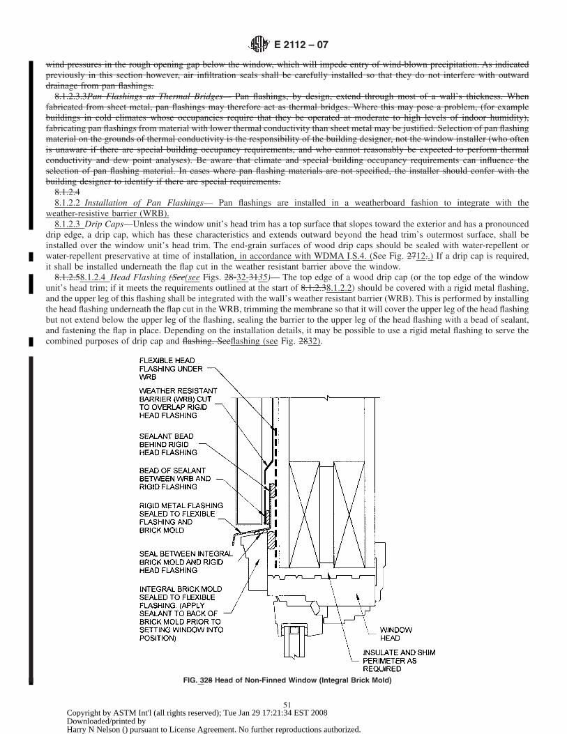
wind pressures in the rough opening gap below the window, which will impede entry of wind-blown precipitation. As indicatedpreviously in this section however, air infiltration seals shall be carefully installed so that they do not interfere with outwarddrainage from pan flashings.
8.1.2.3.3Pan Flashings as Thermal Bridges— Pan flashings, by design, extend through most of a wall’s thickness. Whenfabricated from sheet metal, pan flashings may therefore act as thermal bridges. Where this may pose a problem, (for examplebuildings in cold climates whose occupancies require that they be operated at moderate to high levels of indoor humidity),fabricating pan flashings from material with lower thermal conductivity than sheet metal may be justified. Selection of pan flashingmaterial on the grounds of thermal conductivity is the responsibility of the building designer, not the window installer (who oftenis unaware if there are special building occupancy requirements, and who cannot reasonably be expected to perform thermalconductivity and dew point analyses). Be aware that climate and special building occupancy requirements can influence theselection of pan flashing material. In cases where pan flashing materials are not specified, the installer should confer with thebuilding designer to identify if there are special requirements.
8.1.2.48.1.2.2 Installation of Pan Flashings— Pan flashings are installed in a weatherboard fashion to integrate with the
weather-resistive barrier (WRB).8.1.2.3 Drip Caps—Unless the window unit’s head trim has a top surface that slopes toward the exterior and has a pronounced
drip edge, a drip cap, which has these characteristics and extends outward beyond the head trim’s outermost surface, shall beinstalled over the window unit’s head trim. The end-grain surfaces of wood drip caps should be sealed with water-repellent orwater-repellent preservative at time of installation, in accordance with WDMA I.S.4. (See Fig. 2712..) If a drip cap is required,it shall be installed underneath the flap cut in the weather resistant barrier above the window.
8.1.2.58.1.2.4 Head Flashing (See(see Figs. 28-32-3135)— The top edge of a wood drip cap (or the top edge of the windowunit’s head trim; if it meets the requirements outlined at the start of 8.1.2.38.1.2.2) should be covered with a rigid metal flashing,and the upper leg of this flashing shall be integrated with the wall’s weather resistant barrier (WRB). This is performed by installingthe head flashing underneath the flap cut in the WRB, trimming the membrane so that it will cover the upper leg of the head flashingbut not extend below the upper leg of the flashing, sealing the barrier to the upper leg of the head flashing with a bead of sealant,and fastening the flap in place. Depending on the installation details, it may be possible to use a rigid metal flashing to serve thecombined purposes of drip cap and flashing. Seeflashing (see Fig. 2832).
FIG. 328 Head of Non-Finned Window (Integral Brick Mold)
E 2112 – 07
51Copyright by ASTM Int'l (all rights reserved); Tue Jan 29 17:21:34 EST 2008Downloaded/printed byHarry N Nelson () pursuant to License Agreement. No further reproductions authorized.

8.1.2.68.1.2.5 Trades Responsibility for Drip Cap and Flashing —This practice recommends that drip cap and head flashing beinstalled by the window installers. If these items are not installed by the window installers, the following undesirable events mayoccur: ( 1) water may intrude at the window head before the drip cap and head flashing are installed, (2) the flap in the barrier abovethe window may be damaged by wind or by workers installing or removing fasteners or batten strips used to temporarily secureit. Although it is less than ideal, head flashings are sometimes installed by the cladding system installers. Regardless of which tradegroup installs window head flashing, proper integration of it with the drip cap or window head trim, with the weather-resistivebarrier, and with the cladding system is essential. Special flashing details that are specific to different cladding systems and theirvariations may be necessary (for example, jamb flashings on downhill sides of diagonally-applied wood siding). Such specialflashing details are beyond the scope of this practice.
8.2 Sealant Method: Surface-Sealed Barrier Wall System (Water Contained on Exterior Surface)—In surface sealed systemswater infiltration is prevented at the exterior (outermost) surface. Continuity between wall and fenestration components is attainedby sealant joints. Note that this section does not address projected fenestration products such as bay, bow, or garden windows.
8.2.1 The following guidelines pertain to all openings:8.2.1.1 Rough framing shall be structurally sound and free of damage or deterioration (for example, wood decay).8.2.1.2 Use sealant recommended by the window manufacturer or use a sealant with adequate movement capability and
adhesion to sash or frame and rough opening materials.8.2.1.3 For proper sealant selection follow guidelines in 5.18 and Annex A4.8.2.2 When installing in rough opening (not utilizing an existing frame):
FIG. 29 33 Head Detail of Non-Finned Window (Non-Integral Brick Mold)
E 2112 – 07
52Copyright by ASTM Int'l (all rights reserved); Tue Jan 29 17:21:34 EST 2008Downloaded/printed byHarry N Nelson () pursuant to License Agreement. No further reproductions authorized.

8.2.2.1 Sealant dimensions in the gap between the new frame and opening perimeter should be 1⁄4 3by 1⁄4 in. (6 3by 6 mm)deep minimum. In no case should the sealant depth be greater than its width.
8.2.2.2 Use backer rod to control sealant depth.8.2.3 Installing a replacement product where an existing frame will remain:8.2.3.1 All sash, strips, hardware, and other obstructions shall be removed.8.2.3.2 Existing frames shall be structurally sound and free of deterioration (for example, dry rot).8.2.3.3 See 5.18 for sealant application.8.3 Windows in Walls Utilizing an Exterior Barrier System. (EIFS or Direct Applied)—The EIFS industry is currently revising
details with reference to fenestration products. When complete, those details will be reviewed. Contact the manufacturer of EIFSsystem for details, and fenestration manufacturer for particular EIFS details (see ANSI/EIMA 99-A-2001).
8.4 Special Considerations—Windows should be adequately sealed at the corners in the factory prior to arriving at the job site.Installer should inspect these seals for sealant integrity prior to installation. Reseal according to manufacturer’s instructions, orreject if unable to repair.
8.4.1 Aluminum Framed Windows—Aluminum framed windows do not come from the factory with welded corners, with theexception of some types of casement windows. Special consideration should be given to the joinery of the frames, making surethat they are properly sealed to each other. Make sure when nailing window to a rough opening through a nailing flange, that the
FIG. 304 Common Rigid Head Flashing Details
E 2112 – 07
53Copyright by ASTM Int'l (all rights reserved); Tue Jan 29 17:21:34 EST 2008Downloaded/printed byHarry N Nelson () pursuant to License Agreement. No further reproductions authorized.
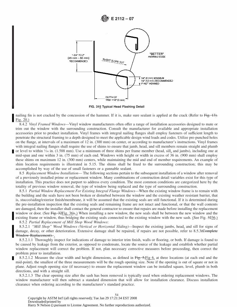
nailing fin is not cracked by the concussion of the hammer. If it is, make sure sealant is applied at the crack (Refer to Fig. 13).Fig. 20.)
8.4.2 Vinyl Framed Windows—Vinyl window manufacturers often offer a range of installation accessories designed to mate ortrim out the window with the surrounding construction. Consult the manufacturer for available and appropriate installationaccessories prior to product installation. Vinyl frames with integral nailing flanges shall employ fasteners of sufficient length topenetrate the structural framing to a depth designed to meet the applicable design wind loads and codes. Utilize pre-punched holeson the flange, at intervals of a maximum of 12 in. (300 mm) on center, or according to manufacturer’s instructions. Vinyl frameswith integral nailing flanges shall require the use of shims to ensure that jamb, head, and sill members remain straight and plumbor level to within 1⁄16 in. (1.588 mm). Use a minimum of three shims per frame member (head, sill, and jambs), including one atmid-span and one within 3 in. (75 mm) of each end. Windows with height or width in excess of 36 in. (900 mm) shall employthese shims on maximum 12 in. (300 mm) centers, while maintaining the mid and end of member requirements. An example ofshim location requirements is illustrated in 5.15. The shims shall be fixed to the surrounding construction; this may beaccomplished by way of the use of small fasteners or a gunnable sealant.
8.5 Replacement Window Installation— The following sections pertain to the subsequent installation of a window after removalof a previously installed prime or replacement window. Many combinations of construction detail variables exist for this type ofinstallation. This practice does not purport to address every condition. The most common conditions are categorized here by thetotality of previous window removal, the type of window being replaced and the type of surrounding construction.
8.5.1 Partial Window Replacement For Existing Integral Flange Windows—When the existing window frame is to remain withthe building and the seals have not been broken or disturbed between the window and the existing weather resistant barrier, thatis, stucco/siding/exterior finish/membrane, it will be assumed that the existing seals are still functional. If it is determined duringthe pre-installation inspection that the existing seals and remaining frame are not intact and functional, or that the wall contentsare damaged, then the installer shall contact the general contractor to ensure that repairs are made before installing the replacementwindow or door. (See Fig. 32Fig. 36)..) When installing a new window, the new seals shall be between the new window and theexisting frame or window, thus bridging the existing seals connected to the existing window with the new sash. (See Fig. 3236.)
8.5.2 Partial Replacement of Mill Shop Wood Windows:8.5.2.1 “Mill Shop” Wood Windows (Vertical or Horizontal Sliding)—Inspect the existing jambs, head, and sill for signs of
damage, decay, or other deterioration. Extensive damage shall be repaired, if repairs are not possible, refer to 8.5.3(CompleteWindow Replacement). .
8.5.2.1.1 Thoroughly inspect for indications of damage to interior trim finish, walls or flooring, or both. If damage is found tobe caused by leakage from the exterior, as opposed to condensate, locate the source of the leakage and establish whether partialwindow replacement will correct the problem. If not, plan necessary corrective measures before proceeding, then correct theproblem prior to installation.
8.5.2.1.2 Measure the clear width and height dimensions, as defined in Fig. 5,Fig 6, at three locations (at each end and themid-point), the smallest of the three measurements will be the rough opening size. Note if the opening is out of square or not inplane. Adjust rough opening size (if necessary) to ensure the replacement window can be installed square, level, plumb in bothdirections, and with a straight sill.
8.5.2.1.3 The clear opening size after the sash has been removed is typically used when ordering replacement windows. Thewindow manufacturer will then subtract a standard dimension that will allow for installation clearance. Discuss installationclearance when ordering according to the manufacturer’s standard practice.
FIG. 315 Typical Head Flashing Detail
E 2112 – 07
54Copyright by ASTM Int'l (all rights reserved); Tue Jan 29 17:21:34 EST 2008Downloaded/printed byHarry N Nelson () pursuant to License Agreement. No further reproductions authorized.

8.5.2.1.4 Ensure that the replacement window is the correct size and type for the opening, including tolerances and provisionsfor adjustments to out of square, plumb, or level.
8.5.2.1.5 If a storm window is present, first remove glass and screen panels, then carefully disconnect storm frame from windowframe.
8.5.2.1.6 Score the joints, and then remove the interior sash stops from the jambs and head. Use special care when removingthese stops if they are to be reinstalled after window installation (optional). See(optional) (see Fig. 3339).
8.5.2.1.7 Disconnect the sash from balances (if employed), remove the interior sash. Remove parting stop, disconnect the sashfrom balances (if employed), remove the exterior sash (See(see Fig. 3440). The glass in fixed lites may need to be broken in orderto remove, (always wear safety glasses and gloves) place drop cloths at the interior and exterior to catch the debris.(Warning—Some balancing devices may move rapidly and with great force when the weight of the sash is removed. Care shallbe exercised to avoid serious injury.)
8.5.2.1.8 Remove remaining balance assemblies. Fill any large holes with insulation. Replace any unsound material. Removedebris. Use a carpenter’s level to determine if the sill is level, apply shims as necessary to support the replacement sill in a levelposition at a minimum of three points.
8.5.2.1.9 Un-package the replacement window, remove the sash and screen from the frame (if possible). Set the frame into theopening against the exterior stops to confirm fit and to determine if a head expander or sill angle accessories, or both, are required.A head expander will be required if the head does not contact the top exterior stop. Measure the sill gap as illustrated in Fig. 35Fig.41, a sill angle will be required if the sill gap exceeds 1⁄8 in. (3 mm). Mark the sill angle location (if required) on the wood sill.Remove the frame.
8.5.2.1.10 If a sill angle accessory is required, place a bead of sealant along the length of the lower face and fasten to the sillon marks with a minimum of three fasteners as illustrated in Fig. 35Fig. 41. Apply breakable cladding to exposed exterior surfacesas necessary. Place a 1⁄4 in. (6 mm) bead of sealant around the interior face of the exterior stops, and (if employed) across the topof the exterior face of the sill angle upturned leg (see Fig. 35Fig. 41).
8.5.2.1.11 Newly exposed surfaces of components of original window installation require protection from weathering. Suchprotection may consist of painting, panning, or break metal cladding.
8.5.2.1.12 Mount the head expander (if employed) to the window creating the minimum height. Place the window frame in the
FIG. 326 Partial Window Replacement Detail Flush Fin or Stucco Flange (Sill Detail Shown-—Jambs and Head Similar)
E 2112 – 07
55Copyright by ASTM Int'l (all rights reserved); Tue Jan 29 17:21:34 EST 2008Downloaded/printed byHarry N Nelson () pursuant to License Agreement. No further reproductions authorized.

opening on the sill shims (if employed) and against the sealant on the exterior stops. The sill angle shall align behind thedown-turned exterior sill leg as illustrated in Fig. 35Fig. 41. Square the frame using a carpenter’s square.
8.5.2.1.13 Install the number, type, and size fasteners at the locations prescribed by the manufacturer for this sized windowmodel and location. Adjust the fasteners to create and hold window squareness while maintaining frame load bearing on the sillor sill shims. Do not over-tighten the fasteners.
8.5.2.1.14 Install the sash and screen, then check for proper operation, locking, and fit. Make adjustments to fasteners orhardware as necessary.
8.5.2.1.15 If a head expander accessory is employed, slide the expander up for maximum contact with the sealant, then secure
FIG. 5 37 Measuring Replacement Openings
FIG. 38 Check for Racking
E 2112 – 07
56Copyright by ASTM Int'l (all rights reserved); Tue Jan 29 17:21:34 EST 2008Downloaded/printed byHarry N Nelson () pursuant to License Agreement. No further reproductions authorized.

to the replacement window head according to the manufacturer’s instructions. If a sill angle accessory was not employed, seal thefull width of the sill to the sill construction with a bead of sealant. Fill the frame web perimeter voids with insulation. Install interiortrim accessory parts or reinstall the interior sash stops removed according to Fig. 33Fig. 39. If neither option is available thenmeasure, cut, install and finish new interior sash stops.
8.5.2.1.16 Insulate the voids between replacement and existing framing members in accordance with 5.9.2.8.5.2.2 Wood Windows Containing Frame Liners (Vertical or Horizontal Sliding)—Inspect the existing wood jambs, head, and
sill for signs of damage, decay, or other deterioration. Also measure the interior to exterior jamb depth without the liners andexterior stop size/location to determine if the replacement window will mate with the existing frame. If a partial replacement isnot feasible or if damage cannot be repaired, refer to 8.5.3—Complete Window Replacement.
8.5.2.2.1Thoroughly inspect for indications of damage to interior trim finish, walls, or flooring, or a combination thereof. Ifdamage is found to be caused by leakage from the exterior, as opposed to condensate, locate the source of the leakage and establishwhether partial window replacement will correct the problem. If not, plan necessary corrective measures before proceeding, thencorrect the problem prior to installation.
8.5.2.2.2Carefully remove the interior trim and stops to reveal the jamb to jamb and head to sill dimensions without the liners.Measure the clear width and height dimensions, at three locations (at each end and the mid-point), the smallest of the threemeasurements will be the rough opening size. Note if the opening is out of square or not in plane. Adjust rough opening size (ifnecessary) to ensure the replacement window can be installed square, level, plumb in both directions, and with a straight sill. SeeFig. 6.
8.5.2.2.1 Thoroughly inspect for indications of damage to interior trim finish, walls, or flooring, or a combination thereof. Ifdamage is found to be caused by leakage from the exterior, as opposed to condensate, locate the source of the leakage and establishwhether partial window replacement will correct the problem. If not, plan necessary corrective measures before proceeding, thencorrect the problem prior to installation.
8.5.2.2.2 Carefully remove the interior trim and stops to reveal the jamb to jamb and head to sill dimensions without the liners.
FIG. 339 Window Replacement-Bottom Sash Removal (Inside-Out Method)
E 2112 – 07
57Copyright by ASTM Int'l (all rights reserved); Tue Jan 29 17:21:34 EST 2008Downloaded/printed byHarry N Nelson () pursuant to License Agreement. No further reproductions authorized.

Measure the clear width and height dimensions, at three locations (at each end and the mid-point), the smallest of the threemeasurements will be the rough opening size. Note if the opening is out of square or not in plane. Adjust rough opening size (ifnecessary) to ensure the replacement window can be installed square, level, plumb in both directions, and with a straight sill (seeFig 13).
8.5.2.2.3 The clear opening size after the sash is removed is typically used when ordering replacement windows, the windowmanufacturer will then subtract a standard dimension that will allow for installation clearance. Discuss installation clearance whenordering according to the manufacturer’s standard practice.
8.5.2.2.4 Remove the sash. The glass in fixed lites may need to be broken in order to remove, (always wear safety glasses andgloves) place drop cloths at the interior and exterior to catch the debris. Carefully remove the frame liners in a manner that willminimize damage to the remaining frame. Remove all liner fasteners, and clear the rough opening of obstructions or protrusionsthat would interfere with the installation of the replacement window.
8.5.3 Complete Window Replacement—For complete window replacement, remove the existing window in a manner that willminimize damage to the remaining construction. Remove all window fasteners, and clear the rough opening of obstructions orprotrusions that would interfere with the installation of the replacement window. If felts or other protective membrane aredisturbed, patch all damaged areas with appropriate materials so as to maintain continuity of the water barrier. Avoid damagingany existing flashings inside the wall. Where existing openings are re-framed to a smaller size, insulate the voids between framingmembers and the window, and provide air barriers to control air movement. For cold climates, install a vapor retarder on the warmside of the installation. Provide interior and exterior coverings compatible with existing construction. Where new felts (or otherbuilding paper materials) are installed, place the new felts under the existing felts in shingle fashion, so as to shed water to theoutside. Where two or more windows are installed in a horizontal series, provide appropriate blocking, gusset plates, or studsbetween the windows. Extend head flashings to cover exposed joints between adjacent windows. For clad windows in a series,install exterior trim strips between windows, and cover the exposed top with appropriate flashing accessories. Do not installmultiple windows without adequate intermediate supports to resist loads perpendicular to the plane of the windows. Where two
FIG. 3 40 Window Replacement-Top Sash Removal (Inside-Out Method)
E 2112 – 07
58Copyright by ASTM Int'l (all rights reserved); Tue Jan 29 17:21:34 EST 2008Downloaded/printed byHarry N Nelson () pursuant to License Agreement. No further reproductions authorized.

or more windows are stacked vertically or mulled horizontally, consult the manufacturer’s recommendations to ensure that the typeof window used is appropriate for such stacking or mulling. Provide appropriate flashings to prevent leakage.
8.5.3.1 Destructive Window Replacement (Fin Type)—Destructive window replacement shall be accomplished by removal ofthe original window product and the carefully planned removal of building veneers with minimal damage to the surroundingveneers or framing. The removal of the building veneer is required to facilitate the installation of the new window product usingan anchoring fin under the exterior veneer.
8.5.3.1.1 Remove the perimeter sealant both on the inside and outside perimeter edges of the installed window. Exercise careto avoid damage to the exterior and interior finished veneered surfaces. Wherever possible, sealant shall be cut away, not pulledfrom the opening with attendant possible damage to the surround.
8.5.3.1.2 Disengage the anchoring components of the window from the surrounding support framework. If the window wasanchored through the window frame with fasteners which passed into the support framework, these fasteners shall be carefully cutthrough or removed starting at the bottom of the window and working upward. If the window was anchored with an anchoringfin, it shall be exposed by removal of the exterior building veneer(s) prior to disengaging the anchoring fasteners. Removal of theveneer(s) shall be planned so as to minimize damage to the veneer and the building’s exterior appearance.
8.5.3.1.3 Exercise care to temporarily support the window product so that it does not suddenly fall from the opening, possiblyendangering the technician and damaging the surrounding veneers.
8.5.3.1.4 Ideally, the replacement of mounting flange windows would allow for the use of 9 in. (230 mm) wide flashingmaterials as required in new construction installation. Due to aesthetic reasons, however, this would require a much wider cut thanmight be acceptable to the building owner. Whenever it is practical to remove the exterior facade to allow for 9 in. (230 mm) wideflashing, the installer should do so, but in cases where the homeowner insists on limitingdecision has been made to limit the amountof removal, the cutout can be reduced to a 3 in. (75 mm) minimum. When reducing the cutout to 3 in. (75 mm), the use of 4 in.(100 mm) wide (min.) self-adhesive flashing is required.
8.5.3.1.5 The veneer shall either be cut back from the opening using a sharp utility knife or saw; or in the case of discreet veneercomponents, removal of the components one at a time. The veneer shall be cut back a minimum of 3 in. (75 mm) or a distanceto permit the installation of perimeter flashing and weathering materials using the following steps.
8.5.3.1.6 Remove the window product from the opening and set it aside for later disposal. Carefully examine the openingcreated by removal of the original window product. If there has been damage or deterioration of the supporting framework eitherdue to the removal process or to the effects of weathering of the old installation, this damage shall be repaired before installationof the new replacement window is attempted. The supporting framework shall be structurally sound prior to continuing with thisinstallation.
8.5.3.1.7 In the event that portions of the weather resistant barrier were cut out during window removal (for example, cuttingout around mounting flange windows), the installer should replace the weather resistant barrier. This can be accomplished bylapping a new piece of material over the remaining weather resistant barrier. The new piece of material should overlap the existingby a minimum of 1 in. (25 mm). Additionally, the overlapping edge should be sealed or taped to the existing material (for example,sealant in the case of building paper or taped in the case of house wrap).
FIG. 35 41 Window Replacement-Sill Extender/Sill Angle Installation
E 2112 – 07
59Copyright by ASTM Int'l (all rights reserved); Tue Jan 29 17:21:34 EST 2008Downloaded/printed byHarry N Nelson () pursuant to License Agreement. No further reproductions authorized.

8.5.3.1.8 Building air barriers and exterior veneer under-sheathing shall be restored prior to commencing installation of the newwindow. The window opening shall be returned to at least the condition as originally constructed, prior to installation of the newproduct.
8.5.3.1.9 In some applications, it is possible that the installer can remove the existing window without causing any damage,leaving the existing flashing or weather resistant barrier, or both, materials in good condition. When this occurs, the installer canreuse the existing materials and reset the window.
8.5.3.1.10 After the completion of previous steps, the replacement window shall be installed and sealed as a new windowproduct with perimeter installation fins. This installation process shall be accomplished according to the procedures outlined asfollows.
8.5.3.1.11 When the exterior facade has been removed to allow for the installation of a full 9 in. (230 mm) piece of flexibleflashing, the installation process will be treated much like installing a mounting flange in new construction. New mounting flangewindow installation instructions are outlined in 8.1, and will depend on the existing materials and the method selected.
8.5.3.1.12 When the cutout is smaller than 9 in. (230 mm) (3 in. (75 mm) minimum), new self-adhesive type flashing materials(4 in. (100 mm) minimum) can be used to integrate the existing weather resistant barrier and mounting flange together. Theinstallation process used will be similar to new installation Method A1, assuming the existing weather resistant barrier is in place.In cases where the cutout is less than 9 in. (230 mm), the procedure follows.
8.5.3.1.13 Once the window is removed and repairs have been made to the existing weather resistant barrier, flashing is appliedat the sill condition. In the event that the existing flashing is in good condition and is being reused, proceed with windowinstallation.
8.5.3.1.14 When flashing has been removed or does not exist, apply a piece of self-adhesive sill flashing level with the top ofthe rough opening directly over the weather resistant barrier at the sill condition.
8.5.3.1.15 Prior to installing the window, cut a flap in the weather resistant barrier at the head. The cut will be from the cornerof the rough opening to the corner of the cutout in the facade, at approximately 45°. Raise the flap up and tape it out of the way,allowing for the installation of the new window and the jamb flashing.
8.5.3.1.16 Seal and install the mounting flange replacement window according to the instruction outlined in 8.1 for Method A1.This process will include the sealing of the entire back side of the mounting flange prior to installation.
8.5.3.1.17 After the window is installed, apply a piece of self-adhesive flashing over the face of the mounting flange at eachjamb. See 5.12.3.1. Place the jamb flashing under the flap in the weather resistant barrier at the head, and over the sill flashing inweather-board fashion. When required by the flashing manufacturer, allow the sealant to cure prior to flashing installation, as someflashing materials are not to come into contact with solvent-release sealants.
8.5.3.1.18 Apply the self-adhesive flashing over the mounting flange at the head. The head flashing will be installed similar tothe jamb flashing, except the head flashing will be placed completely under the flap of the weather resistant barrier at the head.
8.5.3.1.19 After the window is properly positioned, sealed, flashed, and securely fastened in place, finish the opening byapplying rigid head flashing, blocking, casing/trim, and perimeter seals as required.
8.5.3.1.20 Install blocking (filler strips) into the void that was cut out when removing the old window. The blocking should beflush with the exterior face of the façade.
NOTE46—Tip: 53—Tip: When removing wood siding, the old materials can be reused to fill the gap.
8.5.3.1.21 Apply new exterior casing/trim over the cutout made in the facade. In the case of a 3 in. (75 mm) minimum cutout,a new piece of 1 3 4 can be used to trim the opening. When reapplying trim, leave a minimum of a 1⁄4-in. (6-mm) joint aroundthe perimeter of the window to allow for the application of a perimeter sealant joint.
8.5.3.2 Non-Destructive Window Replacement (Non-Fin Type) —Non-destructive window replacement shall be accomplishedby removal of the original window product without significant damage to the surrounding building veneers or framing.
8.5.3.2.1 Remove the perimeter sealant both on the inside and outside perimeter edges of the installed window. Exercise careto avoid damage to the exterior and interior finished veneered surfaces. Wherever possible, sealant shall be cut away, not pulledfrom the opening with attendant possible damage to the surround.
8.5.3.2.2 Disengage the anchoring components of the window from the surrounding support framework. If the window wasanchored through the window frame with fasteners which passed into the support framework, these fasteners shall be carefully cutthrough or removed starting at the bottom of the window and working upward. If the window was anchored with an anchoringfin, the fin shall be cut through as close to the surface of the supporting framework as possible. This may be accomplished utilizinga sharp utility knife or a saw such as a reciprocating cut-off saw. Exercise care to temporarily support the window product so thatit does not suddenly fall from the opening, possibly endangering the installer and damaging the surrounding veneers.
8.5.3.2.3 Remove the window product from the opening and set it aside for later disposal.8.5.3.2.4 Carefully examine the opening created by removal of the original window product. If there has been damage or
deterioration of the supporting framework either due to the removal process or due to the effects of weathering of the oldinstallation, this damage shall be repaired before installation of the new replacement window is attempted. The supportingframework shall be structurally sound prior to continuing with this installation.
8.5.3.2.5 After the completion of steps 8.5.2.1 and 8.5.3, the replacement window shall be installed and sealed as a new window
E 2112 – 07
60Copyright by ASTM Int'l (all rights reserved); Tue Jan 29 17:21:34 EST 2008Downloaded/printed byHarry N Nelson () pursuant to License Agreement. No further reproductions authorized.

product in a punched opening. This installation shall be accomplished according to the procedures outlined in 8.1.2 for non-finnedwindows.
9. Installation Methods for Doors
9.1 Doors in Walls Utilizing a Membrane/Drainage System:9.1.1 Doors with Perimeter Mounting Flanges (Nailing Fins) in Drainage Type Wall Construction:9.1.1.1 Doors with perimeter mounting flanges shall be installed with flashing sheets, which shall be applied so as to integrate
with the flanges on the door unit and with the weather resistant barrier materials in a shingle-lap manner. Four different methods(A, B, A1, and B1) may be used. These methods are described in this section.
9.1.1.1.1 Not all mounting flanges are considered structural by the manufacturer; however, they still are to be integrated intothe wall using the following procedures. Mounting flanges are classified into the following categories:
(1) Integral, structural mounting flanges(2) Integral, non-structural mounting flanges(3) Applied, structural mounting flanges(4) Applied, non-structural mounting flanges.
9.1.1.1.2 In this classification scheme, integral implies permanence, continuity, seamless, and waterproof. Applied mountingflanges may require more elaborate flashing and sealing details to ensure weather protection of the installed unit. When usingapplied mounting flanges, follow the manufacturer’s instructions for sealing the flange to the frame.
9.1.1.1.3 Structural implies that the mounting requirements of the fenestration unit in its location intransfer the load from thewindow frame to the building. Non-structural flanges will require different anchoring methods to ensure the integrity of theinstallation. When using non-structural mounting flanges, follow the manufacturer’s instructions for proper anchoring of thefenestration product.
9.1.1.1.4 Additionally, doors are often shipped to the job site (KD) or knocked down for field assembly. If the doors arepre-assembled, manufacturers often suggest removing the operable panels for ease of installation. Numerous references to theinstallation of the door (or door frame) are used in these instructions. As a point of clarification, the use of the terms door, and doorframe are interchangeable.
9.1.1.2 Selection of an installation method (A, B, A1, or B1) is based on the relative order in which materials are installed, andon whether the pieces of flashing sheet used alongside the door (the jamb sheets) are applied over or behind the door unit’s sideflanges. Doors with mounting flanges may be installed either before or after the weather-resistantweather-resistive barrier (WRB).Although door installers often do not install the weather resistant barrier, the door installation shall be integrated properly with themembrane. To avoid confusion between membrane-installation and door-installation crews, it is recommended that the relativeorder of their work be identified in advance and that the identified order be maintained for either an entire project or for clearlydemarcated portions of the project. This will allow selection of an installation method for the project, and help eliminate errorscaused by installers having to switch between methods. Once a method is selected, all of the procedures of that method shall beperformed in the sequence indicated. Never mix or match methods or alter the sequence of operations within a method.
9.1.1.2.1 The references to the application of sealant under or over the mounting flanges refer to the use of Bedding Joints . Abedding joint consists of the application of a bead of sealant which is later compressed against the substrate or flashing materials.All bedding joints are to have a nominal diameter of 3⁄8 in. (10 mm) prior to compression. During compression of a bedding joint,the installer should look for the sealant to squeeze out or appear along the closest edge to ensure adequate bedding quality.
9.1.1.2.2 Use the flashing cut formulas (see Table 67) to determine the length of each strip of flashing for each window. TheASTM standard This practice requires a flexible flashing minimum roll width of 9 in. (230 mm). Wider flashing materials, (forexample, 12 in. (300 mm)) may be used, however the actual cut lengths figured by using the chart will increase. The use ofself-adhesive type flashing is acceptable. Use of self-adhered flashings in widths other than 9 in. (230 mm) shall be permitted whenaccepted in writing by the window manufacturer and the flashing manufacturer, or specified by the design professional.Self-adhesive type flashing seals itself to the weather resistant barrier and to the mounting flange without the need for additionalsealant. A continuous bead of sealant shall be applied to the back side of the mounting flange prior to placing the window.Self-adhesive type flashing materials must properly adhere, (creating a water tight joint) to the WRB and to the mounting flangematerial in order to be acceptable for use. Referuse (refer to 5.12.3.1. (). (Warning—All notations of sealant placement, (forexample, 81⁄2 in. (220 mm) up and 81⁄2 in. (220 mm) over) are based on the use of a 9 in. (230 mm) wide flashing.)
NOTE47—Tip: 54—Tip: In order to save time and develop an efficient installation process, the flashing materials can be cut in advance using the roughopening dimensions and the formulas shown in the table below. Cutting flashing in advance also reduces the chance for the sealant to skin over prior tothe application of flashing. The instructions in the installation section of this chapter assume that the flashing is previously cut to the appropriate length.
9.1.1.3 Table 8Table 9 can be used to select the appropriate installation method.9.1.1.4 The following procedures should be followed completely and finished the day the procedure starts in order to avoid
damage to the flashing and weather resistant barrier (WRB). If it is impossible to finish the complete process, the loose ends ofthe flashing and WRB shall be temporarily secured using tape. The building contractor is responsible for the coordination of thiswork, as it is greatly dependent on the construction schedule. Once installed, local wind and weather conditions as well as exposureto other trades can have a detrimental effect on the permanent attachment of flashing. The building contractor must inspect and
E 2112 – 07
61Copyright by ASTM Int'l (all rights reserved); Tue Jan 29 17:21:34 EST 2008Downloaded/printed byHarry N Nelson () pursuant to License Agreement. No further reproductions authorized.

maintain the flashing, insuring it is secure and in proper condition prior to being covered up by other materials.
NOTE48—All 55—All methods described below require the use of a 9 in. (230 mm) (minimum) wide approved flashing material. Flashing cut lengthsare to be increased respectively depending on the actual width of the flashing used on the job. Flashing is always to be lapped in a water shedding (weatherboard, shingle, or ship-lapped) fashion.
9.1.1.4.1 Method A: Weather-ResistantWeather-Resistive Barrier (WRB) Applied after the Door Installation—Flashing AppliedOver the Face of the Mounting Flange:
9.1.1.4.1.1 Step 1: Assumes mounting flange on door sill. (Go to Step 1a or 1b for pan flashings or sealant onlymethod).method.) Apply the horizontal sill flashing material first, level with the top edge of the rough opening. Cut the sill flashinglong enough to extend an equal distance beyond the 9 in. (230 mm) jamb flashing, which will be applied later. (See Fig. 3613)..)Fasten the top edge of the sill flashing to the framing. Place fasteners along the edge of the rough opening where they will becovered by the mounting flange of the door later.
NOTE49—Do 56—Do not fasten the bottom edge or the last 9 in. (230 mm) of each end, as the weather resistant barrier will be applied under theflashing in a water shedding fashion later. It is recommended that the corners and bottom edge be temporarily taped at 24 in. (610 mm) on center, toprevent wind damage.
9.1.1.4.1.2 Step 1a. Assumes no sill mounting flange on bottom of door sill or use of pan flashing. Apply continuous sealantbeads across the full floor length of the framed opening (or along the bottom of the door frame) in a location where the floor makescontact with the door sill. Two 3⁄8 in. (10 mm) diameter beads shall be used. Deposit a sufficient amount of the sealant at the framedopening corners so the bottom door frame corners are embedded in sealant when the door is installed. See 5.18 for sealant selectionand use.
NOTE50—All 57—All surfaces contacting sealant shall be free of dust and dirt prior to application of sealant. Sealant used shall be compatible withsubstrates both chemically and adhesively. Seeadhesively (see Annex A4. ).
9.1.1.4.1.3 Step 1b. Assumes no sill mounting flange, but uses pan flashing across the threshold. Apply two beads of sealant asnoted in 1a above. Then apply a continuous pan flashing along full width of rough opening. Make sure each end of pan flashingis end dammed. See 5.16 through 5.16.2. Inside of pan flashing shall have an upturned leg at a height selected from through 5.16.5.If the door is not sealed to the pan flashing with an air-infiltration seal, then the inside of pan flashing shall have an upturned legat a height selected from Annex A3, depending on door rating or grade used.
9.1.1.4.1.4 Step 2: Apply a continuous bead of sealant to the back side (interior surface) of the mounting flange of the door.Sealant selection and bead design shall be in accordance with 5.18 of the installation procedures. Immediately set the door intothe opening, apply shims as required to ensure the unit is plumb, level and square. Fasten the door perimeter securely into positionas described in 5.14 and 5.15 in the Related Procedures Section.
NOTE51—Apply 58—Apply the sealant in line with the pre-punched holes or slots on the mounting flange when provided (See(see Fig. 3742). Referto 5.12.3.1.
9.1.1.4.1.5 Step 3: Next, apply a continuous bead of sealant to the exposed jamb mounting flanges (exterior surface) at the sidejambs of the installed door. Continue the sealant bead at the jambs vertically 8-1⁄2 in. (220 mm) above the rough opening at thehead of the door (to the face of the header), to allow for application of the top portion of the jamb flashing into sealant in the nextstep.
NOTE52—Apply 59—Apply the sealant in line with the pre-punched holes or slots on the mounting flange when provided and over the heads of thefasteners. Refer to 5.12.3.1. . Where a pan flashing is used, the bead of sealant at the sill must have discontinuity in order to permit drainage from thesill pan to the exterior or drainage plane. See note after section 5.18.8 for further explanation.
9.1.1.4.1.6 For doors with mechanically joined mounting flanges, apply sealant to the full length of the joints or seam wherethe mounting flanges meet the door frame and at the corner joints. (See Fig. 37). Fig. 42.)
9.1.1.4.1.7 Step 4: Install the jamb flashings next, by pressing them into the sealant beads previously applied to the exterior faceof the mounting flanges. Attach the flashing to the sheathing surrounding the rough opening using staples or other appropriate
TABLE 8 9 Installation Procedure Selection Chart (Doors)
NOTE 1—Based on doors with mounting fins being installed in drainage type wall systems.
Procedure Method Method
Head and jamb flashing will be applied overthe face of the integral mounting flange
Jamb and sill flashing will be applied behindthe face of the integral mounting flange
Weather resistant barrier is to be appliedafter door installation
Use Method A Use Method B
Weather resistant barrier is to be appliedafter door installation
use Method A use Method B
Weather resistant barrier is to be appliedprior to door installation
Use Method A1 Use Method B1
Weather resistant barrier is to be appliedprior to door installation
use Method A1 use Method B1
E 2112 – 07
62Copyright by ASTM Int'l (all rights reserved); Tue Jan 29 17:21:34 EST 2008Downloaded/printed byHarry N Nelson () pursuant to License Agreement. No further reproductions authorized.

fasteners. Extend the bottom edge of the jamb flashing 8-1⁄2 in. (220 mm) beyond the rough opening sill, and extend the top edge8-1⁄2 in. (220 mm) beyond the rough opening head. (See Fig. 38Fig. 43). .)
NOTE53—Do 60—Do not attach the bottom of the jamb flashing until after the weather resistant barrier is applied later.
9.1.1.4.1.8 Step 5:. Next apply a continuous bead of sealant to the exposed mounting flange (exterior surface) at the head ofthe installed door.
NOTE54—Apply 61—Apply the sealant in line with the pre-punched holes or slots in the mounting flange when provided and over the heads of thefasteners. (See Fig. 3944)..) The application of sealant to the flange is not necessary if using self-adhesive type flashing over the mounting flange.
9.1.1.4.1.9 Step 6: Install the head flashing by pressing the flashing into the sealant beads previously applied across themounting flange and 8-1⁄2 in. (220 mm) above it. Press the bottom and top edges of the flashing into the sealant until it squeezesout at the edges of the flashing. This will ensure that no voids remain between the flashing and the mounting flange and betweenthe flashing and the WRB. Extend the ends of the head flashing 10 in. (250 mm) beyond the rough opening, over the top of thejamb flashing. Fasten the head flashing along the top edge using staples or other appropriate fasteners. (Seefasteners (see Fig.4045). (Warning—The building shall be constructed in a manner to secure or support the flashing to prevent destruction ordisplacement prior to installation of the weather resistant barrier. The flashing shall never be left unsupported and vulnerable towind damage.)
NOTE55—When 62—When used as part of the exterior wall system, install the weather resistant barrier as outlined below. Note that the applicationof the weather resistant barrier may be by trades other than the door installer. The contractor shall coordinate this work as required.
9.1.1.4.1.10 Step 7: When building paper is used, in water shedding fashion, starting at the base of the wall and working towardsthe top, install it onto the face of the building framing or sheathing. At the sill of the doors, tuck the building paper under the sillflashing and lower ends of the jamb flashing. Next, continue to apply the building paper in water shedding fashion over the jambflashing and over the head flashing of the doors. (Seedoors (see Fig. 4146). Attach the building paper to the sheathing using staplesor other appropriate fasteners.
9.1.1.4.1.11 Step 7a: When one piece weather resistant barrier is used, install it under the sill flashing and over the jamb andhead flashings as described above for building paper installation.
NOTE 1—For Method A1 the weather resistant barrier (WRB) has been installed. A flap at the head of the window has been temporarily taped out ofthe way to allow for flashing and door installation.
FIG. 37 42 Apply Sealant Over Mounting Flange at Jambs (Method A)
E 2112 – 07
63Copyright by ASTM Int'l (all rights reserved); Tue Jan 29 17:21:34 EST 2008Downloaded/printed byHarry N Nelson () pursuant to License Agreement. No further reproductions authorized.

NOTE 563—Whenever applying the weather-resistantweather-resistive barrier, flashing, or other materials do not penetrate the mounting flange withthe fasteners.
9.1.1.4.2 Method B: Weather-ResistantWeather-Resistive Barrier (WRB) Applied after the Door Installation—Flashing AppliedBehind the Face of the Mounting Flange:
9.1.1.4.2.1 Step 1: Assumes mounting flange on door sill. Go to step 12 or 16 for pan flashings or sealant-only method. Applythe horizontal sill flashing material first, level with the top edge of the rough opening. Cut the sill flashing long enough to coverthe 9 in. (230 mm) jamb flashing, which will be applied later. (Seelater (see Fig. 3613). Fasten the top edge of the sill flashing tothe framing. Place fasteners along the edge of the rough opening where they will be covered by the mounting flange of the doorlater.
NOTE57—Do 64—Do not fasten the bottom edge of the sill flashing or the last 9 in. of each end, as the weather resistant barrier will be applied underthe flashing in a water shedding fashion later. It is recommended that the corners and bottom edge be temporarily taped at 24 in. (600 mm) on center,to prevent wind damage.
9.1.1.4.2.2 Step 1a.1a: Assumes no sill mounting flange or use of pan flashing. Apply continuous sealant beads across the fullfloor length of the framed opening (or along the bottom of the door frame) at a location that will make contact with the door sill.Two 3⁄8 in. (10 mm) diameter beads should be used. Deposit a sufficient amount of the sealant at the framed opening corners sothe bottom door frame corners are embedded in sealant when the door is installed. Seeinstalled (see 5.18. ).
NOTE58—All 65—All surfaces contacting sealant shall be free of dust and dirt prior to application of sealant. Sealant used shall be compatible withsubstrates both chemically and adhesively. See Annex A4.
9.1.1.4.2.3 Step 1b.1b: Assumes no sill mounting flange, but uses pan flashing across the threshold. Apply two beads ofcontinuous sealant as noted in 1a above.Step 1a. Then apply a continuous pan flashing along full width of rough opening. Makesure each end of pan flashing is end dammed. See 5.16 through 5.16.2. Inside The inside of pan flashing must have anair-infiltration seal or an upturned leg at a height selected from Annex A3, depending on door rating or grade used.
9.1.1.4.2.4 Step 2: Apply the jamb flashing to the edge of the framing at each jamb. Place fasteners along the edge of the roughopening where they will be covered by the jamb mounting flange of the door later. Extend the jamb flashing 8-1⁄2 in. (220 mm)beyond the rough opening at the head and sill. The bottom end of the jamb flashing must overlap the sill flashing.
NOTE59—Do 66—Do not attach the bottom of the jamb flashing until the weather resistant weather-resistive barrier is applied later. (See Fig. 4146.)
9.1.1.4.2.5 Step 3: Apply a continuous bead of sealant around the full perimeter of the back side (interior surface) of the doormounting flanges. Sealant selection and bead design shall be in accordance with 5.18 of the installation procedures.
NOTE 1—For Method A1, the weather resistant barrier (WRB) has been installed. A flap at the head of the window has been temporarily taped out ofthe way to allow for flashing and door installation.
FIG. 438 Application of Jamb Flashing (Method A)
E 2112 – 07
64Copyright by ASTM Int'l (all rights reserved); Tue Jan 29 17:21:34 EST 2008Downloaded/printed byHarry N Nelson () pursuant to License Agreement. No further reproductions authorized.

NOTE60—Apply 67—Apply the sealant in line with the pre-punched holes or slots on the mounting flange when provided. Alternatively, you may sealaround the entire perimeter of the opening at the location where the back side (interior surface) of the mounting flange will make contact with theperimeter seal. (See Fig. 4247)
9.1.1.4.2.6Step 4: Immediately install the door into the opening pressing the door against the framing to compress the sealant.Apply shims as required to ensure the unit is plumb, level and square. Fasten the door perimeter securely into position as describedin .) Where a pan flashing is used, the bead of sealant at the sill must have discontinuity in order to permit drainage from the sillpan to the exterior or drainage plane. See note after section 5.18.8 for further explanation.
9.1.1.4.2.6 Step 4: Immediately install the door into the opening pressing the door against the framing to compress the sealant.Apply shims as required to ensure the unit is plumb, level, and square. Fasten the door perimeter securely into position as describedin 5.14 and 5.15 of the installation procedures.
NOTE 618—Exercise caution to avoid disrupting the continuous seal. Always install the door immediately after the application of the sealant.
For doors with mechanically joined mounting flanges, apply sealant to the full length of the joinery or seam where the flangesmeet. (Seemeet (see Fig. 2127).
9.1.1.4.2.7 Step 5: Apply a continuous bead of sealant horizontally across the face of the header at the top of the door roughopening and a continuous bead of sealant to the exposed mounting flange (exterior surface) at the head of the installed door. Thesealant bead on the header should be placed in line with the top of the jamb flashing (8-(81⁄2 in. (220 mm) above the rough opening),so the top of the head flashing can be pressed into the sealant in the next step. Continue the sealant bead over the top edge (exteriorside) of the jamb flashing in order to fully integrate the head and jamb flashing together. (Seetogether (see Fig. 3944).
NOTE62—Apply 69—Apply the sealant in line with the pre-punched holes or slots in the mounting flange when provided and over the heads of thefasteners. (Seefasteners (see Fig. 4348). The application of sealant to the flange is not necessary if using self-adhesive type flashing over the mountingflange.
9.1.1.4.2.8 Step 6: Install the head flashing by pressing the flashing into the sealant beads previously applied to the headmounting flange and 8-81⁄2 in. (220 mm) above the rough opening. Press the bottom and top edge of the flashing into the sealant
NOTE 1—For Method A1, the weather resistant barrier (WRB) has been installed. A flap at the head of the window has been temporarily taped out ofthe way to allow for flashing and door installation.
FIG. 39 44 Application of Sealant to Mounting Flange at Head (Method A)
E 2112 – 07
65Copyright by ASTM Int'l (all rights reserved); Tue Jan 29 17:21:34 EST 2008Downloaded/printed byHarry N Nelson () pursuant to License Agreement. No further reproductions authorized.

until it squeezes out at the edges of the flashing. This will ensure that no voids remain between the flashing and the header ormounting flange, which could potentially admit and trap water behind the flashing. Extend the ends of the head flashing 10 in. (250mm) beyond the rough opening, over the top of the jamb flashing. Fasten the head flashing into place along the top edge usingstaples or other appropriate fasteners. (Seefasteners (see Fig. 4045). (Warning—The building shall be constructed in a manner tosecure or support the flashing to prevent its destruction or displacement prior to installation of the weather resistant barrier. Theflashing shall never be left unsupported and vulnerable to wind damage.)
NOTE63—When 70—When used as part of the exterior wall system, install the weather resistant barrier as outlined below. Note that the applicationof the weather resistant barrier may be by trades other than the door installer. The contractor shall coordinate this work as required.
9.1.1.4.2.9 Step 7: When building paper is used, in water shedding fashion, starting at the base of the wall and working towardsthe top, install it on to the face of the building framing or sheathing. At the sill of the doors, tuck the building paper under the sillflashing and lower ends of the jamb flashing. Next, continue to apply the building paper in water shedding fashion over the jambflashing and over the head flashing of the doors. (Seedoors (see Fig. 4146). Attach the building paper to the sheathing using staplesor other appropriate fasteners.
9.1.1.4.2.10 Step 7a: When one piece weather resistant barrier is used, install it under the sill flashing and over the jamb andhead flashings as described above for building paper installation.
9.1.1.4.3 Method A1: Weather-ResistantWeather-Resistive Barrier (WRB) Applied Prior to the Door Installation—FlashingApplied Over the Face of the Mounting Flange:
9.1.1.4.3.1 Step 1: Where building paper is used as a weather resistant barrier, apply the barrier in water shedding fashion,starting at the base of the wall and working towards the top. Install the weather resistant paper to the face of the building framingor sheathing flush with the rough opening of the door head, jambs, and sill. At the head of the opening, starting at the top cornerof the door, measure from the corner 9 in. (230 mm) up and 9 in. (230 mm) over and mark. At a 45° angle, carefully cut the buildingpaper on a diagonal. Gently raise the top edge of the barrier up and temporarily tape the top corners and center to the exteriorweather resistant barrier surface above. This is done in order to allow for installation of the door and flashing later. Once thebuilding paper is applied as described in this step, proceed immediately to Step No. 2. Alternatively you can follow the sameprocedures as outlined for house wrap type weather resistant barrier below.
NOTE 1—For Method A1, the weather resistant barrier (WRB) has been installed. A flap at the head of the window has been temporarily taped out ofthe way to allow for flashing and door installation.
FIG. 405 Application of Head Flashing (Method A)
E 2112 – 07
66Copyright by ASTM Int'l (all rights reserved); Tue Jan 29 17:21:34 EST 2008Downloaded/printed byHarry N Nelson () pursuant to License Agreement. No further reproductions authorized.

9.1.1.4.3.2 Where the weather resistant barrier used is a house wrap type material and covers the door, carefully cut the barrierin a modified “I” pattern. Fold the bottom and side flaps over and behind the interior side of the framing and secure with staplesor other appropriate fasteners. Attach the barrier to the inside of the rough opening. At the head of the opening, starting at the topcorner of the door, measure from the corner 9 in. (230 mm) up and 9 in. (230 mm) over from the door rough opening and mark.At a 45° angle, carefully cut the barrier on a diagonal as shown in Fig. 44Fig. 49. Gently raise the top edge of the barrier up andtemporarily tape the top corners and center to the exterior weather resistant barrier surface above. This is done in order to allowfor installation of the door and flashing later.
9.1.1.4.3.3Step 1a. Assumes no sill mounting flange or use of pan flashing. Apply continuous sealant beads across the full floorlength of the framed opening (or along the bottom of the door frame) at a point that makes contact with the door sill. Two 3⁄8 in.diameter beads should be used. Deposit a sufficient amount of the sealant at the framed opening corners so the bottom door framecorners are embedded in sealant when the door is installed. See
9.1.1.4.3.3 Step 2: Apply the horizontal sill flashing material next, level with the top edge of the rough opening. Cut the sillflashing long enough to extend to the edge of the 9 in. (230 mm) jamb flashings, which will be applied later. (See Fig. 42.)
NOTE 71—Do not fasten the bottom edge of the sill flashing. It is recommended that the corners and bottom edge be taped at 24 in. (600 mm) on center,to prevent wind damage. Never apply the tape continuously, as this could potentially trap water behind the flashing.
9.1.1.4.3.4 Step 2a: Assumes no sill mounting flange or use of pan flashing. Apply continuous sealant beads across the full floorlength of the framed opening (or along the bottom of the door frame) at a point that makes contact with the door sill. Two 3⁄8 in.diameter beads should be used. Deposit a sufficient amount of the sealant at the framed opening corners so the bottom door framecorners are embedded in sealant when the door is installed. See 5.18 for sealant selection and use.
NOTE64—All 72—All surfaces contacting sealant shall be free of dust and dirt prior to application of sealant. Sealant used shall be compatible withsubstrates both chemically and adhesively. See Annex A4.
9.1.1.4.3.4Step 1b.9.1.1.4.3.5 Step 2b: Assumes no sill mounting flange, but uses pan flashing across the threshold. Apply twobeads of sealant as noted in 1a above. Then apply a continuous pan flashing along full width of rough opening. Make sure eachend of pan flashing is end dammed. See 5.16 through 5.16.2. Inside of pan flashing must have an air-filtration seal or an upturnedleg at a height selected from Annex A3, depending on door rating or grade used.
9.1.1.4.3.5Step 2: Apply the horizontal sill flashing material next, level with the top edge of the rough opening. Cut the sillflashing long enough to extend to the edge of the 9 in. (230 mm) jamb flashings, which will be applied later. (See Fig. 37).
FIG. 416 Weather-Resistantive Barrier (WRB) Application (Method A Shown-Method B Similar)
E 2112 – 07
67Copyright by ASTM Int'l (all rights reserved); Tue Jan 29 17:21:34 EST 2008Downloaded/printed byHarry N Nelson () pursuant to License Agreement. No further reproductions authorized.

NOTE65—Do not fasten the bottom edge of the sill flashing. It is recommended that the corners and bottom edge be taped at 24 in. (600 mm) on center,to prevent wind damage. Never apply the tape continuously, as this could potentially trap water behind the flashing.
9.1.1.4.3.6Step 3: Apply a continuous bead of sealant to the back side (interior surface) of the mounting flange of the door.Sealant selection and bead design shall be in accordance with 5.18 of the installation procedures. Immediately set the door intothe opening, apply shims as required to ensure the unit is plumb, level and square. Fasten the door perimeter securely into positionas described in
9.1.1.4.3.6 Step 3: Apply a continuous bead of sealant to the back side (interior surface) of the mounting flange of the door.Sealant selection and bead design shall be in accordance with 5.18 of the installation procedures. Immediately set the door intothe opening, apply shims as required to ensure the unit is plumb, level, and square. Fasten the door perimeter securely into positionas described in 5.14 and 5.15 of the installation procedures.
NOTE66—Apply the sealant in line with the pre-punched holes or slots on the mounting flange when provided. (See Fig. 43)
9.1.1.4.3.7Step 4: Next, apply a continuous bead of sealant to the exposed mounting flanges (exterior surface) at the side jambsand head of the installed door. Continue the sealant bead at the jambs vertically 8-1⁄2 73—Apply the sealant in line with thepre-punched holes or slots on the mounting flange when provided. (See Fig. 48.) Where a pan flashing is used, the bead of sealantat the sill must have discontinuity in order to permit drainage from the sill pan to the exterior or drainage plane. See note aftersection 5.18.8 for further explanation.
9.1.1.4.3.7 Step 4: Next, apply a continuous bead of sealant to the exposed mounting flanges (exterior surface) at the side jambsand head of the installed door. Continue the sealant bead at the jambs vertically 81⁄2 in. (220 mm) above the rough opening at thehead of the door (to the face of the header), to allow for application of the top portion of the jamb flashing into sealant in the nextstep.
NOTE 1—For Method A1, the weather resistant barrier (WRB) has been installed. A flap at the head of the window has been temporarily taped out ofthe way to allow for flashing and door installation.
FIG. 427 Apply Sealant to Door and Install (Method A) ( Sill Flashing (Method A Similar fhorwn-Method B Similar)
E 2112 – 07
68Copyright by ASTM Int'l (all rights reserved); Tue Jan 29 17:21:34 EST 2008Downloaded/printed byHarry N Nelson () pursuant to License Agreement. No further reproductions authorized.

NOTE67—Apply 74—Apply the sealant in line with the pre-punched holes or slots on the mounting flange when provided and over the heads of thefasteners.
NOTE68—The 75—The application of sealant to the flange is not necessary if using self-adhesive type flashing over the mounting flange.
9.1.1.4.3.8 For doors with mechanically joined mounting flanges, apply sealant to the full length of the joints or seam wherethe mounting flanges meet the door frame and at the corner joints. (See Fig. 21Fig. 27.)
9.1.1.4.3.9 Step 5: Install the jamb flashing next, by pressing the flashing into the sealant beads on the mounting flanges. Attachthe flashing to the rough opening framing using staples or other appropriate fasteners. Extend the bottom edge of the jamb flashing81⁄2 in. (220 mm) beyond the rough opening sill, and extend the top edge 81⁄2 in. (220 mm) beyond the rough opening head, wherethe head flashing will be placed next. Tuck the top of the jamb flashing under the flap of the weather resistant barrier at the head(see Fig. 42).
9.1.1.4.3.9Step 5: Install the jamb flashing next, by pressing the flashing into the sealant beads on the mounting flanges. Attachthe flashing to the rough opening framing using staples or other appropriate fasteners. Extend the bottom edge of the jamb flashing8-1⁄2 in. (220 mm) beyond the rough opening sill, and extend the top edge 8-1⁄2 in. (220 mm) beyond the rough opening head, wherethe head flashing will be placed next. Tuck the top of the jamb flashing under the flap of the weather resistant barrier at the head.(See Fig. 37)
9.1.1.4.3.10 Step 6: Apply a continuous bead of sealant horizontally across the face of the header at the top of the door roughopening and a continuous bead of sealant to the exposed mounting flange (exterior surface) at the head of the installed door. The
NOTE 1—For Method B1, the weather resistant barrier (WRB) has been installed. A flap at the head of the window has been temporarily taped out ofthe way to allow for flashing and door installation.
FIG. 438 Application of Jamb Flashing and Door Installation (Method B)
E 2112 – 07
69Copyright by ASTM Int'l (all rights reserved); Tue Jan 29 17:21:34 EST 2008Downloaded/printed byHarry N Nelson () pursuant to License Agreement. No further reproductions authorized.

sealant bead on the header should be placed in line with the top of the jamb flashing (8-1⁄2 in. (220 mm) above the rough opening),so the top of the head flashing can be pressed into the sealant in the next step. Continue the sealant bead over the top edge (exteriorside) of the jamb flashing in order to fully integrate the head and jamb flashing together. (Seetogether (see Fig. 3944).
NOTE69—Apply 76—Apply the sealant in line with the pre-punched holes or slots in the mounting flange when provided and over the heads of thefasteners. (Seefasteners (see Fig. 4348). The application of sealant to the flange is not necessary if using self-adhesive type flashing over the mountingflange.
9.1.1.4.3.11 Step 7: Install the head flashing by pressing the flashing into the sealant beads previously applied to the headmounting flange and 81⁄2 in. (220 mm) above the rough opening. Press the bottom and top edge of the flashing into the sealant untilit squeezes out at the edges of the flashing. This will ensure that no voids remain between the flashing and the header or mountingflange, which could potentially admit and trap water behind the flashing. Extend the ends of the head flashing 10 in. (250 mm)beyond the rough opening, over the top of the jamb flashing. Fasten the head flashing into place along the top edge using staplesor other appropriate fasteners. (See Fig. 40)
9.1.1.4.3.12Step 8: Remove the previously applied tape, which holds the flap of the weather resistant barrier folded up at thehead. Allow the flap to lay flat over the head flashing. Apply a new piece of sheathing tape over the entire diagonal cut made inthe weather resistant barrier. The tape should be compressed against the weather barrier and the head flashing, which extends overthe jamb. See in. (220 mm) above the rough opening. Press the bottom and top edge of the flashing into the sealant until it squeezesout at the edges of the flashing. This will ensure that no voids remain between the flashing and the header or mounting flange,which could potentially admit and trap water behind the flashing. Extend the ends of the head flashing 10 in. (250 mm) beyondthe rough opening, over the top of the jamb flashing. Fasten the head flashing into place along the top edge using staples or otherappropriate fasteners (see Fig. 45).
9.1.1.4.3.12 Step 8: Remove the previously applied tape, which holds the flap of the weather resistant barrier folded up at thehead. Allow the flap to lay flat over the head flashing. Apply a new piece of sheathing tape over the entire diagonal cut made inthe weather resistant barrier. The tape should be compressed against the weather barrier and the head flashing, which extends overthe jamb (see Fig. 50. ).
FIG. 449 Weather-Resistantive Barrier (WRB)-House Wrap (Method A1 and B1)
E 2112 – 07
70Copyright by ASTM Int'l (all rights reserved); Tue Jan 29 17:21:34 EST 2008Downloaded/printed byHarry N Nelson () pursuant to License Agreement. No further reproductions authorized.

9.1.1.4.4 Method B1: Weather-ResistantWeather-Resistive Barrier (WRB) Applied Prior to the Door Installation—Flashing isApplied Behind the Mounting Flange:
9.1.1.4.4.1 Step 1: Where building paper is used as a weather resistant barrier (WRB), apply the barrier in water sheddingfashion, starting at the base of the wall and working towards the top. Install the weather resistant paper to the face of the buildingframing or sheathing flush with the rough opening of the door head, jambs and sill. At the head of the opening, starting at the topcorner of the door, measure from the corner 9 in. (230 mm) up and 9 in. (230 mm) over and mark. At a 45° angle, carefully cutthe barrier on a diagonal. Gently raise the top edge of the barrier up and temporarily tape the top corners and center to the exteriorweather resistant barrier surface above. This is done in order to allow for installation of the door and flashing later. Once thebuilding paper is applied as described in this step, proceed immediately to Step No. 2. Alternatively you can follow the sameprocedures as outlined for house wrap type weather resistant barrier below.
9.1.1.4.4.2 Where the weather resistant barrier used is a house wrap type material and covers the door, carefully cut the barrierin a modified “I” pattern (See(see Fig. 4449). Fold the bottom and side flaps over and behind the interior side of the framing andsecure with staples or other appropriate fasteners to the interior surface of the wall around the rough opening.
9.1.1.4.4.3 At the head of the opening, starting at the top corner of the door, measure from the corner 9 in. (230 mm) up and9 in. (230 mm) over and mark. At a 45° angle, carefully cut the WRB on a diagonal from the upper corner of the rough openingto the mark as shown in Fig. 44Fig. 49. Gently raise the top edge of the barrier up and tape the top corners and center to the exteriorweather resistant barrier surface above. This is done in order to allow for installation of the door and flashing later.
9.1.1.4.4.4Step 1a. Assumes no sill mounting flange or the use of pan flashing. Apply continuous sealant beads across the fullfloor length of the framed opening (or along the bottom of the door frame) at a location that makes contact with the door sill. Usetwo (2) 3⁄8 in. (10 mm) diameter beads. Deposit a sufficient amount of the sealant at the framed opening corners so the bottom doorframe corners are embedded in sealant when the door is installed. See
9.1.1.4.4.4 Step 2: Apply the horizontal sill flashing material next, level with the top edge of the bottom member of the roughopening. Cut the sill flashing long enough to extend to the outer edge of the 9 in. (230 mm) jamb flashing, which will be appliedlater. (See Fig. 13.) Fasten the top edge of the sill flashing to the framing. For non-adhered flashings, place fasteners along the edgeof the rough opening where they will be covered by the sill mounting flange of the door later.
NOTE 77—Do not fasten the bottom edge of the sill flashing. It is recommended that the corners and bottom edge be taped at 24 in. on center, to prevent
FIG. 4 50 Secure Weather-Resistive Barrier (WRB) at Head (Method A1 and B1)
E 2112 – 07
71Copyright by ASTM Int'l (all rights reserved); Tue Jan 29 17:21:34 EST 2008Downloaded/printed byHarry N Nelson () pursuant to License Agreement. No further reproductions authorized.

wind damage. Never apply the tape continuously as this could potentially trap water behind the flashing.
9.1.1.4.4.5 Step 2a. Assumes no sill mounting flange or the use of pan flashing. Apply continuous sealant beads across the fullfloor length of the framed opening (or along the bottom of the door frame) at a location that makes contact with the door sill. Usetwo (2) 3⁄8 in. (10 mm) diameter beads. Deposit a sufficient amount of the sealant at the framed opening corners so the bottom doorframe corners are embedded in sealant when the door is installed (see 5.18. ).
NOTE70—All 78—All surfaces contacting sealant shall be free of dust and dirt prior to application of sealant. Sealant used shall be compatible withsubstrates both chemically and adhesively. Seeadhesively (see Annex A4—Sealants.).
9.1.1.4.4.56 Step 1 2b. Assumes no sill mounting flange, but uses a pan flashing across the threshold. Apply two beads of sealantas noted in 1a above. Then apply a continuous pan flashing along full width of rough opening. Make sure each end of pan flashingis end dammed. See 5.16 through 5.16.2. Inside of pan flashing must have an upturned leg at a height selected from Annex A3,depending on door rating or grade used.
9.1.1.4.4.6Step 2: Apply the horizontal sill flashing material next, level with the top edge of the bottom member of the roughopening. Cut the sill flashing long enough to extend to the outer edge of the 9 in. (230 mm) jamb flashing, which will be appliedlater. (See Fig. 36). Fasten the top edge of the sill flashing to the framing. Place fasteners along the edge of the rough opening wherethey will be covered by the sill mounting flange of the door later.
NOTE71—Do not fasten the bottom edge of the sill flashing. It is recommended that the corners and bottom edge be taped at 24 in. on center, to preventwind damage. Never apply the tape continuously as this could potentially trap water behind the flashing.
9.1.1.4.4.7Step 3: Apply the jamb flashing to the edge of the framing at each jamb. Place fasteners along the edge of the roughopening where they will be covered by the jamb mounting flange of the door later. Extend the jamb flashing 9 in. (230 mm) beyondthe rough opening dimension at the head and sill. The bottom end of the jamb flashing is to overlap the sill flashing. The headflashing will overlap the top end of the jamb flashing. (See Fig. 40)
9.1.1.4.4.7 Step 3: Apply the jamb flashing to the edge of the framing at each jamb. Place fasteners along the edge of the roughopening where they will be covered by the jamb mounting flange of the door later. Extend the jamb flashing 9 in. (230 mm) beyondthe rough opening dimension at the head and sill. The bottom end of the jamb flashing is to overlap the sill flashing. The headflashing will overlap the top end of the jamb flashing. (See Fig. 45.)
9.1.1.4.4.8 Step 4: Apply a continuous bead of sealant around the full perimeter of the back side (interior surface) of the doormounting flange near the outermost edge. Sealant selection and bead design shall be in accordance with 5.18 of the installationprocedures.
NOTE72—Apply the sealant in line with the pre-punched holes or slots on the mounting flange when provided. Alternatively, you may seal around theentire perimeter of the opening at the point where the back side (interior surface) of the mounting flange will make contact with the perimeter seal. (SeeFig. 42) 79—Apply the sealant in line with the pre-punched holes or slots on the mounting flange when provided. Alternatively, you may seal aroundthe entire perimeter of the opening at the point where the back side (interior surface) of the mounting flange will make contact with the perimeter seal.(See Fig. 47.) Where a pan flashing is used, the bead of sealant at the sill must have discontinuity in order to permit drainage from the sill pan to theexterior or drainage plane. See note after section 5.18.8 for further explanation.
9.1.1.4.4.9 Step 5: Immediately install the door into the opening pressing the door mounting flanges against the framing tocompress the sealant. Apply shims as required to ensure the unit is plumb, level and square. Fasten the door perimeter securelyinto position as described in 5.14 and 5.15 of the installation procedures.
NOTE73—Exercise 80—Exercise caution to avoid disrupting the continuous seal. Always install the door immediately after the application of thesealant.
9.1.1.4.4.10 For doors with mechanically joined mounting flanges, apply sealant to the full length of the joinery seam wherethe flanges are attached to the frame and where the flanges meet at the corners. (See Fig. 21). Fig. 27.)
9.1.1.4.4.11 Step 6: Apply a continuous bead of sealant horizontally across the face of the header at the top of the door roughopening and a continuous bead of sealant to the exposed head mounting flange (exterior surface) at the head of the installed door.The sealant bead on the header should be placed in line with where the top of the head flashing will be placed (8-1⁄2 in. (220 mm)above the rough opening), so the top of the flashing can be pressed into the sealant in the next step. Continue the sealant bead overthe top edge (exterior side) of the jamb flashing in order to fully integrate the head and jamb flashing together. (See Figs. 39 and40). Figs. 44 and 45.)
NOTE74—The 81—The application of sealant to the head mounting flange is not necessary if using self-adhesive type flashing over the mountingflange. Refer to 5.12.3.1.
NOTE75—Apply 82—Apply the sealant in line with the pre-punched holes or slots in the mounting flange when provided and over the heads of thefasteners.
9.1.1.4.4.12 Step 7: Install the head flashing by pressing it into the sealant bead previously applied to the mounting flange. Whenapplying the head flashing, press the top and bottom edge of the flashing into the sealant until the sealant appears at the edges ofthe flashing. This will ensure that no voids remain between the flashing and the header or mounting flange, which could potentiallytrap water behind the flashing. Extend the ends of the head flashing 10 in. (250 mm) beyond the rough opening, over the top ofthe jamb flashing. Fasten the head flashing into place along the top edge using staples or other appropriate fasteners. Attach theflashing along it’s top edge through the sealant bead under the flashing. (See Fig. 46Fig. 51) .)
E 2112 – 07
72Copyright by ASTM Int'l (all rights reserved); Tue Jan 29 17:21:34 EST 2008Downloaded/printed byHarry N Nelson () pursuant to License Agreement. No further reproductions authorized.

9.1.1.4.4.13 Step 8: Finally, remove the previously applied tape, which holds the flap of the weather resistant barrier folded upat the head. Allow the flap to lay flat over the head flashing. Apply a new piece of sheathing tape over the entire diagonal cut madein the weather resistant barrier. The tape should be compressed against the weather resistant barrier and the head flashing whichextends over the jamb.
9.1.2 Hinged Swing Doors in Walls Utilizing a Membrane Drainage System—The installer shall perform the following steps:9.1.2.1 Check the rough opening: The floor and the header shall be level and true. If needed, level the sill using continuous wood
blocking between the sill and the sub-floor. Do not use shims. The jambs shall be straight, plumb and square with the sill.9.1.2.2 Diagonal measurements of the opening should be equal within 1⁄4 in. (6 mm). Make sure that the rough opening
dimensions are as the manufacturer recommends. Typically:Rough Opening Height = Door Frame Height plus 1⁄2 in. (12 mm).Rough Opening Width = Door Frame Width plus 3⁄4 in. (20 mm).
NOTE76—Installation 83—Installation nails through the fins will not hold the door frame in place if Styrofoam or other “soft” sheathings are used onthe building exterior. Replace soft sheathings with solid material around the opening.
9.1.2.3 Install wood blocking or metal sill support on the exterior of the box plate to support the outer edge of the door sill.Locate this blocking or sill support so that the upper edge is flush with the surface of the sub-floor.
9.1.2.4 IPan flashings are typically installed after installation of the weather-resistive barrier (WRB) and before the door isinstalled. See section 5.16. They are placed at the sill of the rough opening, over the wrapped rough opening sill and jamb faces.
9.1.2.5 If the door uses a fin installation system, install (or bend up) fins according to manufacturer’s instructions. Be sure toapply the fin corner sealing method recommended by the manufacturer. Flexible corner covers are provided by somemanufacturers. Others give a recommended caulking procedure.
NOTE 1—For Method B1, the weather resistant barrier (WRB) has been installed. A flap at the head of the window has been temporarily taped out ofthe way to allow for flashing and door installation.
FIG. 46 51 Application of Head Flashing (Method B)
E 2112 – 07
73Copyright by ASTM Int'l (all rights reserved); Tue Jan 29 17:21:34 EST 2008Downloaded/printed byHarry N Nelson () pursuant to License Agreement. No further reproductions authorized.

9.1.2.56 If door uses a clip installation system, install clips according to manufacturer’s instructions. Note that it is morecommon to require closer clip spacing for a hinged door than for a window or sliding door, especially on the lock jamb. Caulkaccording to manufacturer’s instructions at brick mould or drip cap.
9.1.2.67 Apply two beads of sealant to the sub-floor at location recommended by the manufacturer. These beads will be locatedso as to contact and seal the sill to the sub-floor (see Fig. 3613).
9.1.2.78 Move the assembled and packaged door in front of the opening where it is to be installed and un-package it accordingto manufacturer’s instructions. DO NOT remove bracing or spacers intended by the manufacturer to be left in place until the dooris installed in the opening.
9.1.2.89 Set the door in the rough opening. Be careful not to smear the sealant on the sub-floor. The recommended method isfor two installers to tip the top of the door away from the rough opening about 12 in. (300 mm) and gently set the sill into position.The top of the door may then be pivoted into place and secured temporarily with a nail or screw through the nailing fin or aninstallation clip.
9.1.2.910 Using at least a 4-ft (1.2 m) level, check that the sill is level and that both jambs are plumb. The door should alsobe checked for squareness by measuring the diagonals. Diagonal measurements should be equal within 1⁄8 in. (3 mm).
9.1.2.101 If the unit is not plumb and square, remove the temporary nail or screw and shift the frame until it is correct. Againtemporarily secure the door, making sure that all corners are seated properly against the sheathing. An angle brace may be usedon some products to hold them square until the installation is complete.
9.1.2.112 Open the hinged panel, remove any shipping spacers and re-close the panel. Just before the door panel is completelyclosed check for even contact between it and the weather-strip on the lock jamb and the head. If the door panel does not meet theweather-strip uniformly, the wall may be out of plumb and shall be realigned. Correct this situation before proceeding.
9.1.2.123 Check for uniform gap between door panel and frame. The gap should be approximately 1⁄8 in. (3 mm) at the headand lock jamb (see manufacturer’s instructions for specific recommendations).
9.1.2.134 Install shims between the door frame and framing studs. There shall be a shim at each hinge and the lock strike. Iftapered shims are used, they shall be used in pairs with the taper pointing in opposite directions to make sure that the shim surfacesare parallel to prevent twisting the door frame. Install other shims as needed to keep jambs straight. DO NOT bow the frame.
9.1.2.145 When the door is square and plumb and the panel meets the weather strip properly, finish nailing or screwing the finsor installation clips into place. If brick mould is present it may be nailed at this time. EXERCISE CARE to ensure that you donot pull the frame out of its square, plumb and level condition when installing the nails or screws.
9.1.2.156 For doors hinged at the frame, many manufacturers supply one long screw for each hinge and one for the lock strike.If these are provided, drill a pilot hole at the open hole in each hinge or strike in to the stud and drive these screws into place. Wheninstalling these screws, EXERCISE CARE to ensure that you do not pull the frame out of its square, plumb and level condition.
9.1.2.167 At this point, if the operating clearances between the panel and the frame specified by the manufacturer have not beenachieved, factory-installed shims under the hinges (if present) may be removed to achieve proper clearance. If clearances are toogreat, additional shims may be added.
9.1.2.178 If the manufacturer recommends caulking after installation, do so at this time. Install siding and apply sealant to thehead and jambs of the door and the exterior siding. Be certain to seal the ends of the sill to support blocking and the siding.
NOTE77—IMPORTANT: 84—IMPORTANT: Do not plug weep holes.
9.1.2.189 Install hardware per the manufacturer’s instructions.9.1.2.19Install9.1.2.20 Install screen door according to manufacturer’s instructions.9.1.2.201 If the door is not pre-finished, follow the manufacturer’s instructions. Many manufacturer warranties are void unless
finishing schedules are followed.
10. Standard Practice for the Installation of Roof Windows and Skylights (Manufactured Sloped FenestrationProducts)
Always referRefer to and install roof window and skylight units in accordance with manufacturer’s instructions. Prior toinstallation, determine from the manufacturer’s instructions the proper rough opening size and orientation of the unit. A workingknowledge of the different methods of installation and flashing of the sloped fenestration product unit will be beneficial prior tobeginning any installation. (See AAMA/WDMA 1600/IS7).
There are four basic classifications of sloped fenestration products and four basic flashing methods. The sloped fenestrationproduct classifications are Flush Mount (no curb), Curb Mounted (fabricated curb not included), Deck Mount (fabricatedcurb/mounting flange included) and Inset Mount (integral frame). The basic flashing methods are Installation with Mastic (DeckMount), Aluminum/Copper Sheet (Curb/ Deck Mount/Inset), Aluminum/Copper Step Flashing (Curb/Deck Mount/Inset), andMembrane Roofing (All Types). (See Specification D 2822).
10.1 Product Types:10.1.1 Type 1 Flush Mount—Fixed (non-operable) units designed for flush mounting. They are manufactured with or without
integral condensation or weep gutters. They typically provide no means of carrying internal moisture to the exterior. They maybefurnished in multi-layer designs for the purposes of thermal improvement and minimizing condensation. (See Fig. 47Fig. 52). .)
10.1.2 Type 2 Curb Mount—Fixed or operable units designed for mounting on a curb furnished by others. They may have
E 2112 – 07
74Copyright by ASTM Int'l (all rights reserved); Tue Jan 29 17:21:34 EST 2008Downloaded/printed byHarry N Nelson () pursuant to License Agreement. No further reproductions authorized.

condensation and weepage gutters and may provide a means of carrying internal moisture to the exterior. They may be furnishedin multi-layer designs for the purposes of thermal improvement and minimizing condensation. (See Fig. 48Fig. 53). .)
10.1.3 Type 3 Deck Mount—Fixed or operable units supplied with a manufactured integral curb and a factory mounted flange,as a complete unit. They may have condensation and weepage gutters and may provide a means of carrying internal moisture tothe exterior. They may be furnished in multi-layer designs for the purposes of thermal improvement and minimizing condensation.(See Fig. 49Fig. 54). .)
10.1.4 Type 4 Inset Mount—Fixed or operable units with a manufactured integral curb. They may be mounted with the bottomof the curb at roof level or may mount inset into the rough opening. They may have condensation and weepage gutters and mayprovide a means of carrying the internal moisture to the exterior. They may be furnished in multi-layer designs for the purposeof thermal improvement and minimizing condensation. (See Fig. 5055). .)
10.2 Flashing Procedures:
NOTE 785—Acceptable-roofing practices should be followed at all times.NOTE79—Exercise 86—Exercise caution to avoid penetrating any surface of the flashing material parallel to the plane of the roof. This includes, but
not limited to, nails or screws used to fasten roofing material to the roof sheathing.NOTE80—In 87—In areas of snow accumulation and possible ice damming, the rough opening should be protected with a self-adhering adhesive
membrane.NOTE81—A 88—A sheet metal water or snow diverter may be necessary on very shallow or steep roof with a large amount of roof area above the unit.
10.2.1 Installation with Mastic—This type of flashing installation is utilized with flush mount (Type 1) and Deck Mount (Type3) sloped fenestration products.
FIG. 47 52 Type 1–Flush Mount
FIG. 48 53 Type 2–Curb Mount
E 2112 – 07
75Copyright by ASTM Int'l (all rights reserved); Tue Jan 29 17:21:34 EST 2008Downloaded/printed byHarry N Nelson () pursuant to License Agreement. No further reproductions authorized.
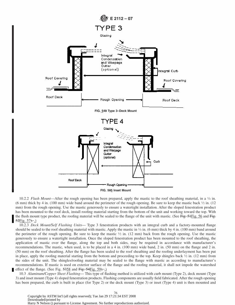
10.2.2 Flush Mount—After the rough opening has been prepared, apply the mastic to the roof sheathing material, in a 1⁄4 in.(6 mm) thick by 4 in. (100 mm) wide band around the perimeter of the rough opening. Be sure to keep the mastic back 1⁄2 in. (12mm) from the rough opening. Use the mastic generously to ensure a watertight installation. After the sloped fenestration producthas been mounted to the roof deck, install roofing material starting from the bottom of the unit and working toward the top. Withthe flush mount type product, the roofing material will be sealed to the flange of the unit with mastic. (See Fig. 51Fig. 56 and Fig.52Fig. 57). .)
10.2.3 Deck Mount/Self Flashing Units— Type 3 fenestration products with an integral curb and a factory-mounted flangeshould be sealed to the roof sheathing material with mastic. Apply the mastic in 1⁄4 in. (6 mm) thick by 4 in. (100 mm) band aroundthe perimeter of the rough opening. Be sure to keep the mastic 1⁄2 in. (12 mm) back from the rough opening. Use the masticgenerously to ensure a watertight installation. Once the sloped fenestration product has been mounted to the roof sheathing, theapplication of mastic over the flange, along the top and both sides, may be required in accordance with manufacturer’srecommendations. The mastic, when used, is to be placed in a 4 in. (100 mm) wide band, 2 in. (50 mm) on the flange and 2 in.(50 mm) on the roof sheathing. After the flange has been sealed to the roof sheathing and the roofing underlayment has been putin place, apply the roofing material starting from the bottom and proceeding to the top. Keep shingles back 1⁄2 in. (12 mm) fromthe sides of the unit. The shingles/roofing material may be sealed to the flange with mastic as according to manufacturer’srecommendations. If mastic is used on exterior surface of the flange and the roofing material, it shall not impede the watershedeffect of the flange. (See Fig. 5358 and Fig. 54Fig. 59). .)
10.3 Aluminum/Copper Sheet Flashing— This type of flashing method is utilized with curb mount (Type 2), deck mount (Type3) and inset mount (Type 4) sloped fenestration products. Flashing components are usually field fabricated. After the rough openinghas been prepared, the curb is built in place (for Type 2) or the deck mount (Type 3) or inset (Type 4) unit is then mounted and
FIG. 549 Type 3–Deck Mount
FIG. 505 Inset Mount
E 2112 – 07
76Copyright by ASTM Int'l (all rights reserved); Tue Jan 29 17:21:34 EST 2008Downloaded/printed byHarry N Nelson () pursuant to License Agreement. No further reproductions authorized.

secured over the rough opening. For deck mount/self flashing units, the application of mastic over the flange may be required inaccordance with manufacturer’s installation instructions. Roofing felt should be extended up the curb or unit frame on all foursides. This will protect the rough opening from possible water penetration from intrusion of water under the roofing material.
10.3.1 Next, bring roofing material up to the bottom of the curb or unit frame. Fabricate the sill-flashing piece. The sill-flashingpiece is to be installed on top on the roofing material in order to insure watershed effect. Corners of sill flashing should bewatertight joints by using mastic, welding or soldering of over lapping pieces. All pieces are to be fastened to the curb or roofsheathing, or both.
10.3.2 After installation of the sill flashing, continuous side flashing pieces are fabricated. These pieces should run the lengthof the curb or unit, over lap the sill-flashing piece and extend 6 in. (150 mm) above the top of the curb or unit. The side flashingpieces should be sealed with mastic to the sill-flashing piece where it overlaps. The sill-flashing piece shall be secured to the roofsheathing/curb/unit frame using acceptable roofing practices. Apply the roofing material up the sides and across the top of the curbor unit. (See Fig. 55). Fig. 60.)
NOTE 829—Roofing material should be sealed to the side flashing pieces with mastic according to manufacturer’s recommendations.
10.3.3 Fabricate the head-flashing piece. The head flashing piece should overlap the side flashing pieces 6 in. (150 mm) andextend above the curb or unit at least 8 in. (200 mm). Corners of the head-flashing piece should be watertight joints by using
FIG. 516 Type 1 with Mastic
FIG. 527 Type 1, Flush Mount, Mastic
FIG. 538 Type 3, Skylight With Mastic
E 2112 – 07
77Copyright by ASTM Int'l (all rights reserved); Tue Jan 29 17:21:34 EST 2008Downloaded/printed byHarry N Nelson () pursuant to License Agreement. No further reproductions authorized.

mastics, welding or soldering of overlapping pieces. Corners that wrap around and overlap the side flashing pieces should be sealedwith mastic. The head flashing piece extending above the curb or unit may be sealed to the roof sheathing with mastic or installedunder the roofing felt to ensure proper watershed effect of intrusion of water underneath the roofing material. Continue with theinstallation of the roofing material.
10.4 Aluminum/Copper Step Flashing (Field-Fabricated or Pre-Engineered)—This method of flashing is utilized with curbmount (Type 2), deck mount (Type 3) and inset (Type 4) sloped fenestration products. (See Figs. 56-Figs. 61-58). 63.)
10.4.1 After the rough opening has been prepared, the curb is built in place or the unit frame is mounted and secured over therough opening. Roofing felt should be extended up the curb or unit frame on all four sides. This will protect the rough openingfrom possible water penetration from intrusion of water under the roofing material.
10.4.2 Bring roofing material up to the bottom of the curb or unit. Install the sill flashing piece, either field fabricated or pre-engineered. The sill flashing piece should be installed on top on the roofing material in order to ensure watershed effect. Corners
FIG. 549 Type 3, Integral Curb, Mastic
FIG. 55 60 Skylights with Sheet Flashing
FIG. 5 61 Skylight with Sheet Flashing (Typical for Types 2, 3 and 4)
E 2112 – 07
78Copyright by ASTM Int'l (all rights reserved); Tue Jan 29 17:21:34 EST 2008Downloaded/printed byHarry N Nelson () pursuant to License Agreement. No further reproductions authorized.

of the fabricated sill-flashing piece should be watertight joints by using mastics, welding or soldering of overlapping pieces. Cornerpieces that extend up the side frame of the curb or unit frame are to be installed in such fashion to interweave with continuingcourses of roofing material and step flashing pieces. All pieces to be fastened to the curb or frame or roof sheathing, or acombination thereof, utilizing acceptable roofing practices or per manufacturers recommendations.
10.4.3 After installation of the sill-flashing piece, continue up both sides of the curb or unit frame, interweaving the step flashingpieces with the roofing material. Align the individual step-flashing piece with the shingle in accordance with acceptable roofingpractices. Step flashing pieces to be fastened to the roof sheathing or unit frame, or both, or curb according to manufacturer’srecommendation or in accordance with acceptable roofing practices.
10.4.4 Field-fabricate or install the pre-engineered head-flashing piece. The head-flashing piece should overlap the side flashingpieces a minimum of 6 in. (150 mm) and extend above the curb or unit at least 8 in. (200 mm). Corners of the fabricatedhead-flashing piece should be watertight joints by using mastics, welding or soldering of overlapping pieces. The head flashingsection is to be installed in such a fashion so as to interweave with continuing courses of roofing material. The head-flashing sectionshould be installed under the roofing felt to ensure watershed effect of intrusion of water underneath roofing material. Allhead-flashing pieces to be fastened to the curb or roof sheathing utilizing acceptable roofing practices or according tomanufacturers recommendations.
10.5 Membrane Flashing—This method of flashing can be used with all four types of sloped fenestration products—Type 1Flush Mount, Type 2 Curb Mount, Type 3 Deck Mount and Type 4 Inset.
10.5.1 Follow the flashing procedures for using mastic for Type 1 and Type 3 fenestration products, substituting a membranetape for the mastic bed in methods shown in 10.2.2 and 10.2.3. See Fig. 59Fig. 64. It may also be recommended to extend themembrane material up the side of the curb or unit frame.
11. Post Installation Procedures
11.1 The installer shall ensure that the fenestration product frame and sash are installed square, plumb and level within thespecified tolerances.
11.2 If necessary to check all aspects of the installation, the installer shall remove all removable sash and screens. Any removeditems shall be remounted or otherwise reinstalled by the installer prior to project completion.
FIG. 57 62 Skylight With Step Flashing (Typical for Types 2, 3 and 4)
FIG. 58 63 Skylight with Step Sheet Flashing (Typical for Types 2, 3 and 4)
E 2112 – 07
79Copyright by ASTM Int'l (all rights reserved); Tue Jan 29 17:21:34 EST 2008Downloaded/printed byHarry N Nelson () pursuant to License Agreement. No further reproductions authorized.

11.3 Check of Operable Elements—The installer shall ensure that all sash move freely within their frames and that weatherstripping or compressible seals make full contact with mating surfaces.
11.3.1 The installer shall ensure that operable hardware such as locks, cranks, latches and hinges, operate smoothly and that alllocking mechanisms engage properly.
11.3.2 The installer shall ensure that all operable elements move freely and function correctly by operating the operableelements of the fenestration product and its hardware.
11.3.3 The installer shall ensure that all accessories and other components of the fenestration product assembly are present, suchas screens and hardware.
11.3.4 Drainage holes shall be inspected for blockage and freed of any obstructions to allow drainage.11.4 Post Installation Surface Care— Exercise caution to avoid damage to fenestration products before and after installation.
Many field-applied protective coatings can damage fenestration sealants, especially insulating glass sealants. Contact manufacturerbefore applying any such coatings. Brick wash (muriatic acid), which is commonly used to clean masonry, can etch glass andcorrode hardware. Exterior surfaces of windows, doors and skylights should be poly-wrapped during masonry acid cleaning.Masking tapes may, when heated by sunlight, bake onto glass and frame surfaces, causing damage when they are removed. Stuccoleft to cure on frames and glass may scratch these surfaces when being removed. Glass and frame surfaces and hardware exposedto leaching water from new concrete or stucco shall be rinsed immediately with clear water to prevent permanent staining. See5.10—Materials Protection.
11.4.1 Weather stripping, hardware components, tracks or vinyl components shall not be painted or stained.11.4.2 Any chemicals, petroleum-based releasing agents or protective coatings made of petroleum or corrosive materials that
are used in the installation of interior finishes or exterior cementitious products such as stucco or EIFS, shall not be applied to anyportion of the fenestration product. These chemicals, agents and coatings could artificially age and deteriorate sealants, framingor other fenestration components.
11.5 Field Tests:11.5.1 Building projects sometimes require testing of installed fenestration products either as a quality assurance procedure or
as proof of compliance with project specifications. The test procedures used for field tests of air leakage and water penetration aredefined in Test Methods E 783 and E 1105 respectively. AAMA 502-90 incorporates these test procedures, describes specimenselection and addresses methods for testing the product alone or the product including installation. The installer shall be familiarwith these procedures and coordinate with and provide assistance to the general contractor when field testing of fenestrationproducts is specified.
11.5.2 At the completion of installation and following all post installation checks and testing, the installer shall deliver to theowner or owner’s agent any and all materials related to the fenestration product. These materials include, but are not limited to:keys; extra hardware accessories; warranty materials; owner’s guides; care and treatment specifications; and other relatedmaterials. (See Test Methods E 283, E 331, and E 547).
12. Keywords
12.1 barrier system; continuity of weather barrier; door anchorage, window; door flashing, window; door installation; doorperimeter sealing; membrane drainage wall system, window; skylight installation; weather resistance; weather-resistantweather-resistive barrier; window installation
FIG. 59 64 Skylight With Membrane Roofing (Typical for Types 2, 3 and 4)
E 2112 – 07
80Copyright by ASTM Int'l (all rights reserved); Tue Jan 29 17:21:34 EST 2008Downloaded/printed byHarry N Nelson () pursuant to License Agreement. No further reproductions authorized.

ANNEXES
(Mandatory Information)
A1.AIR BARRIER FOAM SEALANT USED IN THE ROUGH OPENING GAP (ONE-COMPONENT LOW EXPANSION FOAMSEALANTS) A1. LOW PRESSURE AEROSOL FOAM SEALANTS AND PRE-COMPRESSED FOAM TAPES USED FOR AIR
CONTROLIN THE ROUGH OPENING GAP
Type A Material = Aerosol Foam SealantsType B Material = Pre-Compressed Cellular Tapes
A1.1 Low expansion foam sealants are used to insulate and air seal the rough opening gap. When using foam sealants, theinstaller should consider the following factors prior to installation:
A1.1.1Choose a minimally expanding foam.A1.1.2A rough opening gap of at least 3⁄8 in. width.A1.1.3Select a foam that provides an air tight seal of the gap.A1.1.4The foam applicator should be controllable in terms of foam volume and foaming rate.A1.1.5The gap should not be filled more than one-third full per bead pass.A1.1.6An installed foam fill should not distort the fenestration frame more than 1⁄16 in. (1.5 mm) along any side.
(Warning—Before any material is used to fill the rough opening gap, test the window for ease of operation and cut off the excessportions of the shims.) A1.1 Definitions:
A1.1.1 sealant, aerosol foam, n, in building construction, a foamed compound that is dispensed under pressure from a container.A1.1.2 cellular pre-compressed (open cell) impregnated tapes, n, in building construction, a material supplied pre-compressed
that expands in a joint to its original volume to form a seal.
NOTE A1.1—The air seal material is typically supplied in stick and roll form. The foam may be available from the manufacturer with or without apressure sensitive adhesive surface on one side.
A1.2 Minimally expanding, refers to the volumetric expansion properties of the foam immediately upon its application andduring its curing time.
A1.3 Controllable, refers to the installer’s ability to direct foam at a controlled rate and volume with the use of the applicatorprescribed by the foam manufacturer. Generally, it is desirable that the foam sealant be dispensed through a professional-grade gunor wand, although some straw foam products also offer limited control. (See Figs. A1.1-A1.3A1.2 Low Pressure foam sealants(Type A) and Low Pressure pre-compressed cellular (Type B) tapes are used to insulate and reduce air leakage through the roughopening gap. When using these seals and sealants, the installer should consider the following factors prior to installation:
A1.2.1 “Low Pressure” refers to type A and B material and is the force exerted by the material on the fenestration frame duringits curing time and or recovery time.
A1.2.2 Choose a low-pressure aerosol foam sealant or low pressure pre-compressed foam tape.A1.2.3 Select a material that provides an airtight seal of the gap.A1.2.4 The foam applicator for aerosol foam sealant should be controllable in terms of foam volume and foaming rate (see Figs.
A1.1 and A1.2).A1.2.5 The gap should not be over filled.A1.2.6 A suitable installed foam (Type A or B) fill should not distort the fenestration frame more than 1⁄16 in. (1.5 mm) along
any side. Before any material is used to fill the rough opening gap, test the window for ease of operation and cut off the excessportions of the shims.
A1.4 Fenestration Product Applications:
A1.4.1Follow the fenestration manufacturer’s installation instructions taking special care with shimming and squaring of thefixtures. Trim and caulk around shims before foaming. In cases where no nailing flange is used, apply caulking at the exterior shimlocation before capping or installing exterior wall cladding material. Foam tightly up to the shims to link with caulking.
A1.4.2Before and after foaming, and at all stages of the installation, check to ensure the fenestration product operates properly.Do not foam or continue foaming unless the window or door easily opens and closes. The window or door shall be closed duringfoaming.
A1.4.3Prior to applying the foam, dispense several beads onto drop cloth or newspaper to become familiar with the volume andrate of the foam. Allowing the bead to cure will indicate to the installer how much expansion to expect.
A1.4.4The rough opening gap should be at least 3⁄8 in. (10 mm) wide to facilitate the barrel of the foam applicator. Smaller gapslimit control of the foam applicator, promote overfilling the gap, and increase risk of distortion greater than 1⁄16 in. (1.5 mm). Gaps
E 2112 – 07
81Copyright by ASTM Int'l (all rights reserved); Tue Jan 29 17:21:34 EST 2008Downloaded/printed byHarry N Nelson () pursuant to License Agreement. No further reproductions authorized.

smaller than 3⁄8 in. (10 mm) should be sealed only at the interior face of the gap with a minimal size bead. (See A1.3 FenestrationProduct Applications :
A1.3.1 Follow the fenestration manufacturers installation instructions taking special care with shimming and squaring of thefixtures. Trim and caulk around shims before foaming. In cases where no nailing flange is used, apply caulking at the exterior shimlocation before capping or installing exterior wall cladding material. Foam or apply pre-compressed tape tightly up to the shims
FIG. A1.1 Application of Aerosol Foam Sealant (Type A Material) In Cavity Between Window Frame and Rough Opening
FIG. A1.2 Straw Applicator Type A Material
E 2112 – 07
82Copyright by ASTM Int'l (all rights reserved); Tue Jan 29 17:21:34 EST 2008Downloaded/printed byHarry N Nelson () pursuant to License Agreement. No further reproductions authorized.

to link with caulking. (Note: Consult the fenestration product manufacturer’s recommendation for filling the rough opening gapprior to application.) (Warning—Compatibility with adjacent materials shall be verified by the manufacturers of the foam or tape.)
A1.3.2 Before and after tape installation or foam application, and at all stages of the installation, check to ensure the fenestrationproduct operates properly. Do not foam or continue foam application/installing pre-compressed tape unless the window or dooreasily opens and closes. The window or door shall be closed during installation of Type A or B materials.
A1.3.3 If not familiar with a product then prior to applying the foam, dispense several beads onto drop cloth or newspaper tobecome familiar with the volume and flow rate of the foam. Allowing the bead to cure will indicate to the installer how muchexpansion to expect. Material Type B should be unwound and a small piece cut off to familiarize the user with the direction oftape recovery.
A1.3.4 The rough opening gap should be at least wide enough to permit insertion of the barrel of the foam applicator for TypeA material. Gaps smaller than that recommended by the foam manufacturer should be sealed only at the interior face of the gapwith a minimal size bead.
A1.3.5 Foam between the new frame and the old frame in a replacement window application (see Fig. A1.3).A1.3.6 If the rough opening gap is overfilled, preventing the installation of trim members, the foam must be trimmed to remove
the excess. Type A material must be manually removed using a sharp knife after it cures.A1.3.7 If the rough opening gap is over 2 in. (50 mm) deep, the installer may decide to inject a second optional bead of Type
A foam around the entire fenestration product perimeter creating an air sandwich (see Note A1.2). The first bead is allowed tobecome tack-free (at least 10 minutes) before the second bead is applied. On some fenestration products, one bead is applied fromthe outside and another from the inside. If windows are flanged, both beads are applied from the inside leaving an air gap betweenthem (see Fig. A1.4).
A1.4.5If the rough opening is framed, foam between the frame and the rough opening, if accessible. This also applies if installinga replacement window within the old frame. (See
A1.3.8 Type B material is supplied in various widths to accommodate rough opening depths that exceed 2 inches. Someconfigurations of Type B materials require the material to be adhered on the perimeter of the window frame. Application of thesepre-compressed tapes to the fenestration frame shall be placed flush to the back of the nailing flange prior to mounting the windowin the rough opening (see Figs. A1.6-A1.8). A 7⁄32 in. (5.5 mm) clearance between the fenestration frame and the wall framing oneach side of the rough opening is required when using type B materials. The installer should follow the installation instructionsfrom the sealant manufacturer for proper operation of these Type B materials. A second run of tape can be installed if jambextensions are utilized. The second pass can be applied after the jamb extensions are applied from the inside leaving an air gapbetween the Type B materials (see Fig. A1.9). Type B material can be cut and recessed into the shim space using a putty knife orbox cutter (see Fig. A1.10). Type B material can be covered with an interior trim piece immediately after installation.
A1.4 Precautions:
A1.4.1 DO NOT OVERFILL THE CAVITY. With Type A material, allow for foam expansion during cure.A1.4.2 If foam or tape is used between pan flashing and the window or door, the exterior foam bead/tape shall not distort the
pan or obstruct proper drainage.
FIG. A1.3 Locations for Type A Material with Replacement Window
E 2112 – 07
83Copyright by ASTM Int'l (all rights reserved); Tue Jan 29 17:21:34 EST 2008Downloaded/printed byHarry N Nelson () pursuant to License Agreement. No further reproductions authorized.

A1.4.3 Wait until foam has cured when using Type A material (consult manufacturer’s recommendation) before cutting excessfoam flush with wall and installing trim (see Fig. A1.5).
A1.4.6If the rough opening gap is overfilled, the foam must be manually removed after it cures, and the proper amount of foamshould be re-applied.
A1.4.7If the rough opening gap is over 2 in. (50 mm) deep, the installer may decide to inject a second optional bead of foamaround the entire fenestration product perimeter creating an air sandwich. The first bead is allowed to become tack-free (at least10 minutes) before the second bead is applied. On some fenestration products, one bead is applied from the outside and anotherfrom the inside. If windows are flanged, both beads are applied from the inside leaving an air gap between them. (See Fig. A1.6and Fig. A1.7).
A1.4.8DO NOT OVERFILL THE CAVITY. Fill gaps only one-third full to allow for proper expansion and to minimize the riskof distorting the fenestration product frame.
A1.4.9If pan flashing is used, the exterior foam bead shall not make direct contact with the pan to ensure proper drainage.A1.4.10Wait until foam has cured (consult manufacturer’s recommendation) before cutting excess foam flush with wall and
installing trim. Check operation of window or door one final time. ). Check operation of window or door one final time.(Warning—Foam cleaners or solvents may not be compatible with all fenestration materials. Consult the fenestrationmanufacturers’ recommendations before using cleaners on fenestration products.)
A1.4.4 At the head rough opening gap, the installer should apply a single bead of foam sealant just sufficient to air-seal this area.This technique reduces the downward force transmitted to the head jamb of the window should the structural header tend to sagover time.
NOTEA1.1—At the head rough opening gap, the installer should apply a single bead of foam sealant just sufficient to air-seal this area. This techniquereduces the downward force transmitted to the head jamb of the window should the structural header tend to sag over time. A1.2—Consult thefenestration product manufacturer’s recommendation for filling the rough opening gap prior to application.
NOTE—IG. A1.6 Installus Type B materials around the head and jamb conditions flush to the backside of O finned units. For access reasons, some typeB materioal must be instal Slecd prior to the fenestration prod Buct being fastened A in the rough oppening. First remove the releacse liner from thepre-compressed tape.
FIG. A1.6 Type B Material Release Liner Removed from Tape
E 2112 – 07
84Copyright by ASTM Int'l (all rights reserved); Tue Jan 29 17:21:34 EST 2008Downloaded/printed byHarry N Nelson () pursuant to License Agreement. No further reproductions authorized.

NOTEA1.2—Consult the fenestration product manufacturer’s recommendation for filling the rough opening gap prior to application. A1.3—For accessreasons, some type B material must be installed prior to the fenestration product being fastened in the rough opening.
NOTE—A1.7 Ipplly the tape with the pressure sensitrive atdhesive side adhered ton o the f Foramie of the fengestra Vtionyl W product; keep the tapecontinuous around frame cowrners.
FIG. A1.7 Type B Material Applied to Window Frame
E 2112 – 07
85Copyright by ASTM Int'l (all rights reserved); Tue Jan 29 17:21:34 EST 2008Downloaded/printed byHarry N Nelson () pursuant to License Agreement. No further reproductions authorized.

FIG. A1.4 Optional Second Bead Approach for Type A Material
FIG. A1.5 Excess Type A Material Trimmed with a Sharp Knife
E 2112 – 07
86Copyright by ASTM Int'l (all rights reserved); Tue Jan 29 17:21:34 EST 2008Downloaded/printed byHarry N Nelson () pursuant to License Agreement. No further reproductions authorized.

NOTE—FIG. A3.1 Dold the poly to the intermior side of the fenestrationg In product. Pull the poly release after the fenestration pr Loduct has beenfastened in the roug Hh opening to fill the rough opening gap with the pre-compressed tape.
FIG. A1.8 Type B Material Applied with Polyethelene Liner
NOTE—IG. A3.2 Pnstallation F of an optional second pass of tape can be installed to the interior side of the rough opening gap between the jambextension and the stud.
FIG. A1.9 Type B Material Applied After Fenestration Frame
E 2112 – 07
87Copyright by ASTM Int'l (all rights reserved); Tue Jan 29 17:21:34 EST 2008Downloaded/printed byHarry N Nelson () pursuant to License Agreement. No further reproductions authorized.

A2. EMERGENCY ESCAPE AND RESCUE REQUIREMENTS
A2.1 Windows shall meet applicable egress code requirements.
A2.2 Installing windows, especially when the existing window frame is left in place, can significantly reduce the size of theclear opening by as much as 2 in. (50 mm) of height and 3 in. (75 mm) of width. This may prevent emergency egress.
A2.3 Jurisdictions have specific egress requirements for windows. Know what the local building official requires beforereplacing an egress window.
A3. MINIMUM HEIGHT REQUIREMENTS FOR INTERIOR REAR LEG HEIGHT OF PAN FLASHING
A3.1 Determining Interior Leg Heights—Table A3.1 is meant to be a guide to the installer. The pan flashing height representsthe known rise of a vertical column of water with an unsealed pressure differential plus 1⁄8 in. (3 mm) at different pressures. fora frame-levelling allowance. However, several factors may affect performance, and the flashing requirements may vary. (See Figs.A3.1-A3.4 and Fig. A3.2). .)
NOTE—Some Types of S B materials are pre-compressed to 3/16 in. t Jo fit into minimal gaps between the window frame and the wall.FIG. A1.10 Type B Material to Fit Small Gaps
TABLE A3.1 Pan Height
WTP D.P. H1
Water Test PressureP.S.F. (Pa)
Design PressureP.S.F. (Pa)
WaterHeightand
Minimum Leg Height,in. (mm)
Water Test PressureP.S.F. (Pa)
D.P.Design Pressure
P.S.F. (Pa)
H1Water Height and
Minimum Leg Height,in. (mm)
2.86 (140) 15 (720) 11⁄16 in. (18 mm)3.0 (150) 20 (960) 3⁄4 in. (19 mm)3.75 (180) 25 (1200) 7⁄8 in. (21 mm)4.5 (220) 30 (1440) 1 in. (25 mm)5.25 (260) 35 (1630) 1-1⁄8 in. (31 mm)6.0 (290) 40 (1920) 1-5⁄16 in. (34 mm)6.75 (330) 45 (2160) 1-7⁄16 in. (37 mm)7.5 (360) 50 (2400) 1-5⁄8 in. (41 mm)8.25 (400) 55 (2640) 1-3⁄4 in. (45 mm)9.0 (440) 60 (2880) 1-7⁄8 in. (48 mm)9.75 (470) 65 (3120) 2 in. (50 mm)
E 2112 – 07
88Copyright by ASTM Int'l (all rights reserved); Tue Jan 29 17:21:34 EST 2008Downloaded/printed byHarry N Nelson () pursuant to License Agreement. No further reproductions authorized.

Example: A DP-20 (assuming no coefficients) is rated for 20 psf (960 Pa). The required panning height, at 0.192 q, would be3.84 in. + 1⁄8 in. (98 mm + 3 mm), or about 4 in. (100 mm). Practically, this is not usually needed because of weather historyindicating that high rain and wind are usually not simultaneous, and is why windows are normally tested at 15% of design pressure,which in this example is 3 psf (150 Pa). 3 psf30.192=0.57 in. or about 9⁄16 in. (98 mm + 3 mm), or about 4 in. (100 mm). Windowsare normally tested at 15 % of design pressure, which in this example is 3 psf (150 Pa). 3 psf 3 0.192 = 0.57 in. or about 9⁄16
in. + 1⁄8 in. = 11⁄16 in. (143.6 Pa30.101 = 14.5 mm + 3 mm = 17.5 mm).
FIG. A3.2 Pan Flashing—Surface Barrier System
FIG. A3.3 Pan Flashing—Concealed Barrier System
E 2112 – 07
89Copyright by ASTM Int'l (all rights reserved); Tue Jan 29 17:21:34 EST 2008Downloaded/printed byHarry N Nelson () pursuant to License Agreement. No further reproductions authorized.

in. (143.6 Pa 3 0.101 = 14.5 mm + 3 mm = 17.5 mm).A3.1.1 The designer of pan flashing should consider not only the anticipated level of contained water in the pan flashing during
a maximum weather event but the sealing of all penetrations and joints. All joints should be located if possible so that they willnot be exposed to standing water or heavy water concentrations. This can be accomplished by turning up sections of the materialfrom which the flashing is made at the back and ends of the pan flashing as illustrated in Fig. A3.2. Where sealants are used to
FIG. A3.4 Configurations of Typical Sill Pan Flashing—Isometric
FIG. A3.1 Determining Rear Leg Heights
E 2112 – 07
90Copyright by ASTM Int'l (all rights reserved); Tue Jan 29 17:21:34 EST 2008Downloaded/printed byHarry N Nelson () pursuant to License Agreement. No further reproductions authorized.

seal the joints they should be located away from the bottom horizontal surface of the pan flashing. When designing the pan flashingthe designer should provide anchor locations which are above the highest level of expected water accumulation and the lowest edgeof the various water barriers provided. For example, if the rear upturned leg is to be 1 in. (25 mm) above the bottom of the flashingand the end dams are to be used for anchoring the pan flashing, then the end dams should be designed to extend sufficiently above1 in. (25 mm) to allow the fasteners to be located above the top of the rear leg. This might require that the end dams extend asmuch as 3 in. (75 mm) above the bottom surface of the flashing and the anchor fasteners are located at least 2 in. (50 mm) abovethe bottom of the flashing. Designing the pan flashing so that joints, sealants and fasteners are always above the highest expectedwater level prevents the sealants and penetrations from being exposed to standing water and increases the likelihood of long termperformance of the pan flashing.
NOTE A3.1—Rear leg pan heights can be reduced by the use of continuous air infiltration seals or engineered sealant joints.
A4. SEALANTS
A4.1 The following tables are provided to aid in sealant selection. This information should be used only as a general guidelineto narrow down the number of sealants that may be suitable for a given use and substrate materials.
A4.2 Uses and applicable specifications are given in Table A4.1. It should be recognized by the purchaser or design professionalthat not all sealants meeting a listed specification are suitable for the intended use. Commercially available products meeting alisted specification vary considerably in performance characteristics. Suitability of a specific product should be verified with thesealant supplier following the guidelines in 5.10.1.
A4.3 Table A4.2 provides general adhesion characteristics for the most commonly used types of sealants. A wide variety ofmaterials exists within most of the listed substrate categories, and commercially available sealant products within any one sealanttype can vary considerably in adhesion to a given material. A range is provided where a significant variation in adhesion betweenproducts can be expected. For further information see Terminology C 717. (See AAMA 800).
E 2112 – 07
91Copyright by ASTM Int'l (all rights reserved); Tue Jan 29 17:21:34 EST 2008Downloaded/printed byHarry N Nelson () pursuant to License Agreement. No further reproductions authorized.

APPENDIXES
(Nonmandatory Information)
X1. WINDOW/DOOR FLASHING TYPES
INTRODUCTION
The following describes the various types of common window and door flashing products availableon the market.
TABLE A4.1 Applicable Specifications
NOTE 1—Where more than one specification is listed for an application, the sealant is required to meet at least one of the specifications.NOTE 2—X = Applicable Specification.
UsePerimeter Joints Total
Cyclic Movement Bedding of Fin,Flashing, Etc
Thresholds SillsEnd DamsPanning
Specification >15 % <15 %
Specification C 834 Emulsion (Latex) X and AAMA 808Specification C 920 Elastomeric X X and AAMA 808 X X X XSpecification C 1085 Butyl Solvent Release X and AAMA 808 X X X XSpecification C 1311 Solvent Release X and AAMA 808 X X X XAAMA 804.3 Butyl Tapes XAAMA 808.3 Ext. Perimeter X with above XAAMA 809.2 Non-Drying X XApplicable Sections 5.10.3.1, 7.2 5.10.3.2, 7.2.3 5.10.6, 8.1.1, 10.2.1 5.10.8 5.10.8.1, 5.10.8.2 5.10.8.2
TABLE A4.2 Sealant Adhesion
NOTE 1—N/A = Not ApplicableN/R = Not RecommendedG = Good = Adhesion of 5 PLI and 75 % cohesive failure minimum as measured by Test Method C 794F = Fair = Adhesion of 5 PLI and less than 75 % cohesive failure as measured by Test Method C 794P = Poor = Adhesion less than 5 PLI and predominantly adhesive failure
Sealant Type Silicone Latex Polyurethane Solvent Release Butyl Tape Notes About Substrates
Specification C 920 C 920 C 834 C 920 C 1085 C 1311AAMA
809AAMA
804
Aluminum Mill Finish G G F G G P-G G GAluminum Anodized G G F G G P-G G GBuilding Paper (Asphalt) P-G P-G P-G P-G P-G P-G G G Compatibility with solvent release sealants shall be verifiedBrick G G F G G P-G NA NAConcrete F-G F-G P-F G G P-G G P Adhesion in areas of prolonged moisture exposure shall be verifiedCopper P-G P-G P-F F-G G P-G G G Some sealants can produce corrosionEIFS F-G F-G P-F F-G NR NR NA NA Test Method C 1382 is used to determine adhesion to finish or base
coatsSteel Galvanized P-G P-G P-F P-G G P-G G G
Glass G G F P-G F P-G NA G Test Method C 794 after ultraviolet exposure is used to determineadhesion
Painted Surfaces P-G P-G P-G P-G P-G P-G G P-G Adhesion of a specific sealant product and job site coating(s) shouldbe verified
Polyethylene P P P P-G P-G P-F G GStone G G F G G F-G G P-F Resistance to vehicle migration and staining should be verifiedStucco G G F G F-G F-G NA NAVinyl P-G P-F P-F P-G P-G P-G G P-G Cleaning by Isopropyl Alcohol wipe is recommendedWood Raw G G F-G G F-G P-G G P-GWood Treated G G F-G G F-G P-G G P-G
E 2112 – 07
92Copyright by ASTM Int'l (all rights reserved); Tue Jan 29 17:21:34 EST 2008Downloaded/printed byHarry N Nelson () pursuant to License Agreement. No further reproductions authorized.

X1.1 Flexible Flashings Flexible Flashings—Mechanically Fastened
X1.1.1 Paper Flashing— Typically two sheets of kraft paper laminated with asphalt and reinforced with fiberglass yarns. Theseproducts shall meet Test Method D 779, with a water resistance of at least 24 + h.
X1.1.2 Polyethylene Coated Flashing —These products have a polyethylene coated exterior. There are two qualities: one withpolyethylene coating on both sides, with polyethylene coating on one side with kraft paper on the other side. Both of these typesare reinforced with fiberglass yarns. These products shall meet Test Method D 779, and those with two-sided coating shall havea water resistance of at least 48 + h.
X1.1.3 Bitumen Flashing—The flashing has a bitumen type filler between two sheets of polyethylene and/or polypropylene.
NOTE X1.1—Consensus material standards currently do not exist for some materials that may be used as flexible perimeter flashing. Consequently,these materials are not included in this version of E 2112 as recommended flashing materials. This does not mean that these materials should never be
FIG. A4.1 Types of Sealant Joints
E 2112 – 07
93Copyright by ASTM Int'l (all rights reserved); Tue Jan 29 17:21:34 EST 2008Downloaded/printed byHarry N Nelson () pursuant to License Agreement. No further reproductions authorized.

used but that if they are specified and used the burden of determining compatibility, adhesion, suitability and long term performance is the responsibilityof the specifier. The specifier is cautioned to carefully investigate the applicability of all flashing materials. Since some materials may adhere to someframing and sheathing materials and not others, durability of materials may be affected by temperature and the cleanliness of building surfaces andmaterials, and some flashing materials may not be compatible with all gunnable sealants required in the designed flashing detail, the specifier shouldinvestigate suitability by testing the desired detail and materials using project materials and environmental conditions. This may involve mock-up testing,accelerated exposure testing and consultation with the suppliers of all contemplated materials. Some materials such as asphalt paper flashing can bespecified by simply specifying the requirements of materials standards such as Test Method D 779. Materials standards for other flashing materials areunder development and will be incorporated into this standard when approved.
X1.2 Flexibile Flashing—Adhesive Type Flexible Flashing—Self-Adhesive Type
X1.2.1 Polyethylene Flashing with Adhesive Strip—These products are coated (see X1.1.2). They are laminated and reinforced.The product has a 3-in. adhesive strip designed to cover the window flange to provide additional sealing between the flange andeither the flashing under the flange or the frame, or both, depending on which installation method is used to install the fenestrationproduct. This type of flashing is used as a system in conjunction with other types of flashing. These typically are one of thematerials described in X1.1.2.
X1.2.2 Bitumen Type Flashing—Bitumen flashing typically has a rubberized bitumen material applied to a sheet ofpolyethylene, polypropylene, or in some cases a foil. In the majority of these products, the release sheet is pulled off, exposingthe rubberized bitumen adhesive, which is then put down on the flange or the frame, depending on the installation method beingused. These products provide a complete seal, as their adhesive is across the entire product. —Bitumen flashing typically has arubberized bitumen material applied to a sheet of polyethylene, polypropylene, or in some cases a foil. In the majority of theseproducts, the release sheet is pulled off, exposing the rubberized bitumen adhesive, which is then put down on the flange or theframe, depending on the installation method being used.
X1.2.3 Butyl Type Flashing—Butyl flashing typically has a butyl adhesive applied to a sheet of polyethylene, polypropylene,rubber, woven cloth, non-woven cloth, foil, or in some cases a combination of these sheets. In the majority of these products, therelease sheet is pulled off, exposing the butyl adhesive, which is then put down on the flange or the frame, depending on theinstallation method being used.
X1.2.4 Some elastomeric type flashings are formable so they can cover 3-dimensional and non-linear shapes such as the headsof round top windows. Some other types of flashings have less than 100 % adhesive coverage integrated in the film or carrier thatcan be used in sill applications covering the bottom flange.
X1.3 Rigid Flashing
X1.3.1Rigid flashings are generally of metal, most commonly either galvanized or copper. These products are often custom madein order to fit a particular window or door, or both.
X1.41994 Uniform Building Code—Flashing Requirements
X1.4.1Refer to UBC 14.104.2, Grade A, High Water-Vapor Resistant. Grade A paper shall have the dry tensile strength,water-resistance and water-vapor transmission properties shown in Table 14-1-A.
X1.4.2Refer to UBC 14.104.3, Grade B, Moderate Water-Vapor Resistant. Grade B paper shall have the dry tensile strength,water-resistance and water-vapor transmission properties shown in Table 14-1-A.
X1.4.3Refer to UBC 14.104.4, Grade C, Water Resistant. Grade C paper shall have the dry tensile strength and water-resistanceproperties shown in Table 14-1-A.
X1.4.4Refer to UBC 14.104.5, Grade D, Water-Vapor Permeable. Grade D paper shall have the dry tensile strength,water-resistance and water-vapor transmission properties shown in Table 14-1-A.
X1.4.5Refer to UBC 14.104.6, Style 1a, Uncreped, Unreinforced. Style 1a paper shall be uncreped and shall not be reinforced.X1.4.6Refer to UBC 14.104.7, Style 1b, Uncreped, Unreinforced, Red Rosin Sized. Style 1b paper shall be uncreped, not
reinforced, and shall be coated with red rosin sizing.X1.4.7Refer to UBC 14.104.8, Style 2, Uncreped, Unreinforced, Saturated. Style 2 paper shall be uncreped, not reinforced, and
shall be saturated or infused with asphalt on both sides. Ground wood pulp may be included in the paper.X1.4.8Refer to UBC 14.104.9Style 3, Creped One Direction, Unreinforced. Style 3 paper shall be creped in one direction, not
reinforced, and shall have a minimum elongation (stretch) of 15 percent.X1.4.9Refer to UBC 14.104.10, Style 4, Uncreped, Reinforced. Style 4 paper shall be uncreped and reinforced.X1.3.1 Rigid flashings are generally of metal, most commonly either galvanized or copper. These products are often custom
made in order to fit a particular window or door, or both.
X2. CAUTIONS FOR INSTALLATION
INTRODUCTION
The following list outlines specific cautions and issues of concern for the preparation andinstallation of fenestration products into building openings.
E 2112 – 07
94Copyright by ASTM Int'l (all rights reserved); Tue Jan 29 17:21:34 EST 2008Downloaded/printed byHarry N Nelson () pursuant to License Agreement. No further reproductions authorized.

X2.1 Thermal Break Fenestration Products
X2.1.1 Independent Frame Anchors —Independently anchor the inner and outer metal frame portions of thermally brokenfenestration systems to the building structure, where polyurethane thermal barrier material structurally joins the inner and outermetal frame portions in tension. Do not install anchorage fasteners through the thermal barrier material.
X2.1.2 Weep Hole Location—Inspect weep hole locations prior to installation. Do not drill weep holes through both the metalframe and the thermal barrier material. Do not install products with mislocated weep holes.
X2.1.3 Cracks in Thermal Barrier —Inspect the thermal barrier surface for visible defects prior to installation. Do not installthermally broken fenestration products with hairline or larger cracks, tears or splits in the thermal barrier material.
X2.1.4 Aluminum Subsills—Aluminum subsills should be thermally isolated from the fenestration product sill member andexposed interior surfaces. Independently anchor the subsill and the fenestration product. Do not install aluminum subsills withpolyurethane thermal breaks.
X2.2 Weep Holes and Weepage Path
X2.2.1 Maintain free drainage openings for weep holes and weepage drain paths. Do not block weep holes with insulation.Install insulation so that it does not get wet from weepage at weep holes and weepage paths. Do not seal weep holes or pan flashingdrainage outlets with sealant.
X2.3 Mulled Windows/Doors
X2.3.1 Edges of Flashings and Weather-resistantWeather-Resistive Barriers—Integrate and seal perimeter flashings andweather-resistantweather-resistive barriers (WRB) to be weather tight and lapped shingle-fashion at vertically and horizontallymulled fenestration units. Do not allow the WRB or flashing edges to be unsealed with vertically mulled units placed less than 9in. apart. Do not allow the WRB or flashing edges of horizontally mulled fenestration units to be lapped so that the laps are notcounter-flashed.
X2.4 Curved Window / Door Heads
X2.4.1 Flashing Curved Window/Door Heads—Install a separate head flashing cap at the tops of curved window/door unitswhich do not provide a continuous flashing fin.
X2.5 Wood and Plastic Frame Cracks
X2.5.1 Frame Cracks— Inspect the surface condition of wood and plastic framed units for visible cracks, splits or other defectswhich might interfere with the fastening or flashing of the product in the building opening.
X3. BIBLIOGRAPHY / OTHER REFERENCED INSTALLATION GUIDES
X3.1 Residential Fenestration Product Installation Guide, Version 1.3:
Association of Fenestration Product Installers 11300 U.S. Highway One, No. 400AWDI, LLC (Association of Window and Door Installers),
11300 U.S. Highway One, No. 400,North Palm Beach, FL 33408
X3.2 AAMA 2400 (CAWM 400)—Standard Practice for Installation of Windows with Integral Mounting Flange in WoodFrame Construction
X3.3 AAMA 2410 (CAWM 410)—Standard Practice for Installation of Sliding Glass Doors with Integral Mounting Flange inWood Frame Construction
X3.4 Recommended Procedure for Installation of Vinyl Windows:
Vinyl Fenestration Product Institute Society of the Plastics Industry, Inc.,1275 K Street NW, Suite 400,Washington, DC 20005
X3.5 CSA A440.4—Fenestration Product Installation:
Canadian Standards Association 178 Rexdale BoulevardCanadian Standards Association,
178 Rexdale Boulevard,Rexdale, Ontario M9W 1R3
X3.6 CEGS Section 08520—Aluminum Window Installation Guide Specification:
Department of the Army,Army Engineer Division,
E 2112 – 07
95Copyright by ASTM Int'l (all rights reserved); Tue Jan 29 17:21:34 EST 2008Downloaded/printed byHarry N Nelson () pursuant to License Agreement. No further reproductions authorized.

Huntsville CEHND-ED-ES (GS Section),P.O. Box 1600,Huntsville, AL 35807-4301
X3.7 ASTM Standards on Lead Hazards Associated with Buildings:
ASTM International, Customer Service,100 Barr Harbor Drive,West Conshohocken PA 19428-2959
X3.8 Product Rating Standards:
ANSI/AAMA/NWWDA 101/I.S.2-97, Voluntary Specifications for Aluminum, Vinyl (PVC) and Wood Windows and GlassDoors
ANSI/ISDI-102-1993, American National Standard for Insulated Steel Door Systems—Installation StandardCSA A440-M90, Windows—A National Standard of CanadaSDI-I22-90, Installation and Troubleshooting Guide for Standard Steel Doors and Frames
X3.9 Reference Workbook:
Nail-on Windows: Installation and Flashing Procedures for Windows & Sliding Glass Doors, 1995, 1st Edition; RobertBateman, DTA, Inc. Mill Valley, CA 94941
X3.10 Product Certification Agencies:
AAMA American Architectural Manufacturers AssociationWDMA Window and Door Manufacturers AssociationNAMI National Accreditation Management InstituteNFRC National Fenestration Rating CouncilCWDMA Canadian Window and Door Manufacturers AssociationITS-WH Intertek Testing Services—Warnock-Hersey
ASTM International takes no position respecting the validity of any patent rights asserted in connection with any item mentionedin this standard. Users of this standard are expressly advised that determination of the validity of any such patent rights, and the riskof infringement of such rights, are entirely their own responsibility.
This standard is subject to revision at any time by the responsible technical committee and must be reviewed every five years andif not revised, either reapproved or withdrawn. Your comments are invited either for revision of this standard or for additional standardsand should be addressed to ASTM International Headquarters. Your comments will receive careful consideration at a meeting of theresponsible technical committee, which you may attend. If you feel that your comments have not received a fair hearing you shouldmake your views known to the ASTM Committee on Standards, at the address shown below.
This standard is copyrighted by ASTM International, 100 Barr Harbor Drive, PO Box C700, West Conshohocken, PA 19428-2959,United States. Individual reprints (single or multiple copies) of this standard may be obtained by contacting ASTM at the aboveaddress or at 610-832-9585 (phone), 610-832-9555 (fax), or [email protected] (e-mail); or through the ASTM website(www.astm.org).
E 2112 – 07
96Copyright by ASTM Int'l (all rights reserved); Tue Jan 29 17:21:34 EST 2008Downloaded/printed byHarry N Nelson () pursuant to License Agreement. No further reproductions authorized.