design the vtol aircraft for land surveying purposes
TRANSCRIPT

DESIGN THE VTOL AIRCRAFT FOR LAND SURVEYING PURPOSES
SHAHDAN BIN AZMAN
A report submitted as the first draft of the final year project in semester 1 2016/2017
Faculty of Mechanical Engineering
Universiti Teknologi Malaysia
March 2017

i
TABLE OF CONTENTS
CHAPTER TITLE PAGE
TABLE OF CONTENTS i
LIST OF TABLES iii
LIST OF FIGURES iv
LIST OF ABBREVIATIONS v
LIST OF SYMBOLS vi
LIST OF APPENDICES ix
INTRODUCTION 1
1.1 Background Research 2
1.1.1 Applications of UAV in land surveying 2
1.2 Problem Statement 2
1.3 Research Objectives 4
1.4 Research Scopes 4
1.5 Schedule Planning 4
LITERATURE REVIEW 7
2.1 RC Aircraft 7
2.2 VTOL Aircraft 9
2.3 Aircraft Design 10
2.3.1 Conceptual Design 11
2.3.2 Preliminary Design 14
2.3.3 Detail Design 16
2.4 Fabrication Method 16

ii
METHODOLOGY 18
3.1 Flow Chart 18
3.2 Conceptual Design 20
3.2.1 Feasibility Study 20
3.2.2 Weight Estimation 21
3.2.3 Preliminary Sizing 22
3.2.4 Airfoil Selection 28
3.2.5 Materials Selection 28
3.2.6 Accessories Selection 30
3.2.7 Preliminary Centre of Gravity and Moment of Inertia
Estimation 30
3.2.8 Aerodynamic Analysis 30
3.2.9 Preliminary Performance Analysis 32
3.3 Optimization 39
3.4 Preliminary Design, Detail Design and Fabrication 40
3.5 Validation Works and Flight Test 40
RESULTS AND DISCUSSIONS 41
CONCLUSION 42
REFERENCES 43

iii
LIST OF TABLES

iv
LIST OF FIGURES

v
LIST OF ABBREVIATIONS
3D Three Dimensional
CAD Computer Aided Design
GIS Geospatial Information System
GPS Global Positioning System
L/D Lift to Drag ratio
LIDAR Light Detection and Ranging
Li-Po Lithium polymer
LLT Lifting Line Theory
RC Radio Controlled
STOL Short Take-Off Landing
UAV Unmanned Aerial Vehicle
UIUC University Illinois Urbana Champaign
USAF DATCOM United State Air Force Data Compendium
VLM Vortex Lattice Method
VTOL Vertical Take-Off Landing
vi
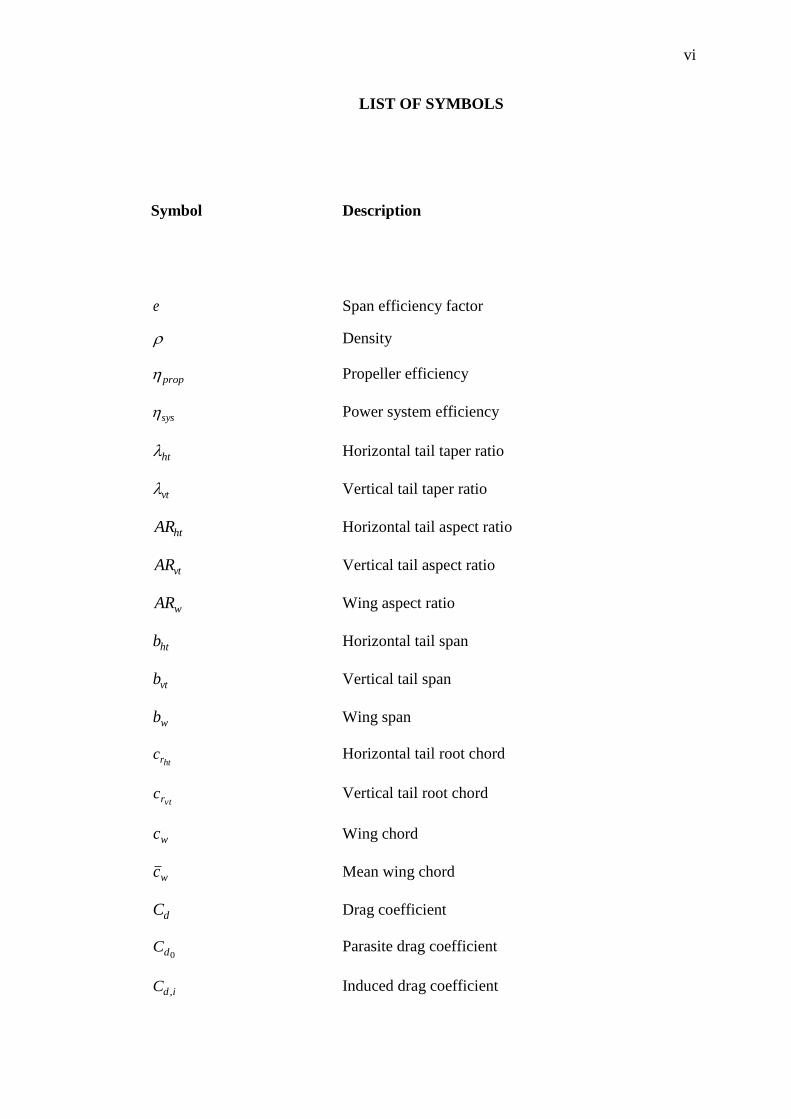
LIST OF SYMBOLS
Symbol Description
e Span efficiency factor
Density
prop Propeller efficiency
sys Power system efficiency
ht Horizontal tail taper ratio
vt Vertical tail taper ratio
htAR Horizontal tail aspect ratio
vtAR Vertical tail aspect ratio
wAR Wing aspect ratio
htb Horizontal tail span
vtb Vertical tail span
wb Wing span
htrc Horizontal tail root chord
vtrc Vertical tail root chord
wc Wing chord
wc Mean wing chord
dC Drag coefficient
0dC Parasite drag coefficient
idC , Induced drag coefficient

vii
LC Lift coefficient
E Endurance
maxE Maximum endurance
subelI Current of subsystem
fuselageL Fuselage length
vtL Vertical tail arm length
htL Horizontal tail arm length
aP Power available
0P Power output
RP Power required
0,RP Power required to overcome parasite drag
iRP , Power required to overcome induced drag
R Range
maxR Maximum range
vtS Vertical tail area
htS Horizontal tail area
wS Wing area
aT Thrust available
0,RT Thrust required to overcome parasite drag
iRT , Thrust required to overcome induced drag
elU Voltage of power supply
vtV Vertical tail volume coefficient
htV Horizontal tail volume coefficient
V Free stream velocity
0W Total gross weight

viii
crewW Crew weight
emptyW Empty weight of the aircraft
fuelW Fuel weight
MTOWW Maximum take-off weight
payloadW Payload weight
elC Electrical capacity of power supply

ix
LIST OF APPENDICES
APPENDIX TITLE PAGE
1
CHAPTER 1
1 INTRODUCTION
Unmanned Aerial Vehicle (UAV) or people easily called it as drone has been
widely known of its benefits in changing the 21st century airspace scenery. Its
application in the early age of their appearance was widely been used for military
purposes especially for deploying mission, reconnaissance and attacking role. At the
early age of the UAV’s introduction, the configurations and augmentation system of
the UAV is complicated and few exposures are given to the civilians about its
applications. One of the advantages of UAV is its capability of survey required data
in less time compared to manned vehicles (Magnotta, 2015). Thus, it gives potential
to bring benefits in both productivity and handling cost.
Into this awareness, recent innovations of UAV has given the possibility to the
civilians to use the UAV for either personal purposes or commercial purposes. One of
the biggest changes in UAV is the size has been scale down which will give access to
the operations in a more confine space. Therefore, some people take this opportunity
to implement the benefits of UAV or popularly been called as drone, into our daily
life such as land surveying, aerial photography, delivery, wildlife research, and news
and etc. Further innovations in these small scale UAV will improve the user
experiences and productivity efficiency. This project will be focused on the design and
modification of an aircraft that will be converted as an UAV for land surveying
purposes.

2
1.1 Background Research
1.1.1 Applications of UAV in land surveying
Surveillance is one of the main objectives in most of UAV creation. Previously,
before UAV was invented, manned vehicles is implemented to carry out the operation
of monitoring the condition of the land activity such as the roadway network, vehicle
movements, land development and etc (Zaryab et. al, 2016). Nevertheless,
implementation of manned vehicle in this operation affect the environmental issues
especially the noise produce from the fuel-powered helicopter and aeroplane. Besides,
cost are way more expensive if compare to latest implementation of UAV in this
activity.
Therefore, UAV have been suggested in most of the land surveying operators
because of its cost effectiveness and safety to the pilot’s life. Besides, UAV especially
the small scale UAV have greater maneuverability and control in a low flight and
confined space. Nevertheless, permission of access in a prohibited flying areas is still
a main consideration in every land surveying operations in order to respect one’s
privacy of their properties.
1.2 Problem Statement
Nowadays, the Geospatial Information System (GIS) operators used small UAV
to conduct the air-based land surveying operations. It is because the capability of UAV
to follow the GPS-guided flight path. Besides, small scale UAV is now capable to be
equipped with advanced equipment such as Light Detection and Ranging (LIDAR)
sensor, thermal imaging camera, high resolution camera and etc. Consequently,
improved flight quality of UAV is obligatory as these equipment carried by UAV are
very expensive and fragile.
3
Some of GIS operators focus on the data collection in a rural areas for future
infrastructure development, scheduled site inspection, illegal forest logging activity
and etc. For example, illegal logging activity is a serious environmental issue that must
to overcome and prevent by the all party. Ability of UAV in offering live streaming
view will help the related forestry authorities to terminate the activity of these illegal
loggers. Therefore, the ability of UAV to fly in rural areas especially in forest is very
important in order for the operators’ mission deployment in such area.
The type of UAV been used is varied which mostly depends on the period of
mission deployment. For example, land surveying that involves data collection of the
topography status of a certain areas might require more than average of one hour flight
time. Longer flight time means better endurance of an UAV must have which
obviously fixed-wing type of UAV has greater benefits in term of endurance.
Therefore, fixed-wing type of UAV is preferable in most GIS since it has better
endurance, range and payload access.
Fixed-wing type especially Short Take-Off Landing (STOL) require some a
specified take-off and landing airspace to make it launch properly. The main problems
face by the operators are the difficulty to launch and land these aircraft safely deploy
the aircraft during mission deployment especially in a confined space such as forest,
crowded city, oil platform and etc. This difficulty will increase the possibility of flight
crash. Besides, the ability of the VTOL aircraft to take-off and land in an flight crash
also occurred due to unexpected conditions such as gust, poor ground system
conditions, and technical faulty are crucialand etc. Therefore, it is very important to
prepare make the aircraft launch and land safely for with a stable mechanism of
vertical take-off and landing for better flight quality during operation and aircraft’s
life cycle.

4
1.3 Research Objectives
There are three objectives to be achieved in this project.
1. Firstly, to design an aircraft equipped with Vertical Take-Off Landing
(VTOL) mechanism by using parametric study and basic aircraft design
process. Next, to
2. To select most suitable material and structure that will be used for the
aircraftfor fabrication. Lastly,
3. to To fabricate the designed aircraft and conduct the flight test of the
aircraft.
1.4 Research Scopes
The scope for this research is listed below:
1. The aircraft design process of the VTOL aircraft by following the design step
mostly from the reference book, Aircraft Design: A Conceptual Approach by
Raymer (2006).
2. The materials selection for the main aircraft structure.
3. Fabrication procedures of the aircraft.
4. The avionic system of the aircraft[u1].
1.5 Schedule Planning
Time management during the research and design process is very important in
order to achieve specific goals. Therefore, the flow chart and Gantt chart for the design
process has been constructed in order to complete it on time given. The flow chart is
used to clearly define the targets need to be complete throughout the projectprogress

5
of the project and completion date. Besides that, tThe Gantt chart of the project is also
used as a guidance to complete the task according to a certain period. The Gantt chart
of this project presented in Appendix A.
[u2]
Figure 1.1: Flow chart of the project
Presented in the flow chart above, tThe project contains 10 steps to accomplish
the specified research objectives specified earlier; these steps followed the
fundamental of aircraft design process. First step is to conduct the literature review
about this project. Literature review is to study the dissertation published by any
university to prove our understanding in the methodology, theories and decisions made
in this project. The feasibility study is the analysis of the project practicality based on
existing project. For example, the feasibility study of this project is to study the fixed-
wing type of UAVs that is suitable to carry land surveying mission.
Design and Fabrication of The VTOL UAV
Literature review
Feasibility Study
Conceptual Design
Aerodynamic Analysis
Performance Analysis
Preliminary Design
Optimization
Detail Design
Fabrication
Flight Test

6
The conceptual design is basically to determine the goals and requirement for the
aircraft before the design process takes place. After that, the main part of aircraft
design process which are the aerodynamic analysis, performance analysis; and
stability analysis will takes place. These analysis will give the preliminary assumption
of the designed aircraft’s limitation, attitude and performance. Next, the preliminary
design is basically to illustrate the designed aircraft according to parameters that have
been specified in previous steps.
Optimization is a step where redesign takes place until the best design is achieved
to meet all the aircraft’s requirements. After that, the detail design will takes place
where all the parts in the aircraft is design with such detail; the blueprint and the
fabrication procedures are prepared. Fabrication process is takes place once the detail
design has been confirmed by following the procedures prepared. Finally, the
fabricated aircraft will be tested to validate its flying qualities for further
improvisation. By referring to the Appendix A, semester 1 will be focused on literature
review until performance analysis while the rest will be continued in semester 2.

7
CHAPTER 2
2 LITERATURE REVIEW
2.1 RC Aircraft
Radio-controlled (RC) aircraft is a small scaled flying machine that operated by
an operator from the ground by using transmitter to send signal to the receiver installed
in the flying machine (Boddington, 1978). By using the transmitter, the operator can
control the movement ofsteer the aircraft through signal transmission to all the
electronic parts in the aircraft. Joystick in the transmitter is used to control the position
of the control surfaces of the aircraft which for typical aircraft are throttle, elevator,
aileron and rudder.
There are many types of RC aircraft used for different purposes. First is the scale
aircraft modelling which people (mostly RC hobbyist) have done this from every era
of aviation to replicate most of the real aircraft features by scale it down. Other than
that is the sailplanes or glider where it is a plane that typically do not have any type of
propulsion. Next is RC jets which use very expensive micro turbine or ducted fan as
its main propulsion. Lastly, helicopters is one of the RC aircraft types usually have
camera for taking photos and record recordings video for individual or commercial
purposes (Boddington, 1978).

8
Figure 2.1: Scale aircraft RC model[u3]
[u4]
Figure 2.2: Sailplane or glider
Figure 2.3: RC Helicopter
The propulsion of RC aircraft could be categorised into two type which are
electric-powered and internal combustion. In general, electric-powered RC aircraft use
pack lithium polymer (Li-Po) battery as their main power source while gas powered
9
RC aircraft use gasoline as their main power source. Table below shows the
comparison between electric-powered aircraft and gas-powered aircraft.
Table 2.1: Comparison between gas-powered and electric-powered RC aircraft
(Pete, 2017).
Criteria Gas-powered Electric-powered
Price to buy Expensive Cheaper for
beginner setup
Availability From specialist
hobby shops
From hobby shops
Ongoing cost
Cost higher because
of the fuel price
used
Cost less since Li-
Po battery could be
recharge.
Environmental
issues
Noisy and messy Quiet and clean
Maintenance Moderate and quiet
complex
Very little and more
straight forward
Flight times Depends on the size
of fuel tank
Depends on the
battery capacity
2.2 VTOL Aircraft
VTOL aircraft stands for Vertical Take-Off Landing aircraft where the aircraft
has different type of take-off and landing compare to short take-off landing. The
aircraft unnecessarily use the runway to take-off while capable to enter inaccessible
areas (Zafirov, 2013). This could justify the solution of choosing the VTOL aircraft to
operate in inaccessible areas especially places surrounded with confined trees’ canopy.
10
The main consideration in the VTOL aircraft development is the vertical thrust
vector of the VTOL propulsion system which must be pass through precisely at the
maximum centre of gravity of the aircraft in order to achieve good take-off and landing
quality (Zafirov, 2013). In addition, the aircraft should have greater than 1 of the
thrust-to-weight ratio value in order to achieve successful vertical take-off and landing
(Zafirov, 2013).
2.3 Aircraft Design
The design process of the VTOL aircraft follows the aircraft design process
(Abdelrahman, et. al, 2009). The aircraft design process can be referred to many
references (Rabbey et. al, 2013). One of the conservative reference is chosen which is
the Aircraft Design: A Conceptual Approach by Raymer (2006). [u5]
Aircraft design is a different discipline separated from other analytical discipline
in aeronautical engineering which are aerodynamics, structures, controls and
propulsion. Besides, aircraft design is an actual layout that require analytical process
in order to determine what should be designed and how the design should be optimized
to meet the requirements. In general, small company used the same individuals who
do the layout design while large company use specialist to perform aircraft analysis
(Raymer, 2006).
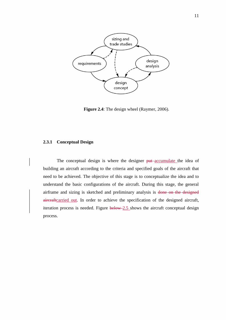
The design of an aircraft begins with the requirements of the target user. Design
is an iterative effort that consist of four elements as shown in figure below(Figure 2.4).
The requirement of an aircraft can be done by prior design trade studies. Then,
requirements can be fulfilled by developing the concepts. After that, design analysis
will frequently points toward new concepts and technologies which will initiate a
whole new design effort (Raymer, 2006).
11
Figure 2.4: The design wheel (Raymer, 2006).
2.3.1 Conceptual Design
The conceptual design is where the designer put accumulate the idea of
building an aircraft according to the criteria and specified goals of the aircraft that
need to be achieved. The objective of this stage is to conceptualize the idea and to
understand the basic configurations of the aircraft. During this stage, the general
airframe and sizing is sketched and preliminary analysis is done on the designed
aircraftcarried out. In order to achieve the specification of the designed aircraft,
iteration process is needed. Figure below 2.5 shows the aircraft conceptual design
process.

12
Figure 2.5: Aircraft conceptual design process (Raymer, 2006)
2.3.1.1 Aerodynamic Analysis
The aerodynamic analysis of an aircraft is very important to determine its
flying qualities. Generally, lift, drag and moment of the aircraft are the important
aerodynamic parameters of an aircraft. To determine these parameters, experimental
approach and analytical approach are available methods that can be used. Analytical
method is used to estimate the aerodynamic coefficient of the designed aircraft due to
time constrain.
Analytical approach method is done by using the XFLR5 software developed
by André Deperrois. The XFLR5 software is used to estimate the aerodynamic
characteristic of the aircraft (Meschia, 2008). The software is a fast subsonic airplane
13
prototyping software where it includes the lifting theory (LLT), vortex lattice method
(VLM) and 3D panel method for aerodynamic characteristic estimation.
The XFLR5 software has some limitation where it only consider inviscid flow
for the VLM used. Therefore, XFLR5 results need to be considered as a preliminary
and experimental work since it is not fully supported by the mathematical model.
Besides, the software must be introduce with both the set of polars derived from
viscous analysis of the adopted airfoil and the geometrical model of the lifting
surfaces. Nevertheless, the viscous analysis of the selected airfoil could be obtain by
using the airfoil database by University of Illinois (Meschia, 2008).
United States Air Force Data Compendium known as USAF DATCOM is a
semi-empirical method used to estimate the aerodynamic characteristics. Similarly,
Harris (2007) employed the DATCOM method in his thesis, Aerodynamic Study of
Flow over UAV. Nonetheless, the DATCOM is more suitable in determining
aerodynamic characteristics for aircraft with speed above Mach number of 0.3. In the
dissertation of Master of Science by Trips (2010)[u6], the details of setting up XFLR5
is shown and presented. Therefore, the aerodynamic analysis of the aircraft using the
XFLR5 can be approximated and estimated.
2.3.1.2 Performance Analysis
Preliminary performance analysis must be conducted in aircraft design process
in order to define its general performance and as well to check the efficiency of the
whole propulsion system. The performance analysis are examined through some of
the important parameters which are the power available, power required, thrust
available, thrust required, rate of climb, endurance and range. These parameter can
obtained from the analysis by referring to Aircraft Performance and Design by John
D. Anderson, Jr (1999).

14
2.3.2 Preliminary Design
Preliminary design is where the aircraft design will be redesign and reanalysed
without takes much changing in its original sizing and basic configurations specified
earlier (Raymer, 2006). Further precise analysis especially the structural and
performance analysis is one of the important part in preliminary design. Extra testing
and prototyping are required in order to define the materials, amount of materials,
structure arrangement and propulsion system that will be used in the aircraft design
(Zi Yang, 2015).
In most cases, computer aided design (CAD) is used to do the process of
reshape and reconfigure the general design perfectly and fast. In the meantime, the
fabrication procedure together with cost estimation of the whole design can be
established during the preliminary design process (Zi Yang, 2015).
The preliminary design of the VTOL aircraft follows the step guided by
Raymer (2006) since the aircraft design is identical to typical fixed wing aircraft
design. The aircraft used several different material, thus the aircraft design must be
simplified in order to reduce the time constrain. CAD software such as Solidworks,
AutoCAD Inventor and etc. can be used to do the full scale modelling. Furthermore,
these software provide features to find the actual centre of gravity position and
moment of inertia by giving the material properties value into each parts that have
been designed.

15
2.3.2.1 Accessories Selection
The accessories for a small scale aircraft are referred to its propulsion system,
servo for control surfaces and the power source which in this project electric power is
the main power source (Zi Yang, 2015). The accessories selection is vital since it
involves the mission required by the VTOL aircraft. Furthermore, it will cause
excessive resource usage and affect the aircraft flying performance if the selection is
not conducted properly.
The VTOL aircraft for this project is comparable with the radio-controlled
(RC) model aircraft and mini UAV model, hence the accessories selection can be done
by referring to Boddington (1978) in RC plane model and journals by Rabbey, et al.,
(2013). Analysis such as the parametric study, aerodynamic and performance analysis
are vital in order to help the designer to list the detail specification of the accessories
selection required for the aircraft mission.
2.3.2.2 Material Selection
Materials selection is very important in order to sustain the aircraft shape and
to ease manufacturing process. Most of the materials that been used in RC aircraft are
balsa wood, foam, fibre and etc. The foam stiffness is comparable to balsa wood while
have a cheaper price (Carlos 2017). Nevertheless, the foams do not have strength
strong as balsa wood and low in density. Generally, designer must take the feasibility
of fabrication, mechanical properties and cost of the materials as consideration
(Boddington, 1978) in order to decide which material will be used in each
compartments.
16
2.3.3 Detail Design
Raymer (2006) stated that detail design process is where the production design
or fabrication process are required to be define before fabrication process takes place.
This is done in order to ensure the product which is the aircraft will be produce
accordingly to the specified design. Furthermore, it is to increase working efficiency
during the period of fabrication process takes place.
The detail design of VTOL aircraft is done using Solidworks software. The
process focus on drawing the 3D model of each compartments and accessories of the
aircraft including the major and minor parts. The major part in this process contain
five parts;
1. to draw the ribs of the wing,
2. attachment of the ribs to the spar,
3. attachment of the wing to the body,
4. drawing the fuselage structure and the VTOL motor position.
The minor parts in this process is to draw the components of the aircraft. The
procedures of the fabrication process of the RC aircraft can be done by referring to
Boddington (1978) in Building & Flying Radio Controlled Model Aircraft.
2.4 Fabrication Method
Every completed and inspected aircraft design required fabrication process to
transform the idea poured in the design stage into a real aircraft by following the
planned procedure. The difficulty of the fabrication stage is depend on the aircraft
design itself. Therefore, it is very important to double check the design in order to
avoid difficulties in fabrication stage.

17
The VTOL aircraft concept is comparable to the RC aircraft model specifically
the fixed-wing type of RC aircraft. Hence, the fabrication method can be done by
referring to Boddington (1978) in Building & Flying Radio Controlled Model Aircraft.
It is a good practice to choose simple fabrication process for easier aircraft
maintenance and repair.

18
CHAPTER 3
3 METHODOLOGY
3.1 Flow Chart
Generally, the project flow and the methodology will be discussed accordingly
to the flow chart as shown in( Figure 3.1). The first semester of the project focused
more on study and analysis which will cover from literature review until static stability
analysis. The rest of the scope will be cover in the second semester which will focused
more on fabrication, further analysis and flight test.

19
Figure 3.1: Categorised flow chart
Design and Fabrication of The VTOL UAV
Literature review
- Parametric study
- UAV operation system
Conceptual Design
-Weight estimation
-Airfoil selection
-Preliminary sizing
-Materials selection
-Centre of gravity
-Aerodynamic analysis
-Preliminary performance
-Installation of vertical rotors
Optimization
Preliminary Design
-Modelling
Detail Design
-Final model defined
-Fabrication procedure
Flight Test

20
3.2 Conceptual Design
The whole conceptual idea and design of the UAV are conducted according to
the reference book, Aircraft Design: A Conceptual Approach by Raymer (2006). The
fundamental steps and procedure of the aircraft design process are listed in the
mentioned earlier book. Basically, it conceptual design consists of feasibility study,
preliminary weight estimation, preliminary sizing, aerodynamic analysis, performance
and stability analysis which will be conducted in this project.
3.2.1 Feasibility Study
Feasibility study is vital in the preliminary conceptual design. This study is a
guidance for the aircraft designer to assume the initial specification based on existed
aircraft (name of the aircraft) under the same category. Hence, the first assumption is
not totally accurate. Feasibility study can be carried out by performing the parametric
study. Table below shows the design specification for a VTOL UAV.
Table 3.1 : Design specification and criteria
Wing configuration Fixed wing
Tail configuration Conventional
Weight Less than 3kg
Range 5 km
Endurance 70 min
Propulsion Electric motor
From the parametric study, some parameters are analysed graphically for
initial assumption. The data obtained is presented in Appendix B1. The considerations
that were taken in the graphs are listed as below.
i. Wingspan versus Maximum Take-off Weight (Appendix B2)
21
ii. Fuselage Length versus Maximum Take-off Weight (Appendix B3)
iii. Endurance versus Maximum Take-off Weight (Appendix B4)
iv. Empty Weight versus Maximum Take-off Weight(Appendix B5)
v. Payload versus Maximum Take-off Weight (Appendix B6)
vi. Endurance versus Wing Span (Appendix B8)
vii. Cruising speed versus Maximum Take-off Weight (Appendix B9)[u7]
3.2.2 Weight Estimation
In Raymer (2006), the preliminary weight estimation can be obtained by using
the equation below;
emptyfuelpayloadcrew WWWWW 0 (1)
Since the propulsion system for the VTOL UAV is electric motor, hence, we
could modified the equation (1) by removing all the unnecessary term such as weight
of the crew and fuel. Then, the equation (1) becomes
emptypayload WWW 0 (2)
Before that, we can determine the relationship between gross weight, 𝑊0 and
payload weight 𝑊𝑝𝑎𝑦𝑙𝑜𝑎𝑑 if we could obtain the value of 𝑊𝑒𝑚𝑝𝑡𝑦
𝑊0. Hence, we could
modified equation (2) into equation (3) shown below;
0
0
1W
W
WW
empty
pay load
(3)

22
The value of 0W
Wempty can be obtained from plotting Graph of Empty Weight
versus Total Gross Weight which the graph is shown in Appendix B5. This lead to
equation below
9767.0
673.10
payloadWW (4)
Other than that, we could determine the maximum take-off weight by
examining the wing span of the existing UAV. This could be observe from the
relationship in plotted graph between maximum take-off weight and the wing span.
This lead to equation below;
8.1390515.97 0 Wbw (5)
3.2.3 Preliminary Sizing
The preliminary sizing of an aircraft can be done through scaling and
estimation of each parts required according to Raymer (2006). Generally, all of the
geometry for wing, fuselage, tail and control surfaces is estimated.
3.2.3.1 Wing Sizing

23
Two parameters that are important for the wing sizing of an aircraft which are
the wing chord and the wing span. These two parameters can be used to find the aspect
ratio of the aircraft. There are no specific aspect ratio requirement for a typical but the
lower and high aspect ratio are for high speed and low speed aircraft respectively. It
is recommended to determine the wing chord and wing span of the aircraft by refer to
the parametric study of the existing aircraft. The relationship of these two parameters
can be shown through these two equations below:
w
w
w
ww
S
b
areawing
spanwing
c
b
chordwing
spanwingAR
22
or
(6)
www cbS (7)
3.2.3.2 Fuselage sizing
The fuselage length estimation for the aircraft can either follow the parametric
study or Raymer (2006). It is preferable to use the parametric study to do the
estimation since this aircraft dimension is adapted from existed aircraft. From the
graph of fuselage sizing versus the maximum take-off weight, the equation below
shows the relationship between these two parameters.
cmWL MTOWfuselage (8)
Referring to Raymer (2006), the fuselage length of the aircraft can be
approximated using the equation below.

24
48.071.0 MTOWfuselage WL (9)
3.2.3.3 Tail sizing
There are many variations of tail configurations that can be implemented on
the aircraft design. Some of the examples are shown in the Figure below.
Figure 3.2 : Basic tail configuration of an aircraft (Raymer, 2006)
Generally the tail sizing can be estimated using tail volume coefficient
(Raymer, 2006) and equation (10) shows the vertical tail volume coefficient and
equation (11) shows the horizontal tail volume coefficient.
ww
vtvtvt
Sb
SLV (10)
25
ww
hththt
Sb
SLV (11)
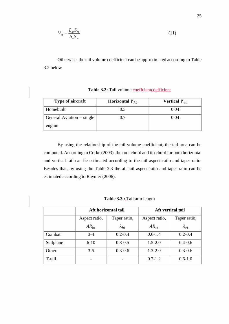
Otherwise, the tail volume coefficient can be approximated according to Table
3.2 below
Table 3.2: Tail volume coeffcientcoefficient
Type of aircraft Horizontal 𝑽𝒉𝒕 Vertical 𝑽𝒗𝒕
Homebuilt 0.5 0.04
General Aviation – single
engine
0.7 0.04
By using the relationship of the tail volume coefficient, the tail area can be
computed. According to Corke (2003), the root chord and tip chord for both horizontal
and vertical tail can be estimated according to the tail aspect ratio and taper ratio.
Besides that, by using the Table 3.3 the aft tail aspect ratio and taper ratio can be
estimated according to Raymer (2006).
Table 3.3 : Tail arm length
Aft horizontal tail Aft vertical tail
Aspect ratio,
𝐴𝑅ℎ𝑡
Taper ratio,
𝜆ℎ𝑡
Aspect ratio,
𝐴𝑅𝑣𝑡
Taper ratio,
𝜆𝑣𝑡
Combat 3-4 0.2-0.4 0.6-1.4 0.2-0.4
Sailplane 6-10 0.3-0.5 1.5-2.0 0.4-0.6
Other 3-5 0.3-0.6 1.3-2.0 0.3-0.6
T-tail - - 0.7-1.2 0.6-1.0

26
The tail root chord, tail tip chord, tail aspect ratio and tail taper ratio can be
computed using equations as follow
For horizontal tail,
ht
htht
S
bAR
2
(12)
htht thtr cc (13)
htht
htr
b
Sc
ht
1
2 (14)
For vertical tail,
vt
vtvt
S
bAR
2
(15)
vtvt tvtr cc (16)
vtvt
vtr
b
Sc
ht
1
2 (17)
3.2.3.4 Control surfaces
Basically, there are three types of control surfaces used by a typical aircraft
which are the aileron, elevator and rudder. These control will control the longitudinal,
lateral and directional stability of the aircraft and also will define the maneuverability
of the aircraft.

27
According to Raymer (2006), the aileron is used to control the rolling
performance of an aircraft and usually the aileron span will extend about 50% to 90%
of the wing span and aileron chord extend from 15% to 25% of the wing chord. Figure
below shows the aileron sizing guideline.
Figure 3.3 : Aileron guideline (Raymer, 2006)
In the other hand, elevator and rudder will control the pitching and yawing
performance of an aircraft respectively. The elevator and rudder span extend from the
tail root up to 90% of the tail span while both of these control surfaces chord cover
25% to 50% of the tail chord (Raymer, 2006).

28
3.2.4 Airfoil Selection
In order for an aircraft to glide during unpowered flight especially during
emergency cases, it is vital to select suitable airfoil nomenclature in order for the wing
to produce enough lift. University of Illinois Urbana–Champaign (UIUC) has big
collection of airfoil coordinate database that could be used in the aerodynamic
analysis. One of the main consideration in the airfoil selection of this project is the
limitation of the fabrication process since it will mostly hand made.
Perfect shape of airfoil may not be achieve without advanced equipment. The
characteristic of the selected airfoil could be approximated by conducting the
aerodynamic analysis using XFLR5 software for further comparisons.
3.2.5 Materials Selection
The aircraft design should have a stable, stiff and strong body which it is
necessary to select material with highest strength to weight ratio (Akshay et. al, 2014).
For RC aircraft, the materials selection for every parts is limited due to the weight of
material. Two common materials that are used to manufacture small RC aircraft are
foam and balsa wood according to Boddington (1978). Balsa, the lightest and most
fragile of woods, is classed as hardwood. It has better flexibility and strength compare
to foam.
Most of its application in RC aircraft is on the aircraft frame and wing for
stable, strong and stiff structure yet accessibility for the maintenance. Nevertheless,
foam could replace the balsa wood if the design used monocoque concept. In addition,
the aircraft usually will have slight difference in total weight since foam is lighter than
balsa wood. In this project, balsa is wood preferable in order to achieve the goal where
the aircraft will have accessibility in maintenance for longer lifespan.

29
Balsa woods grades can be classified into three type; light, medium, high. The
grades represents the density of balsa woods itself (Boddington, 1978). Besides, its
application are varied based on its grade or density. Table below represents the
applications of balsa grades.
Table 3.4: Application of balsa woods based on its grades (Boddingtoon,
1978).
Grade Application(s)
Light Sheet fill-in on built up fuselages.
Semi solid or hollow log fuselages.
Sheet covering (fuselage and wings).
Wing leading edge sheeting.
Cowling blocks.
Light-medium Sheet fill-in on larger models.
Large section leading and trailing edges.
All-sheet tail surfaces.
Solid sheet wings.
Sheet-box construction (e.g. fuselages).
Medium Spacers on box fuselages.
Trailing edges.
Longerons of generous section.
Medium-hard Wing spars of generous section
Auxiliary wing spars.
Longerons.
Small section trailing edges.
Hard Main wing spars.
Longerons of small section.
Auxiliary spars of very small section.
Extra-hard Inset leading edges on side sheet wings.
Wing mainspars of small section.
30
3.2.6 Accessories Selection
In general, accessories are referring to the propulsion system, control surfaces
actuators and power source (Zi Yang, 2015). Nowadays, electrical motor is used as
main propulsion system and electrical servo is used as the control surfaces actuators
(Rabbey et al., 2013). It is recommended to survey on available accessories in the
market by examining their datasheet provide by their manufacturers to be used for
parametric study and preliminary performance analysis.
3.2.7 Preliminary Centre of Gravity and Moment of Inertia Estimation
Approximation of the centre of gravity can be conducted by using the
Solidworks software by giving specific density of the materials that will be used during
the modelling process. Modelling included all the accessories such as the propulsion
system and control surfaces actuators. The VTOL position is vital in the cg
management in order to reduce chances of instability during take-off.
3.2.8 Aerodynamic Analysis
For preliminary aerodynamic analysis, XFLR5 software are used since it is
suitable for an aircraft that operates at low Reynold number. XFLR5 could provide the
aerodynamic characteristics of the designed wing and tail with less computing time.
Besides, we could also find the reference velocity at particular angle of attack
while consider the aircraft will cruise under steady flight using equation (18).

31
LwCS
WV
2
10 (18)
3.2.8.1 XFLR5
The steps and procedures of the XFLR5 software can be found in its official
website (Deperrois, 2012). The airfoil shape which is saved in .dat file is imported into
the software. Based on selected range of Reynolds numbers, airfoil’s aerodynamic
characteristics can be approximated. Then, finite wing is inserted to find its
aerodynamic characteristics by selecting Fixed Speed configurations. The procedures
are repeated for tail aerodynamic analysis. Basic setup is referred to Deperrois (2002)
as listed in table below.
Table 3.4 : Reference setup for XFLR5 software
Minimum Reynolds Number 133,00
Maximum Reynolds Number 813,00
Increment Reynolds Number 10,000
Mach 0
NCrit 9
Minimum Alpha -10ᵒ
Maximum Alpha 20o
Increment Alpha 0.5o
Polar Type Type 1 (Fixed Speed)
Reference Velocity 10 m/s
Density 1.225 kg/m3
Kinematic Viscosity 1.7894 x 10⁻⁵ kg/ms

32
In this analysis, the 3D panel method and vortex lattice method (VLM) is taken
into consideration as the viscosity effect is included for both of these methods
according to Zi Yang (2015).
3.2.9 Preliminary Performance Analysis
The preliminary performance analysis of an aircraft can be conducted by
referring to Aircraft Performance and Design by Anderson (1999). The book guide the
user to define the performance of a designed aircraft. In general, the preliminary
performance analysis will cover the drag polar, power, thrust and the range as well as
endurance of the designed aircraft.
3.2.9.1 Drag Polar
Most of the aircraft designers will likely to use the drag polar of an aircraft to
determine the performance characteristic and flying qualities of an aircraft. The drag
polar describe the relationship between the total lift coefficient and total drag
coefficient of an aircraft. The drag polar can be used to calculate the lift to drag ratio
and zero lift drag coefficient.
The lift to drag ratio or L/D ratio is the amount of lift created aerodynamically
from the wing of the aircraft divided by the aerodynamic drag. Since the lift calculated
is set by the aircraft’s weight, a higher L/D ratio is preferable. This is because higher
L/D ratio will deliver lift with lower drag which will result in better fuel economy in
aircraft performance. Zero lift drag coefficient, 𝐶𝑑𝑜 is a coefficient of drag produced
when there is no lift produced on the wing. 𝐶𝑑𝑜 is part of total drag coefficient which

33
represented in equation below. Therefore, drag coefficient, 𝐶𝑑 produced by the aircraft
during flying at different speed can be calculated when 𝐶𝑑𝑜 is available.
eAR
CCC l
dd
2
0 (19)
3.2.9.2 Power Available and Required
Power available is referred to the power produced by the propulsion system
with its specific efficiency of the aircraft. The aircraft is comparable to the latest mini
UAV which powered by electrical motor (Rabbey et. al, 2013). Basically, the power
available will not be the same with the power output of the motor as each motor will
have its own different efficiency which mostly affected by the propeller that been used.
The equation below shows the relationship between the power available and power
output of the motor.
0PP propa (20)
The performance of the electric motor could be done by using the MotoCalc
software. By using the software, we could approximate the motor performance based
on the percentage of throttle power applied, aircraft flying velocity, electric motor
controller used and the battery source. Figure 3.4 and 3.5 shows the graphical user
interface for MotoCalc software.
34
[u8]
Figure 3.4 : XFLR5 interface for motor performance
[u9]
Figure 3.5 : XFLR5 interface for motor performance graph analysis
The propeller characteristic does play an important role in determining the
actual power available, 𝑃𝑎 (Yew, 2009). Therefore, it is important to study the
propeller characteristic in order to approximate the propeller efficiency, 𝜂𝑝𝑟𝑜𝑝. By
referring to UIUC Propeller Database (2017), the propeller efficiency, 𝜂𝑝𝑟𝑜𝑝 could be
obtained.
35
Power required is referring to the power required for an aircraft to fly at certain
airspeed with its total drag force. In general, cruising is the common state taken as the
consideration in the analysis. The total power required will divided into two parts
which are the power to overcome parasite drag and power to overcome induced drag.
The equations are shown below.
Total drag,
iDDD CCC ,0, (21)
Power required to overcome parasite drag,
VCSVP DwR 0,
20,
2
1 (22)
Power required to overcome induced drag,
VCSVP iDwiR ,
2,
2
1 (23)
Total power required,
iRRR PPP ,0, (24)
The induced drag coefficient is in a function of lift coefficient (Anderson,
1999) which the relation shown as below,
36
w
LiD
eAR
CC
2
, (25)
3.2.9.3 Thrust Available and Required
Thrust available is the ability for propulsion system to produce forward thrust.
Thrust is a function of power and the aircraft speed, thus thrust available can be
obtained using the power available value using equation below
V
PT a
a (26)
Similarly, the total thrust required is a combination of force to overcome
parasite drag and induced drag. The equations are given by
Thrust required to overcome parasite drag,
V
PCSVT
RDwR
0,0,
20,
2
1 (27)
Thrust required to overcome induced drag,
V
PCSVT
iRiDwiR
,,
2,
2
1 (28)

37
Total thrust required,
V
PTTT R
iRRR ,0, (29)
3.2.9.4 Range
Range is the distance travel by the aircraft with such amount of power supplied.
The range for electrical propulsion system can be obtain by using the Breguet equation
(Anderson, 2009) which derived as shown in equations below
0
6.3W
CU
C
CR elel
D
Lsys
(30)
Maximum range is given by
0max
6.3W
CU
C
CR elel
D
Lsys
(31)
Where 𝑅 and 𝑅𝑚𝑎𝑥 unit is in km
The electric power supplied not only supplied the whole propulsion system but
also supplied to another subsystem such as the control system. Therefore, the range
equation can be derive as shown in equations below.

38
V
I
U
W
C
C
CR
subel
elsysD
L
el
0
6.3 (32)
While maximum range could be written as
V
I
U
W
C
C
CR
subel
elsysD
L
el
0
max
6.3 (33)
Where 𝑅 and 𝑅𝑚𝑎𝑥 unit is in kilometre
3.2.9.5 Endurance
Endurance of an aircraft is the performance of an aircraft to stay in its flight
with given power supplied. By using the same approach, the derivation for endurance,
𝐸 could be written as
elelsysw
D
L CUW
S
C
CE
3
02
3
260 (34)
While maximum endurance is given by

39
elelsysw
D
L CUW
S
C
CE
3
0max
2
3
max2
60 (35)
Where 𝐸 and 𝐸𝑚𝑎𝑥 unit is in minutes
Previously, using the same consideration in determine range equation, the
endurance equation could be written as
subelelsys
wD
L
elelsys
IUS
W
C
C
CUE
30
2
32
1
60 (36)
While maximum endurance is given by
subelelsys
wD
L
elelsys
IUS
W
C
C
CUE
30
max
2
3max
21
60 (37)
Where 𝐸 and 𝐸𝑚𝑎𝑥 unit is in minutes
3.3 Optimization
The aircraft design is required to be optimised in order to achieve the best
configuration with the desired performance specification after all the preliminary
analysis done (Zi Yang, 2015). The optimization required modifications to the aircraft
40
design in particular it frequently requires a revised or new design layout (Raymer,
2006). For greater optimization, the drawing is revised after number of iterations until
the design meets the goals of the aircraft.
3.4 Preliminary Design, Detail Design and Fabrication
Preliminary design will begin when the major changes are concluded (Raymer,
2006). For example, the tail configurations of an aircraft has been decided by choosing
the conventional tail. Besides some minor revisions on the design will occur in order
to meet the goals. Nevertheless, these minor changes are stopped after decision is made
to freeze the configurations of the aircraft.
Modelling of the aircraft can be conducted by using Solidworks software by
including all of the accessories required. Fabrication procedure is established when
the modelling process is completed where the methods and steps to fabricate the
aircraft will be listed. The procedures to fabricate the aircraft is listed in Appendix C.
The items and materials required is listed in Appendix D.
3.5 Validation Works and Flight Test
Finally, the aircraft flying qualities especially the VTOL mechanisms will be
conducted by using the radio telemetry. Manual mode will be used during the flight
test and no stabilization mode is used since there is no augmentation system will be
used. Aim of the flight test is to make the VTOL RC aircraft take off successfully.

41
CHAPTER 4
4 RESULTS AND DISCUSSIONS

42
CHAPTER 5
5 CONCLUSION

43
6 REFERENCES
Abdelrahman M. M., Elnomrossy M. M., Ahmed M. R., (2009). Development of Mini
Unmanned Air Vehicles. 13th International Conference on Aerospace Sciences
& Aviation Technology, ASAT – 13.
Akshay B., Divyesh K., Dr. Jayaramulu C., (2014). Material Selection for Unmanned
Aerial Vehicle. International Journal of Mechanical Engineering and
Technology, Volume 5, Issue 8, August, PP. 34-40.
Anderson J. D., (1999). Aircraft Performance and Design. Maryland, United State:
WCB Mc Graw Hill.
Boddington D., (1978). Building & Flying Radio Controlled Model Aircraft. Argus
Books.
Corke, (2003). Design of Aircraft. Upper Saddle River, NJ: Pearson Education, Inc.
Deperrois A., (February 2017). XFLR5. Retrieved from: www.xflr5.com.
Meschia F., (2008). Model Analysis with XFLR5. Radio Controlled Soaring Digest.
Volume 25 No. 2. Feb 2008. PP. 27-51.
Harris A., (2007). Aerodynamic Study of Flow over UAV. (Bachelor’s Dissertation).
Universiti Teknologi Malaysia
Magnotta J., (2015, Jan 5). Use of Drone in GIS. Retrieved from www.gislounge.com.
Carpenter P., (November, 2016). Retrieved from www.rc-airplane-world.com
Rabbey Md. F., Papon E.A., Rumi A.M., Monerujjaman H.Md., Nuri F.H., (2013).
Technical Development of Design & Fabrication of an Unmanned Aerial
Vehicle. IOSR Journal of Mechanical and Civil Engineering (IOSR-JMCE).
Volume 7. Jul - Aug 2013. PP 36-46.
Raymer D. P., (2006). Aircraft Design: A Conceptual Approach. American Institute
of Aeronautics and Astronautics
44
Trips B., (2010). Aerodynamic Design and Optimization of a Long Range Mini – UAV.
(Master of Science Thesis). Delft University of Technology.
Yew C. P., (2009). Synthesis and Validation of Flight Control for UAV. (Bachelor’s
Dissertation). University of Minnesota.
Zafirov D., (2013). Autonomous VTOL Joined-Wing UAV. AIAA Atmospheric Flight
Mechanics (AFM) Conferences. Boston, MA, 19-22 August. American Institute
of Aeronautics and Astronautics, Inc.
Zaryab S., Abubakar R., (2016). Applications of UAV in Daily Life. AIAA SciTech
Forum. San Diego, California, 4-8 January 2016. American Institute of
Aeronautics and Astronautics, Inc.
Zi Y., (2015). Design and Fabrication of Low Speed Powered Glider. (Bachelor’s
Dissertation). Universiti Teknologi Malaysia.

45
APPENDIX A
Gantt Chart
Weeks of semester 1 1 2 3 4 5 6 7 8 9 10 11 12 13 14 15 16
Topic confirmation
Discussion with supervisor about the research scope
Meeting arrangement
Literature review
Definition study
Parametric study
On board system study
Fabrication method study
Conceptual design
Weight estimation
Initial sizing
Modelling
Centre of gravity estimation
Aerodynamic analysis
Lift, Drag, Moment
Performance analysis
Power required
Power and thrust required
Range and endurance
Stability analysis
Static stability
1st draft preparation
VIVA 1

46
APPENDIX A[u10]
Gantt Chart
Weeks of semester 2 1 2 3 4 5 6 7 8 9 10 11 12 13 14 15[u11]
Scope confirmation
Discussions about the panels feedback from VIVA1
Meeting arrangement
Optimization
Preliminary Design
Preliminary Analysis
Aerodynamic Analysis
Performance Analysis
Static Stability Analysis
Dynamic Stability Analysis
Longitudinal Derivatives
Lateral Derivatives
Preliminary & Detail Design
Complete modelling
Fabrication
Flight Test
Final draft preparation
VIVA 2

47
APPENDIX B1
Parametric study
Model MTOW, kg Empty weight, kg
Payload, kg Fuselage length, mm
Wing span, mm
Cruising speed, m/s
Endurance, mins
1 Skywalker 1680 2.3 1.115 1.185 1180 1720 25 70
2 Zeta Sky Observer FPV 4.991 1.45 3.541 1511 2000 65
3 Skywalker Revolution FPV 2.68 1.115 1.565 1200 1720 25 65
4 Skywalker Naja FPV 3 1.5 1.5 948 1920 27 60
5 AXN Floater-Jet EPO 2.549 1.05 1.499 830 1290 23 30
6 X-Large EPP 2.889 1.2 1.689 1150 1800 30
7 HobbyKing Bixler v1.1 1.935 0.65 1.285 925 1400 30
8 HobbyKing Bixler 2 EPO 3.207 0.76 2.447 963 1500 30
9 HobbyKing Bix3 Trainer 2.652 0.89 1.762 948 1550 30
10 HobbyKing Sky Eye 2.532 1.35 1.182 1050 2000 40
11 Durafly Tundra 3.51 1.15 2.36 1190 1300 30
12 HobbyKing Mini SkyHunter 1.917 0.83 1.087 750 1238 13 25
13 HobbyKing Breeze Glider 2.325 0.63 1.695 1020 1400 30
14 AAI RQ-7 Shadow 3.971 2 1.971 1630 2000 46 35
15 Firstar 2000 V2 3.278 1.05 2.228 1044 2000 30
16 Firstar 1600 3.184 0.95 2.234 1050 1600 28
17 E-Do Model Sky Eye 3.083 1.95 1.133 900 1890 30
18 Skywalker WALL E2000 5.825 2.15 3.675 1120 2030 16 35
19 E-Do Model Sky Eye Twin 3.373 2.1 1.273 900 1890 30
20 Cumulus One 2.2 1.6 0.6 950 1650 40 150
21 ALTI Transition 15 14 1 1500 2760 50 360

48
APPENDIX B2
Graph of Wingspan versus Maximum Take-Off Weight
y = 97.515x + 1390.8
0
500
1000
1500
2000
2500
3000
0 2 4 6 8 10 12 14 16
Win
gsp
an (
mm
)
MTOW (kg)
Wingspan (mm) versus MTOW (kg)

49
APPENDIX B3
Graph of Fuselage Length versus Maximum Take-Off Weight
y = 46.613x + 914.18
0
200
400
600
800
1000
1200
1400
1600
1800
0 2 4 6 8 10 12 14 16
Fuse
lage
len
gth
(m
m)
MTOW (kg)
Fuselage length (mm) versus MTOW (kg)

50
APPENDIX B4
Graph of Endurance versus Maximum Take-Off Weight
y = 22.998x - 24.957
0
50
100
150
200
250
300
350
400
0 2 4 6 8 10 12 14 16
End
ura
nce
(m
in)
MTOW (kg)
Endurance (min) versus MTOW (kg)

51
APPENDIX B5
Graph of Empty Weight versus Maximum Take-Off Weight
y = 0.9767x - 1.673
0
2
4
6
8
10
12
14
16
0 2 4 6 8 10 12 14 16
Emp
ty w
eigh
t (k
g)
MTOW (kg)
Empty weight (kg) versus MTOW (kg)

52
APPENDIX B6
Graph of Payload versus Maximum Take-off Weight
y = 0.0233x + 1.673
0
0.5
1
1.5
2
2.5
3
3.5
4
0 2 4 6 8 10 12 14 16
Pay
load
(kg
)
MTOW (kg)
Payload (kg) versus MTOW (kg)

53
APPENDIX B7
Graph of Endurance versus Wingspan
y = 0.1387x - 183.42
-50
0
50
100
150
200
250
300
350
400
0 500 1000 1500 2000 2500 3000
End
ura
nce
(m
in)
Wingspan (mm)
Endurance (min) versus Wingspan (mm)

54
APPENDIX B8
Graph of Cruising Speed versus Wingspan
y = 0.0191x - 5.2328
0
10
20
30
40
50
60
0 500 1000 1500 2000 2500 3000
Fuse
lage
len
gth
(m
m)
Wingspan(mm)
Cruising speed (m/s) versus Wingspan (mm)

55
APPENDIX C
Fabrication procedures
56
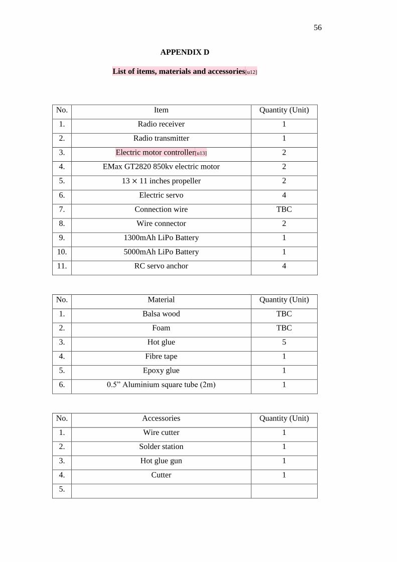
APPENDIX D
List of items, materials and accessories[u12]
No. Item Quantity (Unit)
1. Radio receiver 1
2. Radio transmitter 1
3. Electric motor controller[u13] 2
4. EMax GT2820 850kv electric motor 2
5. 13 × 11 inches propeller 2
6. Electric servo 4
7. Connection wire TBC
8. Wire connector 2
9. 1300mAh LiPo Battery 1
10. 5000mAh LiPo Battery 1
11. RC servo anchor 4
No. Material Quantity (Unit)
1. Balsa wood TBC
2. Foam TBC
3. Hot glue 5
4. Fibre tape 1
5. Epoxy glue 1
6. 0.5” Aluminium square tube (2m) 1
No. Accessories Quantity (Unit)
1. Wire cutter 1
2. Solder station 1
3. Hot glue gun 1
4. Cutter 1
5.