design summary lmz1xxx and lmz2xxx power module family ... · design summary lmz1xxx and lmz2xxx...
TRANSCRIPT
SNAA214B LMZ1 and LMZ2 Power Module Design Summary Texas Instruments Page 1 1/19/2016
Design Summary LMZ1xxx and LMZ2xxx Power Module Family
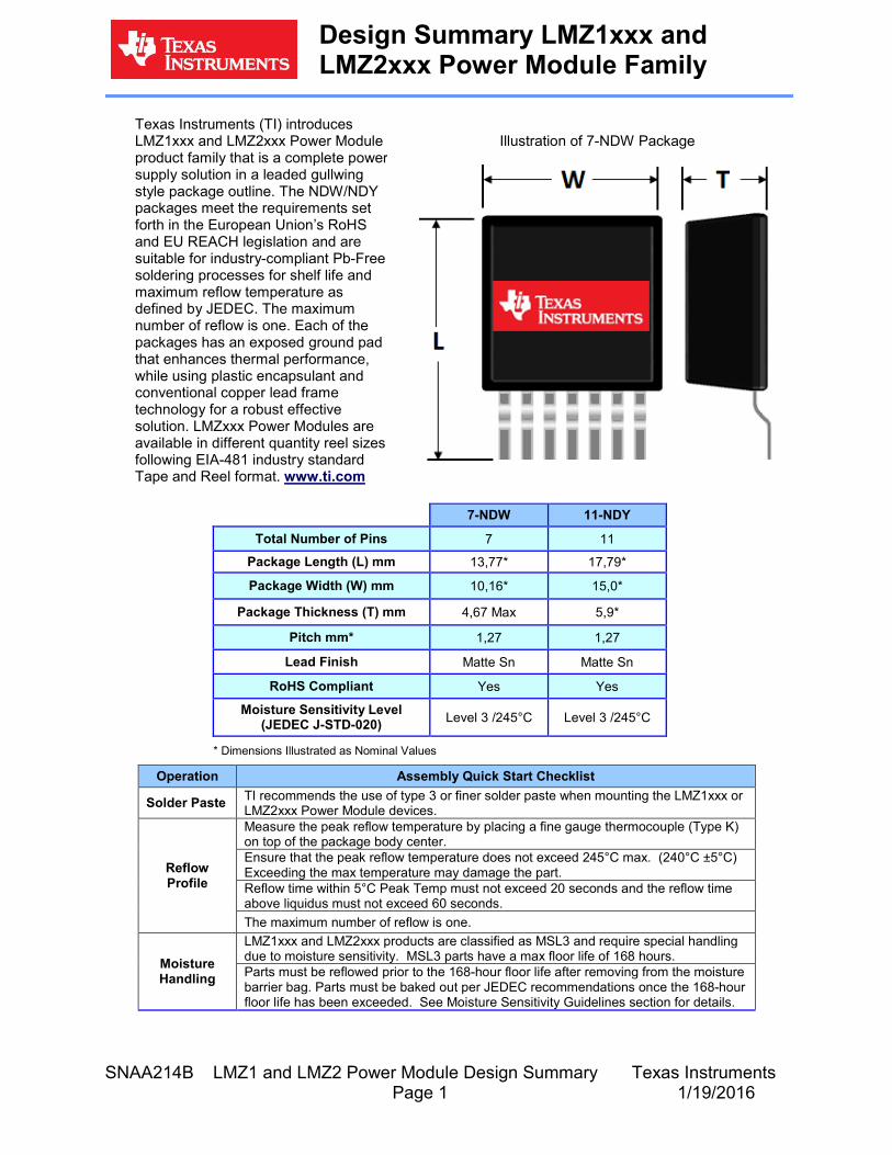
Texas Instruments (TI) introduces LMZ1xxx and LMZ2xxx Power Module product family that is a complete power supply solution in a leaded gullwing style package outline. The NDW/NDY packages meet the requirements set forth in the European Union’s RoHS and EU REACH legislation and are suitable for industry-compliant Pb-Free soldering processes for shelf life and maximum reflow temperature as defined by JEDEC. The maximum number of reflow is one. Each of the packages has an exposed ground pad that enhances thermal performance, while using plastic encapsulant and conventional copper lead frame technology for a robust effective solution. LMZxxx Power Modules are available in different quantity reel sizes following EIA-481 industry standard Tape and Reel format. www.ti.com
Illustration of 7-NDW Package
7-NDW 11-NDY
Total Number of Pins 7 11
Package Length (L) mm 13,77* 17,79*
Package Width (W) mm 10,16* 15,0*
Package Thickness (T) mm 4,67 Max 5,9*
Pitch mm* 1,27 1,27
Lead Finish Matte Sn Matte Sn
RoHS Compliant Yes Yes Moisture Sensitivity Level
(JEDEC J-STD-020) Level 3 /245°C Level 3 /245°C
* Dimensions Illustrated as Nominal Values
Operation Assembly Quick Start Checklist
Solder Paste TI recommends the use of type 3 or finer solder paste when mounting the LMZ1xxx or LMZ2xxx Power Module devices.
Reflow Profile
Measure the peak reflow temperature by placing a fine gauge thermocouple (Type K) on top of the package body center. Ensure that the peak reflow temperature does not exceed 245°C max. (240°C ±5°C) Exceeding the max temperature may damage the part. Reflow time within 5°C Peak Temp must not exceed 20 seconds and the reflow time above liquidus must not exceed 60 seconds. The maximum number of reflow is one.
Moisture Handling
LMZ1xxx and LMZ2xxx products are classified as MSL3 and require special handling due to moisture sensitivity. MSL3 parts have a max floor life of 168 hours. Parts must be reflowed prior to the 168-hour floor life after removing from the moisture barrier bag. Parts must be baked out per JEDEC recommendations once the 168-hour floor life has been exceeded. See Moisture Sensitivity Guidelines section for details.
SNAA214B LMZ1 and LMZ2 Power Module Design Summary Texas Instruments Page 2 1/19/2016
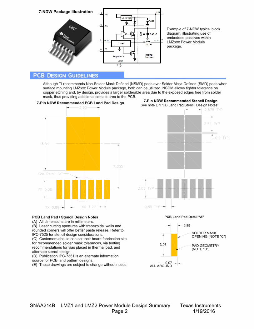
7-NDW Package Illustration
Example of 7-NDW typical block diagram, illustrating use of embedded passives within LMZxxx Power Module package.
Although TI recommends Non-Solder Mask Defined (NSMD) pads over Solder Mask Defined (SMD) pads when surface mounting LMZxxx Power Module package, both can be utilized. NSDM allows tighter tolerance on copper etching and, by design, provides a larger solderable area due to the exposed edges free from solder mask, thus providing additional contact area to the PCB.
7-Pin NDW Recommended PCB Land Pad Design
7-Pin NDW Recommended Stencil Design See note E “PCB Land Pad/Stencil Design Notes”
PCB Land Pad / Stencil Design Notes (A) All dimensions are in millimeters. (B) Laser cutting apertures with trapezoidal walls and rounded corners will offer better paste release. Refer to IPC-7525 for stencil design considerations. (C) Customers should contact their board fabrication site for recommended solder mask tolerances, via tenting recommendations for vias placed in thermal pad, and alternate stencil design. (D) Publication IPC-7351 is an alternate information source for PCB land pattern designs. (E) These drawings are subject to change without notice.
PCB Land Pad Detail “A”
(NOTE "D")PAD GEOMETRY
SOLDER MASKOPENING (NOTE "C")
0,07ALL AROUND
3,06
0,89
SNAA214B LMZ1 and LMZ2 Power Module Design Summary Texas Instruments Page 3 1/19/2016
TI recommends the use of type 3 or finer solder paste when mounting the LMZxxx Power Module devices due to the following advantages:
• Contains flux to aid wetting of the solder to the PCB land. • The adhesive/tacky properties of the paste will hold the component in place during
manufacture. • Paste by volume contains ≈50% metal load typically and can be varied by print volume for
calculating the amount of paste necessary to form a given solder joint. Power module packages are typically manufactured with printed thermal pad volumes between 50% and 80% by area to facilitate wetting of the periphery solder joints and also to maintain a standoff from the board surface.
• Paste contributes to the final volume of metal in the joint, and thus can be varied to give an optimum joint.
• Paste selection is normally driven by overall system assembly requirements. In general, the "no clean" compositions are preferred due to the difficulty in cleaning under the mounted components.
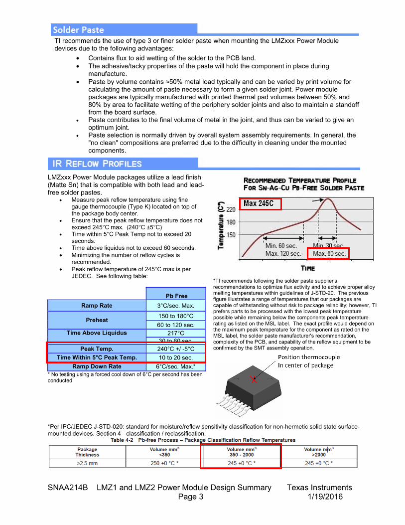
LMZxxx Power Module packages utilize a lead finish (Matte Sn) that is compatible with both lead and lead-free solder pastes.
• Measure peak reflow temperature using fine gauge thermocouple (Type K) located on top of the package body center.
• Ensure that the peak reflow temperature does not exceed 245°C max. (240°C ±5°C)
• Time within 5°C Peak Temp not to exceed 20 seconds.
• Time above liquidus not to exceed 60 seconds. • Minimizing the number of reflow cycles is
recommended. • Peak reflow temperature of 245°C max is per
JEDEC. See following table:
Pb Free Ramp Rate 3°C/sec. Max.
Preheat 150 to 180°C 60 to 120 sec.
Time Above Liquidus 217°C 30 to 60 sec.
Peak Temp. 240°C +/ -5°C Time Within 5°C Peak Temp. 10 to 20 sec.
Ramp Down Rate 6°C/sec. Max.* * No testing using a forced cool down of 6°C per second has been conducted
*TI recommends following the solder paste supplier's recommendations to optimize flux activity and to achieve proper alloy melting temperatures within guidelines of J-STD-20. The previous figure illustrates a range of temperatures that our packages are capable of withstanding without risk to package reliability; however, TI prefers parts to be processed with the lowest peak temperature possible while remaining below the components peak temperature rating as listed on the MSL label. The exact profile would depend on the maximum peak temperature for the component as rated on the MSL label, the solder paste manufacturer's recommendation, complexity of the PCB, and capability of the reflow equipment to be confirmed by the SMT assembly operation.
*Per IPC/JEDEC J-STD-020: standard for moisture/reflow sensitivity classification for non-hermetic solid state surface-mounted devices. Section 4 - classification / reclassification.
SNAA214B LMZ1 and LMZ2 Power Module Design Summary Texas Instruments Page 4 1/19/2016
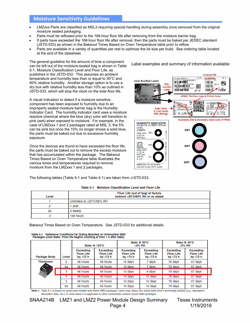
• LMZxxx Parts are classified as MSL3 requiring special handling during assembly once removed from the original
moisture sealed packaging. • Parts must be reflowed prior to the 168-hour floor life after removing from the moisture barrier bag. • If parts have exceeded the 168-hour floor life after removal, then the parts must be baked per JEDEC standard
(JSTD-033) as shown in the Bakeout Times Based on Oven Temperature table prior to reflow. • Parts are available in a variety of quantities per reel to optimize the lot size per build. See ordering table located
at the end of the datasheet.
The general guideline for the amount of time a component can be left out of the moisture-sealed bag is shown in Table 5-1, Moisture Classification Level and Floor Life, as published in the JSTD-033. This assumes an ambient temperature and humidity less than or equal to 30°C and 60% relative humidity. Another storage option is to use a dry box with relative humidity less than 10% as outlined in JSTD-033, which will stop the clock on the total floor life. A visual indication to detect if a moisture sensitive component has been exposed to humidity due to an improperly sealed moisture barrier bag is the Humidity Indicator Card. The humidity indicator card uses a moisture reactive chemical where the blue (dry) color will transition to pink (wet) when exposed to moisture. For example, in the case of LMZxxx 1 and 2 packages rated at MSL 3, the 5% can be pink but once the 10% no longer shows a solid blue, the parts must be baked out due to excessive humidity exposure. Once the devices are found to have exceeded the floor life, the parts must be baked out to remove the excess moisture that has accumulated within the package. The Bakeout Times Based on Oven Temperature table illustrates the various times and temperatures required to remove moisture from the LMZxxx 1 and 2 packages.
Label examples and summary of information available:
The following tables (Table 5-1 and Table 4-1) are taken from J-STD-033.
Bakeout Times Based on Oven Temperature. See JSTD-033 for additional details.
SNAA214B LMZ1 and LMZ2 Power Module Design Summary Texas Instruments Page 5 1/19/2016
• Reuse of a removed package is not recommended. • Utilize a new package for the repair process (see the
following package replacement procedure). • The new package should be kept dry and should not
exceed stated floor life after dry pack has been opened. (Refer to the Moisture Sensitivity Guidelines section)
• If failure analysis is required from TI, we recommend returning the entire assembly with part mounted or a cutout of the section with the part still mounted. Please contact your local TI sales representative for shipping information.
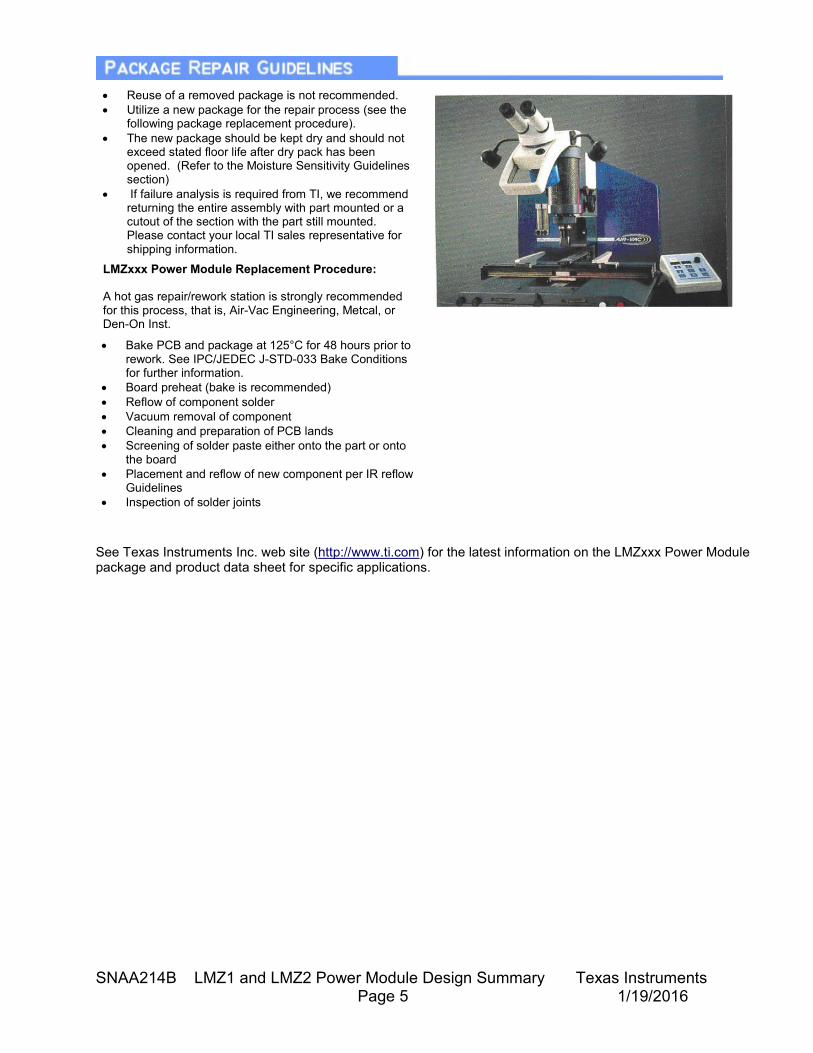
LMZxxx Power Module Replacement Procedure:
A hot gas repair/rework station is strongly recommended for this process, that is, Air-Vac Engineering, Metcal, or Den-On Inst.
• Bake PCB and package at 125°C for 48 hours prior to rework. See IPC/JEDEC J-STD-033 Bake Conditions for further information.
• Board preheat (bake is recommended) • Reflow of component solder • Vacuum removal of component • Cleaning and preparation of PCB lands • Screening of solder paste either onto the part or onto
the board • Placement and reflow of new component per IR reflow
Guidelines • Inspection of solder joints
See Texas Instruments Inc. web site (http://www.ti.com) for the latest information on the LMZxxx Power Module package and product data sheet for specific applications.
SNAA214B LMZ1 and LMZ2 Power Module Design Summary Texas Instruments Page 6 1/19/2016
Q. Is package rework possible? Are tools available? A. Yes, rework is possible, and there are several semi-automatic SMT rework machines and profiles available. However, TI does not guarantee the reliability of re-used packages. It is best to discard and replace any package that fails test. Q. What alignment accuracy is possible? A. Alignment accuracy for package is dependent upon board-level pad tolerance, placement accuracy, and lead position tolerance. Nominal lead position tolerances are specified at ±50 microns. These packages are self-aligning during solder reflow, so final alignment accuracy may be better than placement accuracy. To maximize the self-alignment effect of LMZxxx Power Module Package it is recommended that the maximum reflow temperature specified for the solder paste not be exceeded. A good guide is to subject the PCB to a temperature ramp not exceeding 4°C per second. Q. What size land pad for these packages should I design on my board? A. Pad size is the key to board-level reliability, and Texas Instruments strongly recommends following the land pattern design included in this design summary. Q. Can the solder joints be inspected after reflow? A. Many customers are achieving satisfactory results during process setup with tomographic X-ray techniques. Q. What factors can increase LMZxxx Power Module assembly yields? A. TI recommends the following: • Solder Paste Quality - Uniform viscosity and texture. Free from foreign material. Paste must be protected from drying out on the solder stencil. • PCB Quality - Clean, flat, plated or coated solder land area. Attachment surface must be clean and free of solder mask residue. • Placement Accuracy - LMZxxx Power Module packages have some ability to self-center as long as a major portion (more than 50 percent) of the lead finger is in contact with the solder paste covered land area on the board. • A Solder Reflow Profile should be developed for each PCB type monitoring that the peak reflow temperature is not exceeded. • Solder Volume is important to ensure optimum contact of all intended solder connections. • Excess amount of solder paste during customer’s board assembly may produce solder squeeze out and potential shorting. TI recommends optimizing the amount of solder paste on the bottom side by using a recommended stencil design.
Q. Is TI developing a RoHS version of LMZxxx Power Module? A. Yes, Texas Instruments has developed the package to comply with all RoHS / lead-free environmental policies. Check with your local TI Field Sales representative for sample availability. Q. Any EMI concerns for traces under the package and how can customers design their board to minimize EMI? A. EMI can be controlled by minimizing any complex current loops on the PCB trace. Some helpful hints include: • Solid ground and power planes can be used in the design. Partitioned ground and power planes must be avoided. These ground and power partitions may create complex current loops increasing radiation. • Avoid right angles or "T" crosses on the trace. Right angles can cause impedance mismatch and increase trace capacitance causing signal degradation. • Minimize power supply loops by keeping power and ground traces parallel and adjacent to each other. Significant package EMI can be reduced by using this method. Q. What are the time requirements for floor life on these packages? A. Moisture absorption is a significant factor in popcorn type defects during reflow. Since this package is classified as moisture level 3, the 1st and 2nd reflow have to be completed within 168 hours after opening the moisture barrier bag. If this time frame cannot be met, it is highly recommended to bake the packages at 125°C for 48 hours prior to reuse. IPC/JEDEC J-STD-33 provides additional information as to shelf life, floor life, and reworking MSL classified SMT devices. Q. Can this module be mounted by wave solder? A. No, this package is designed for surface mount process with peak reflow temperature not to exceed 245°C. Immersing the part into a wave solder process is not recommended.
SNAA214B LMZ1 and LMZ2 Power Module Design Summary Texas Instruments Page 7 1/19/2016
Revision History
Revision Date Description
October 2015 Added “The maximum number of reflow is one” on page 1.
Removed the column 9-NES (package option) from the table on page 1.
Removed “Q. Can customer mount LMZxxx Power Modules packages on
the bottom side of the PCB?” on page 6” in the Questions & Answers section

SNAA214B LMZ1 and LMZ2 Power Module Design Summary Texas Instruments Page 8 1/19/2016
INTERNET
TI Semiconductor Product Information Center Home Page support.ti.com
TI E2E Community Home Page e2e.ti.com
PRODUCT INFORMATION CENTERS Americas Asia Phone +1(512) 434-1560 Phone
Toll Free Number
Brazil Note: Toll free numbers may not support mobile and IP phones.
Phone 0800-891-2616 Australia 1-800-999-084
China 800-820-8682
Mexico Hong Kong 800-96-5941
Phone 0800-670-7544 India 000-800-100-8888
Indonesia 001-803-8861-1006
Fax +1 (972)927-6377 Korea 080-551-2804
Internet/Email support.ti.com/sc/pic/americas.htm Malaysia 1-800-80-3973
Europe, Middle East, and Africa New Zealand 0800-446-934
Phone Philippines 1-800-765-7404
European Free Call 00800-ASK-TEXAS Singapore 800-886-1028
(00800 275 83927) Taiwan 0800-006800
International +49 (0) 8161 80 2121 Thailand 011-800-886-0010
Russian Support +7 (4) 95 98 10 701 International +86-21-23073444
Fax +86-21-23073686 Note: The European Free Call (Toll Free) number is not active in all countries. If you have technical difficulty calling the free call number, please use the international number above.
Email [email protected]
Internet support.com/sc/pic/asia.htm Fax +(49) (0) 8161 80 2045
Internet www.ti.com/asktexas
Direct Email [email protected]
Japan
Phone Toll Free Number
Domestic 0120-92-0036
Fax International +81-3-33-44-5317
Domestic 0120-81-0036
Internet/Email Domestic www.tij.co.jp/pic International support.ti.com/sc/pic/japan.htm
IMPORTANT NOTICE
Texas Instruments Incorporated and its subsidiaries (TI) reserve the right to make corrections, enhancements, improvements and otherchanges to its semiconductor products and services per JESD46, latest issue, and to discontinue any product or service per JESD48, latestissue. Buyers should obtain the latest relevant information before placing orders and should verify that such information is current andcomplete. All semiconductor products (also referred to herein as “components”) are sold subject to TI’s terms and conditions of salesupplied at the time of order acknowledgment.TI warrants performance of its components to the specifications applicable at the time of sale, in accordance with the warranty in TI’s termsand conditions of sale of semiconductor products. Testing and other quality control techniques are used to the extent TI deems necessaryto support this warranty. Except where mandated by applicable law, testing of all parameters of each component is not necessarilyperformed.TI assumes no liability for applications assistance or the design of Buyers’ products. Buyers are responsible for their products andapplications using TI components. To minimize the risks associated with Buyers’ products and applications, Buyers should provideadequate design and operating safeguards.TI does not warrant or represent that any license, either express or implied, is granted under any patent right, copyright, mask work right, orother intellectual property right relating to any combination, machine, or process in which TI components or services are used. Informationpublished by TI regarding third-party products or services does not constitute a license to use such products or services or a warranty orendorsement thereof. Use of such information may require a license from a third party under the patents or other intellectual property of thethird party, or a license from TI under the patents or other intellectual property of TI.Reproduction of significant portions of TI information in TI data books or data sheets is permissible only if reproduction is without alterationand is accompanied by all associated warranties, conditions, limitations, and notices. TI is not responsible or liable for such altereddocumentation. Information of third parties may be subject to additional restrictions.Resale of TI components or services with statements different from or beyond the parameters stated by TI for that component or servicevoids all express and any implied warranties for the associated TI component or service and is an unfair and deceptive business practice.TI is not responsible or liable for any such statements.Buyer acknowledges and agrees that it is solely responsible for compliance with all legal, regulatory and safety-related requirementsconcerning its products, and any use of TI components in its applications, notwithstanding any applications-related information or supportthat may be provided by TI. Buyer represents and agrees that it has all the necessary expertise to create and implement safeguards whichanticipate dangerous consequences of failures, monitor failures and their consequences, lessen the likelihood of failures that might causeharm and take appropriate remedial actions. Buyer will fully indemnify TI and its representatives against any damages arising out of the useof any TI components in safety-critical applications.In some cases, TI components may be promoted specifically to facilitate safety-related applications. With such components, TI’s goal is tohelp enable customers to design and create their own end-product solutions that meet applicable functional safety standards andrequirements. Nonetheless, such components are subject to these terms.No TI components are authorized for use in FDA Class III (or similar life-critical medical equipment) unless authorized officers of the partieshave executed a special agreement specifically governing such use.Only those TI components which TI has specifically designated as military grade or “enhanced plastic” are designed and intended for use inmilitary/aerospace applications or environments. Buyer acknowledges and agrees that any military or aerospace use of TI componentswhich have not been so designated is solely at the Buyer's risk, and that Buyer is solely responsible for compliance with all legal andregulatory requirements in connection with such use.TI has specifically designated certain components as meeting ISO/TS16949 requirements, mainly for automotive use. In any case of use ofnon-designated products, TI will not be responsible for any failure to meet ISO/TS16949.
Products ApplicationsAudio www.ti.com/audio Automotive and Transportation www.ti.com/automotiveAmplifiers amplifier.ti.com Communications and Telecom www.ti.com/communicationsData Converters dataconverter.ti.com Computers and Peripherals www.ti.com/computersDLP® Products www.dlp.com Consumer Electronics www.ti.com/consumer-appsDSP dsp.ti.com Energy and Lighting www.ti.com/energyClocks and Timers www.ti.com/clocks Industrial www.ti.com/industrialInterface interface.ti.com Medical www.ti.com/medicalLogic logic.ti.com Security www.ti.com/securityPower Mgmt power.ti.com Space, Avionics and Defense www.ti.com/space-avionics-defenseMicrocontrollers microcontroller.ti.com Video and Imaging www.ti.com/videoRFID www.ti-rfid.comOMAP Applications Processors www.ti.com/omap TI E2E Community e2e.ti.comWireless Connectivity www.ti.com/wirelessconnectivity
Mailing Address: Texas Instruments, Post Office Box 655303, Dallas, Texas 75265Copyright © 2016, Texas Instruments Incorporated