design status of post irradiation examination facilities in ifmif… · 2010-08-04 · design...
TRANSCRIPT

author’s e-mail:[email protected]
Design Status of Post Irradiation Examination Facilities in IFMIF/EVEDA
Eiichi Wakai1, Takafumi Kogawara1, Takayuki Kikuchi2
1Japan Atomic Energy Agency, Tokai, Ibaraki 319-1195, Japan 2Japan Atomic Energy Agency, Rokkasho, Aomori 039-3212, Japan
Recent progress of preliminary engineering design of post irradiation examination (PIE) facilities of IFMIF/EVEDA (International Fusion Materials Irradiation Facility/Engineering Validation and Engineering Design Activities) was summarized. The PIE Facilities have mainly hot cells and preparation rooms for some examinations and tests of the materials irradiated in the high-, medium- and low-flux test modules, back plate of Li target, and the others of IFMIF. In this study a basic functional analysis was performed, and handling process of specimen reloading and radiation-shielding wall in hot cells was also evaluated. Based on the results, a layout of PIE facilities was designed.
Keywords: IFMIF, PIE facilities, IFMIF/EVEDA
1. Introduction Structural materials of fusion nuclear reactors will be
exposed to neutrons with energies up to about 14 MeV at about 2 MW/m2 with a fluence up to 10-15 MWy/m2
during the operation. Radiation damage of materials in a fusion reactor environment can be characterized by synergistic effects of displacement damage and nuclear transmutation products such as hydrogen and helium atoms [1-6]. These damages will induce the degradation of mechanical properties. In order to safely operate a fusion reactor, the detailed behavior of material degradation with respect to 14 MeV neutrons dose must be known. The International Fusion Materials Irradiation Facility (IFMIF) [7,8] is a deuterium-lithium neutron source with high intensity for irradiation experiments of candidate fusion reactor materials to prepare database obtained from series of tests such as small size specimens for the DEMO’s design and licensing. About one thousand small size specimens will be irradiated in the IFMIF-High Flux Test Module (HFTM) with a limited volume of about 0.5 liter [9].
The design’s history of PIE facility of IFMIF is schematically shown in Fig. 1. In the design of IFMIF, the conceptual design activity (CDA) [10,11] was performed from 1995 to 1996. Afterward, the key element technology (KEP) [12] of IFMIF from 2000 to
2002 was done, and the access route between Access Cell and Tritium Laboratory was mainly modified in the design of Test Facilities. Furthermore, the cost evaluations were performed in comprehensive design report (CDR) in 2003 [7], and the value of the cost down was evaluated as about 300 million yen for the design of the reduction of tritium laboratory from two lanes to one lane. In the IFMIF/EVEDA (Engineering Validation and Engineering Design Activities) phase from 2007 to 2013, some suitable modifications of previous CDR design files of PIE facilities are performed by additions of consideration of better work processes. In this process, the evaluation of some handling techniques and functional analysis in the hot cells is needed to judge the details procedures of some work processes for the engineering design. On the other hand, it is necessary to perform the small size specimen techniques and the other precious measurement by the utilization of stabilized power supply under the surroundings without noises like vibration and electronic and magnetic ones. In the design of PIE facility, it is thought to be desirable to use the commercial instruments such as cells and manipulators in order to cost down.
2. Main objective of the design of the PIE Facilities in the IFMIF/EVEDA phase
242
J. Plasma Fusion Res. SERIES, Vol. 9 (2010)
©2010 by The Japan Society of PlasmaScience and Nuclear Fusion Research
(Received: 20 November 2009 / Accepted: 15 February 2010)

The main objective of the design of the PIE facilities in the IFMIF/EVEDA is to prepare the rationalized engineering design of PIE facilities. The material data set obtained from evaluation tests of the small size specimens irradiated in the IFMIF, which will be mainly performed in the PIE Facilities of the IFMIF, provides mainly materials database for the design and licensing of fusion DEMO reactors. Also in the design of PIE facility, it is needed to prepare the repair and analysis of some instruments and maintenance works for radio-activated materials in order to support the operation of IFMIF facility. The lists of evaluation tests, equipments, instrumentations and furthermore the work procedures for some important treatments in the PIE facilities are preparing in the engineering design of PIE facilities of IFMIF/EVEDA.
3. Subject
In this phase it prepares the engineering design of the Post Irradiation Experiment (PIE) Facilities for the conventional Hot Cell Laboratory, the Tritium Laboratory, the Waste Storage Cell, Globe Box Laboratory and the other related one, and there are three subjects as described below; (1) Suitable modifications of previous design of PIE facilities given in the KEP and CDR phases, (2) Evaluation of handling techniques and functional
analysis needed in the PIE facilities of the IFMIF, and (3) Engineering design of PIE facilities. Under Broader Approach (BA) Agreement, Annex I IFMIF/EVEDA, the requirement in the design in the EVEDA phase is to produce a detailed, complete, and fully integrated engineering design of IFMIF and all data necessary for future decisions on the construction, operation, exploitation and decommissioning of IFMIF, and to validate continuous and stable operation of each IFMIF subsystem, and such design and technical data shall then be set out in a final design report to be adopted by the Steering Committee and be made available for each of the Parties to use either as a part of an international collaborative program or in its own domestic program. 4. Suitable modifications of previous design of PIE
facilities In the suitable modifications of previous design of
PIE facilities, there are some subjects as described below:
(1) Classification of handling materials and the related information (a) Materials: small specimens, irradiation rigs, module
materials, target materials, accelerator instruments, etc (b) Size and quantity: size, weight, radio-activity level
Fig. 1 Change of PIE Facility Design from CDA to EVEDA
243
E. Wakai et al., Design Status of Post Irradiation Examination Facilities in IFMIF/EVEDA
(2) Evaluation of the cells and the other area for test equipments inside PIE facilities (a) Types of test equipments (b) The number and size of test equipments (c) The number and size of cells needed for test
equipments (d) The number and size of the other area needed for test
equipments (3) Preparation of flow chart of treatment processes of irradiation rig and specimens (a) Description of each process details (b) Evaluation for each process time
(4) Preparation of flow chart of treatment processes of target materials and the others (5) Description of each process details (a) Evaluation for each process time
(6) Evaluation of area and space of PIE facilities (a) Conventional Hot Cell Laboratory, (b) Tritium Laboratory (c) Waste Storage Cell (d) Globe Box Laboratory (e) The other area needed for works such as operation
area, isolation room, maintenance room, service area (7) Evaluation of safety work process (a) Weight of handling materials, container, cells for
manipulator, crane, and building (b) Remarks for handling materials, container, cells for
manipulator, crane, and building (c) Handling procedure for materials, container, cells for
manipulator, crane, and building (d) Radio-activity levels in work place (e) Preparation of guideline for emergency events such
as fire and dangerous chemical reactions (8) Evaluation of disassembling/assembling of irradiation rig in PIE facility (a) Disassembling of irradiation rig (b)Assembling of irradiation rig
(8) Evaluation of transfer process of materials carried from other facilities of IFMIF to PIE facilities
(a) Description of transfer materials including information such as the size and the number of them (b) Flow charts of transfer process (c) Time of each transfer process
(9) Evaluation of transfer process of materials from PIE
facilities of IFMIF to outside of IFMIF (a) Description of the materials (b) Flow charts of transfer process (c) Time needed for the process
(10) Evaluation of boundary conditions for handing
materials in PIE facilities (a) Description of handling materials (b) Statement of prerequisite of handling materials
including maximum of radio-activation level, size, and weight, etc (c) Guaranty of the route
5. Some present status of conceptual design of PIE
Facilities PIE design has to put the limitation level of
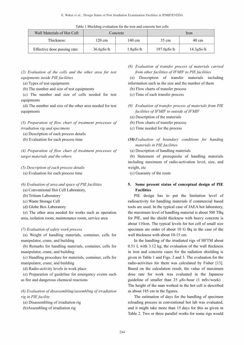
radioactivity for handling materials if commercial based tools are used. In the typical case of JAEA hot laboratory, the maximum level of handling material is about 500 TBq for PIE, and the shield thickness with heavy concrete is about 110cm. The typical levels for hot cell of small size specimen are order of about 10 G Bq in the case of the wall thickness with about 10-15 cm.
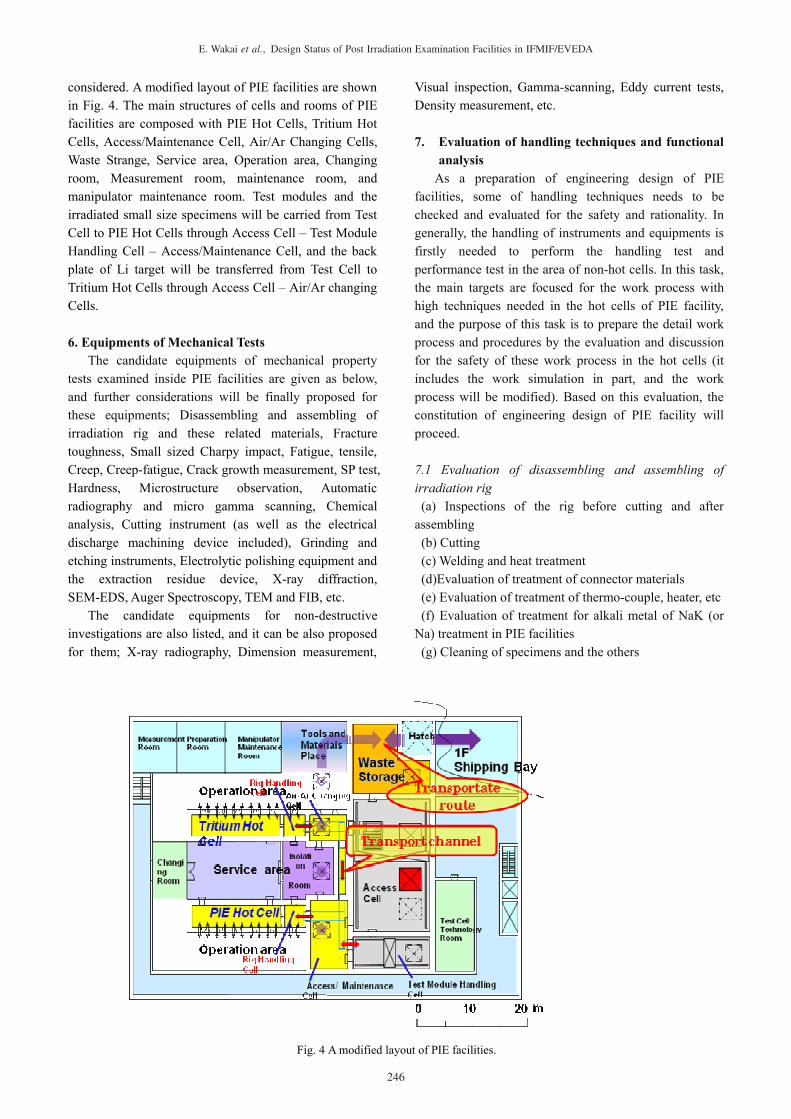
In the handling of the irradiated rigs of HFTM about 0.51 L with 3.12 kg, the evaluation of the wall thickness in iron and concrete cases for the radiation shielding is given in Table 1 and Figs. 2 and 3. The evaluation for the radio-activities for them was calculated by Fisher [13]. Based on the calculation result, the value of maximum dose rate for work was evaluated in the Japanese guideline of smaller than 25 μSv/hour (1 mSv/week) . The height of the man worked in the hot cell is described as about 185 cm in the figures.
The estimation of days for the handling of specimen reloading process in conventional hot lab was evaluated, and it might take more than 15 days for this as given in Table 2. Two or three parallel works for some rigs would
Table 1 Shielding evaluation for the iron and concrete hot cells
Wall Materials of Hot Cell: Concrete Iron
Thickness: 120 cm 140 cm 35 cm 40 cm
Effective dose passing rate: 36.6μSv/h 1.8μSv/h 197.0μSv/h 14.3μSv/h
244
E. Wakai et al., Design Status of Post Irradiation Examination Facilities in IFMIF/EVEDA

be required to perform in shorter period. The post-irradiation examination facility (PIE) with
task, the appropriate correction for the former design was examined. As a result, the equipment carrying route from outside the IFMIF building to inside the PIE area not being guaranteed was ascertained. Because of this, the equipment carrying out entrance route during 2nd floor PIE facilitating and 1st floor shipping areas was guaranteed by providing third floor crane space in portion inside the PIE area. Together, providing the crane space on hot cell top, equipment carrying out entrance from the hot cell upper hatch you proposed possible correction. With examination of the flow of the lighting sample
inside the hot cell, independence of job was guaranteed so far by adding the tunnel for sample conveyance anew from the fact that competes with the job in the access cell on only the route by way of the access cell and the like in movement of the sample between the tritium hot laboratory and the PIE hot laboratory. In inside the hot cell area, it did the area division in regard to radiation management of the operation area and the service area and line separation ventilation air conditioning equipment. Especially, there is the enlargement preventive measure of the pollution by the radioactive substance when job by providing the isolation room in one for maintenance inside the hot cell it
Fig. 2 Schematic images of iron hot cell Fig.3 Schematic images of concrete hot cell
Table 2 Estimation of days for the handling of specimen reloading process in conventional hot lab Work Process of handling of reloading process Estimated Minimum Process Time
1. Rig Inspection by X-ray t = 0.5 day
2. Cutting process of rig’s edge in order to pick up specimens and remove NaK or Na (including the cleaning of NaK or Na)
t > 3 days
3. Observation and checking ID of specimen t > 2 days
4. Measurement of size of specimens t > 3 days
5. Insert process of specimens, thermo-couples, fluence monitor, NaK, etc into a new rig
t > 3 days
6. Welding and reheating process of Rig t > 1 day
7. Checking the configuration of specimens inside the rig by X-ray t = 0.5 day
1-7: Total Work Process t > 15 days
245
E. Wakai et al., Design Status of Post Irradiation Examination Facilities in IFMIF/EVEDA
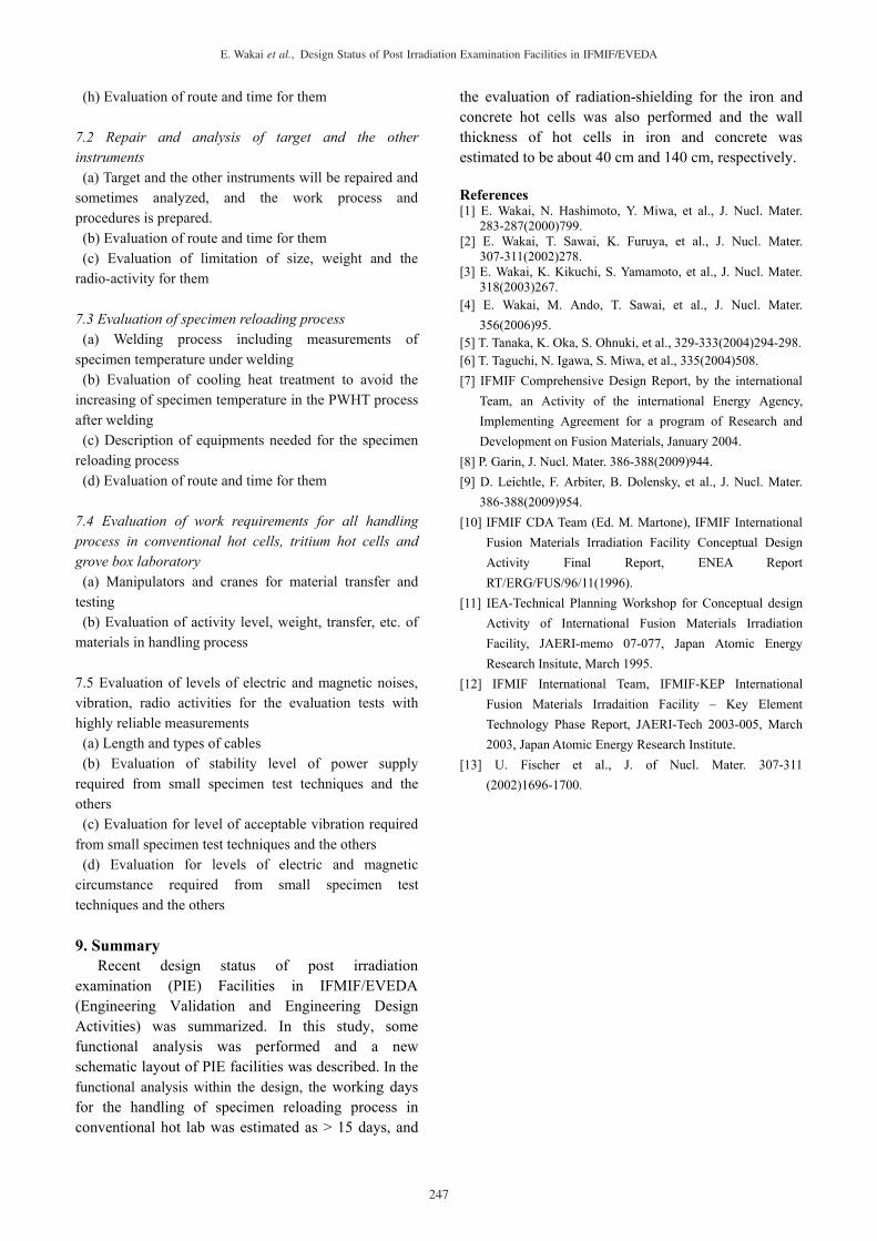
considered. A modified layout of PIE facilities are shown in Fig. 4. The main structures of cells and rooms of PIE facilities are composed with PIE Hot Cells, Tritium Hot Cells, Access/Maintenance Cell, Air/Ar Changing Cells, Waste Strange, Service area, Operation area, Changing room, Measurement room, maintenance room, and manipulator maintenance room. Test modules and the irradiated small size specimens will be carried from Test Cell to PIE Hot Cells through Access Cell – Test Module Handling Cell – Access/Maintenance Cell, and the back plate of Li target will be transferred from Test Cell to Tritium Hot Cells through Access Cell – Air/Ar changing Cells. 6. Equipments of Mechanical Tests
The candidate equipments of mechanical property tests examined inside PIE facilities are given as below, and further considerations will be finally proposed for these equipments; Disassembling and assembling of irradiation rig and these related materials, Fracture toughness, Small sized Charpy impact, Fatigue, tensile, Creep, Creep-fatigue, Crack growth measurement, SP test, Hardness, Microstructure observation, Automatic radiography and micro gamma scanning, Chemical analysis, Cutting instrument (as well as the electrical discharge machining device included), Grinding and etching instruments, Electrolytic polishing equipment and the extraction residue device, X-ray diffraction, SEM-EDS, Auger Spectroscopy, TEM and FIB, etc.
The candidate equipments for non-destructive investigations are also listed, and it can be also proposed for them; X-ray radiography, Dimension measurement,
Visual inspection, Gamma-scanning, Eddy current tests, Density measurement, etc.
7. Evaluation of handling techniques and functional
analysis As a preparation of engineering design of PIE
facilities, some of handling techniques needs to be checked and evaluated for the safety and rationality. In generally, the handling of instruments and equipments is firstly needed to perform the handling test and performance test in the area of non-hot cells. In this task, the main targets are focused for the work process with high techniques needed in the hot cells of PIE facility, and the purpose of this task is to prepare the detail work process and procedures by the evaluation and discussion for the safety of these work process in the hot cells (it includes the work simulation in part, and the work process will be modified). Based on this evaluation, the constitution of engineering design of PIE facility will proceed. 7.1 Evaluation of disassembling and assembling of irradiation rig (a) Inspections of the rig before cutting and after
assembling (b) Cutting (c) Welding and heat treatment (d)Evaluation of treatment of connector materials (e) Evaluation of treatment of thermo-couple, heater, etc (f) Evaluation of treatment for alkali metal of NaK (or
Na) treatment in PIE facilities (g) Cleaning of specimens and the others
Fig. 4 A modified layout of PIE facilities.
246
E. Wakai et al., Design Status of Post Irradiation Examination Facilities in IFMIF/EVEDA
(h) Evaluation of route and time for them
7.2 Repair and analysis of target and the other instruments (a) Target and the other instruments will be repaired and
sometimes analyzed, and the work process and procedures is prepared. (b) Evaluation of route and time for them (c) Evaluation of limitation of size, weight and the
radio-activity for them
7.3 Evaluation of specimen reloading process(a) Welding process including measurements of
specimen temperature under welding (b) Evaluation of cooling heat treatment to avoid the
increasing of specimen temperature in the PWHT process after welding (c) Description of equipments needed for the specimen
reloading process (d) Evaluation of route and time for them
7.4 Evaluation of work requirements for all handling process in conventional hot cells, tritium hot cells and grove box laboratory (a) Manipulators and cranes for material transfer and
testing (b) Evaluation of activity level, weight, transfer, etc. of
materials in handling process
7.5 Evaluation of levels of electric and magnetic noises, vibration, radio activities for the evaluation tests with highly reliable measurements (a) Length and types of cables (b) Evaluation of stability level of power supply
required from small specimen test techniques and the others (c) Evaluation for level of acceptable vibration required
from small specimen test techniques and the others (d) Evaluation for levels of electric and magnetic
circumstance required from small specimen test techniques and the others
9. SummaryRecent design status of post irradiation
examination (PIE) Facilities in IFMIF/EVEDA (Engineering Validation and Engineering Design Activities) was summarized. In this study, some functional analysis was performed and a new schematic layout of PIE facilities was described. In the functional analysis within the design, the working days for the handling of specimen reloading process in conventional hot lab was estimated as > 15 days, and
the evaluation of radiation-shielding for the iron and concrete hot cells was also performed and the wall thickness of hot cells in iron and concrete was estimated to be about 40 cm and 140 cm, respectively.
References [1] E. Wakai, N. Hashimoto, Y. Miwa, et al., J. Nucl. Mater.
283-287(2000)799.[2] E. Wakai, T. Sawai, K. Furuya, et al., J. Nucl. Mater.
307-311(2002)278. [3] E. Wakai, K. Kikuchi, S. Yamamoto, et al., J. Nucl. Mater.
318(2003)267.[4] E. Wakai, M. Ando, T. Sawai, et al., J. Nucl. Mater.
356(2006)95.[5] T. Tanaka, K. Oka, S. Ohnuki, et al., 329-333(2004)294-298. [6] T. Taguchi, N. Igawa, S. Miwa, et al., 335(2004)508. [7] IFMIF Comprehensive Design Report, by the international
Team, an Activity of the international Energy Agency, Implementing Agreement for a program of Research and Development on Fusion Materials, January 2004.
[8] P. Garin, J. Nucl. Mater. 386-388(2009)944. [9] D. Leichtle, F. Arbiter, B. Dolensky, et al., J. Nucl. Mater.
386-388(2009)954.[10] IFMIF CDA Team (Ed. M. Martone), IFMIF International
Fusion Materials Irradiation Facility Conceptual Design Activity Final Report, ENEA Report RT/ERG/FUS/96/11(1996).
[11] IEA-Technical Planning Workshop for Conceptual design Activity of International Fusion Materials Irradiation Facility, JAERI-memo 07-077, Japan Atomic Energy Research Insitute, March 1995.
[12] IFMIF International Team, IFMIF-KEP International Fusion Materials Irradaition Facility – Key Element Technology Phase Report, JAERI-Tech 2003-005, March 2003, Japan Atomic Energy Research Institute.
[13] U. Fischer et al., J. of Nucl. Mater. 307-311 (2002)1696-1700.
247
E. Wakai et al., Design Status of Post Irradiation Examination Facilities in IFMIF/EVEDA