design standards manual (00118165.docx;1)
TRANSCRIPT

Design Standards Manual
JULY 2020
Adopted by Resolution 20-25 on July 21, 2020

i

1
TABLE OF CONTENTS INTRODUCTION ............................................................................................................................. 1-1
1.1 PURPOSE ............................................................................................................................................. 1-1 1.2 GENERAL INFORMATION ......................................................................................................................... 1-1 1.3 DESIGN AND CONSTRUCTION ................................................................................................................... 1-1 1.4 CONSTRUCTION PERMITS ........................................................................................................................ 1-2 1.5 ADDITIONAL INFORMATION AND RESOURCES .............................................................................................. 1-2 1.6 VARIANCE PROCESS ............................................................................................................................... 1-3 1.7 STREET IMPROVEMENT POLICY ................................................................................................................. 1-3 1.8 STORM DRAIN POLICY ............................................................................................................................ 1-4 1.9 DEVELOPMENT POLICY ........................................................................................................................... 1-4 1.10 LAND DIVISIONS .................................................................................................................................... 1-4 1.11 DEFINITIONS AND ABBREVIATIONS ............................................................................................................ 1-5
SURVEYING STANDARDS .................................................................................................................. 2-1
2.1 MONUMENTS ....................................................................................................................................... 2-1 2.2 IRON PINS ............................................................................................................................................ 2-1 2.3 VERTICAL CONTROL REQUIREMENTS.......................................................................................................... 2-1 2.4 EXISTING TOPOGRAPHY .......................................................................................................................... 2-1
GRADING AND DRAINAGE................................................................................................................ 3-1
3.1 SOILS REPORT REQUIREMENTS ................................................................................................................. 3-1 3.2 DRAINAGE ............................................................................................................................................ 3-2 3.3 PERIMETER STREETS ............................................................................................................................... 3-4 3.4 LOW WATER CROSSINGS ......................................................................................................................... 3-4 3.5 STREET FLOW ....................................................................................................................................... 3-5 3.6 SCUPPERS AND SPILLWAYS....................................................................................................................... 3-5 3.7 RETENTION BASINS ................................................................................................................................ 3-6 3.8 DRYWELLS ............................................................................................................................................ 3-7 3.9 UNDERGROUND STORAGE ....................................................................................................................... 3-7 3.10 STORM DRAINS ..................................................................................................................................... 3-9 3.11 USE OF EQUALIZATION PIPES ................................................................................................................... 3-9 3.12 CUSTOM, SINGLE, OR INDIVIDUAL LARGE LOTS .......................................................................................... 3-10 3.13 GRADING AND DRAINAGE PLAN REQUIREMENTS ........................................................................................ 3-10
ROADS AND STREETS ...................................................................................................................... 4-1
4.1 STANDARD SPECIFICATIONS FOR CONSTRUCTION ......................................................................................... 4-1 4.2 STANDARD DESIGN DETAILS..................................................................................................................... 4-1 4.3 STREET DESIGN ..................................................................................................................................... 4-1 4.4 STREET CLASSIFICATION IN APPLICATION .................................................................................................... 4-9 4.5 ATYPICAL STREET SECTIONS ................................................................................................................... 4-10 4.6 RESERVED ....................................................................................................................................... 4-11 4.7 STREET NAMING GUIDELINES ................................................................................................................. 4-11 4.8 RIGHT-OF-WAY (ROW) REQUIREMENTS ................................................................................................. 4-11 4.9 PUBLIC UTILITY EASEMENTS (PUE) ......................................................................................................... 4-12 4.10 HORIZONTAL ALIGNMENT ..................................................................................................................... 4-12 4.11 VERTICAL ALIGNMENT .......................................................................................................................... 4-12 4.12 CURB RETURNS ................................................................................................................................... 4-12
2
4.13 SIDEWALK RAMPS ................................................................................................................................ 4-13 4.14 PEDESTRIAN REFUGES, MIDBLOCK CROSSINGS, AND INTERSECTIONS ............................................................. 4-14 4.15 DETECTABLE WARNING SURFACE ............................................................................................................ 4-14 4.16 INTERSECTION STANDARDS .................................................................................................................... 4-15 4.17 VALLEY GUTTERS ................................................................................................................................. 4-16 4.18 TRAFFIC CALMING ............................................................................................................................... 4-17 4.19 PAVEMENT STRUCTURAL DESIGN STANDARDS ........................................................................................... 4-17 4.20 ACCESS DRIVES INTO PRIVATE DEVELOPMENTS .......................................................................................... 4-19 4.21 TRANSIT INFRASTRUCTURE .................................................................................................................... 4-23 4.22 SURVEY MONUMENTS .......................................................................................................................... 4-24 4.23 PARTIAL AND HALF-STREET STANDARDS ................................................................................................... 4-24 4.24 PRIVATE STREETS ................................................................................................................................. 4-25 4.25 STREET LIGHT DESIGN .......................................................................................................................... 4-25 4.26 TRAFFIC SIGNALS, SIGNING AND STRIPING STANDARDS ............................................................................... 4-25 4.27 ALLEYS .............................................................................................................................................. 4-30
TRAFFIC IMPACT ANALYSIS ............................................................................................................... 5-1
5.1 PURPOSE ............................................................................................................................................. 5-1 5.2 REQUIREMENTS ..................................................................................................................................... 5-1 5.3 FINAL TRAFFIC REPORT ........................................................................................................................... 5-2
UTILITY REQUIREMENTS .................................................................................................................. 6-1
6.1 UTILITIES OVERVIEW .............................................................................................................................. 6-1 6.2 WATER SYSTEM .................................................................................................................................... 6-1 6.3 WATER DISTRIBUTION SYSTEM ................................................................................................................. 6-2 6.4 SEWER COLLECTION SYSTEM .................................................................................................................... 6-3 6.5 RAW OR RECLAIMED WATER DISTRIBUTION ................................................................................................ 6-4 6.6 TYPICAL STREET SECTION DETAILS ............................................................................................................. 6-4 6.7 WATER AND SEWER DESIGN REPORT REQUIREMENT .................................................................................... 6-5 6.8 WATER AND SEWER CONSTRUCTION DETAIL PLANS ..................................................................................... 6-5 6.9 DRY UTILITIES ....................................................................................................................................... 6-6
LANDSCAPE STANDARDS .................................................................................................................. 7-1
7.1 APPLICABILITY ....................................................................................................................................... 7-1 7.2 DEFINITIONS ......................................................................................................................................... 7-1 7.3 LANDSCAPE DESIGN PLAN ....................................................................................................................... 7-1 7.4 LANDSCAPE DESIGN GUIDELINES .............................................................................................................. 7-2 7.5 LANDSCAPING REQUIREMENTS ................................................................................................................. 7-3 7.6 REFERENCE DOCUMENTS ........................................................................................................................ 7-3
LIGHT STANDARDS ......................................................................................................................... 8-1
8.1 GENERAL POLICY ................................................................................................................................... 8-1 8.2 DEFINITIONS ......................................................................................................................................... 8-1 8.3 STREETLIGHT DESIGN AND LOCATIONS ....................................................................................................... 8-2 8.4 PRIVATE RESPONSIBILITIES ....................................................................................................................... 8-2 8.5 PRIVATE UTILITY COORDINATION .............................................................................................................. 8-3
SMALL WIRELESS FACILITIES ............................................................................................................. 9-1
9.1 INTRODUCTION ..................................................................................................................................... 9-1 9.2 GENERAL INFORMATION ......................................................................................................................... 9-1 9.3 DEFINITIONS ......................................................................................................................................... 9-2

3
9.4 FEES & CHARGES ................................................................................................................................... 9-3 9.5 LOCATIONS ........................................................................................................................................... 9-3 9.6 UTILITY PERMIT PROCESS-OVERVIEW ........................................................................................................ 9-4 9.7 PERMIT PROCESS – DENIAL OR INCOMPLETE APPLICATIONS ........................................................................... 9-4 9.8 VARIANCE PROCESS ............................................................................................................................... 9-5 9.9 SUBMITTAL REQUIREMENTS ..................................................................................................................... 9-5 9.10 DESIGN GUIDELINES ............................................................................................................................... 9-7 9.11 ANTENNAS AND RRH/RRU ..................................................................................................................... 9-7 9.12 GROUND EQUIPMENT (CABINETS, METERS, AND MISC. EQUIPMENT) .............................................................. 9-9 9.13 UTILITY POLE DESIGN - STREETLIGHTS...................................................................................................... 9-10 9.14 UTILITY POLE DESIGN – TRAFFIC SIGNALS ................................................................................................. 9-11 9.15 WIRELESS SUPPORT STRUCTURES – ITS MONOPOLES ................................................................................. 9-13 9.16 WIRELESS SUPPORT STRUCTURES – MONOPOLE (CARRIER OWNED) ............................................................. 9-13 9.17 SITE AND CONSTRUCTION DRAWINGS PLAN REQUIREMENTS ........................................................................ 9-14 9.18 RADIO FREQUENCY .............................................................................................................................. 9-17 9.19 CONSTRUCTION REQUIREMENTS ............................................................................................................. 9-17
STANDARD DRAWING INDEX .......................................................................................................... 10-1
10.1 STANDARD PLANS AND ROADWAY DETAILS INDEX (SEE APPENDIX B) ............................................................ 10-1 10.2 FIRE DEPARTMENT DETAILS INDEX (SEE APPENDIX H) ................................................................................. 10-2 10.3 SMALL WIRELESS FACILITY DETAILS INDEX (SEE APPENDIX J) ........................................................................ 10-2

4
TABLES AND FIGURES Table 4.3.1 – Minimum ROW Width Table 4.3.2 – Minimum Street Structural Section and Fiber Alternative Table 4.3.3 – Minimum Road Design Standards Table 4.3.4 – Roadway Design Guidelines Table 4.3.5 – Access Management Guidelines Table 4.20.1 – Driveway Separation by Street Type from Intersections Figure 4.20.1 – Driveway Separation by Street Type Table 4.20.2 – Driveway Dimensions Figure 4.20.2 – Shared-Use Paths Crossing Access Drives Table 7.5.1 – ROW Landscape Standards Figure 8.2.1 – Light Terminology
APPENDIX
A. Standard Plan Notes
B. Standard Plans and Roadway Details
C. Plan Submittal Checklists and Guidelines
D. SWPPP Guidance Checklist
E. Amendments to the IFC 2012
F. Fire Department Requirements and Information
G. Fire Flow Requirements
H. Fire Department Details
I. Global Water Resources Code of Practice
J. Small Wireless Facilities Details
K. MS4 Requirements
L. Street Name Change Policy
M. MCDOT Temporary Traffic Control; Devices and Applications
N. MCDOT Pavement Marking Manual
O. Typical Traffic Signal Equipment Placement
P. Landscaping Requirement
Q. Roundabouts
R. Approved Product List
S. Arizona Parkway Design Guide Recommendations (prepared for MCDOT)

City of Maricopa – Design Standards Manual - July 2020 Introduction 1-1
INTRODUCTION
1.1 PURPOSE
A. The purpose of this Design Standards Manual is to provide developers/applicants and their designers with a minimum set of the design requirements to guide them with development of public and private infrastructure within the City of Maricopa and to provide for the health, safety, and welfare of the citizens and visitors of the City. Design concepts and specific technical data are outlined in this manual but are not intended to supersede sound engineering judgment. All plans are to be prepared with these concepts in mind and will be reviewed accordingly.
B. This manual is divided into individual parts which cover specific elements of the design review process. This manual begins with general information followed by specific technical details. Updates will be published and made available periodically. Pending updates, new standards, forms, checklists, and exhibits are available on the City of Maricopa website.
1.2 GENERAL INFORMATION
Development within the City shall comply with requirements of these design standards in conjunction with the Subdivision Ordinance and Zoning Code, and the rules and regulations of other applicable regulatory agencies that have jurisdiction within the City of Maricopa. Copies of these documents, with revisions, are on file in the Office of the Clerk of the City of Maricopa. Preliminary and final design plans shall be prepared in accordance with these standards unless using expressly approved alternatives or equivalencies by the City of Maricopa.
1.3 DESIGN AND CONSTRUCTION
A. All design methods and standards shall be in accordance with: 1. The signed, sealed and approved plans. 2. The City of Maricopa Design Standards Manual (DSM) 3. The Uniform Standard Specifications and Details for Public Works Construction published
through the Maricopa Association of Governments (MAG STD DTLS and MAG STD SPEC) 4. American Association of State Highway and Transportation Officials (AASHTO) Guidelines 5. The Manual on Uniform Traffic Control Devices for Streets and Highways (MUTCD) 6. The Pinal County Drainage Manual Volumes 1 and 2 (PCDM)
a. Adapting design standards to benefit the contexts of community design may reference guidance from industry leading guides on efficient development (i.e. LEED-ND, Low-Impact Development Stormwater Management, etc.)
B. Site improvements and building construction shall be in accordance with: 1. Design details contained within the Design Standards Manual. 2. The Subdivision Ordinance and/or Zoning Code of the City of Maricopa. 3. The Uniform Standard Specifications and Details for Public Works Construction published
through the Maricopa Association of Governments (MAG STD DTL and MAG STD SPECS). 4. The Pinal County Drainage Manual Volumes 1 and 2 (PCDM). 5. The current and pertinent International Code Council (ICC) regulations, as adopted by the
City of Maricopa. 6. Other standards may be approved on a case-by-case basis.

City of Maricopa – Design Standards Manual - July 2020 Introduction 1-2
1.4 CONSTRUCTION PERMITS
Construction permits are required for all construction, residential and non-residential, within the City of Maricopa.
1.5 ADDITIONAL INFORMATION AND RESOURCES
A. Utilities. The City of Maricopa does not provide any utility service. 1. The applicant has the responsibility to submit and obtain approval from any involved utility
providers and other outside agencies. 2. The applicant shall obtain approvals from the appropriate utility providers, other outside
agencies and provide copies to the City of Maricopa showing approval.
B. Septic Systems. 1. Installation of a new septic system requires prior approval of the City Engineer, and will only
be granted when adequate sewer service is not available. 2. Installation or abandonment of an on-site wastewater treatment facility, including a
conventional septic tank system, requires registration with Pinal County Community Development. Pinal County shall be responsible for the review and approval of all septic systems and required permits including notice of intent to discharge, discharge authorization, and setback certifications. Information can be obtained online or in person at: Pinal County Government Aquifer Protection 31 N Pinal Street Florence, AZ 85132 520.509.3555 (local) or 888.431.1311 (toll Free)
C. Fire Prevention. Submittals to the City are distributed to Fire Prevention for review; separate submittals to the Fire Department are not required. For the Fire Plan Review Guidelines and the Fire Flow Requirements refer to Appendix G.
D. Flood Control. Pinal County Flood Control District (PCFCD) reviews drainage reports and improvement plans for commercial and subdivision developments located wholly or in part within a Federal Emergency Management Agency (FEMA) 100-year flood zone. Pinal County Flood Control District approval is required prior to the City of Maricopa approval. Reviews can occur concurrently between the two agencies.
E. Dust Control. Pinal County Air Quality Control District reviews earthmoving activity such as land stripping, earthmoving, blasting, trenching, road construction, grading, landscaping, stockpiling excavated materials, storing excavated materials, loading excavated materials, clearing and grubbing, or any activity associated with land development which results in a disturbed surface area of dust generating operations equal to or greater than 0.1 acres. These activities require dust registration with Pinal County Air Quality.
F. Public Health/Water Pollution. Arizona Department of Environmental Quality (ADEQ): The applicant shall be responsible for conformance with ADEQ regulations and requirements for submittals, approvals, and notifications (i.e. sewer and water line construction and extensions, septic systems, Storm Water Pollution Prevention Plans, etc.).

City of Maricopa – Design Standards Manual - July 2020 Introduction 1-3
G. City of Maricopa Website and City Code: for additional information on the latest versions of the guidelines.
1.6 VARIANCE PROCESS
The City Engineer may administratively approve a variance to the Engineering Design Standards within the strict administrative authority of the City Engineer. The variance process shall not be used to eliminate or reduce safety requirements. Furthermore, a variance cannot be granted unless evidence is presented that satisfies the conditions below.
A. The variance questionnaire must be answered prior to the acceptance of an application: 1. Describe the unique conditions and circumstances (including size, shape, topography,
locations or surroundings) which are peculiar to the land, structure or building which are not applicable to other lands, structures, or buildings in the same location.
2. Describe how the alleged hardships caused by the literal interpretation of the provisions of the Engineering Standards include more than personal inconvenience and financial hardship and that the alleged hardships were not created or self-imposed.
3. Indicate why granting the variance will not interfere with or inure the rights of other properties in the same location.
4. Indicate the redevelopment conditions and the improved conditions for project proposals in special character areas.
B. Include the applicable submittal documents that support the variance request, submitted with permit application.
C. Variances shall not be applied to standards outside the City Engineers authority, such as air quality standards, private utility regulations, etc.
1.7 STREET IMPROVEMENT POLICY
A. All developments within the City of Maricopa shall provide an adequate interior street and circulation system to ensure that all parcels and/or facilities within the development shall have reasonable access to the public street system. Further they shall provide access into the development for public service and/or emergency operation. Access requirements are prescribed in the Subdivision Ordinance, Section 14-6-6.
B. All streets, both public and private, shall comply with this Manual.
C. For new development, the street system shall be designed in conformance with the roadway functional classification plan per the current Transportation Master Plan and Access Management Guidelines.
D. The City accepts that adaptations may be warranted for entitlements with an emphasis on highly walkable, compact development design.
E. When new development occurs adjacent to the ROW of an existing and/or planned arterial or collector street, it is the applicant’s responsibility to install half-street improvements along the property frontage to the ultimate grade, structural section, and alignment for the said adjacent street. This may include, but not be limited to, removal and replacement of the existing street surface to the centerline if the existing structure is inadequate to meet the current design standards. Applicant must install full street improvements for all local streets; half-street

City of Maricopa – Design Standards Manual - July 2020 Introduction 1-4
construction improvements will not be permitted on local streets. A minimum pavement width of 28 feet will be required to accommodate two-way traffic.
F. For additional half-street standards, see 4.22 Survey Monuments.
1.8 STORM DRAIN POLICY
A. All hydrology and drainage requirements, procedures, and methodology shall comply with the requirements of the current Pinal County Drainage Manual (PCDM), or its subsequent revisions and/or updates. Reference should be made to the appropriate sections within the balance of these standards for specific details.
B. All developments within the City of Maricopa shall provide sufficient retention to minimize the adverse impact of such development on neighboring properties. All developments shall provide sufficient retention on-site to contain the runoff in accordance with the PCDM.
C. All new development shall provide adequate drainage facilities in order to convey runoff, generated both onsite and offsite of the project, around or through the project in such a manner as to ensure that the structures will be free from flooding and that there is at least one all-weather access for emergency and public service vehicles. The applicant shall install storm drainpipes, channels and/or other physical improvements necessary to achieve this result.
D. All development shall comply with the National Pollution Discharge Elimination System (NPDES) storm water requirements for construction sites. A Storm Water Pollution Prevention Plan (SWPPP) must be submitted with the improvement plans for review and approval to the Arizona Department of Environmental Quality (ADEQ).
1.9 DEVELOPMENT POLICY
A. All development within the City of Maricopa shall be designed and constructed in such a manner as to provide for the health, safety, and welfare for the current and future citizens of the City of Maricopa. The appropriate standards that have been established for site development include: 1. Public and/or private access for general and special uses 2. Private water and sewer systems 3. On-site and off-site drainage 4. Landscaping 5. Storm retention 6. Street lighting 7. Public utilities as may be required 8. Environmental assessment
a. Phase 1 Environmental Report requirements are listed in the Subdivision Ordinance
1.10 LAND DIVISIONS
All master planned communities, subdivision plats, minor land divisions, multi-family developments, lot line adjustments, lot splits and amended plats are processed, reviewed and approved by the City of Maricopa. The main purpose of these processes is to accomplish the land division and associated dedications necessary for orderly development enabling parcels, lots, ROW, easements, tracts and other pertinent areas to be dedicated to the City of Maricopa or the Homeowners’/Property Owners’ Association as graphically depicted on recorded plats. These plats convey many types of rights, responsibilities and conditions and become part of the public record through recordation in the Pinal

City of Maricopa – Design Standards Manual - July 2020 Introduction 1-5
County Recorder’s office. Standard public improvements such as streets and utility easements may be required for each land division. Refer to the Subdivision Ordinance Article 14 for additional information.
1.11 DEFINITIONS AND ABBREVIATIONS
The words, abbreviations, or phrases used in these standards may be found in the Maricopa Association of Governments Standard Details (MAG STD DTLS) and Maricopa Association of Governments Standard Specifications (MAG STD SPECS).

City of Maricopa – Design Standards Manual - July 2020 Surveying Standards 2-1
SURVEYING STANDARDS
2.1 MONUMENTS
Permanent survey monuments shall be installed by an Arizona Registered Land Surveyor along the easement and right-of-way lines including, but not limited to, drainage easements, and in accordance with current City standards at all corners, angle points, and points of curve and in the center at all street intersections.
2.2 IRON PINS
Iron pins shall be set at all lot corners, angle points and points of curve for each lot within the subdivision within one year of final plat approval and before the issuance of the first building permit. Permanent brass cap(s) in concrete monuments shall be set for all subdivision points that are in the public rights of way. These are to be placed in accordance with the applicable MAG standard.
2.3 VERTICAL CONTROL REQUIREMENTS
A. The vertical control for all development engineering design and construction shall be based on the vertical control established by the National Geodetic Survey (NGS) Vertical Datum. All vertical control for new development shall be on North American Vertical Datum (NAVD) 88 Datum.
B. The complete information for all National Geodetic Survey Benchmarks of Maricopa area can be found on the NGS website: www.ngs.noaa.gov. These are the only benchmarks that are currently accepted for use within the City of Maricopa limits.
2.4 EXISTING TOPOGRAPHY
The existing topography for a development shall be based on accepted City of Maricopa benchmarks and either by topographical survey or by aerial photogrammetric methods. The use of United States Geological Survey (USGS) 7.5 Minute Quadrangle Mapping for illustrating the existing topography for grading plans or for drainage studies is not acceptable.
City of Maricopa – Design Standards Manual - July 2020 Grading and Drainage 3-1
GRADING AND DRAINAGE
3.1 SOILS REPORT REQUIREMENTS
Geotechnical Report - A geotechnical/soils report shall be submitted as part of the Preliminary Plat Application or Development Review Permit. The Soils Report shall be prepared by a professional engineer with expertise in geotechnical engineering and licensed in the State of Arizona.
A. The geotechnical report shall include but is not limited to test records, results, evaluations and recommendations consisting of the following items as applicable: 1. Identifies any special geotechnical hazards, and develops recommendations regarding the
hazards, grading, foundations and pavement. 2. The geotechnical hazards portion shall consider, at a minimum, the following items:
expansive soils, soil creep, land sliding, groundwater, sulfites, and other corrosive elements. 3. The grading and foundations portion of the report shall include data regarding the
distribution and engineering characteristics of the various soil materials; data about groundwater levels; percolation test; an opinion regarding the geotechnical feasibility of the development as planned; recommendations about any needed mitigation measures for geotechnical hazards, grading criteria and foundation design criteria and any other pertinent information.
4. The pavement design portion shall include data regarding the characteristics of various subgrade materials, including aggregate base, asphaltic course, Portland cement concrete, etc. The design procedure and all assumptions used to determine the pavement section shall be presented. The selected design procedure, per the traffic and/or geotechnical report, shall not result in a lesser pavement section than the minimum stipulated in this Manual.
5. The plat soils report must reflect current plat layout, conditions, and location of lots. 6. Soil borings or test pits must be adequately spaced so, as in the opinion of the engineer of
record, the report reflects soil conditions consistent with “building” development and not necessarily just utility or roadway development.
7. Each individual lot must be identified in the report. 8. There must be field reports prepared by the geotechnical engineering firm of record noting
onsite grading operations (including structural fill placement observation and testing) in accordance with soil report recommendations.
9. A final acceptance letter or soils report addendum must be provided with each building permit application from the soils engineer of record accepting the work as installed and in conformance with the soils report recommendations. The final acceptance letter requires the individual lot to be identified in the letter as noted above in this subsection.
10. It is required that the soils report identify the plans that are being reviewed in coordination with the soils report. The report must describe the structures, expected cuts and fills and associated retaining walls, as needed, and their locations on site. All soils reports must be project specific unless otherwise accepted by the City Engineer.
11. Plot plan showing the location of all test borings or excavations. 12. Results of sub-surface field investigation. 13. Elevation of the water table (and groundwater seepage) if encountered. 14. Results of slope stability analysis (required on all sloped lots). 15. Expected total differential settlement. 16. Engineering recommendations.

City of Maricopa – Design Standards Manual - July 2020 Grading and Drainage 3-2
17. Recommendations for foundation and/or retaining wall/basement wall design and drainage. 18. Piling requirements. 19. Recommendations for slabs. 20. Soil bearing value. 21. Active fluid pressure. 22. Specification of the friction coefficient. 23. Fill material (specify compaction requirements, keying or benching, maximum fill lifts and
field testing). 24. Potential for liquefaction and seismic design. 25. Special inspection requirements for earthwork, including foundations, prior to foundation
inspection. 26. Construction sequencing plan to minimize risk of destabilizing the cut slopes or hillside
(required on sloped lots). 27. Oversized particles. 28. Field report boring logs. 29. Review of construction drawings. 30. When proposing underground storage of stormwater, see 3.9 Underground Storage.
3.2 DRAINAGE
A. All hydrology and drainage requirements, procedures, and methodology shall comply with the requirements of the current Pinal County Drainage Manual (PCDM), or its subsequent revisions and/or updates. Reference should be made to the appropriate sections within the balance of these standards for specific details.
B. Proper and adequate provisions shall be made for disposal of stormwater; this shall apply equally to grading of private properties and to public streets. Existing major water courses shall be maintained as drainage ways. Streets may be used for drainage conveyance only.
C. Post development flows cannot exceed pre-development flows in peak runoff, volume, or velocity and may not concentrate sheet flows without downstream off-site control.
D. If drywells are necessary, they shall be spaced as far apart as possible and only fifty (50%) percent of the percolation capacity can be used in calculating the required number of drywells to be utilized. In addition, a maintenance plan shall be prepared that provides for routine inspection and maintenance requiring the approval of the City Engineer.
E. The City Engineer shall require for review and approval the submittal of a drainage report whenever development and/or grading are proposed within the City of Maricopa limits. Development shall mean any man-made change to improved or unimproved real estate, including, but not limited to, the following: buildings or other structures, mining, dredging, filling, grading, paving, excavation, or drilling. 1. A preliminary drainage report shall be submitted with the preliminary plat. 2. A final drainage report shall be submitted with the construction documents.

City of Maricopa – Design Standards Manual - July 2020 Grading and Drainage 3-3
F. Preliminary Drainage Report - A preliminary drainage report shall be submitted as part of the Preliminary Plat Application or Development Review Permit, and shall at a minimum contain the following information: 1. Delineation of the boundaries of on-site and off-site drainage areas. Information about
adjacent property, such as significant differences in elevation, walls, drainage structures, buildings with their floor elevations etc. shall be provided.
2. Identify the drainage pattern for all existing and proposed streets and building sites. Label the different critical points and where inlets/outlets are to be located.
3. Justify the runoff factor (C-factor) used in the computations. 4. Describe offsite flows from adjacent properties onto the property to be developed.
Drainage area calculated peak flows, velocity and other pertinent runoff data must be presented. If the flow is in a defined channel, the channel must be improved. Special consideration for joint use of open channels as a recreational amenity is to be given on each individual project (see Section 14-6-4 Open Space and Recreation Requirements of the Subdivision Ordinance for joint use design requirements). The runoff from areas outside the development may be realigned through the new development.
5. Indicate the retention/detention volume required and provided. 6. Indicate the method for draining basins in thirty-six (36) hours, and who is responsible for
maintenance. 7. Show location of all drainage easements.
G. Final Drainage Report - A final drainage report shall be submitted as a part of the improvement plan (or permit) submittal for all developments. The report shall be a complete report and not an addendum to the preliminary drainage report. The format shall be as previously described and include the following additional information (see “Pinal County Final Drainage Manual”): 1. Place inlets and/or scuppers wherever the flow exceeds the street capacity. The inlets
and/or scuppers are to be analyzed separately and catch basin computations shall be submitted.
2. Size the storm drains and culverts and submit design computations. 3. Final retention/detention basins calculations including 36-hour percolation, or evaporation
rates. 4. Channel flow calculations considering the impacts of landscaping and other joint use
impacts on the cross-section and Manning coefficients. 5. Adjusted calculations for pre- and post- development conditions.

City of Maricopa – Design Standards Manual - July 2020 Grading and Drainage 3-4
H. The City of Maricopa has adopted the use of the National Oceanic and Atmospheric Administration (NOAA) Atlas 14 in establishing the precipitation frequency estimates for the calculation of the required retention volumes.
I. The NOAA Atlas 14 data is based on the actual latitude and longitude of the site to be developed.
J. Point precipitation frequency estimate shall be the upper bound of the 90% confidence interval.
K. The Rational Method shall be used to estimate run-off when the drainage area is a uniform land use. For larger, more complex watersheds or drainage networks, a rainfall runoff model shall be developed.
L. Storm Water Pollution Prevention Plans (SWPPP) are required when more than one (1) acre of property is being disturbed for development. The SWPPP shall be maintained for the duration of construction or until constructed improvements alleviate the need for the SWPPP.
M. Storm water plans for subdivisions and developments which are in whole or in part within a Federal Emergency Management Agency (FEMA) 100-year flood zone shall be submitted to the Pinal County Flood Control District and approved by the Pinal County Flood Control District prior to approval by the City of Maricopa. For larger developments, Conditional Letters of Map Revision (CLOMR) and Letters of Map Revision (LOMR) may be processed per parcel affected by the flood plain, provided that the construction documents and drainage reports are also separated by corresponding parcel.
3.3 PERIMETER STREETS
Storm flows generated from the half-street of contiguous Arterial or Collector Streets must be collected and retained on-site of the adjacent parcel or site, unless a centralized storm drain system exists with adequate capacity to meet the needs of design storm flows and volumes.
3.4 LOW WATER CROSSINGS
Any crossing designed for less than the 100-year storm event shall be considered a low water crossing, and shall require approval of the City Engineer, but in no event shall such crossing pass less than the 10-year peak discharge.
A. Hydraulic Criteria: 1. Culverts shall have the capacity to carry the 10-year peak discharge as determined by the
City Engineer. 2. At no time shall the waterway section at the crossing cause a significant rise (one-foot or
more) in the 100-year water surface elevation, or cause adverse impacts to surrounding properties, or cause flows to accelerate to velocities greater than those expected during the 100-year flood.
B. For all low water crossing designed for less than the 100-year storm event, developer/applicant shall install the following safety measures to be approved by the City of Maricopa during the permitting process: 1. Access control swing gates that can be closed during storm events to prevent vehicular
crossings. Refer to Appendix B for a sample gate. 2. Paved turnaround areas that will allow drivers to change direction and leave the flooding
area safely, prior to approaching the access gates.

City of Maricopa – Design Standards Manual - July 2020 Grading and Drainage 3-5
3. Electronic signage that can be activated by City officials to warn motorists that the access gates are closed and to avoid the area.
C. General guidelines for the design and construction of low-water crossings are as follows:
1. Road Approach Grade Criteria: a. Minimum 0.5% b. Maximum 5.0%
2. Side Slopes on a low water crossing shall not be steeper than 3:1 and shall be protected by a six-inch concrete facing or by 18-inch riprap for a distance determined by the design flow.
3. Culverts must be rubber gasket reinforced concrete pipe (RGRCP) or equivalent with a minimum of 18-inch diameter. Headwalls are required for all culverts and where buoyancy protection is necessary. If high headwater depths are to be encountered, or the approach velocity in the channel will cause scour, a short channel apron or cut-off wall should be provided at the toe of the headwall.
4. Cover over the culverts will be as follows: a. Round pipe – minimum 12-inch or as recommended by the pipe manufacturer. b. Arch pipe – minimum 18-inch or as recommended by the pipe manufacturer or
minimum 12-inch if HS-10-44 loading is applied.
3.5 STREET FLOW
The Rational Method shall be used to calculate street runoff. Calculations shall be submitted which demonstrate compliance with the following criteria:
A. 10-year storm: 1. Collector streets must maintain one dry travel lane in each direction. 2. Collector streets must contain the 10-year storm event flows within the curbs (at or below
the top of curb elevations on either side of the street).
B. 100-year storm: 1. Calculated flows must be contained within the ROW limits, and flow depths shall not exceed
six (6) inches above the roadway centerline/crown. 2. Wetted perimeter length shall not exceed the distance from back of sidewalk to back of
sidewalk.
3.6 SCUPPERS AND SPILLWAYS
Street drainage or runoff shall be removed from the street through the use of a MAG STD DTL 206 scupper. The use of catch basins and storm drains will not be permitted except in situations where the use of a scupper is neither practical nor possible. These situations must be fully justified and approved by the City Engineer prior to the submittal of construction plans for review. In urbanized or character areas, catch basins and storm drains may be permitted where necessary and practical.
A. Storm water structures such as head walls, retaining walls, and scuppers which present a fall hazard of eighteen (18) inches or greater shall have safety rails installed per MAG STD DTL 145, Safety Rail.
B. The scupper spillway shall be constructed with (1) grouted riprap or (2) textured concrete with imbedded devices to prevent erosion and scouring. This textured surface is also necessary to

City of Maricopa – Design Standards Manual - July 2020 Grading and Drainage 3-6
prevent the use of the spillways for undesirable recreational activities and to discourage public access and use.
C. Scuppers must terminate into the bottom basin at least 0.50’ above the bottom basin elevation with a sediment trap.
3.7 RETENTION BASINS
Retention basins shall be designed to allow for removal of street flows and all developed storm flows for the project. Retention basins must adhere to the following criteria:
A. The retention basin must be located entirely outside of the Right-of-Way (ROW) and Public Utility Easement (PUE). No basin side slopes are permitted within the ROW or PUE.
B. Submit volume required and volume provided calculations for each basin.
C. Basin high water elevations must have a minimum of one (1) foot of freeboard measured from basin high water adjacent curb opening or scupper flow line elevation.
D. Basin Depth 1. Basins must have a maximum depth of ponding of three (3) feet. 2. Basins must have a maximum depth, measured from top of basin, of four (4) feet. 3. Additional depth may be allowed with attractive barriers and protective safety measures with
City Engineer approval.
E. Basins must drain within 36 hours of a storm event either through surface percolation or through the assistance of drywells.
F. Maximum side slopes are 4:1 (four feet horizontal to one foot vertical) with turf, soil, or ground cover installation, or 3:1 with riprap installation.
1. Retaining walls may be used if aesthetic and surfaces avoid water line makings and materials are noncorrosive. If permitted, they must be designed to avoid fall hazards.
G. The basins must retain full street flow for the street run-off for streets internal to the project, both public and private.
H. The basins must retain one-half street flow for the street run-off of the adjacent streets contiguous to the project, both public and private. NOTE: Property containing private streets must contain the drainage from the private streets within its own property boundaries.
I. Shared retention is permitted between parcels, lots, and/or tracts in developments if: 1. Plat documents note and designate cross-drainage and cross-retention easements 2. Responsibility for maintenance is recorded within covenants, conditions, and restrictions
(CCR’s) documents
J. Water, sewer, or any other utility lines are not permitted to cross beneath retention basins.
K. Cross-sections, drawn to scale both horizontally and vertically, are required of all retention basins showing the bottom basin elevation, high water elevation, and adjacent grades.
L. Each subdivision phase must be able to stand alone in the containment and retention of the storm runoff falling within the boundaries of that approved phase. If a retention or detention basin is

City of Maricopa – Design Standards Manual - July 2020 Grading and Drainage 3-7
shared between phases, the ultimate size and configuration of the storage facility must be constructed during the first phase of construction that contributes runoff to the basin.
M. When facilities such as playgrounds, ball fields, soccer fields, etc. are in retention basins, the amenities must be accessible through Americans with Disabilities Act (ADA) compliant routes. The routes must be maintained compliant by the Homeowners’ Association/Property Owners’ Association (HOA/POA) and such responsibility shall be set forth within recorded covenants, conditions and restrictions documents.
N. New site developments with roadways are required to provide temporary retention basins to store storm drainage from the roadway until the permanent retention facilities are operational. Temporary retention basins are required to store runoff only from the roadway surface; however, scuppers should be sized for the flows anticipated at completion of development.
O. Exceptions to these requirements will be considered by the City Engineer based on terrain and other conditions.
3.8 DRYWELLS
A. When drywells are anticipated, the initial infiltration rate used for design purposes shall be 0.1 cfs per drywell. All drywells designed at this flow rate shall be shown on the plans. At the time of construction, the drywell disposal rate shall be 50% of the constant head pressure test percolation rate; however, in no case will the storm water disposal rate exceed 0.5 cfs.
B. Drywells must be placed a minimum of twenty (20) feet from the inlet to the basins such as scuppers and spillways.
C. Drywell rims must be set 0.20’ above the bottom basin elevation to help prevent silting of drywell.
D. Based on the geotechnical report, recommendations may be made on the placement of drywells; drywells may need to be placed a certain distance apart based on the soil strata of the site.
E. The property owner of record has the responsibility for the performance, operation, registration, and maintenance of drywells used with onsite retention. Drywells must initially be registered with the Arizona Department of Environmental Quality (ADEQ) and a yearly maintenance record sent to ADEQ per their requirements. A tabulation showing drywell number, registration number, and percolation rate shall be located on the coversheet and completed prior to as-built submission.
F. Drywells must be a dual chamber system with an interceptor chamber and a settling chamber (Maxwell Plus or approved equal).
G. Storm drainpipes cannot be directly tied into the interceptor chamber of the drywell.
3.9 UNDERGROUND STORAGE
Underground storage in the form of large diameter pipes, tanks, and vaults is permitted for storage of onsite (private) storm water in commercial or industrial sites, and on a case-by-case basis as approved by the City Engineer.
Underground storage is not permitted for the retention of offsite (ROW) flows, unless approved by the City Engineer.

City of Maricopa – Design Standards Manual - July 2020 Grading and Drainage 3-8
The design criteria for corrugated metal pipe (CMP) used as retention are given below. Other retention systems such as tanks and vaults will be approved on a case by case basis by the City Engineer. Submit the manufacturer’s information and applicable plan sheets and calculations for review.
A. Underground retention tanks are not permitted beneath retention basins.
B. Installation of corrugated metal pipe shall be in accordance with MAG Specification 621 and a note on strutting spacing, if required, demonstrating that they are within manufacturer's specification and recommendation for installation.
C. Trenching, excavation, bedding, and backfill shall be in accordance with MAG Specification 601 and material per MAG Specification 760. Filter fabric is required below granular bedding, along trench sides, and above pipe and granular bedding to prevent surrounding soils from filling with voids and destabilizing the backfill.
D. Provide a backfill detail. Include material and compaction requirements, particularly under the haunches and to the spring line.
E. A report is required, prepared and sealed by a Professional Engineer registered in the State of Arizona, showing the depth to groundwater and the depth of the proposed installation. Provide soil boring results to at least 10-feet below the bottom of the proposed installation.
F. Soil conditions at the proposed location of the underground storage tank shall be investigated. Plans shall include the results of the soil investigation and shall provide data for the following parameters: 1. Soil (pH) 2. Resistivity (ohm-cm) 3. Chloride concentration (ppm) 4. Sulfate concentration (ppm) 5. Moisture content (%)
G. Demonstration of a minimum 75-year life of the installation (lining and coating must be specified). Methodology for determining the soil side service life of corrugated steel pipe shall be per the Soil Side Durability of Corrugated Steel Pipe, Final Report 1991, prepared for the National Corrugated Steel Pipe Association.
H. Traffic/load bearing capacity of the installation (pipe gage and corrugation size of corrugated metal pipe and D-Load for reinforced concrete pipe) must be specified.
I. A detail of how the installation will be drained into the dry well must be provided. The sedimentation chamber and drain must be lower than the tank drain so the tank drains completely.
J. Provide a minimum of two (2) access points into each tank. Forty-eight (48) inch minimum manhole shafts at each access point into the underground pipe with installed fixed ladders are required. A thirty (30) inch manhole frame and cover can be used at grade with a concrete collar where the cover is subject to wheel loads.
K. Provide assurance that the material used for the piping is suitable for the site's soil in the form of a letter from the Soils Engineer.
L. Specify watertight manufactured joints.

City of Maricopa – Design Standards Manual - July 2020 Grading and Drainage 3-9
M. Provide end walls for pipe per manufacturer(s) recommendation with a detail.
N. Cover to be a minimum of three (3) feet in traffic areas or manufacturer’s recommendation, whichever is greater.
O. Structural strength calculations, based on sub grade capacity, are required in areas subject to wheel loads.
3.10 STORM DRAINS
A. All storm water pipe installed under roadways, driveways, or other pavement subject to vehicular traffic shall be designed to withstand HS-20-wheel loading.
B. Minimum pipe sizes are twelve (12) inch diameter for laterals and fifteen (15) inch diameter for mains, where storm drains are subject to wheel loads.
C. Any piping within the ROW must be rubber gasket reinforced concrete pipe (RGRCP). Onsite storm drainpipe and pipe maintained by the Homeowners’ Association (HOA) or Property Owners’ Association (POA) can be corrugated high density polyethylene pipe (CHDPEP) or corrugated metal pipe (CMP).
D. When a storm drain must be the sole path to a retention basin from a development or site improvement, the piping must be designed to carry the 10-year, 2-hour design storm peak flow rate.
E. Storm drains should maintain a minimum six (6) foot horizontal separation clearance from other storm drains, water lines, and sewer lines, and a minimum one (1) foot vertical clearance from other storm drain and sewer lines. If the storm drain is over the water line, a minimum two (2) foot of clearance is required and the water line/storm drain crossing is to have extra protection (i.e. concrete encasement). If the storm drain is under the water line, a minimum of one (1) foot of clearance is adequate.
F. When storm drains must enter a retention basin below grade, the use of a bubbler box is required. Bubbler boxes shall be constructed on a minimum five feet of granular fill material.
3.11 USE OF EQUALIZATION PIPES
A. If equalization pipes are required to equalize the retained storm event volumes in separate retention basins within a parcel, the equalization pipes passing under a street must be at, or as close to, right angles to the street alignment as possible.
B. Any equalization pipes beneath the ROW or PUE, including those beneath pavement, must be RGRCP, unless approved by the City Engineer.
C. Equalization pipes must have an invert elevation a minimum of one (1) foot above the bottom basin elevation of the retention basin to reduce sedimentation in the equalization pipe.
D. The minimum diameter of an equalization pipe is twelve (12) inches.
E. The inlets and outlets to the equalization pipes shall include headwalls per MAG STD DTL 501 and shall include trash racks per MAG STD DTL 502 or other devices adequate to prevent access into the pipes by persons.
City of Maricopa – Design Standards Manual - July 2020 Grading and Drainage 3-10
F. Maintenance of the equalization pipes, headwalls, and trash racks shall be the responsibility of the HOA for residential subdivisions or the POA for commercial developments, as applicable.
3.12 CUSTOM, SINGLE, OR INDIVIDUAL LARGE LOTS
A. Residential lots individually developed or within a platted master planned community, that are one (1) acre or larger in size, must provide on-site retention for all development flows generated from development site improvements, including adjacent street flows.
B. When on-site retention basins are used, basins cannot exceed three (3) feet in depth and must be located only in the front yard, forward of any fence line.
C. The retention basins must be in a drainage easement.
D. The maintenance of the retention basins is the responsibility of the homeowner.
E. A final drainage report may not be required if the site is not impacted by off-site storm flows; however, all drainage and retention calculations must be included on the Grading and Drainage Plan.
F. The grading plan for the lot must include elevations on all corners (outfall included), bottom retention elevation, high water elevation, finished floor elevation, and pad elevation. Include calculations demonstrating the required and provided retention, including the adjacent half-street flows.
G. Calculations for weighted “C” coefficient must be included on the Grading and Drainage Plan.
H. A swale from the backyard to the front yard may be necessary to achieve proper grading requirements. If a swale is necessary, appropriate wall openings or wall design between the front and backyards will be necessary.
3.13 GRADING AND DRAINAGE PLAN REQUIREMENTS
Grading and Drainage Construction Plans shall be prepared in accordance with the requirements included in the Appendix – primarily Appendix C.

City of Maricopa – Design Standards Manual - July 2020 Roads and Streets 4-1
ROADS AND STREETS
4.1 STANDARD SPECIFICATIONS FOR CONSTRUCTION
All public or private street construction within the City of Maricopa shall comply with the specifications contained in the current edition of the Maricopa Association of Governments Uniform Standard Specifications and Details for Public Works Construction (“MAG STD DTL”).
4.2 STANDARD DESIGN DETAILS
A. All street design details to be used in the design of public or private streets within the City of Maricopa shall be from the current edition of the Maricopa Association of Governments Uniform Standard Specifications and Details for Public Works Construction.
B. If a MAG STD DTL must be modified to fit the street design or conditions, the use of the modified standard detail must be approved in advance by the City Engineer. The modified standard detail must be shown on the appropriate plans with modifications noted.
C. If a design detail is required for which there is no MAG STD DTL, a standard detail from ADOT, a county, or another city may be used, with prior approval by the City Engineer.
D. City of Maricopa standard design details will be applied when specified throughout this document (see Appendix B).
4.3 STREET DESIGN
A. Design of Streets shall conform to standards established by this Manual. For specifics see: Table 4.3.1 – Minimum ROW Width Table 4.3.2 – Minimum Street Structural Section and Fiber Alternative Table 4.3.3 – Minimum Road Design Standards Table 4.3.4 – Roadway Design Guidelines Table 4.3.5 – Access Management Guidelines
B. Private streets shall conform to above stated design standards unless otherwise approved by the City Engineer in advance. Private streets shall be placed within their own parcel or tract of land. Where site conditions necessitate adapted design solutions, modifications may be approved by the City Council. An adapted design solution is any solution not specifically included in MAG STD DTL or a standard detail from ADOT, a county, or another city.
C. Cul-de-sac streets shall be constructed with a minimum radius of fifty (50) feet, measured to back of curb with the expectation that no parking be allowed. The City Engineer may accept an equally convenient form of turning and backing areas where extreme conditions justify. The maximum length of Cul-de-sac streets shall be in accordance with the adopted version of the International Fire Code (IFC) as amended. Landscape islands are encouraged at the center of the cul-de-sac conducive to the turning radius for emergency services. See detail MAR-221 or MAR-222.
D. Dead-end streets will not be approved except in locations recommended to the City Engineer as necessary for future development of adjacent lands; with an unobstructed temporary fifty (50) foot radius turn-around.
E. Private Access and Driveways from private property to any dedicated street shall be constructed in accordance with permits issued by the City. Width of driveway at the property line shall be a
City of Maricopa – Design Standards Manual - July 2020 Roads and Streets 4-2
minimum of twelve (12) feet and a maximum of forty (40) feet. The width will depend on the access to be served (i.e., residential or commercial) and shall be per MAG STD DTL 250-1 or 250-2.
F. Shared-Use Paths 1. The preferred combination of pedestrian and bicycle facilities within ROW with streets have
designated speed limits of 35 MPH or higher for safety and comfort for the greatest number of users supporting multiple modes.
2. Paths are adequate in width for comfort of all users, including for diverse user preferences at 14-feet wide, including 10-feet of concrete path and 4-feet of compacted DG. Additional detail, see 4.19 Pavement Structural Design Standards.
3. Paths are separated from the curb by a landscaped parkway. 4. Paths should offer at least one-foot of clearance from the limits of ROW.
G. Bicycle Lanes 1. All arterial and collector streets shall be designed to accommodate bicycle and pedestrian
travel. Bike lanes are an alternative offered in constrained conditions for arterial streets with speed limits of 35 MPH or higher. For the safety and comfort of all users, physically separated bikeways are placed in the Share-Use Path as the standard.
2. Street classification of Arterial or larger will typically require protected bikeways in the form of shared use paths. Where bike lanes are approved, lanes shall measure six and one-half feet (6’-6”) as measured from back of curb unless otherwise noted within this Manual or specifically approved by the City Engineer and shall have a minimum four-foot (4’) width of uniform pavement.
3. Painted buffers and markings are required for bike lanes. a. Arterials with bike lanes provide a three-foot (3’) buffer, where approved. b. Collectors with bike lanes provide a two-foot (2’) buffer. c. At a minimum, delineate bike lanes with symbol pavement markings and striping per the
current edition of the MUTCD. d. Intersection markings shall comply with Standard Details for intersections.
H. Street Intersections 1. Streets intersecting a major street shall do so at a ninety (90°) degree angle; intersection of
local streets shall not vary from ninety (90°) degrees by more than fifteen (15°) degrees. The City Engineer may accept exceptions for topographic conditions for best overall design.
2. Offset streets with centerline offsets less than 135 feet shall be prohibited except when approved by the City Engineer. Under special circumstances where local streets intersect collector or arterial streets, the City Engineer may require minimum centerline offsets of 400 feet.
3. Local streets intersecting a collector street or arterial street shall maintain a centerline tangent length of at least 150 feet measured from the right of way line of the major street

City of Maricopa – Design Standards Manual - July 2020 Roads and Streets 4-3
or maintain a curved centerline radius greater than 400 feet. The City Engineer may accept exceptions for topographic conditions for best overall design.
4. Collector streets intersecting an arterial street shall maintain a centerline tangent length of at least 150 feet measured from the right of way line of the major street. The City Engineer may accept exceptions for topographic conditions for best overall design.
5. Street intersections with more than four legs and y-type intersections where legs meet at acute angles shall be prohibited unless specifically approved by the City Engineer.
6. At local intersections, property line corners shall be rounded by circular arc, having a minimum radius of twenty-five feet (25’) thereby adding to the public right-of-way or private street dedication. Depending on land use characteristics and entitlements, the City Engineer may recommend other dimensions for the above.
7. A thirty-three (33) foot by thirty-three (33) foot sight triangle shall be provided at each corner of the intersection of two arterial or collector streets. Heights of buildings, walls, landscaping, and other similar obstructions shall be restricted within the sight triangle. Depending on land use characteristics and entitlements, the City Engineer may require alternative dimensions for the above.
8. Arterial and/or collector roadways that intersect with a shared-use path shall be designed per Standard Detail MAR-228 in Appendix B. See 4.16 Intersection Standards. a. Transitions between on-street bike lanes to shared-use paths are best achieved at
intersections with pavement markings shifting the cyclist between facility types (bike lane to shared-use path or vice versa).
I. Street Grades 1. The minimum longitudinal street grade shall be four-tenths of one percent (0.4%). The
maximum street grade shall not exceed a six percent (6.0%) grade. Street grades between six (6%) percent and ten (10%) percent may be approved only for such distances as topographical conditions make lesser grades impractical.
2. Maximum pavement cross slopes shall be 3% with desirable cross slope to be 2.0 or 2.5%.
J. Surface Treatment 1. The traveled way of all arterial and collector streets shall be surfaced with asphaltic
concrete or approved rigid pavement section. 2. The placing of asphalt concrete shall be accomplished under generally accepted
construction techniques provided in Section 321 of the MAG Standard Specifications.
K. Rubberized asphalt may be required at the discretion of the City Engineer for certain arterial and collector streets.
L. Structural Section - The thickness of base and surface treatment for all streets shall be based on the geotechnical/soil report and pavement thickness provided by the applicant. In no case will structural sections be less than the minimum thickness listed on Table 4.3.2 – Minimum Street Structural Section and Fiber Alternative. Structural sections for Arizona Parkways shall be determined on a case-by-case basis.
M. Fiber Additive – With approval of the City Engineer, base and surface asphalt sections with thicknesses equal to or greater than 3 inches may be reduced by 1 inch with structural fiber additive (Forta Fi or approved equivalent.) See Appendix R – Approved Products List.
N. Aggregate Base Course (ABC) - All developments will be required to submit a geotechnical/soils report and pavement recommendation prepared by an Arizona Registered Geotechnical Engineer.
City of Maricopa – Design Standards Manual - July 2020 Roads and Streets 4-4
Actual depth of ABC shall be based upon % passing 200 sieve and plasticity index from geotechnical investigations. Refer to the Table 4.3.2 – Minimum Street Structural Section and Fiber Alternative below.
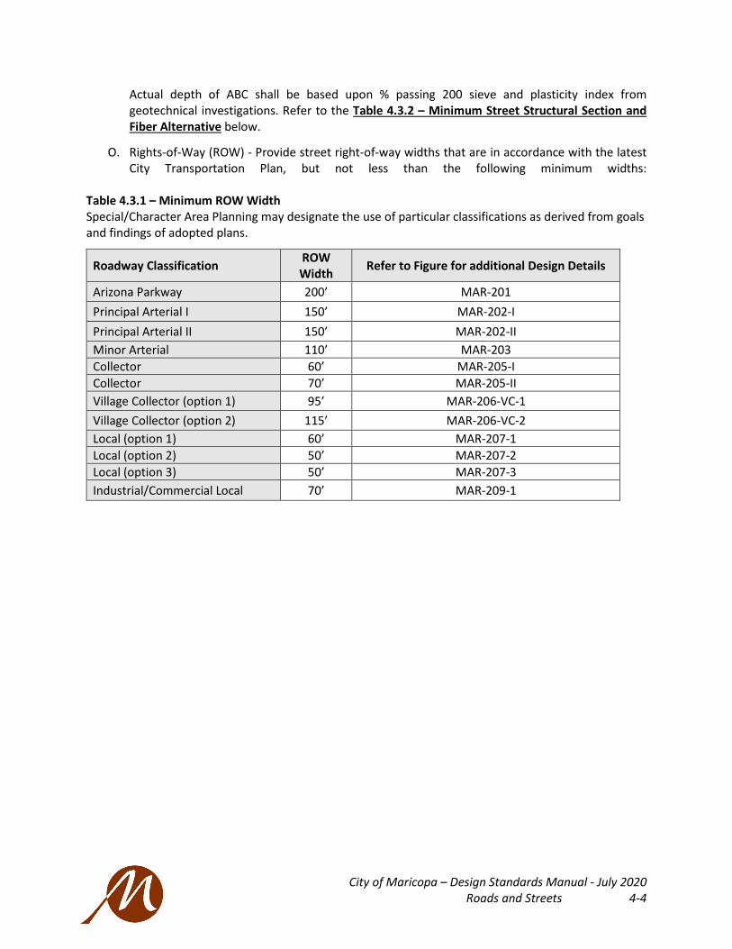
O. Rights-of-Way (ROW) - Provide street right-of-way widths that are in accordance with the latest City Transportation Plan, but not less than the following minimum widths:
Table 4.3.1 – Minimum ROW Width Special/Character Area Planning may designate the use of particular classifications as derived from goals and findings of adopted plans.
Roadway Classification ROW Width Refer to Figure for additional Design Details
Arizona Parkway 200’ MAR-201 Principal Arterial I 150’ MAR-202-I Principal Arterial II 150’ MAR-202-II Minor Arterial 110’ MAR-203 Collector 60’ MAR-205-I Collector 70’ MAR-205-II Village Collector (option 1) 95’ MAR-206-VC-1 Village Collector (option 2) 115’ MAR-206-VC-2 Local (option 1) 60’ MAR-207-1 Local (option 2) 50’ MAR-207-2 Local (option 3) 50’ MAR-207-3 Industrial/Commercial Local 70’ MAR-209-1

City of Maricopa – Design Standards Manual - July 2020 Roads and Streets 4-5
Table 4.3.2 – Minimum Street Structural Section and Fiber Alternative All Sections Without Fiber Fiber Alternative
Street Classifications
Untreated Base
(minimum)
Asphalt Base
Course
Asphalt Surface Course
Asphalt Base Course w/Fiber
Asphalt Surface Course
w/Fiber Arterial Roadway 10” * 4.5” - A19 1.5” - A12.5 3.5” – A19** 1.5” – A12.5** Collector Roadway 9” * 3.5” - A19 1.5” - A12.5 2.5” – A19** 1.5” – A1.25** Local Street – Residential (Rural & Estate, Low & Medium Density)
6” * NA 4” – R12.5 NA 3” – R12.5
Local Street - Residential (High Density)
8” * NA 4” – R12.5 NA 3” – R12.5
Local Street Commercial & Industrial
10” * NA 4” – R12.5 NA 3” – R12.5
Alley without Freight*** 6” * NA 3” – R12.5 NA 2” – R12.5
Mix Design designations are per East Valley Asphalt Committee (EVAC) All asphalt supplied must be currently approved by EVAC *Amounts shown are minimums. Actual depth of Aggregate Base Couse (ABC) is based upon % passing 200 sieve and plasticity index from geotechnical investigation **See approved Fiber Additive product in the Appendix ***Freight traffic on alleys require PCC pavement

City of Maricopa – Design Standards Manual - July 2020 Roads and Streets 4-6
Table 4.3.3 – Minimum Road Design Standards
(1) Consult with the City Engineer for the specific standard to be used.
* See Table 4.3.4 – Roadway Design Guidelines below.
Street Type/Category Arterial Collector Local Residential
Rural & Estate
Local Residential Low - High
Density
Local Commercial &
Industrial
Design Speed * * * * * Operational Speed * * * * * Posted Speed * * * * * Min. Radius of Horizontal Curves w/o Superelevations (ft)
1800 500 200 200 200
Min. Length of Tangent between Reverse Curves (ft) 300 100 100 100 100
Min. Length of Tangent between Curves - Same Direction (ft)
550 100 100 100 100
Min. Vertical Curve (ft) 500 100 100 100 100 Passing Sight Distance (ft) (per AASHTO) 1950 (1) (1) (1) (1)
Sight Distance Requirements (ft) (LT/RT) (per MAR-220) (1)
610/530 500/430 445/385 445/385 500/430
Min. Tangent Length Approaching Intersections (ft)
300 200 150 150 150

City of Maricopa – Design Standards Manual - July 2020 Roads and Streets 4-7
Table 4.3.4 – Roadway Design Guidelines
Roadway Design Guidelines
Guidance Criteria Parkway Arterials Collectors
Principal Arterial I Principal Arterial II Minor Arterial 60’ Collector 70’ Collector Village Collector - 1 Village Collector - 2
Standard Details listed in Sec. 10.1 Standard Plans and Roadway Details Index (See Appendix B) Street Purpose Mobility Mobility Mobility/Access Access Design Speed (MPH) 55 45-55 45-55 45 35 35 35 35 Posted Speed (MPH) 50 40-45 40-45 35-40 30 30 25 25 Right-of-Way Width (FT) 200 150 150 110 60 70 95 115 Number of Lanes 6 6 6 4 2 2 2 2 Street Width (back of curb) (FT) 109 109 109 75 37 49 71 91 Pavement Width (FT) 2 x 42.5 2 x 42.5 2 x 42.5 57 33 45 67 87 Lane Width (Directional) (FT) 12-14 12-14 12-14 12 10 10 12 12 Median Width/Left Turn Lane (FT)(1) 74 16 Single/ 28 Double LTL 16 Single/ 28 Double LTL 16 None 12 14 14 Painted or Curbed Curbed Curbed Curbed Curbed Painted Painted Painted
Curb/Edge Treatment Vertical Curb Vertical Curb Vertical Curb Vertical Curb Vertical Curb Vertical Curb
Shared-Use Paths/Sidewalks (FT) 2 x 14 SUP 2 x 14 SUP standard / 6 SW optional 6 SW 5 SW 6 SW 6 SW
Attached or Detached Detached with Landscape Buffer and Protected Intersections, see Standard Detail MAR-235 and MAR-236 Detached with Landscape Buffer
Bike Lanes (FT) (2) Bike Lanes are Not Advised for the benefit of all users 14 SUP standard – Contextual Exceptions may prefer Bike Lanes
2 x 6.5 Buffered (2’)
2 x 6.5 Buffered (2’)
2 x 6.5 Buffered (2’)
2 x 6.5 Buffered (2’)
Parking Not Allowed Not Allowed Not Allowed 10' Parallel (unstriped) 18’ Diagonal
w/in stripped shoulder; Diagonal includes 2' buffer
to Bike Lane
Transit Amenities Far side bus pullouts
Far side bus pullouts Bus Stop
(1) LTL = Left turn lane (2) Bike Lanes are omitted with use of a Shared-Use Path; if present, lanes require minimum of 4 feet uniform pavement width, 6.5 feet bike lanes anticipate 2 feet of curb/gutter

City of Maricopa – Design Standards Manual - July 2020 Roads and Streets 4-8
Table 4.3.5 – Access Management Guidelines
Access Management Guidelines
Guidance Criteria Parkway Arterials Collectors
Principal Arterial I Principal Arterial II Minor Arterial 60’ & 70’ Collector Village Collector 1 & 2
Access Management by Facility Type
Traffic Signal Spacing 1 mile; 1/2 mile where warranted & permitted
1/2 mile & 1 mile locations, where warranted, fully coordinated and progressed;
1/2 mi min for urban areas; 1 mi min for rural areas
1/2 mile; 1/4 mile locations, where warranted
Private / Public Street Access Spacing 1/2 mile Minimum; 1 mile preferred 1/2 mile Minimum; 1 mile preferred; (1/4 if warranted)
1/8 mile Minimum; 1/2 mile
preferred No Restrictions
Private Drive Access Spacing from Intersections See Table 4.20.1 – Driveway Separation by Street Type
See Table 4.20.1 –
Driveway Separation by Street Type
See Table 4.20.1 – Driveway Separation
by Street Type
See Table 4.20.1 – Driveway Separation by Street
Type
Private Drive Access Spacing from other Drives (feet) N/A; RI/RO only (2) 600 minimum; 1,200 preferred
450 minimum for RI/RO; Left-Out Limited at ¼ mile for major driveways
150 minimum; 300 preferred
Private Drive Access/Turning Movements RI/RO (1) only; U-turns at approved locations RI/RO (1) Preferred; Full access where approved (limited) Full access where approved (limited)
Private Drive Access Geometrics Right turns allowed; Turn lanes may be required
Private Drive Access-Remarks Per Arizona Parkway Design Guide (2) Allowed when no other access is available One access per parcel; Two for large
developments, when spacing standards can be met
(1) RI/RO= Turning movements restricted to right-hand turns into site and right-hand turns out of site (2) Arizona Parkway Design Guide in Appendix Part S

City of Maricopa – Design Standards Manual - July 2020 Roads and Streets 4-9
4.4 STREET CLASSIFICATION IN APPLICATION
All street classifications are further defined in Table 4.3.4 – Roadway Design Guidelines.
A. The Arizona Parkway (Standard Detail MAR-201) 1. The Parkway is intended to be a six-lane, intermediate facility between the Principal Arterial
configuration and the Freeway configuration. The Parkway is intended to provide a more moderate speed facility than the Freeway and a wider, more open corridor than a Principal Arterial.
2. Left turns are typically prohibited at an Arizona Parkway intersection, resulting in an efficient two-phase signal operation that facilitates uninterrupted flow of through traffic on the parkway. With left turns prohibited, motorists wishing to turn left are typically provided the opportunity to execute a downstream U-turn at a median break, leading to a right turn in the desired direction of travel. This concept substantially increases the capacity of an Arizona Parkway by comparison with a Principal Arterial.
3. As an alternative, motorists may be directed into a series of right turns on smaller capacity streets resulting in a routing that leads to the desired direction of travel.
B. Arterials 1. The Arterials are major streets, generally of a four- or six-lane configuration located on the
one-mile grid system. Principal Arterials are intended to carry the major portion of through traffic from one portion of the City of Maricopa to another and to connect with the regional highway system.
2. The cross-street intersections and connections to the Arterials by Collectors are: a. limited to locations by the Access Management Guide b. designed to the intersection specifications of Standard Detail MAR-234.
3. The ideal section achieves a low-stress separated bikeway experience to accommodate a variety of bike users. The alternative is a bike lane adjacent to a travel lane, only to accommodate a physical design constraint.
4. The three types of Arterials are given below: a. Principal Arterial I (Standard Detail MAR-202-I)
• The Principal Arterial I is a moderate to high-speed facility with controlled, limited access to adjacent properties
b. Principal Arterial II (Standard Detail MAR-202-II) • This alternative allows for a double left turn lane.
c. Minor Arterial (Standard Detail MAR-203) • The Minor Arterials are semi-major streets, generally of a four-lane configuration
also located on the one-mile grid system. Minor Arterials are intended to serve the majority of the areas within the City of Maricopa where anticipated traffic volumes do not warrant the higher standard Principal Arterials.
• Design intersections of two Minor Arterials as specified in Standard Detail MAR-235.
C. Collectors (Standard Details MAR-205-I and MAR-205-II) 1. The standard collectors, in residential and commercial contexts, are generally a two-lane
facility with a center turn lane (when warranted) intended to serve as a connection between the Local Streets and the Arterials or Parkways. The travel way of the street may feature two-way left turn lane if warranted. The standard details provide some variety of Collector standards for different traffic conditions.

City of Maricopa – Design Standards Manual - July 2020 Roads and Streets 4-10
D. Village Collectors (Standard Detail MAR-206-VC-1 and MAR-206-VC-2) The Village Collector 1 and Village Collector 2 are intended to serve activity centers where access and safety will be higher priority than mobility. Pedestrian capacity is desired with public spaces adjacent to the right-of-way line.
1. The cross-street intersections for Village Collector 1 are more frequent with shorter intervals than they are on the Collectors. The access points to adjacent property, either commercial or residential, are limited, but allowable in certain, justifiable situations.
2. The Village Collectors accommodate parking on both sides of the roadway. Depending on parking demand planned for adjacent land uses, the parking can be configured as parallel or diagonal.
E. Local Streets (Standard Detail MAR-207-1, -2, and -3) 1. The Local Street provides local access for the individual residential lots, residential,
commercial, or industrial. Different parking schemes are available based on pavement width. Dedicated bikeways are not provided.
2. Posted speed limit shall not exceed 25 mph. 3. Long straightaways or intersections with trails will warrant the inclusion of a choker or
similar traffic calming treatment.
F. Local Industrial/Commercial (Standard Detail MAR-209) 1. The Local Industrial/Commercial Street provides local access for the individual
industrial/commercial lots. Parallel parking is allowed on both sides of the street. Dedicated bikeways are not provided.
2. The access driveway spacing is determined by the spacing of the residential, commercial, or industrial lots.
3. Posted speed limit shall not exceed 35 mph.
G. Asphalt Rock Dust Palliative Roadway (Standard Detail MAR-208) 1. The Asphalt Rock Dust Palliative Roadway is typically used in special cases for dust
mitigation. The surfacing is typically a thin bituminous top layer (chip seal) to serve low traffic volumes.
2. Heavy trucks are typically prohibited. 3. The Design Speed and the Posted Speed for the Asphalt Rock Dust Palliative Roadway both
vary.
H. All-Weather Emergency Access, as required by International Fire Code (IFC) 1. For development lacking a fully-improved, paved second point of access. 2. Secondary points of emergency access shall be a minimum of six inches (6”) ABC compacted
to 95%, and maintained to sustain the weight of a fire apparatus. 3. Access shall be improved to twenty feet (20’) wide. 4. Primary and secondary points of access cannot be subjected to the same likely route
impairment or event. 5. Secondary access shall comply with IFC standard for remoteness. 6. Additional information in Appendix F.
4.5 ATYPICAL STREET SECTIONS
Atypical contexts may warrant unique Street Sections distinct from the adopted standards. In these cases, design flexibility may be considered for context-sensitive design criteria.

City of Maricopa – Design Standards Manual - July 2020 Roads and Streets 4-11
A. The City Engineer provides the following list of publications as guidance for and quality examples of contextual adaptations: 1. Institute of Transportation Engineers (ITE): Designing Walkable Urban Thoroughfares: A
Context Sensitive Approach, (current edition) 2. AASHTO: AASHTO Guide for the Development of Bicycle Facilities, (current edition) 3. Greater Phoenix Metro Green Infrastructure Handbook: Low-Impact Development Details for
Alternative Stormwater Management, (current edition/equivalent)
4.6 RESERVED
Character Area Roads.
4.7 STREET NAMING GUIDELINES
A. Purpose. The City of Maricopa has Street Naming and Addressing Procedures (SNAP) in a separate document fulfilling the following needs: 1. Uniform and consistent street names and addresses to enable emergency response
personnel as well as the general public to readily locate a street address. 2. Increased efficiency of delivery services, including the United States Postal Service. 3. Consistent and accurate legal documents. 4. Convenience and proper orientation for travelers and citizens of the City of Maricopa. 5. Set procedures for City Staff and applicants.
4.8 RIGHT-OF-WAY (ROW) REQUIREMENTS
A. When required, the acquisition and dedication of new street ROW and/or easements shall be coordinated through the City of Maricopa. See Subdivision Ordinance for ROW abandonments requirements.
B. Conveyance documents shall include, at a minimum, the following: 1. Legal descriptions 2. Current Title report 3. Scaled drawings per the requirements of the Pinal County Recorder’s Office 4. Prepared and sealed by a registered land surveyor within the State of Arizona 5. Submitted by the applicant to the City of Maricopa for approval and recording
C. In review of the standard ROW for the classification of a Street, additional ROW may be required under the following circumstances: 1. To include cut or fill slopes that cannot be contained within the standard ROW width required
for the Classification of the Street. 2. Where the standard minimum clear sight distances on horizontal curves cannot be obtained. 3. Where the standard minimum clear sight distances at intersections cannot be obtained. 4. Where auxiliary traffic lanes (left or right turning lanes) and/or deceleration lanes are
required. 5. Locations where future bus bays will be required, see 4.21 Transit Infrastructure. 6. Cul-de-sacs. 7. Intersections, see 4.16 Intersection Standards. 8. Roundabouts. 9. Other conditions that may be required by the City Engineer.

City of Maricopa – Design Standards Manual - July 2020 Roads and Streets 4-12
4.9 PUBLIC UTILITY EASEMENTS (PUE)
For further details regarding utilities, see Part 6 Utility Requirements.
A. Dedicated Public Utility Easements (PUE), a minimum of 8 feet in width, shall be located outside of, and adjacent to, each side of the dedicated street ROW for all streets. 1. Special conditions may be applied to developments with alleys and zero setback development
(PUE standards may be altered). 2. The PUE shall be dedicated to the City of Maricopa and shall be a non-exclusive easement for
the purpose of permitting and licensing construction, installation, modification, operation, maintenance, repair, replacement, removal, and reinstallation of all underground utilities and aboveground structures, facilities, and appurtenances related thereto.
B. Dedicated Public Utility Easements (PUE) shall not: 1. be located within the side or rear property lines of subdivision lots. A separate tract shall be
provided outside the street ROW, between the ROW line and the side or rear property lines of the adjacent lots, to sufficiently contain the PUE;
2. be used for storm water retention and no portion of a retention basin side slope shall be located within a PUE.
4.10 HORIZONTAL ALIGNMENT
Horizontal Curves on all Streets shall be designed in conformance with American Association of State Highway and Transportation Officials (AASHTO) Standards and Requirements based on the design speed of the road or street.
4.11 VERTICAL ALIGNMENT
Vertical Curves on all Streets shall be designed in conformance to AASHTO Standards and Requirements based on the design speed of the road or street. The minimum longitudinal slope for all street classifications of Principal Arterial and less is 0.20%.
4.12 CURB RETURNS
A. Curb returns at all intersections shall be per the MAG STD DTL 220-1, Type A, 6-inch vertical curb and shall include the sidewalk ramp per the MAG STD DTL 236 standard requirements with the detectable warning device.
B. The use of 4-inch vertical curb, in lieu of the 6-inch vertical curb, may be allowed with prior approval by the City Engineer, in those cases where the street curb and gutter on both sides of the curb return is the MAG STD DTL 220, Type C, 4-inch roll curb and gutter.
C. A five (5) foot transition between 6-inch and 4-inch vertical curb and gutter and the 4-inch roll curb and gutter, per MAG STD DTL 221, shall be provided at all locations where the curb and gutter changes from one type to the other. In areas with curb ramps, medians shall not extend beyond the beginning of the curb return unless a pedestrian refuge is included within the median.
D. Vertical curb and gutter, and 5-foot transitions, per MAG Standards, as necessary are required on all streets where the curb is adjacent to a tract and/or open space.
E. Vertical curves are required at all locations where grade breaks exceed an algebraic difference of: 1. 1% on arterial streets 2. 2% on collector and local (residential) streets

City of Maricopa – Design Standards Manual - July 2020 Roads and Streets 4-13
F. Standard curb radii, as measured at the Back of Curb (B/C), shall be as follows (alternatives may be considered for traffic calming in pedestrian areas): 1. Arizona Parkways = 40 feet 2. Arterials = 35 feet 3. Collectors = 30 feet 4. Locals = 25 feet 5. The larger radii of different standards at intersections shall prevail as the design standard.
Radii at intersections Parkway Arterial Collector Local Parkway 40 ft 40 ft 40 ft 40 ft Arterial 40 ft 35 ft 35 ft 35 ft
Collector 40 ft 35 ft 30 ft 30 ft Local 40 ft 35 ft 30 ft 25 ft
Protected Intersection for Shared-Use Paths
Mountable truck apron radii of 15 ft See Figure 4.12.1 – Mountable Truck Apron at Protected Intersection
Special Planning Area Reductions desired for traffic calming
6. Protected intersections with Shared-Use Paths require corner islands with the radii standards above, with additional truck aprons. The corner island uses standard radii from table above. Figure 4.12.1 – Mountable Truck Apron at Protected Intersection
Image originally from MassDOT Separated Bike Lane Planning & Design Guide
4.13 SIDEWALK RAMPS
A. Streets with a typical sidewalk shall use directional sidewalk ramps at all intersection curb returns per the requirements of MAG STD DTL 237. 1. Sidewalk ramps are required opposite all curb return sidewalk ramps at “T” street intersection
curb returns. The sidewalk ramp shall conform to MAG STD DTL 238-1. Directional sidewalk ramps are required on “T” street intersection curb returns of local streets. Residential driveways shall not be considered as ramp access for pedestrian purposes. There must be a minimum 5-foot clearance between a sidewalk ramp and a driveway.
2. Subgrade compaction requirements for sidewalk shall be per MAG Specifications. 3. Sidewalk ramps are required at all intersections of recreational trails and street sidewalks.
The sidewalk ramp shall conform to MAG STD DTL 237 at street intersections curb return locations and per MAG STD DTL 238-1 at mid-block locations. The ramp may require modifications to meet the surface of the Trail on the backside. Such modifications must be detailed on the plans.
4. Sidewalk ramps shall have a maximum offset of ten (10’) feet from ramp to ramp.
B. Shared-Use Paths shall be designed with vertical curves and slopes for comfortable and safe multimodal use and be treated as an accessible route. 1. Subgrade compaction requirements for sidewalk shall be per MAG Specifications. 2. For intersection design, see Sec. 4.16 Intersection Standards.
Corner Island; Radius per 4.12.F
Truck Apron; 15’ Radius
City of Maricopa – Design Standards Manual - July 2020 Roads and Streets 4-14
C. All crosswalk ramps shall meet the current requirements of Federal ADA Standards.
4.14 PEDESTRIAN REFUGES, MIDBLOCK CROSSINGS, AND INTERSECTIONS
A. A pedestrian refuge is required at: 1. Midblock recreational trail crossings at any arterial street. See Maricopa standard detail MAR-
228. 2. Intersections where a raised median extends beyond the curb return of any adjacent
intersection corner, a custom pedestrian refuge may be designed per City Engineer’s acceptance. Per US Access Board, R305.4.1, Medians and pedestrian refuge islands shall be six feet (6’) minimum in length in the direction of pedestrian travel, ten feet (10’) preferred.
3. Signalized intersections of Principle Arterial II either newly constructed or reconstructed. See Maricopa Standard Detail MAR-228-1.
B. A pedestrian refuge is advised at: 1. Intersection street crossings where crossing times do not meet guidelines of the Manual on
Uniform Traffic Control Devices (MUTCD). 2. Midblock Crossing where the crossing is greater than sixty feet (60’) curb to curb.
C. Midblock crossings with or without a refuge are required as follows: 1. When intersection spacing is:
a. greater than 400 feet, and/or b. where 500 feet of additional pedestrian travel is required to reach the nearest
existing/planned crosswalk. 2. Where there is concentrated pedestrian traffic near beneficial destinations, such as schools,
shopping centers, or transit stops at the direction of the City Engineer. 3. Guidelines for where midblock crossings should be used include:
a. Multilane streets carrying less than 15,000 ADT with a raised pedestrian refuge median. b. Adapt for operating speeds, if warranted. c. Adequate sight distance areas. d. Adequate lighting areas. e. Observe crossing behavior and use after crossing improvements; adapt the design if
warranted. 4. Traffic calming in advance of the midblock crossing should be implemented (see 4.18 Traffic
Calming).
D. Refer to MUTCD for details concerning high visibility crossing markings, Z crossing configurations, locator tones and audio pedestrian signal outputs to name a few of the recommended safety features.
E. For Special Planning Areas anticipating higher pedestrian presence, apply design deference for refuges and traffic calming in the MAG Pedestrian Policies and Design Guidelines (current edition).
4.15 DETECTABLE WARNING SURFACE
A. Detectable warnings shall be installed at ramps or edges where a walkway crosses a vehicular way.
B. Materials 1. Detectable warning surfaces shall be textured to provide slip resistance and shall contrast
visually with adjacent walking surfaces; either light on dark or dark on light.

City of Maricopa – Design Standards Manual - July 2020 Roads and Streets 4-15
2. Color shall be integral with the detectable warning device and shall not be surface applied. Paints or other surface coating shall not be used.
3. Pre-manufactured detectable warning surfaces shall be wet-set products that generally include rigid products pressed into freshly formed concrete.
C. Dimensions 1. The edge of the detectable warning surface nearest to the curb line and/or edge of roadway
surface shall be located a minimum of ten (10) inches from the face of curb line and/or edge of roadway surface.
2. Detectable warnings shall be in full compliance with ADA accessibility guidelines. 3. Domes shall be aligned on a square grid aligned in rows parallel and perpendicular to the
predominant direction of travel. Domes shall not be skewed diagonally to the direction of travel.
4.16 INTERSECTION STANDARDS
A. Intersection design shall emphasize safety and comfort for all users through multimodal design. 1. Standards for intersection design emphasize safety for all users with high contrast crosswalks,
stop bars that increase visibility for permissive right-hand turns, protected bikeways, and appropriate street light placement. Refer to: a. Standard Detail MAR-235 for Minor Arterial to Collector design. b. Standard Detail MAR-236 for Minor Arterial to Minor Arterial design.
2. Right-of-Way (ROW) requirements depend on requirements of intersection design. Standard Details illustrate minimum requirements in typical conditions. Additional ROW may be required for dedicated right-hand turn lanes (or similar).
3. Shared Use paths are to be accessible routes with running slopes and cross slopes to comply with ADA design standards. Designs should promote safe crossing speeds (8- 12 MPH) for cyclists as they navigate the potential conflicts of the intersection.
4. For property lines and ROW at typical local corners, see 4.3 Street Design.
B. Sight Distance Requirements 1. Sight visibility triangles are required at all intersections. Refer to Standard Detail MAR-220 for
further information on how to determine the sight distance triangle depending on the vehicular speed and type of roadway.
C. Roundabouts serve to manage intersecting traffic otherwise controlled by stop conditions or traffic signals. ROW requirements shall be a minimum of one-foot outside the design elements of the roundabout. MCDOT Design Guidance is provided in Appendix Q. 1. Local-to-Local Roundabouts
a. Radius of 20’ to 25’. b. Circulating roadway requires the turning template WB-50 to fit face of curb to face of
curb. c. Raised splitter islands are to be used on all approaches. The design approach speed for
neighborhood roundabouts will be 20 mph, with the posted speed following current City guidelines.
2. Local-to-Collector Roundabouts a. Roundabouts are single lane with single lane approaches. b. Residential collector intersections will follow the same guidelines as local intersections.

City of Maricopa – Design Standards Manual - July 2020 Roads and Streets 4-16
c. Commercial collector intersections require a larger central island radius with truck aprons.
d. Circulating roadway requires the turning temple WB-50 to fit face of curb to face of curb.
3. Larger Thoroughfare Roundabouts a. Roundabouts for collector/collector, collector/arterial, and arterial/arterial intersections
need to be approved on a case by case basis by the City Engineer. b. Locations recommended for roundabout design should be evaluated based on the
following factors: • Where stop signs result in unacceptable delays for crossroad traffic • Where a high left-turn percentage on one or more legs exists • Where a disproportionately high number of accidents involve crossing or turning
traffic • Where it is not desirable to give priority to either roadway • Intersections with unusual geometry or physical constraints • Uniform and acceptable approach speeds on all legs
c. Locations are not typically recommended for the following intersections but may be considered with City approval: • On a collector/arterial where any leg is posted 45 mph or higher, unless adhering to
recommended approach speeds immediately prior to the entry curves (per FHWA Guidelines)
• Where the grade for any leg exceeds 4% • Where traffic volumes are unbalanced with higher flows on one or more of the
approaches • Where a collector/arterial intersects a local and a roundabout would result in
unacceptable delays to the collector/arterial • High pedestrian activity including special needs pedestrians • Where there is inadequate sight distance • Where there is a large volume of bicycle traffic • Where there is a large volume of freight traffic • Where a downstream traffic control device such as a traffic signal would result in a
queue that extends into the roundabout • At a single intersection in a network of linked traffic signals
d. Locations where roundabouts are not recommended include intersections: • Where a satisfactory design cannot meet FHWA Design Guidelines • Where a signal interconnect system provides a better level of service • Where it is desirable to adjust traffic movements via signal timing
4.17 VALLEY GUTTERS
A. Valley gutters and aprons shall be per MAG STD DTL 240.
B. No water valve covers, manhole rims, or other appurtenances shall be located within valley gutters unless otherwise approved by the City Engineer.
C. Valley gutters shall be provided at all locations where storm water drainage crosses the street. The width and standard detail number shall be shown on the plans. The crown of the street shall be tapered out by a crown warp section, starting 40 feet from the centerline of the valley gutter.
City of Maricopa – Design Standards Manual - July 2020 Roads and Streets 4-17
D. At all Local Street to Local Street intersections, the minimum width of the valley gutter is three (3) feet. At all mid-block locations on Local Streets, the minimum width of the valley gutter shall be a modified MAG STD DTL 240 eight (8) feet in width.
E. At all Collector Street intersections with Arterial Streets, where a valley gutter is required, the minimum width of the valley gutter shall be six (6) feet.
F. Arterial to Arterial intersections should be designed without valley gutters. However, if necessary, to convey street flows through an Arterial to Arterial Street intersection, an eight (8) foot valley gutter is required.
4.18 Traffic Calming
A. Traffic calming devices shall be installed along all newly constructed local streets with single-family residential frontage on straight or nearly straight segments over 1000 feet in length. 1. Typical traffic calming devices include roundabouts, chicanes, and chokers.
a. Chokers should be spaced about 300 to 500 feet apart. See detail MAR-225. b. Use of bulb-outs (also known as curb extensions) at intersections are required where
sidewalk ramps align with trails, they are encouraged at all local-to-local intersections. See detail MAR-225-I.
c. Alternative traffic calming options for a specific roadway or subdivision require approval of the City Engineer.
2. Speed bumps are highly discouraged.
4.19 PAVEMENT STRUCTURAL DESIGN STANDARDS
A. Flexible Pavement (Asphaltic Concrete) 1. The Pavement Structural Design Sections shall comply with the following material
specifications: a. All Asphaltic Concrete Pavement shall comply with current East Valley Asphalt Committee
(EVAC) standards. b. The sub grade shall be prepared in accordance with MAG STD SPEC 301. c. Base course construction and materials shall conform to MAG STD SPEC 310 and 702. d. Asphaltic concrete pavement construction and materials shall conform to MAG STD SPEC
321 and 710. e. Fog seal shall be applied to the surface within 1 year of the asphalt placement, prior to
the end of the warranty period, in accordance to MAG STD SPEC 333.
B. Rigid Pavement (Portland Cement Concrete / PCC) 1. Rigid (Portland Cement Concrete) Pavement is not the preferred roadway treatment, but it
can be used, within the limits of intersections, if it can be justified and must be approved in advance by the City Engineer.
2. All Portland Cement Concrete (PCC) Pavement shall comply with the current MAG STD SPEC 324.
3. Portland Cement Concrete (PCC) Pavement shall be used for 10-feet of width for the Shared Use Path design at 5 inches thick on compacted earth base. The remaining width (4-feet typ.) can be compacted and stabilized DG at 4 inches deep (see Pavement Alternative below).

City of Maricopa – Design Standards Manual - July 2020 Roads and Streets 4-18
C. Textured Entryway Drives and Decorative Pavement 1. If decorative pavement is desired on Collector Streets or lower intensity roadways, at the
entrances into a subdivision, or on driveways into commercial or industrial developments, it must be approved by the City Engineer. The decorative surface preferred for such type driveways and entrances allowed within the ROW shall be stamped concrete.
2. Decorative stamped concrete pavement shall be constructed in accordance with the MAG STD SPEC 340 and 725 and shall be per the Geotechnical Report with minimums of: a. six inches (6”) of subbase, and b. pavement thickness of eight inches (8”) with wire mesh reinforcement, and c. Class A Concrete with 28-day compressive strength of 3000 psi.
3. Interlocking concrete pavers shall be an acceptable pavement method to be used in medians, crosswalks, intersections, and other areas as approved by the City Engineer and shall be installed in accordance with MAG STD SPEC 342, 702-1 (ABC) and 725 (Portland Cement Concrete).
4. Exposed aggregate concrete is an acceptable paving method in areas designed for decorative or pedestrian use only and shall be installed in accordance with MAG STD SPEC 343, and 725 (Concrete). It shall not be used in areas subject to vehicular traffic.
5. All maintenance of the decorative treatment shall be the complete responsibility of the Homeowners Association (for Residential Developments) or the Property Owners’ Association (for Commercial or Industrial Developments) and must be noted on the construction plans and recorded in the Covenants, Conditions, and Restrictions associated with the property. Refer to the Subdivision Regulations, Design Standards for further information.
6. Coloring pigments shall be applied integrally to the concrete. Air entraining admixtures, coloring pigments, integral water repellents, and finely ground silica shall be previously established as suitable for use in concrete and either shall conform to ASTM standards where applicable or shall be shown by test or experience not to be detrimental to the concrete.
D. Pavement Alternative: Cement-Modified Soil 1. Blending cement, water, native soils (and amendments as needed) to produce a compacted
permanent finish at low costs and reducing heat gain and urban heat island effects. 2. Applications: Parking and Low-Volume roads, Low-Speed Drives, as a stabilizer of subgrade in
areas of inferior soils, per AASHTO defined volumes. 3. Trails may use soil stabilizer product within compacted 1/4” minus DG at a 4-inch thickness. 4. See “Sample Cement-Modified Soil Specification” in Appendix B.
E. Temporary Turn Arounds 1. Temporary turn arounds at project phase lines shall be 6” ABC on compacted sub grade per
MAG STD SPECS 301, 310 and 702.
F. Temporary Pavement Section 2. Minimum temporary pavement sections shall be 2” AC on 4” ABC on compacted sub grade
per MAG STD SPECS 301, 310 and 702. Temporary pavement sections shall only be used for the duration of the related construction project unless otherwise approved by the City Engineer. Temporary pavement sections shall be adequate for the local traffic loading and soil conditions of the roadway and shall be maintained by the general contractor for the duration of the interim condition.

City of Maricopa – Design Standards Manual - July 2020 Roads and Streets 4-19
4.20 ACCESS DRIVES INTO PRIVATE DEVELOPMENTS
A. Driveway Separation Requirements 1. Driveway Separation from other Driveways, see Table 4.3.5 – Access Management
Guidelines. 2. Driveway Separation from Intersections, see Table 4.20.1 – Driveway Separation by Street
Type from Intersections and Figure 4.20.1 – Driveway Separation by Street Type. Table 4.20.1 – Driveway Separation by Street Type from Intersections
WITH RAISED MEDIAN
Connection Type ≥ 45 MPH < 45 MPH Arterial Arterial Urban All Other Collector Local
1. Right-in/Right-Out (Upstream of Intersection) 440 ft 125 ft 250 ft 85 ft -
2. Right-In/Right-Out (Downstream of Intersection) 660 ft 125 ft 250 ft 175 ft -
WITHOUT RAISED MEDIAN
Connection Type ≥ 45 MPH < 45 MPH Arterial Arterial Collector Local
3. Driveway Upstream of Intersection 440 ft 250 ft 175 ft 50 ft 4. Driveway Downstream of Intersection 660 ft 250 ft 175 ft 50 ft
Notes:
5. Urban is defined as an area with surrounding population density greater than 1 dwelling unit per acre 6. Minimum connection spacing criteria for corner clearance should only be considered when greater spacing cannot be
achieved 7. It is desirable to maximize the distance between the corner parcel connection and adjacent intersections
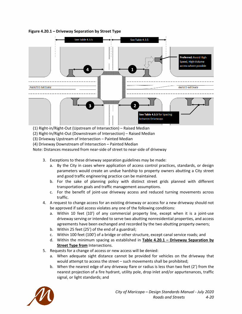
City of Maricopa – Design Standards Manual - July 2020 Roads and Streets 4-20
Figure 4.20.1 – Driveway Separation by Street Type
(1) Right-in/Right-Out (Upstream of Intersection) – Raised Median (2) Right-In/Right-Out (Downstream of Intersection) – Raised Median (3) Driveway Upstream of Intersection – Painted Median (4) Driveway Downstream of Intersection – Painted Median Note: Distances measured from near-side of street to near-side of driveway
3. Exceptions to these driveway separation guidelines may be made: a. By the City in cases where application of access control practices, standards, or design
parameters would create an undue hardship to property owners abutting a City street and good traffic engineering practice can be maintained.
b. For the sake of planning policy with distinct street grids planned with different transportation goals and traffic management assumptions.
c. For the benefit of joint-use driveway access and reduced turning movements across traffic.
4. A request to change access for an existing driveway or access for a new driveway should not be approved if said access violates any one of the following conditions: a. Within 10 feet (10′) of any commercial property line, except when it is a joint-use
driveway serving or intended to serve two abutting nonresidential properties, and access agreements have been exchanged and recorded by the two abutting property owners;
b. Within 25 feet (25′) of the end of a guardrail; c. Within 100 feet (100′) of a bridge or other structure, except canal service roads; and d. Within the minimum spacing as established in Table 4.20.1 – Driveway Separation by
Street Type from Intersections. 5. Requests for a change of access or new access will be denied:
a. When adequate sight distance cannot be provided for vehicles on the driveway that would attempt to access the street – such movements shall be prohibited;
b. When the nearest edge of any driveway flare or radius is less than two feet (2’) from the nearest projection of a fire hydrant, utility pole, drop inlet and/or appurtenances, traffic signal, or light standards; and

City of Maricopa – Design Standards Manual - July 2020 Roads and Streets 4-21
c. Where parking or loading areas would require backing maneuvers into a public right-of-way, except for single-family or duplex residential uses on local roads.
d. Where alley-only access has been determined as functionally necessary. 6. If a property has frontage on more than one street, access will be permitted only on those
street frontages where standards provided under these access management guidelines and other applicable City Regulations can be met.
7. If any access point meeting the standards presented herein cannot serve a property: a. The City may designate one or more access points by waiving one or more standards; and b. Designation of an access point(s) with waiver of standards can be based on a traffic safety
analysis, operational needs, and conformance to as many of the requirements in these guidelines as possible.
8. The location of access for properties on opposite sides of a roadway or highway shall be coordinated, to the degree practicable, so vehicles moving into and out of the access drive will not be in conflict (i.e., interfere with each other). The following guidelines should be followed in coordinating opposing driveway locations where a raised median is not present to negate turning conflicts: a. Driveways should be located directly opposite each other to ensure a single access point
is shared with respect to the roadway; b. Where lots are not sufficiently large enough to allow access points on opposite sides of
the street to be aligned, driveway centerlines not in alignment normally will be offset a minimum of 150 feet (150′) on all collector roads and 330 feet (330′) on arterial roads – greater distances may be required, if left-turn storage lanes are present; and
c. Joint access may be implemented for two adjacent developments, where the proposed new access will not meet spacing requirements set forth herein, subject to review and approval by the City Engineer.

City of Maricopa – Design Standards Manual - July 2020 Roads and Streets 4-22
B. Driveway Width and Curb Return Radii 1. All Driveways onto Arterial Streets or Collector Streets must be curb return type (MAG STD
DTL 251) driveways. The dimensions for the driveways are shown in the following table: Table 4.20.2 – Driveway Dimensions
C. Right Turn Deceleration Lane into Developments 1. A Right Turn Deceleration Lane is to be installed when warranted by a Traffic Impact Analysis
or Traffic Impact Letter. Refer to TIA guidelines in this Manual. 2. Where successive driveways warranting provisions of right-turn deceleration lanes are less
than 400 feet apart (measured centerline of driveway to centerline of driveway) a continuous right turn lane, rather than separate right-turn lanes, shall be constructed.
3. Where a driveway warranting provision of a right-turn deceleration lane is located less than 450 feet in advance of an Arterial cross-street, a continuous right-turn lane, rather than separate right-turn lanes, shall be constructed.
D. Right In / Right Out Situations 1. Right-in, right-out access points may be installed when warranted by a Traffic Impact Analysis
or Traffic Impact Letter. Refer to Part 5 Traffic Impact Analysis and Standard Detail MAR-234.
E. Left Turn Lanes into Developments 1. A left turn lane is to be installed when warranted by a Traffic Impact Analysis or Traffic Impact
Letter. Refer to TIA guidelines in this Manual.
F. Sight Distance Requirements 1. Sight visibility triangles are required at all driveways. Refer to Standard Detail MAR-220 for
further information on how to determine the sight distance triangle depending on the vehicular speed and type of roadway.
RECOMMENDED DRIVEWAY DIMENSIONS (To Face of Curb)
ALONG ARTERIAL AND COLLECTOR STREETS
Driveway Parameter
Multi-Family Residential
Commercial Driveway
Industrial Driveway (1)
Minimum Width (1-Way) 12 feet 16 feet 16 feet
Minimum/Maximum Width (2-Way) 24 / 30 feet 24 / 40 feet 24 / 40 feet
Standard Corner Radius 25 feet 25 feet 25 feet
Minimum Corner Radius (posted 35 mph or less) 20 feet 20 feet 25 feet
(1) At an Industrial Driveway, the corner radius and driveway lane width should be dimensioned to accommodate the truck turning radius without encroachment into a(n):
a. Arterial Street traffic lane. b. Opposing traffic within the driveway. c. Exceptions may be considered with the City Engineer’s review and approval.

City of Maricopa – Design Standards Manual - July 2020 Roads and Streets 4-23
G. Shared Use Paths across driveway accesses shall be marked clearly and bend out to accommodate a car length of yield space out of the flow of the traffic lane, unless a deceleration lane is provided for right turns.
Figure 4.20.2 – Shared-Use Paths Crossing Access Drives
Figure originally from MassDOT Separated Bike Lane Planning & Design Guide (as example)
4.21 TRANSIT INFRASTRUCTURE
A. Bus Bays / Bus Pullouts 1. Bus bays are typically placed on Arterial Streets along existing or planned transit routes, at
locations selected by City Staff, in accordance with the following requirements and dimensions of Standard Detail MAR-223 and MAR-224.
2. Bus bays are expected at a minimum of one-mile intervals along Arterial Streets with existing or planned bus routes. A far-side easement is required at all arterial/arterial intersections and may be required at the far side of arterial/collector intersections if warranted. Easement requirements on the far-side of arterial/arterial intersections are illustrated in MAR-223.
3. Additional bus bay locations, if warranted, may be spaced at one-half mile intervals with prior approval by the City Engineer.
4. Bus bays should be located at transfer points and layover locations at the end of bus routes. 5. Unless circumstances require otherwise, a minimum 10-feet of curb shall extend tangent from
the start of the entry taper for a bus bay location unless the bay is located just downstream from the intersection curb return.
6. Bus bays are desirable where one of the following conditions exists: a. Street traffic speeds are 40 MPH or more b. Peak period boarding average exceeds five people per bus c. Average peak period dwell time exceeds 30 seconds per bus d. A high frequency of accidents involving buses occurred within past year e. Two traffic lanes or less exist in one direction of travel
7. The City will require a transit easement for all bus pullouts in accordance with the dimensions shown in the details.
B. Bus Stop Design, See Standard Details MAR-223 and MAR-224 1. A bus stop may exist on-site or adjacent to a thoroughfare with or without the presence of a
bus bay. Bus bays may be omitted if deemed unwarranted. 2. Bus stop pads must not interfere with pedestrian traffic on the adjacent sidewalk.

City of Maricopa – Design Standards Manual - July 2020 Roads and Streets 4-24
3. Bus stops require an 8-foot by 8-foot concrete pad, which is a continuous, unobstructed solid area contiguous to the curb and to connect to a sidewalk or an extension of the sidewalk. A paved shared-use path is equivalent to a sidewalk.
4. Surfaces must be stable, firm, and slip resistant. Any drop greater than ½ inch or surface grade steeper than 1:20 requires an ADA compliant ramp.
4.22 SURVEY MONUMENTS
A. Survey Monuments and Markers, per MAG STD DTL 120-1, Type B, shall be installed: 1. At the intersections of all Street Centerlines. 2. At the location of all points of curvature (PC) and points of tangency (PT) of the street
centerline curves. 3. Centerline and property line at stub-out of streets. 4. Monuments are required to be stamped with surveyor registration number and “City of
Maricopa”
B. Survey monument markers per MAG STD DTL 120-1 Type A shall be installed at section line intersections.
4.23 PARTIAL AND HALF-STREET STANDARDS
A. Improvements to the complete street cross-section are required for the streets internal to new development.
B. Half-street improvements are acceptable for streets adjacent to new development. 1. The design of the half-street on facility types of Principal Arterial, Minor Arterial, or Collector
shall provide 28 feet of pavement, at a minimum, with striping for two-way traffic. 2. Half-street conditions are not permitted on local streets. 3. Half-streets intended to include a raised median shall construct the full median including
landscaping. 4. All standard street and utility improvements, including curb and gutter, sidewalk, drainage
facilities, street signs, streetlights, fire hydrants, landscaping, etc., required on the side of the half-street adjacent to the development property shall be fully constructed.
C. Reference Part 5 Traffic Impact Analysis guidelines within this Manual to verify that partial and half-streets provide adequate improvements to serve projected traffic.
D. Utilities under pavement are typically to be accessible for future development. 1. All water and sewer line extensions must extend beyond the point of connection of the
intersecting street for future utility tie-ins eliminating future pavement cuts. Extensions must extend beyond curb return of intersecting street. Extensions must not terminate beneath a valley gutter.
2. Exceptions may be warranted when adjacent property is infeasible for utility service provider.
E. Adequate pavement tapers shall be constructed to provide transitions between the newly constructed roadway or street and the existing section of the roadway or street per AASHTO guidelines.

City of Maricopa – Design Standards Manual - July 2020 Roads and Streets 4-25
4.24 PRIVATE STREETS
A. Private streets are subject to all of the same requirements as public streets.
B. Continuous through-streets shall not include sections of both private and public streets and roadways.
C. Street name signs shall be installed at all private street intersections in accordance with the Street Naming and Access Procedures in this Manual.
D. All private street signs shall be designed with a blue background per MAR-230.
4.25 STREET LIGHT DESIGN
Street Light Design shall be per the current version of the AASHTO Roadway Lighting Design Guide and supplemental standards of this Manual (see Part 8 Light Standards).
4.26 TRAFFIC SIGNALS, SIGNING AND STRIPING STANDARDS
A. General Information - The following documents represent applicable standards documents, in order of precedence and hierarchy, and should be indicated in the project documents so the contractor has an understanding of which standards or documents apply and supersede other referenced standards. 1. Manual on Uniform Traffic Control Devices (MUTCD), current edition, with all Revisions
adopted by the Federal Highway Administration. 2. The current edition of the ADA Standards for Accessible Design, US Department of Justice. 3. Applicable City of Maricopa Standard Details and Standard Specifications. 4. Arizona Department of Transportation Supplements or Addenda to the ADOT adopted version
of the MUTCD. 5. Arizona Department of Transportation (ADOT) "Standard Specifications for Road and Bridge
Construction", current edition, including any Supplements, Addenda, or applicable stored specifications.
6. Arizona Department of Transportation (ADOT) "Traffic Signals & Lighting Standard Drawings", and "ITS Standard Drawings" current edition, including any Supplements or Addenda.
7. The project Special Provisions. 8. The project plans, inclusive of details. 9. City of Maricopa, Engineering Division, current Approved Materials List (AML) for traffic signal
and lighting equipment. 10. City of Phoenix “Traffic Barricade Manual” for construction zone traffic control, current
edition, with City of Maricopa amendments. 11. Roundabouts: An informational Guide of the Federal Highway Association. 12. City of Maricopa Transportation Master Plan and Access Management Guidelines. 13. Approved Material List
a. Designers shall recognize that the City of Maricopa Engineering Division maintains an Approved Materials List (AML) of certain items (controller, cabinet, BBS, LEDs, etc.) specifically preapproved for use on City of Maricopa traffic signals.
b. Items not listed on the City’s AML shall conform to the ADOT AML, if addressed in the ADOT AML by item type or category. Items not listed on either AML shall be subject to submittal at the time of plan review/permitting, and are subject to approval, at the discretion of the City Engineer.

City of Maricopa – Design Standards Manual - July 2020 Roads and Streets 4-26
B. Generally, bronze finishes to streetlights, sign poles, and all traffic device supports. See the City’s Subdivision Ordinance for further information.
C. Internally Illuminated Street Name Sign for Traffic Signals 1. Internally illuminated street name signs shall be installed at signalized intersections on
Arterial streets and higher classified roads. a. Illuminated street name signs shall be internally illuminated and furnished with either one
or two sign message panels, designated as either single - faced or double - faced, respectively. The illuminated LED sign shall include all parts required for a fully functioning sign including mounting assemblies properly painting per the manufacturer’s specifications. Signs shall be rigid mounted units attached to the signal pole; not free-swinging units attached to the bottom of the mast arm. Refer to Standard Detail MAR-232 for details for face panels, background, logo, font, illumination, cabinet, and sizing.
2. Environmental Specifications a. The sign shall be designed and constructed to withstand wind loads in conformance with
the requirements of the current AASHTO publication, “Standard Specifications for Structural Supports of Highway Signs, Luminaries and Traffic Signals” (or equivalent).
b. The sign and power supply should be able to withstand and operate at temperature extremes of -40 degrees to +140 degrees Fahrenheit.
3. Electrical a. The power supply shall be housed inside the sign frame assembly. Power supply shall be
UL Class 2 limited output voltage and current plus isolation for safe operation, and UL Outdoor damp location rated. Power supply shall be IP66 Outdoor Rated.
4. Quality Assurance a. Manufacturer must be ISO 9001 certified.
5. Warranty - A five (5) year warranty shall be provided on the sign assembly.
D. Signing 1. See also Private Street Signs and Character Area Street Signs in this Manual, detail MAR-231. 2. The City Engineer may require the contractor to adjust signing as necessary. 3. The City Engineer may request sign locations and offsets to be adjusted by the contractor for
improved visibility. a. All Warning, Regulatory and Street Name Signs must be manufactured per current
MUTCD requirements or more stringent City of Maricopa requirements. (See Appendix [Material specifications])
4. All signs shall be faced on new .080 aluminum blanks. 5. Sheeting shall be ASTM Type XI for all permanent Regulatory, Warning, Guide, Information,
and Object Marker Signs (including sign legends and borders). 6. All Warning signs (yellow series) shall be manufactured with ASTM Type XI 3M Fluorescent
Yellow 4081 diamond grade reflective sheeting or approved equal. 7. All School signs shall be manufactured with ASTM Type XI 3M Fluorescent Yellow Green 4083
diamond grade reflective sheeting or approved equal. 8. Sheeting shall be manufactured by 3M Corporation or an approved equal with equal or
greater warranty periods. All signs shall be manufactured using matching components approved by the sheeting manufacturer.
9. Warranty Documents - The manufacturer of the signing shall provide warranty documents covering materials and manufacturing defects up to 10 years. These documents shall be addressed to the City of Maricopa and shall provide the name of the sheeting manufacturer, type of sheeting (brand and type), type of overlay film (brand, type), name and contact

City of Maricopa – Design Standards Manual - July 2020 Roads and Streets 4-27
information of the responsible party manufacturing the signs that shall be responsible for any warranty claims.
10. Speed limit signs (R2-1) are to be installed at four (4) per direction of travel, per mile. 11. Stop signs shall be MUTCD R1-1, 30-inch x 30-inch minimum size. 12. Street name signs shall conform to the City of Maricopa standard colors, font, and style. Refer
to MAR-231. 13. Advance street name signs are to be installed approximately 200 feet before the referenced
street right-of-way at a height of four (4) feet to the bottom of the sign and shall be placed to be unobstructed by vegetation or equipment. Signs are to be installed in medians whenever possible.
E. Striping 1. The City Engineer may require the contractor to adjust striping as necessary. 2. All permanent pavement marking materials on major arterials shall be extruded
thermoplastic. All other roadways shall require spray thermoplastic for permanent pavement markings, unless otherwise specified by the City Engineer.
3. All pavement marking symbols and legends shall be 3M Series 380 tape or approved equivalent. The City Engineer has the right to modify the pavement marking material to 3M Series 270 tape or an approved equivalent.
4. All median ends shall be painted per Maricopa County Department of Transportation Standard Details 4-15 and 4-16.
5. All permanent longitudinal pavement striping (centerlines, lane lines, bay lines) must use 60 mil hot-sprayed or extruded thermoplastic. Reflective glass beads must be applied in accordance with Section 704 of ADOT’s Standard Specifications for Road and Bridge Construction, as may be amended from time to time.
6. All permanent lateral pavement striping (stop bars, crosswalk lines) must use 90 mil hot-sprayed or extruded thermoplastic. Reflective glass beads must be applied in accordance with Section 704 of ADOT’s Standard Specifications for Road and Bridge Construction, as may be amended from time to time.
7. All temporary pavement markings must use reflective traffic paint. 8. All median noses must be painted yellow with reflective glass beads from the tip of the
median back a distance of ten (10) feet from the face of curb. 9. Retroreflective and non-retroreflective pavement markers are used to supplement pavement
markings and conform to the color of the marking which they supplement. Retroreflective pavement markings can be used on all classifications of roadways and are generally used to assist the driver in roadway edge definition. Generally, they would be used for conditions to include: No Passing Zones, Uncurbed Medians, Supplementing Centerlines and Edge Lines throughout curves, Median Island Definition, and Turn Lane Markings. Refer to the Maricopa County Department of Transportation Pavement Marking Manual for further information found in Appendix N of this Manual. Retroreflective pavement markers are designed to be visible as mono-directional or bidirectional. The spacing is dependent on the speed and/or curvature of the roadway. Retroreflective raised pavement markers shall be of the following types and meet the following criteria:
• Type C Clear, red • Type D Yellow, two-way • Type E Clear, yellow • Type G Clear, one-way • Type H Yellow, one-way

City of Maricopa – Design Standards Manual - July 2020 Roads and Streets 4-28
• Type I Blue, two way 10. Reflective pavement markers shall be of the prismatic reflector type consisting of a molded
methyl methacrylate or suitably compounded acrylonitrile butadiene styrene (ABS) shell filled with a mixture of an inert thermosetting compound and filler material. The exterior surface of the shell shall be smooth and shall contain one or two prismatic reflector faces of the color specified.
11. When illuminated by an automobile headlight, the color of the reflectors shall be an approved clear, yellow, red, or blue as designated. Reflectors not meeting the required color may be rejected.
12. Permanent reflective pavement markers will be tested for compressive strength, abrasion resistance and specific intensity. Permanent reflective pavement markers shall have thin untempered glass or other abrasion resistant material bonded to the prismatic reflector face to provide an extremely hard and durable, abrasive resistant reflector surface.
13. The glass, or other abrasion resistant surface, is not required on the red faces of two-way (Clear/Red) permanent reflective markers. The area covered by the glass, or other abrasion resistant surface, shall not be less than three square inches.
14. Temporary reflective pavement markers will be tested for compressive strength and specific intensity. Temporary reflective pavement markers, or permanent reflective pavement markers used as temporary, will not be tested for abrasion resistance. a. The strength by compressive loading shall be at least 2,000 pounds for both permanent
and temporary reflective pavement markers. b. The original specific intensity of each reflecting surface for both temporary and
permanent reflective markers shall not be less than the following:
c. Permanent reflective pavement markers shall be subject to an Steel Wool Abrasion
Procedure resistance test: Form a one-inch diameter flat pad using No. 3 coarse steel wool per Federal Specification FF-W 1825. Place the steel wool pad on the reflector lens face. Apply a force of 50 pounds and rub the entire lens surface 100 times. After the lens surface has been abraded, the specific intensity of each clear and yellow reflective surface shall be not less than that required above for the original specific intensity.
d. Raised pavement markings shall never be used on bike paths. 15. All conflicting pavement markings must be obliterated by means of water blasting by the
contractor. 16. A sealant approved by the City Engineer must be applied by the contractor to all areas where
pavement markings have been obliterated.
F. Traffic Signals 1. Signal conduits are to be installed on all legs of arterial intersections where median breaks
are present, including Arterial to Arterial intersections, and shall include two (2) 4-inch Schedule 40 PVC conduits with detectable tape (MULETAPE brand or an approved equal). Arizona Department of Transportation (ADOT) No. 7 pull boxes shall also be installed at each corner of the intersection for conduit junctions.
2. All Traffic Signal installations shall be designed to ADOT Standards. Installation of the signal can be completed once the warrants are met.
City of Maricopa – Design Standards Manual - July 2020 Roads and Streets 4-29
3. All Traffic Signal equipment and appurtenances shall comply with ADOT Specifications and Standards Details. The equipment manufacturer shall comply with City of Maricopa requirements.
4. If an applicant requires the relocation of existing traffic signals, the applicant is responsible for the redesign and all coordination costs associated with reconstruction.
G. Signal Warrants 1. Signal Warrants based on future traffic or pedestrian volumes shall be supplied with
explanation of the logic by which the traffic volumes were derived. Spacing between adjacent signals is a concern and shall be analyzed by the party proposing any new signal. Typical signal spacing should be no closer than ½ mile (2,640 ft.) between signals. Closer spacing may be proposed with supporting analysis but are subject to the review and written approval of the City Engineer.
2. Satisfaction of a signal warrant alone does not justify installation of a traffic signal, as noted in the MUTCD, and is still subject to review and approval.
H. Turn Arrows and Turn Signal Phasing 1. Left turn arrows consume portions of the signal timing cycle and should be used only when
justified due to volume or safety considerations, after proper analysis. Use of left turn arrows based on the desire to facilitate easy access to a commercial site is not, in itself, an engineering-based justification for the use of arrows.
2. The use of protected-permissive left turn phasing is preferred, as it allows vehicles to turn on the green ball as well as during the arrow display.
3. Protected-only phasing shall be used for any approach: a. If it provides two or more left turn maneuver lanes, or b. If the oncoming traffic being observed by the left turn traffic is on an approach with three
or more through lanes, and has an approach speed limit of 45 MPH or more, or c. If protected-permissive left turn phasing has not adequately reduced left turn accidents
below the analysis threshold. d. Additionally, a negative offset condition may warrant a protected-only phase.
I. Signal Preemption 1. All new traffic signals, and all existing traffic signals being modified, shall be designed to
provide (or maintain) emergency vehicle signal preemption for all approaches. 2. Preemption shall be through the use of infrared devices, such as a strobe light on the
approved emergency vehicle, light-sensitive sensors at the traffic signal (typically mounted on the mast arm or other location offering suitable visibility) and phase selector interface card(s) in the controller cabinet. Equipment shall be as approved on the Approved Materials List (AML).
3. Emergency vehicle preemption shall be designed such that any approach’s through plus left turn phases (when left turn phases are used) typically are activated simultaneously to display GREEN plus GREEN ARROW (where left turn phases are used) upon the approach of an emergency vehicle, while all other vehicular directions display RED indications.
4. In cases of vertical and horizontal curvature, preemption sensors may need to be mounted on additional poles located upstream from the traffic signal. The desirable unobstructed preemption visibility distance for optically activated systems shall be 1,800 feet, unless dealing with an approach (such as a development driveway) with limited length.
5. Preemption cable shall be per the AML, and shall run unspliced from the sensor, to the controller cabinet terminals.

City of Maricopa – Design Standards Manual - July 2020 Roads and Streets 4-30
J. Traffic Control Devices 1. Yield Signs may be placed at intersections with no acceleration lane where the safe entry
speed is less than 10 MPH. Use and placement shall be by the approval of the City Engineer. 2. All Traffic Control Signage for use on Public or Private Streets or for use on Commercial or
Industrial Development traffic areas must be designed and installed in accordance with the current edition of the Manual on Uniform Traffic Control Devices for Streets and Highways (MUTCD).
3. All Traffic Control Striping and reflective pavement markers to be applied on public or private streets or to be applied on commercial or industrial development traffic areas must be designed and installed in accordance with the current edition of MUTCD and this Manual.
4. Barricades per the MAG STD DTL 130, Type B, are required at all dead-end streets and at streets stub-outs, except cul-de-sacs. End of road markers measuring 18” x 18”, per the MUTCD OM4-3 (retroreflective red diamond panel) spaced on five (5) foot centers along the barricade are required. A temporary turn-around area is also required at the dead-end.
5. Non-Arterial intersections and lower classification street intersections with Arterials are typically stop controlled. Sufficient sign bases are required at all intersections for the installation of stop signs and street name signs.
K. Temporary Traffic Control and Barricading 1. The City uses the City of Phoenix Traffic Barricade Manual for all temporary Traffic Control.
The Barricade Manual is shown in Appendix M.
4.27 ALLEYS
A. Purpose 1. Alleys shall serve as access to rear of properties. Where an alley serves a property, curb cuts
for street front driveways are discouraged with the following objectives, as applicable: a. Maximize on-street parking b. Minimize vehicle-pedestrian safety conflicts c. Maximize pedestrian comfort d. Achieve consistent tree lined streets e. Achieve a continuity of attractive building facades at the fronts of property f. Achieve efficient building footprints that may span widths of the property g. Screen parking in the rear of the property h. Locate utility obstructions and solid waste provisions along the alley away from the
public realm
B. Alley Design 1. Dead-end alleys are prohibited. 2. Widths
a. Residential, Single-Family: Eighteen-feet (18’) minimum, to be maintained clear b. Other uses: Twenty-feet (20’) minimum (encroachments permitted for utilities, maintain
18’ clear) c. Commercial Freight Traffic: Twenty four-feet (24’) minimum
3. Minimum Turning Movements: a. Typical alleys should be designed for a single unit vehicle (SU30). b. Upscale if commercial freight is anticipated.

City of Maricopa – Design Standards Manual - July 2020 Roads and Streets 4-31
C. Alley Intersections 1. Alley-to-alley intersections should be avoided. Where alleys intersect to streets (or alleys, if
warranted), their alignments should meet at a 90-degree angle as much as possible. Sharp changes in alley alignment should be avoided. Maintain a clear minimum visibility triangular area of 15’ by 15’ protected by easement.
2. Intersections with streets: Where the alley meets a city street a standard nine-foot (9’) radius should be used. Sidewalk ramps or continuous sidewalks with detectable warning strips must be provided as it intersects the driveway of the alley
D. Paving Material 1. Paving standards for alleys are listed in Table 4.3.2 – Minimum Street Structural Section
and Fiber Alternative a. Residential, Single-Family: Asphalt or Permeable Pavers b. Other uses: Asphalt or Permeable Pavers c. Commercial Freight Traffic: Portland Cement Concrete (PCC) over Aggregate Base
Course (ABC), a geotechnical study should recommend the pavement section. Paving shall be per MAG STD DTL 202.
2. All driveway entrances shall be a constructed per MAG STD DTL 250-1 or 250-2
E. Access to Parking 1. Parking spaces may stripe to the back property line; turning movements may use alley
similar to a drive aisle 2. If there is two-way traffic access to a rear property parking area, access shall comply with
drive aisle dimensions per the Zoning Code
F. Stormwater Management 1. Stormwater detention/retention solutions are preferred in the order listed:
a. Tie into an off-site master drainage solution, if available b. Design adequately sized on-site rain gardens or bio-retention cells with protected edge
to prevent falls – see regional LID Design Guides. c. Alley roll curb and gutter, MAG STD DTL 220-1 Type C, designed to transfer stormwater
to curb and gutter at street ensuring adequate retention capacity exists or available with modified basins
2. Low-Impact Development (LID) and Green Infrastructure strategies are encouraged when a master drainage solution plan is not in place
G. Lighting – See 8.3 Streetlight Design and Locations
H. Trash / Solid Waste Collection 1. Refuse containers shall be oriented so service can be provided immediately off the alley and
approached with the turning maneuvers of the collection provider serving the property. 2. Residential trash cans should have a pad of rigid surface at the alley edge adequate for the
staging of receptacles.

City of Maricopa – Design Standards Manual – July 2020 TRAFFIC IMPACT ANALYSIS 5-1
TRAFFIC IMPACT ANALYSIS
5.1 PURPOSE
A. The Traffic Impact Analysis (TIA) procedures are to: 1. Provide information to the permit applicant on specific requirement of the analysis. 2. Ensure consistency in the preparation and review of TIA reports. 3. Identify the necessary infrastructure needed to improve the development.
5.2 REQUIREMENTS
A. A traffic impact analysis shall be prepared whenever a development is expected to generate 100 or more new inbound or outbound trips during the peak hours, or 750 trips or more in an average day. Due to safe access concerns, the City may require a traffic report be provided for projects that do not meet the thresholds stated above. 1. A development that generates less than 100 new inbound or outbound trips during the peak
hours or less than 750 trips in an average day will be required to submit a Traffic Impact Letter (TIL).
B. Identification of the scope of the TIA. 1. Introduction 2. Study area (existing, proposed) 3. Traffic impact analysis background and requirements
C. Identification of existing geometric conditions and traffic control devices that may be impacted by development
D. Estimates and distribution of site-generated traffic 1. Trip generation 2. Trip distribution and trip assignment 3. Projected on-site turning movement counts 4. System traffic (Existing and projected) 5. Capacity analysis (existing conditions, build out without project conditions, build out with
project conditions, and horizon year)
E. Forecast of future non-site related traffic.
F. Capacity analyses and projected operational levels of service for boundary roadways and intersections
G. Analysis and justification of site improvements that will require deviation from established City of Maricopa design and development guidelines. Where site improvements deviate from these guidelines, supporting documentation shall be provided that detail why these variances are justified. Furthermore, it must be demonstrated that not only will these variances and/or

City of Maricopa – Design Standards Manual – July 2020 TRAFFIC IMPACT ANALYSIS 5-2
deviations not have an adverse impact on the adjacent transportation facilities, but that they will actually augment the operation of the existing infrastructure.
H. Identification of any roadways and/or intersections within the study area that are expected to operate at LOS D, E or F under existing and/or projected traffic conditions.
I. For institutions, educational facilities, and commercial uses, an on-site circulation plan shall be provided.
J. Conclusions and recommendations: All geometric and operational improvements necessary to provide an acceptable LOS for facilities within the project site and/or along the boundary streets of the project site should be identified. Both on-site and off-site improvements should be evaluated. Priority should be given to beneficial off-system improvements as a means of minimizing the impact on the existing transportation system. Improvements that are to be considered for the purpose of mitigating less that acceptable LOS shall include as a minimum pavement widening, installation of turn lanes, installation of median islands, access control, installation of curbs and/or sidewalks, installation of traffic signalization, traffic signing, and/or pavement marking modifications.
K. Other special requirements, as determined by the City Engineer.
L. Traffic analysis for developments on State highways must be performed in accordance with Arizona Department of Transportation’s most current access management standards. The analysis of roadway improvements in the TIA will also follow the access management guidelines. Refer to Table 4.3.5 – Access Management Guidelines.
5.3 FINAL TRAFFIC REPORT
A. The traffic report submitted and approved with the Preliminary Plat will be considered to be final unless significant changes are made upon Final Plat application. If significant changes occur (lot quantity, lot size, land use, street network, functional classification, etc.) an amended traffic report shall be submitted for review and approval at time of Final Plat review.
B. These reports shall be reviewed and approved by the City Engineer.

City of Maricopa – Design Standards Manual – July 2020 Utility Requirements 6-1
UTILITY REQUIREMENTS
6.1 UTILITIES OVERVIEW
A. The water and sewer utilities within the City of Maricopa are owned and operated by: 1. Global Water Resources, LLC 2. Maricopa Consolidated Domestic Water Improvement District 3. Seven Ranches Domestic Water Improvement District
The Design Standards for the Domestic (Potable) and Raw Water Systems, the Sewage Collection System, and the Reclaimed Water Distribution System are found in the Global Water Resources Design Manual and through the Maricopa Domestic Water Improvement District’s Engineer.
The City of Maricopa has developed the following Supplemental Design Standards for improvement plans for the Water Distribution System, Sewer Collection System, and Raw or Reclaimed Water Distribution within the public streets system of the developments within the City of Maricopa.
B. The dry utilities within the City of Maricopa are owned and operated by: 1. Electric District Number 3 (ED3) 2. Various Telecommunications and Television operators 3. Southwest Gas
C. Prohibited locations for ALL UTILITIES 1. No utility lines shall be placed underneath retention basins or underground storage
facilities.
D. Public welfare priority 1. If it is necessary for the City to apply specifications or requirements not in force at the time of
plan review, to achieve the orderly and proper development of any portion of a utility system, the City reserves the right to enforce such specifications and requirements to insure and protect the public welfare.
6.2 WATER SYSTEM
A. Each lot or building unit shall be supplied with potable water in sufficient volume and pressure for domestic use and fire protection purposes. Design and construction of all facilities relating to the supply, storage, transmission, treatment and distribution of potable water within or outside of any subdivision must meet with the written approval of the water provider and Maricopa Fire Department.
B. All design and construction must meet all applicable specifications and requirements in force at the time of plan review and approval by: 1. City of Maricopa 2. ADEQ 3. ADWR 4. Maricopa Consolidated Domestic Water Improvement District

City of Maricopa – Design Standards Manual – July 2020 Utility Requirements 6-2
C. New water supply and/or storage facilities to offset the demand on the existing or planned water system imposed by development may be required.
D. The City assumes no liability for providing water to any proposed or actual subdivision.
E. Fire Protection: Water specifications and requirements relating to fire protection are established by the currently adopted fire code of the State of Arizona. At a minimum fire protection must be provided in accordance with city’s latest adopted Fire Department code, or updated versions of said code, as adopted by the State of Arizona and/or the City of Maricopa.
F. Line Sizing: Minimum size lines for water lines shall be six (6”) inches. Minimum eight (8”) inch lines shall be required on dead-end hydrant lines longer than three hundred (300’) feet.
G. Valves: There shall be a minimum of three (3) valves at crosses, two (2) valves at tees and one (1) valve at each fire hydrant tee. Shutdown valving shall be arranged such that no more than four (4) valves are required to make a shutdown in any section of waterline. No more than thirty (30) homes or two (2) fire hydrants shall be out of service during a water line shutdown.
H. Services: 1. Minimum service tap, service pipe and meter shall be three-quarter (3/4”) inches and shall
serve only one (1) property. A minimum one (1”) inch service tap, pipe and meter, servicing only one (1) property, shall be required on all long cul-de-sac runs, fire sprinkled residences, all Rural and Estate residential developments, and all commercial and industrial developments.
2. Service stubs for underground utilities to platted lots within the subdivision shall be placed to the right-of-way line or the back line of the public utility easement, whichever is greater.
I. Fire Hydrants: Refer to the city’s latest adopted Fire Department code for fire hydrant location requirements.
J. System Planning: Water distribution lines shall be extended to the boundaries of the plat to provide service connections to abutting unsubdivided land. Special circumstances or exceptions may require City Engineer review and approval.
K. The above regulations shall be the minimum standards regardless of the individual water provider’s standards. The applicant will need to refer to the specific design criteria & specifications established by the individual water provider; the more robust and/or restrictive regulation shall apply.
6.3 WATER DISTRIBUTION SYSTEM
A. Definitions 1. Transmission Mains - All water lines, twelve (12) inches and greater in diameter, having no
domestic water service connections (meters) or fire line connections for residential lots or commercial developments.
2. Distribution Mains – All water lines having domestic water service connections or fire line connections for residential lots or commercial developments.
B. Water Transmission Mains 1. Water Transmission Mains shall be located under pavement in Arterial Streets (all lines
greater than 12 inches in diameter) or in Collector Streets (12 inches in diameter). See street section details. Exceptions may apply in MCDWD and SRDWID service areas.

City of Maricopa – Design Standards Manual – July 2020 Utility Requirements 6-3
C. Water Distribution Lines 1. Water Distribution Lines shall be located under pavement. See street section details. 2. Water distribution shall be designed for a looped system. 3. Water Distribution Lines shall be located on the North or East sides of the street at 13 feet
from centerline for Collectors and 6 feet from centerline for Local streets. 4. Water Distribution lines shall have a minimum cover depth of four (4) feet from top of pipe
to finished grade in Collectors and three (3) feet from top of pipe to finished grade in Local streets.
D. Prohibited Surface Conflicts 1. Water Valves shall not be in:
a. Driveways or Driveway Aprons b. Sidewalks or Sidewalk Ramps c. Curbs or Gutters d. Curb Return Aprons e. Valley Gutters f. Other conflicts deemed unacceptable by the City Engineer
E. Ductile Iron Pipe: All Water Lines to be installed under street pavement shall be poly-wrapped Ductile Iron Pipe (DIP). This requirement shall be clearly noted on the cover sheet of water plans. Exceptions may apply in MCDWD and SRDWID service areas.
6.4 SEWER COLLECTION SYSTEM
A. Sewer line location 1. Sewer main lines shall be in the ROW under pavement or future pavement. 2. Septic tanks shall be approved by Pinal County Health Department. 3. Sewer lines shall be reviewed by the City Engineer and approved by the Sanitary Sewer
Provider, A.D.E.Q., and by Pinal County Health Department. 4. Service stubs for underground utilities to platted lots within the subdivision for underground
utilities shall be placed to the right-of-way line or the back line of the public utility easement whichever is greater.
5. Sanitary sewer lines shall be extended to the boundaries of the plat to provide service connections to abutting unsubdivided land.
6. If a separate sanitary sewer easement is needed it shall be a minimum of fifteen feet (15’) in width.
7. The applicant will need to refer to the Sanitary Sewer Provider design criteria & specifications for more specific design regulations.
B. Sewer Lines in Streets with Medians 1. Sewer Lines and/or Sewer Manholes located in Arterial Streets or Collector Streets, with a
raised center median or a center turn lane, shall be 18 feet from the centerline (for Arterials), and 13 feet (for Collector Streets) on the South or West side of the street.
2. Sewer Lines shall have a minimum depth of cover of six (6) feet from top of pipe to finished grade.
C. Sewer Lines in Streets without Medians 1. Sewer Lines and/or Sewer Manholes located in Collector Streets with no raised center median
or no center turn lane shall be 13 feet from the centerline on the South or West side of the street.
City of Maricopa – Design Standards Manual – July 2020 Utility Requirements 6-4
2. Sewer Lines and/or Sewer Manholes located in Super Local Streets and Local Streets with no raised center median or no center turn lane shall be four (4) feet from centerline on the South or West side of the street.
3. Sewer Lines shall have a minimum depth of cover of six (6) feet from top of pipe to finished grade.
D. Sewer Lines in Curvilinear Streets 1. Sewer Lines in curvilinear streets shall not cross the street centerline.
E. Prohibited Surface Conflicts 1. Sewer Manholes and/or Cleanouts shall not be in:
a. Driveways or Driveway Aprons b. Sidewalks or Sidewalk Ramps c. Curbs or Gutters d. Curb Return Aprons e. Valley Gutters f. Other conflicts deemed unacceptable by the City Engineer.
F. System Planning: Sewer main lines shall be extended to the boundaries of the plat to provide service connections to abutting unsubdivided land. Special circumstances or exceptions may require City Engineer review and approval.
6.5 RAW OR RECLAIMED WATER DISTRIBUTION
A. Raw or Reclaimed Water Transmission Mains 1. Raw or Reclaimed Water Lines shall be located under pavement. 2. Reclaimed Water Lines minimum cover is six and a half (6.5) feet from top of pipe to bottom
of sub grade. 3. Raw Water Lines minimum cover is four (4) feet from top of pipe to bottom of sub grade. 4. Raw or Reclaimed Water Transmission Mains in Arterial Streets are to be located 36 feet off
of centerline on the north or east and north or south side of the street. 5. Reclaimed Water in Collector Streets are to be located two (2) feet from centerline on the
west or south side of the street. 6. Reclaimed Water in Local Streets is to be located eleven (11) feet from centerline on the west
or south side of the street.
B. Reclaimed Lakes 1. The reclaimed lake and the irrigation pump must be on the same side of the street. 2. Reclaimed Water Lake-Fill Lines in subdivisions shall be located per the above requirement
for Collector and Local Streets.
C. Ductile Iron Pipe 1. All Reclaimed Water Lines to be installed under street pavement shall be poly-wrapped
Ductile Iron Pipe (DIP). This requirement shall be clearly noted on the cover sheet of water plans.
6.6 TYPICAL STREET SECTION DETAILS
The Typical Street Sections for the various Street Classifications showing the locations of the underground utilities discussed above are included in Appendix B.

City of Maricopa – Design Standards Manual – July 2020 Utility Requirements 6-5
6.7 WATER AND SEWER DESIGN REPORT REQUIREMENT
A. Water Design Report - A water design report shall be submitted along with the improvement plan submittal. This report shall include the following information: 1. Additional water improvements needed for new source, storage, transmission and
distribution 2. Location and size of the closest existing water line. Static residual pressure and location taken 3. The location of all existing fire hydrants within 1,000 feet of the proposed subdivision and the
number and location of all proposed fire hydrants 4. Line size and flow calculations for each use classification 5. Prior to submission to the City of Maricopa, the design report must be reviewed and approved
by the utility provider.
B. Sewer Design Report – A Sewer design report shall be submitted along with the improvement plan submittal. This report shall include the following information: 1. Project location. 2. Elements served by the new wastewater collection system, i.e. upstream demands. 3. Description of existing downstream wastewater collection system which shall include:
a. Assurance for additional capacity in the existing collection system b. Downstream point of treatment c. Assurance for additional treatment plant capacity
4. Description of proposed wastewater collection system which shall include: a. Pipe sizing and slopes b. Lift station sizing, if required c. Point of downstream discharge to existing system
5. Design requirements of new wastewater collection system in accordance with R18-9-E301, from ADEQ, and shall include: a. Base flows b. Peak flows c. Max/Min flow velocities
6.8 WATER AND SEWER CONSTRUCTION DETAIL PLANS
A. Water and sewer construction plans shall be prepared in accordance with the requirements in the Global Water Resources Design Manual, Maricopa Domestic Consolidated Water requirements, Seven Ranches Domestic Water requirements, and the City of Maricopa Utility Design Requirements stated herein.
B. The water and sewer construction plans must be approved, as applicable, by ADEQ and the appropriate Global Water Resources Subsidiary Company (Santa Cruz Water Company, L.L.C.,) Palo Verde Utilities Company, L.L.C., Seven Ranches Domestic Water requirements, or the Maricopa Consolidated Domestic Water Improvement District prior to the approval by the City Engineer.
C. An ADEQ Approval to Construct must be obtained prior to the issuance of City Permits, and
D. An ADEQ Approval of Construction must be obtained prior to City acceptance of the improvements.

City of Maricopa – Design Standards Manual – July 2020 Utility Requirements 6-6
6.9 DRY UTILITIES
A. All electric lines, except those of greater than twelve thousand (12,000) volt capacity, and all telephone lines, cable television lines, and other communication and utility lines necessary to serve the subdivision shall be installed underground. The applicant of the property shall be responsible for the costs of the underground construction in accordance with the underground policy of the serving utility.
B. When it is necessary to relocate, renew or expand existing facilities within or adjacent to the platted area, the applicant shall make the necessary arrangements with the serving utility for these installations to be placed underground at the time of development of the property as part of the required off-site and on-site improvements.
C. The applicant shall arrange with the serving utility for, and be responsible for, the cost of underground service lines to approved street light locations.
D. Service stubs for underground utilities to platted lots within the subdivision for underground utilities shall be placed to the right-of-way line or the back line of the public utility easement whichever is greater.
E. Underground utilities shall be extended to the boundaries of the plat to provide service connections to abutting unsubdivided land.
F. The above regulations shall be the minimum standards regardless of the utility company’s standards. The applicant will need to refer to the specific design criteria & specifications established by the utility companies; the more restrictive regulation shall apply.
G. The applicant shall be responsible for compliance with the requirements of this section and shall make the necessary arrangements with each of the public utility companies involved for the installation of underground facilities.

City of Maricopa – Design Standards Manual - July 2020 Landscape Standards 7-1
LANDSCAPE STANDARDS
7.1 APPLICABILITY
These landscape standards shall apply to all new developments, excepting private lots for single- and two-family dwellings, which require the approval of a development review permit or subdivision plat by the City of Maricopa. All landscaping plans shall be low-water use, drought tolerant, and compatible with the climate. Water-efficient irrigation systems may also be required, as appropriate.
7.2 DEFINITIONS
A. Landscaping: Shall include all living plants such as trees, shrubs, vines, vegetative ground cover, organic or inorganic materials, earthen berms, walls, hardscapes, walkways, plazas, courtyards, lighting, benches, trash containers, ponds, fountains, sculptures and other site furnishings creating an attractive environment. 1. Organic Groundcovers: Limited ornamental turf, otherwise vegetation that generally grows
horizontally. 2. Inorganic Groundcovers: Gravel, decomposed granite, crushed rock, tree mulch, desert
cobble are all approved materials. 3. Hardscape: Paving and hardened ground treatments serving people and vehicles to/through
landscape.
B. Landscape Plan: A graphic representation of on-site and/or off-site improvements to illustrate the nature, design and location of all landscaping elements and materials.
C. Parkway: The landscape strip designated within ROW, typically between back of curb and sidewalk or shared-use path.
D. Low-Impact Development: A stormwater management design with the goal of reduced runoff and infrastructure costs by means of adapting landscape designs and supportive vegetation selection.
7.3 LANDSCAPE DESIGN PLAN
A. A Template Landscape Plan Cover sheet is provided in the Appendix B
B. All landscape plans shall be drawn at a minimum scale of one (1) inch equals thirty (30) feet and shall contain the following information: 1. Hardscape, walkways, parking surfaces and vehicular overhang lines, property lines, right-of-
way lines, public seating, easement lines and sight triangle clearance lines. 2. Calculations of the square footage and percent of total site of all site elements, including
building footprints, parking, and landscape area. Landscape area shall also be further subdivided into subcategories of turf, shrubs/ground cover, and inorganic materials. Provide quantities on the cover sheet.
3. The location of existing and proposed plant materials. 4. Plant schedule, including botanical and common names, planting size, number of plants, and
on-center spacing of trees, massed shrubs, and ground cover plants aggregated on the cover sheet.
5. Plant graphic symbol legend or key on each landscape sheet. (Items (4) and (5) may be combined.)
City of Maricopa – Design Standards Manual - July 2020 Landscape Standards 7-2
6. Planting details, specifications and required guaranty. 7. Proposed treatment (type and depth) of all added inorganic ground surface materials. 8. Irrigation plan showing location of controller, existing or proposed meters, backflow
preventer, water lines, heads, and materials schedule on each sheet. Provide quantities on the Irrigation Plan cover sheet.
9. Irrigation details and pressure loss calculations. Backflow preventers shall have attractive secured enclosures defined in the details.
7.4 LANDSCAPE DESIGN GUIDELINES
A. Landscaping shall be designed, installed and maintained in general accordance with the following guidelines: 1. Xeriscape principles: Landscape developments shall be designed, installed and maintained in
accordance with the following seven (7) basic principles of xeriscape. a. Planning and design: Use a water conservation design. Implement a "mini-oasis" concept.
Water-using plants and turf should be concentrated in small areas near buildings where they may be enjoyed at the pedestrian level.
b. Limited turf areas: Limit the use of turf to small areas where it will be actively used and efficiently watered.
c. Efficient irrigation: Utilize the most efficient irrigation system for the area being served. Drip individual plants rather than flood larger areas. Group plantings together with common water requirements to be watered on the same control zone.
2. Soil improvements: Add soil amendments (improvements) within planted areas to increase the water-holding capacity of the soil and improve the health and vigor of plants. a. Mulching: Cover final soil surfaces with organic or inorganic mulches to insulate soil
temperature extremes and conserve moisture. b. Lower-water-demand plants: Utilize only those plants listed on an officially approved low-
water-use plant list. c. Appropriate maintenance: Maintain irrigation systems so they operate at peak efficiency.
Lessen water demand by keeping weed growth down and by thinning unwanted wood from trees rather than cropping them.
B. Plant massing: The massing of trees and shrubs into groups containing three (3) or more plants is required unless standards elsewhere within these regulations only require a single element, e.g. single trees within parking lot planter islands. Planting of single-shrub specimens, unless used to repeat an element already established within a massed planting within the same visual area, is prohibited. Shrub and ground cover spacing within massed beds shall be spaced in attractive fashion.
C. Plant associations: The grouping of plant species commonly found together in natural associations or of common environmental requirements (soil type, water, sun exposure, temperature limitations, etc.) is required. A tree selection guide provided in Appendix P.
D. Plant spacing: In order to foster a more natural look, an uneven spacing of plants; unless such plants are being used to create a massed shrub or ground cover bed, is required. Unless dense

City of Maricopa – Design Standards Manual - July 2020 Landscape Standards 7-3
massing is needed for screening or other specific design purposes, shrub spacing should be adequate to allow plants to reach their natural mature size and form.
7.5 LANDSCAPING REQUIREMENTS
A. Landscaping improvements shall conform with this Manual and other regulations and guides including: 1. Subdivision Ordinance Section 14-6-5 Landscape Requirements 2. Zoning Code Article 404 Landscaping 3. Planning and Zoning Division’s Tree Guide 4. Rights-of-way shall be landscaped with the plant list prepared by ADWR for Active
Management Areas. B. All street sections with ROW dedicated for landscape, shall have landscape and irrigation systems
that comply with Table 7.5.1. Alternative design schemes may be accepted by City Staff.
Table 7.5.1 – ROW Landscape Standards Landscape
Criteria Parkway Arterial and Collector
Tree Planting Rows at back of each curb (including 2 rows in the median)
Rows at back of each outside curb, and one row in the median where present
Tree: Spacing and Size
Every 30 feet or less, 24” box Every 30 feet or less, 24” box
Tree: Irrigation Required* Required* Shrub Planting 3 per tree 2 per tree
Shrub: Spacing and Size
Arranged aesthetically, Minimum 15-gallon, 1 in 3 to grow 6-feet or more in mature width and height
Arranged aesthetically, Minimum 15-gallon
Groundcover Minimum 2.5” of inorganic cover (decomposed granite preferred)
Minimum 2.5” of inorganic cover (decomposed granite preferred)
7.6 REFERENCE DOCUMENTS
A. The following documents adopted by reference and made a part hereof as if set forth at length herein: 1. Low Water Using Plant List—Phoenix Active Management Area, current edition, published by
the Arizona Department of Water Resources (ADWR) 2. Pruning Standards, adopted by the Western Chapter ISA Executive Committee on May 18,
1988; Arizona Nursery Association—Recommended Average Tree Specifications, 1997 Revision published by the Arizona Nursery Association.

City of Maricopa – Design Standards Manual - July 2020 Lighting Standards 8-1
LIGHT STANDARDS
8.1 GENERAL POLICY
A. Where required and/or permitted all outdoor light fixtures shall be fully shielded (full cut-off) and shall meet the State of Arizona Light Pollution Ordinance contained in the Arizona Revised Statutes (A.R.S.) §49-1101 et seq. Exemptions apply per Zoning Code.
B. Refer to the following for further policy and regulations for on-site improvements and aesthetic policy matters: 1. Zoning Code, Article 405 2. Subdivision Ordinance, Article 14-6
8.2 DEFINITIONS
A. Fully Shielded Light Fixture - the fixture shall be shielded so that light rays emitted by the fixture, either directly from the lamp or indirectly from the fixture, are projected below a horizontal plane running through the lowest point on the fixture where light is emitted. Light fixtures allowing light pollution above the horizontal line (sky glow) is prohibited. Further, the light sources are preferably shielded in a manner that the bulb or light source from the fixture is not visible from an adjoining property (light trespass) or from the street view, however, adequate lighting takes precedent over light trespass.
B. Spill Light – indirect light beyond the area of illumination and useful light condition, including trespass light onto adjacent property. Curtail trespass light to the extent practical with shielding.
C. Glare – Visibility of a light source within a fixture, affecting night vision or comfort of people. Curtail glare light to the extent practical with shielding.
D. Light Pollution – Light emission above the horizontal line of the light fixture, prohibited by Arizona Revised Statutes (A.R.S.) §49-1101 et seq.
Figure 8.2.1 – Light Terminology
City of Maricopa – Design Standards Manual - July 2020 Lighting Standards 8-2
8.3 STREETLIGHT DESIGN AND LOCATIONS
A. Streetlights shall be installed along arterial streets, collector streets, at the subdivision entrance from the arterial or collector street, and at those street light locations as required by the City Engineer for safety (i.e. railroad and at-grade wash crossings).
B. Streetlight Design shall be per the current AASHTO Roadway Lighting Design Guide with the following modifications or exceptions: 1. The location of streetlight bases shall be consistent with the street section as defined in the
Standard Details (typically 3-feet from back-of-curb). 2. Streetlights for crosswalks, the first location on the block should be within ten feet (10’) from
the edge of the crosswalk. 3. Local street streetlights
a. Required for all new construction. b. Shall be located at end of blocks, midblock, and intersections (including trail
intersections). c. Shall be mounted at a height of fifteen feet (15’).
4. Collector street streetlights a. Shall be spaced at 300 feet and at midblock crossings or trail intersections. b. Shall be mounted at a height of twenty feet (20’).
5. Arterial street and Parkway streetlights a. Shall be spaced at 300 feet on both sides of the ROW, staggered at 150 feet, and at
midblock crossings or trail intersections. b. Shall be mounted at a height of twenty-five feet (25’). c. Pedestrian lighting along separated sidewalks or shared-use paths shall be mounted at a
height of fourteen feet (14’). 6. Fixture shall be designed to be fully shielded to meet Dark Sky standards. 7. Fixtures and poles are to be decorative and bronze powder coated street lights, shall be
consistent with catalog numbered items listed in standard detail MAR-702 (or equivalent).
C. Safety at street crossings 1. Pedestrians and non-motorists shall be provided safe illumination at all street crossings. 2. Light should highlight the side of crosswalks upstream of (on-coming) traffic
a. Apply to both midblock and intersection crosswalks
D. Alleys 1. Fixtures at rear parking should plan for spilled light at alley with a minimum of 0.25 foot-
candles (fc) and average maximum of 5 fc across the half-alley adjacent to the back property line.
2. Enclosed residential garages shall be equipped with dusk to dawn coach lights (timed or sensor).
8.4 PRIVATE RESPONSIBILITIES
A. Private development and ongoing operation and maintenance responsibilities are defined in both the Zoning Code and Subdivision Ordinance.

City of Maricopa – Design Standards Manual - July 2020 Lighting Standards 8-3
8.5 PRIVATE UTILITY COORDINATION
A. Private electric utilities are responsible for supplying and installing light poles and fixtures per City standards.
B. Coordination prior to construction with the utility company is required.
City of Maricopa – Design Standards Manual - July 2020 SMALL WIRELESS FACILITIES 9-1
SMALL WIRELESS FACILITIES
9.1 INTRODUCTION
The purpose of this section is to provide guidance on the permitting, placement, construction, installation, modification and maintenance of Small Wireless Facilities (SWF), Utility Poles, Monopoles and Wireless Support Structures in Maricopa’s right-of-way as defined by A.R.S. § 9-591, et seq., and recognized in the “Small Wireless Facility Terms and Conditions” document.
The City’s goal is to encourage and promote wireless communications coverage for all areas of the City while protecting the integrity of public assets, right-of-way, and easements and to minimize public inconvenience.
This section of the Engineering Design Standards is intended to comply with A.R.S. § 9-591, et seq. SWF, Wireless Facilities, Utility Poles, Monopoles and Wireless Support Structures that do not meet A.R.S. § 9-591, et seq. definitions will be evaluated on a case-by-case basis with different licensing, design components and fee schedules. Definitions pertaining to this section are in the “Small Wireless Facility Terms and Conditions” document. This section is a supplement to the Terms and Conditions document. This section does not provide International Building Code guidance. Furthermore, it does not apply to City of Maricopa Traffic Barricading, Planning, or Building Safety requirements.
9.2 GENERAL INFORMATION
The City administers application, planning, permitting, construction, and maintenance processes in accordance with the following documents:
• Chapter 16 of the Maricopa City Code • Maricopa Association of Governments (“MAG”) Uniform Standard Specifications and Details • City of Maricopa Engineering Design Standards (this section) • National Electric Code (NEC) • National Electric Safety Code (NESC) • ANSI/TIA 222-H • OSHA regulations • FCC Radio Frequency Exposure Guidelines (FCC OET Bulletin 65) and all other applicable radio
frequency emissions laws and regulations in effect from time to time • IEEE C95.1 2005 Standard • Small Wireless Terms and Conditions • Small Wireless Site License Application • Small Wireless Site License • Licensee shall comply with all applicable zoning, building permit, traffic control, ROW
management requirements, Utility Permits, and other permits and regulatory requirements.
City of Maricopa – Design Standards Manual - July 2020 SMALL WIRELESS FACILITIES 9-2
• Wireless communications service providers shall adhere to all applicable federal regulations, including but not limited to those issued by the Federal Communications Commission (FCC) and the National Environmental Protections Act (NEPA).
• Licensee shall comply with all applicable rules, guidelines and regulations issued by the Federal Aviation Administration (FAA), and any other agency of the State or Federal government with the authority to regulate monopole and antennas.
9.3 DEFINITIONS
All definitions in the Small Wireless Terms and Conditions are incorporated into this Section by this reference.
“Antenna Mounting Bracket” means the hardware required to secure an antenna to a pole.
“Antenna Mounting Post” means the vertical post or pipe that an antenna mounting bracket is mounted to for the antenna to be attached to the pole.
“Antenna Shroud” means the three-sided cover that is mounted at the base of an antenna to conceal the appearance of cables and wires extending from the hand-hole port on the pole to the bottom of the antenna.
“Canister Antenna” means the canister or cylinder style housing used to conceal antenna(s), amplifier(s), radio(s), cables, and wires at the top of a pole.
“Ground Mounted Equipment” means any communications equipment that is mounted to a foundation on the ground.
“Light Emitting Diode” or “LED” is a type of lighting fixture installed on City streetlight and traffic signal poles.
“Light Fixture” means the lighting unit or luminaire that provides lighting during evening hours and hours of darkness.
“Luminaire Mast Arm” means the horizontal post that attaches the light fixture to the streetlight pole or traffic signal pole.
“Outside Diameter” or “OD” means the points of measurement, using the outer edges of a pole, pipe or cylinder.
“Panel Antenna” means the style of antenna that is rectangular and with dimensions that are generally four (4) feet to eight (8) feet in height, by eight (8) inches to twelve (12) inches wide, and four (4) inches to nine (9) inches deep.
“Remote Radio Heads (RRH) / Remote Radio Units (RRU)” means the electronic devices that are used to amplify radio signals to increase performance (distance) of the outgoing radio signal from the antenna.
City of Maricopa – Design Standards Manual - July 2020 SMALL WIRELESS FACILITIES 9-3
“Sight Visibility Triangles” means the traffic engineering and safety concept that requires clear view by the driver of a vehicle to crossing traffic at a stop sign, driveway, or intersection. To achieve clear visibility of the cross traffic, the land areas in the sight visibility triangle has specific maximum heights for obstructions of the driver’s vision including landscaping, cabinets, and other potential view obstructions. Furthermore, the area of land adjacent to an intersection, driveway, or roadway has restrictive uses to preserve the view of oncoming or crossing vehicular and pedestrian traffic by drivers in vehicles attempting to merge with traffic or enter a roadway. Requirements can be found in the Engineering Design Standards Section 211.
“Stealth and Concealment Elements” means the use of shrouds, decorative elements, design concepts and faux elements so that a small wireless facility can be designed to blend in with the surrounding streetscape and minimize any visual impact.
“Verticality” means Utility Poles and Wireless Support Structures that exist in public rights-of-way.
9.4 FEES & CHARGES
The City Schedule of Fees and Charges sets the price range for any activity or service governed by this Section. The Engineering Schedule of Fees and Charges can be found at the City of Maricopa website.
9.5 LOCATIONS
Existing verticality will be available to the applicant on a first-in-permit-queue order, non-discriminatory, as submitted using City’s SmartGov on-line permit application system. The requested submittals listed below must be complete without errors, including the construction plans. Applications, construction plans and submittals that are incomplete or contain errors and/or missing information will be deemed “incomplete” and may result in a “denial” if corrections are not resolved. City staff will not “save” or “tag” verticality for any proposed or future sites. The verticality will be approved for the first applicant that submits a completed application free from errors. The City may “save” or “tag” space on Maricopa owned traffic signals, ITS poles, and Wireless Support Structures for future City need.
SWF must meet or exceed current standards and regulations of the FCC, the FAA, and any other agency of the State or Federal government with the authority to regulate monopoles and antennas. If such standards and regulations are changed, the owners of the monopoles and antennas governed by this Section shall bring existing SWF and antennas into compliance with such revised standards and regulations within 3 months of the effective date of the revisions and or updates, unless a different compliance schedule is mandated by the controlling State or Federal agency. Failure to bring into compliance with such revised standards and regulations shall constitute grounds for the removal of SWF or antenna at the owner’s expense.
The City will furnish, upon request, the established address of the proposed verticality (streetlights, traffic signals, etc.) if requesting to attach to a City asset. Contact the Engineering Division at 520.316.6839. The applicant is responsible for showing the correct address on each submittal document.

City of Maricopa – Design Standards Manual - July 2020 SMALL WIRELESS FACILITIES 9-4
9.6 UTILITY PERMIT PROCESS-OVERVIEW
a. Applicants will complete the “Small Wireless Site License Application” using Maricopa’s SmartGov on-line permit application system. SmartGov help can be found at https://ci-maricopa-az.smartgovcommunity.com/Public/Home.
b. All requested deployments of SWF will proceed according to the process described in this Section. The City will not process pre-approvals, and communications with City staff will not alter the terms or conditions of any written action taken with respect to an application.
c. The required “Small Wireless Site License Submittal” documents outlined below will be submitted with the “Site License Application,” “Wireless Site License,” and “Right of Way Application.” If the documents submitted are not accurate or complete the “Right of Way Permit” and “Small Wireless License” will not be issued and will be denied.
d. Within twenty (20) calendar days after applicant submits the above documents using Maricopa’s SmartGov on-line permit application system, the applicant will check SmartGov to determine if the application is complete, incomplete, denied, or approved. If by the eighteenth (18) calendar day SmartGov is not reporting a status, please contact the Systems Analyst at 520.316.6925 or [email protected]. Some sites may require up to seventy-five (75) calendar days to review a completed application.
e. The City signed “Small Wireless Site License” and “Utility Permit” authorization or denial will be posted to the SmartGov on-line permit application system.
f. After permit issuance, the applicant and contractor will schedule a preconstruction meeting. Preconstruction meeting requirements can be found under the “Construction” section of this document.
g. Construction of the SWF must be completed within one hundred eighty (180) calendar days after permit issuance. Failure to construct within the time allotted will result in a cancellation of the permit. Time extensions will not be granted. In order to proceed with construction of the site, the applicant must apply for a new permit and pay the appropriate fee through SmartGov.
9.7 PERMIT PROCESS – DENIAL OR INCOMPLETE APPLICATIONS
a. In most cases, within twenty (20) calendar days after applicant submits the above documents the City will notify the applicant if the application is incomplete or denied.
b. If the City intends to deny an application, the applicant will receive a “Deficiency Report” with the specific code provisions, regulations or requirements on which the denial will be based. The “Notice of Denied Application” will be found in SmartGov under the specific case. The applicant will need to reapply, and the denied application will be closed.
c. If the City intends to issue an incomplete application, the applicant will receive a “Deficiency Report” with the specific code provisions, regulations or requirements on which the incomplete application will be based. The “Notice of Incomplete Application” will be found in SmartGov under the specific case. An incomplete application, after the second submittal, on the third submittal, will be denied and the denied application will be closed. In order to proceed with the site, the applicant must apply for a new permit and pay the appropriate fee through SmartGov.
d. All conditions listed on the “Notice of Incomplete Application” must be corrected before resubmitting to the City. The applicant will provide a written record (or a correction list) stating what corrective actions were taken.

City of Maricopa – Design Standards Manual - July 2020 SMALL WIRELESS FACILITIES 9-5
e. Resubmittals must be submitted through SmartGov. The resubmittal must contain the permit number, City provided site address, and a copy of the correction list.
f. An applicant may file a consolidated application for up to twenty-five SWF if every location in the consolidated application involves substantially the same type of SWF and substantially the same type of structure. The City will deny a consolidated application or bundling of permits for incomplete applications or for those that do not qualify for consolidated treatment. Consolidated applications will not be accepted for sites that require structural review, new foundations, upgrades to existing facilities, or site-specific reviews.
9.8 VARIANCE PROCESS
The City Engineer may administratively approve a variance to the Engineering Design Standards where special conditions would result in unnecessary hardship. The special conditions must relate to the land or structures in question and generally involve topography, shape, size, location, or surroundings. The variance process should not be used to eliminate or reduce safety requirements. Furthermore, a variance cannot be granted unless evidence is presented that satisfies the conditions below. The following variance questionnaire must be answered prior to the acceptance of an application:
a. Describe the unique conditions and circumstances (including size, shape, topography, locations or surroundings) which are peculiar to the land, structure or building which are not applicable to other lands, structures, or buildings in the same location.
b. Describe how the alleged hardships caused by the literal interpretation of the provisions of the Engineering Standards include more than personal inconvenience and financial hardship and that the alleged hardships were not created or self-imposed.
c. Indicate why granting the variance will not interfere with or injure the rights of other properties in the same location.
d. Will the proposed site and equipment conform to the definitions defined by A.R.S. § 9-591, et seq., and recognized in the “Small Wireless Facility Terms and Conditions” document?
e. Include the applicable submittal documents that support the variance request. Send variance request with permit submittal.
9.9 SUBMITTAL REQUIREMENTS
• Site plan. A plan drawn to scale, that identify all antennas by type (e.g. canister, ground, etc.) and all related equipment no less than seventy feet from the SWF site. Site plans shall include:
o the location of proposed equipment and other structures in relation to existing structures within 100 feet of the pole.
o dimensions of existing and proposed structures o dimensions of existing and proposed ROW (street, curb, gutter, sidewalk) o sight distance visibility triangles o existing landscaping
• Elevation. Elevations shall include all structures or locations on which facilities are proposed to be located.
• Construction drawings (plans) shall conform to the documents listed in the “General Information” section of this document.
• Three (3) photographs of the proposed site showing different viewpoints (Google Earth or similar snapshots do not meet this requirement since the imagery is outdated.):

City of Maricopa – Design Standards Manual - July 2020 SMALL WIRELESS FACILITIES 9-6
o one (1) at 90 degrees, and o the other two at 45 degrees on either side of the proposed location. o Photographs shall identify the location of all proposed structures (mark the location
with white paint, use an orange cone traffic cone, etc.). o Include perspective from the nearest single-family lot.
• A copy of the applicant’s agreement or proof of participation as a member of the Arizona Location Service, as set forth in A.R.S. § 40-360.21, et. seq.
• Title report for the adjacent private property for proposed monopole locations. • Color Photo rendering of current and proposed equipment. • Structural analysis sealed by an Arizona professional registrant. • Applicant shall provide a copy of the construction notice provided to the adjacent landowner
of the project. The notification shall consist of the following: o project location, o project address, o project description, o photo rendering, o site plan, o equipment dimensions (height comparison), o applicant’s contact information, and o construction schedules
• Equipment and antenna specifications and details. • Soil analysis to determine if the soil will adequately support the structure and meet electrical
grounding requirements. • Description and copy of other permits required as applicable (Federal Aviation Admiration,
etc.) • Name and number of the maintenance company, key point of contact, addresses and phone
numbers if maintenance of the equipment is to be contracted out or done by someone other than the applicant.
• Describe the anticipated useful life of the proposed facilities and provide a plan for the removal of the equipment and for the restoration of the site should the equipment be no longer needed.
• To the extent allowed by law, radiofrequency (RF) radiation performance submittals shall include reports and graphics as required by Section 7 of the Terms and Conditions and these Design Standards.
• Standards Monitoring: o RF exposure assessments for SWFs attached to utility poles or any other structures not
owned by the Licensee, shall list (in Table 1 of the Small Wireless Site RF Exposure Assessment) the worst-case exposure levels that exceed FCC limits for service personnel accessing the area near the SWF RF exposure zones. If the table lists that the FCC exposure limit may be exceeded in any area that workers are required to access to perform work on maintenance or repair to the adjacent traffic signals, lights, or utility wiring on the utility pole, a narrative must be supplied containing all the information required to provide shut down procedures to be incorporated into an RF Safety plan to protect workers from RF exposure above the FCC limits (OSHA requirements and lock out, tag out procedures).

City of Maricopa – Design Standards Manual - July 2020 SMALL WIRELESS FACILITIES 9-7
o Small Wireless Site RF Exposure Assessment (radio emission regulatory package) shall be submitted to evaluate the electromagnetic energy generated by the antenna to establish procedures for working around the site. The assessment will evaluate compliance with FCC guidelines for human exposure to radiofrequency (RF) electromagnetic fields. The intent is to comply with the FCC requirement for “Occupational/Controlled” limits applied in situations in which persons are exposed as a consequence of their employment provided those persons are fully aware of the potential for exposure and can exercise control over their exposure (trained workers).” The assessment must also include FCC “General Population/Uncontrolled” limits to evaluate compliance for situations in which persons that are exposed because of their employment may not be fully aware of the potential for exposure or cannot exercise control over their exposure (i.e. untrained workers or the general public.)
o A written report verifying that, at its maximum load including cumulative effects of multiple facilities, the SWF meets or exceeds the Federal Communication Commission’s radio frequency safety standards.
o Radio frequency emissions and interference studies shall be submitted for unlicensed frequencies if SWF fall within the “SWF locations and Interference Sensitivity Zones (ITZ)”.
o Radio frequency report setting forth the maximum RF power level going into the antenna, the frequency range of the antenna, and the rated azimuth angle for any directional antennae.
o Documentation of, or a signed statement by an authorized representative of the applicant, that applicant is in compliance with all conditions imposed in conjunction with such licenses or approvals, a description of the number, type, power rating, frequency range, and dimensions of antennas, equipment cabinets, and related wireless communications facilities proposed to be installed, and engineering calculations demonstrating that the proposed facility will comply with all applicable FCC requirements and standards.
9.10 DESIGN GUIDELINES
The following Design Guidelines, along with the standard design specifications, constitute the City’s objective design standards and stealth and concealment regulations promulgated pursuant to ARS § 9-592(K). As such, any deviation from these design guidelines may be a basis for the City to deny an application submitted pursuant to ARS § 591, et seq.
All wireless facilities subject to this Section shall be designed and installed in a way that:
a. minimizes the visual impact of the facilities to the public; b. matches the visual context and character of the rights-of-way and the surrounding
neighborhood and development; and c. meets the highest standards of visual and functional quality.
9.11 ANTENNAS AND RRH/RRU
All antennas shall be installed in a manner that minimizes the visual impact to the public. All work shall be performed in a professional and workmanlike manner.

City of Maricopa – Design Standards Manual - July 2020 SMALL WIRELESS FACILITIES 9-8
Antenna Mounting Posts and Brackets: • All panel antennas shall be mounted directly to the pole or mounting post so that the distance
from the “face” of the streetlight pole to the back of the antenna does not exceed nine (9) inches.
• All mounting posts shall be trimmed so that the posts do not extend higher than the top of the antenna or protrude lower than the antenna unless necessary to install a shroud.
Panel Antennas: • All panel antennas for a SWF shall fit within an imaginary enclosure of not more than six (6)
cubic feet in volume in accordance with A.R.S. §9-591(19)(a). (NOTE: This volume does not include antenna cable shrouds when required.)
• All panel antennas with exposed cables from the bottom of the antenna shall have a shroud installed on the antenna or antenna mounting posts to conceal all cables.
• The type of shroud may be ninety (90) degree angle (parallel to the bottom of the antenna) depending on the location of the site. The shroud shall extend from the bottom of the antenna to two (2) inches below the bottom of the nearest hand-hole.
Canister Antennas: • All canister antennas shall fit within an imaginary enclosure of not more than six (6) cubic feet
in volume. (Note: This volume does not include the canister as it is a concealed device and not the antenna.)
• The canister shall be no larger than eighteen (18) inches in diameter (OD). • All canister antennas shall be in a canister that is mounted to a base plate at the top of the
vertical section of the replacement pole. o If on decorative pole shall be located below the arm. o If on galvanized standard pole, can be located above the arm.
• All cables protruding from the canister shall be concealed within the canister or by a shroud at the point where the canister is mounted to the base plate.
• Canister antennas are required within and adjacent to residential or multifamily properties, including arterial and collector roads that are adjacent to the community.
• Canister antennas will not be tapered.
Remote Radio Heads (RRH) / Remote Radio Units (RRU): • The RRH/RRU shall be installed on the top section of the pole in a concealed and stealth
manner. Concealment of pole-mounted equipment must be concealed in a manner that minimizes the visual impact of the pole-mounted equipment. The concealment materials or fabrication must receive prior approval by the City. Concealment materials shall have a color and finish consistent and appropriate with the pole it is mounted on.
General Requirements: • All SWF antennas, mounting hardware, and cabling shall be covered and painted to match the
color and texture of the verticality on which it is mounted. • The bottom of the hand-hole shall not exceed six inches below the bottom of the antenna. • Decorative and special designed verticality will be reviewed on a case-by-case basis. City
reserves the right to deny SWF attachments if the attachments do not meet City’s design standards for stealth and concealment.

City of Maricopa – Design Standards Manual - July 2020 SMALL WIRELESS FACILITIES 9-9
• Antenna equipment must comply with the FCC estimated “worst case” horizontal distances at the same elevation from windows, balconies, livable and public spaces.
• Install pole numbers on each replacement pole to match the number on the existing streetlight pole being replaced.
• All cables for the wireless equipment and antennas – except where such cables or wires attach to the ports in the antenna – shall be located inside a conduit inside the caisson and pole. There shall not be any externally visible conduit or entry point of the cables.
• All electrical wires for the streetlight luminaire, traffic signal heads, and any City device shall be new and connected to the existing power source for these facilities.
Painting Antennas and Mounting Equipment: • All antenna mounting brackets and hardware, antenna mounting posts, cables, shrouds and
other equipment mounted on a new or replacement unpainted galvanized pole shall be painted Sherwin Williams “Web Grey” (SW7075) color or equivalent, unless otherwise specified by the City.
Structural Requirement: The design for the antennas and associated equipment placed in ROW shall be sealed by a registered Arizona structural engineer.
9.12 GROUND EQUIPMENT (CABINETS, METERS, AND MISC. EQUIPMENT)
• Equipment and equipment enclosures are required to be screened by a screen wall, painted and landscaped. Landscaping shall be with drought tolerant plants at a rate of 5 ten-gallon size shrubs for every 10 lineal feet.
• All landscaping shall be irrigated for a minimum period of one year. Landscaping shall be maintained throughout the life of the facility.
• Screening and equipment enclosures shall blend with or enhance the surrounding context in terms of scale, form, texture, materials, and color. Equipment shall be concealed as much as possible by blending into the natural and/or physical environment. All screening shall be at the reasonable discretion of the City.
• Screening shall consist of building materials, color, accents, and textures as the primary building or buildings adjacent to the site. If no buildings exist on site, ensure that the proposed structure is designed to blend into the environment. Architectural integration is required for equipment enclosures and screening walls.
• Equipment other than antenna shall be low-profile and pad-mounted, unless otherwise approved by the City.
• Equipment location shall be as unobtrusive as practicable. Alternative placement is required for equipment proposed in front of windows, doors, etc. Equipment shall be placed as close as possible to existing structures and property lines.
• Equipment shall be installed in a location that does not impair or interfere with the Sight Visibility Triangle requirements as dictated in Section 211 of the City of Maricopa Engineering Design Standards; show sight triangle on plans, including calculations.
• Equipment shall be placed 50 feet minimum clearance from business and monument signs, or similar structures, to prevent view obstructions.

City of Maricopa – Design Standards Manual - July 2020 SMALL WIRELESS FACILITIES 9-10
• Unless otherwise specified by City, a wireless equipment cabinet with air-conditioning (not a fan only) shall be enclosed by screening and setback a minimum of fifteen (15) feet from livable space and residential property lines. A variance may be given if the equipment does not produce sound. A noise analysis may be required to demonstrate that the equipment will not produce sound. The applicant may consider underground vaults depending on site conditions.
• Design techniques should be used to reduce the opportunities for graffiti. • The electric company meters shall be screened or contained within a “Myers-type” or
“Milbank-type” pedestal cabinet that is painted to match the ground equipment, in conformance with electric company standards.
• Additional or new communications or electric poles are not authorized.
9.13 UTILITY POLE DESIGN - STREETLIGHTS
Applicant acknowledges that the primary purpose of the structures to which the wireless facilities are to be attached remains as street light poles and applicant shall not interfere with the primary purpose of the structures.
General Requirements: • New streetlight, wires, luminaires, and associated streetlight fixtures, when required, shall
conform to City of Maricopa lighting standards, as defined in Chapter 16 of the Maricopa City Code.
• Street light construction and pole replacement shall match build type of existing streetlight poles.
• Electrical wires for the streetlight luminaire and any other City device on the pole shall be new and connected to the existing power source.
• Applicant shall purchase and store one extra street light pole in anticipation of emergency or routine replacement of poles utilized by Licensee. All replacement poles shall be approved by the City prior to installation.
• Abandoned streetlights shall be salvaged and delivered to the City. Call out delivery arrangements on plans.
• Taper or step-taper design of the existing streetlight pole, to the extent possible and approved by the City. The taper or step-taper will be called out on the plans.
• All equipment, except for the antenna, shall be pad mounted and not attached to the pole.
Luminaire Mast Arms: • All luminaire mast arms shall have the same length, rise, and style as the original luminaire
arm, unless otherwise determined by the City based upon the location of the replacement pole.
• The replacement luminaire mast arm shall be at the same height above the ground as the existing luminaire mast arm.
Light Fixtures: • All replacement street light poles shall have a City approved light-emitting diode (LED) fixture
installed, unless otherwise directed by the City.

City of Maricopa – Design Standards Manual - July 2020 SMALL WIRELESS FACILITIES 9-11
• All replacement light fixtures shall have a new City approved photo-cell or low profile shorting cap where appropriate.
Pole Foundation: • All pole foundations shall conform to the City’s adopted standards and specifications on
streetlight design and shall be modified for wireless communications equipment and cables. • The City, in its sole discretion, may allow the pole foundation design to be “worst case” for all
soil conditions. • A separate, one and half (1 ½) inch diameter schedule 40 P.V.C. conduit shall be installed in
the pole foundation for the City’s luminaire wire and any additional City wires or cables. • The City’s conduit shall extend a minimum of (2) inches and a maximum of (4) inches above
foundation. All forty-five (45) and ninety (90) degree bends shall have a radius of no less than (18) inches and shall be factory bends only.
• All pole foundations shall be at sidewalk grade, unless otherwise noted. • Shrouds for the streetlight pole mounting bolts may be required for the replacement.
Painting of Replacement Pole (New Pole): • The pole design, materials and construction shall conform to AASHTO standards for structural
supports for highway signs, luminaries, and traffic signals, based on a wind speed of 80 miles per hour. The pole and all parts shall be hot dipped galvanized steel per M.A.G. 771.
• For powder coated bronze/silver poles, the wireless provider shall replace with same powder coated color and/or color combination.
9.14 UTILITY POLE DESIGN – TRAFFIC SIGNALS
Applicant acknowledges that the primary purpose of traffic signal pole shall remain as a pole structure supporting a traffic signal and related streetlight fixtures used to provide traffic control and lighting in the City ROW. The attachment of wireless equipment to a new or replacement traffic signal pole that interferes with this primary purpose will not be approved.
The preferred SWF location is on streetlights, not traffic signals or ITS monopoles. Traffic signal use will be considered if there are no streetlights within 300 feet of a traffic signal.
Traffic signal construction and pole replacement shall match existing traffic signal.
General Requirements: • An SWF shall be designed to blend in with the surrounding streetscape and minimize any
visual impact. • A replacement pole shall match the City of Maricopa standard traffic signal pole, as closely as
possible, subject to more specific criteria below. • For each individual pole type or style used to support the wireless equipment, one spare
replacement pole shall be provided by applicant to City in advance, so the pole can be replaced promptly in case of a knockdown.
Signal Mast Arms:

City of Maricopa – Design Standards Manual - July 2020 SMALL WIRELESS FACILITIES 9-12
• The traffic signal mast arms shall be the same length as the original signal, unless otherwise determined by the City.
• All signal mast arms shall match the arc (if applicable) and style of the original signal arm.
Luminaire Mast Arms: • All luminaire mast arms shall be the same length as the original luminaire arm unless
otherwise determined by the City. • All luminaire mast arms shall match the arc (if applicable) and style of the original luminaire
arm.
Signal Heads: • All existing signal heads shall be replaced, at no cost to City, with new light-emitting diode
(LED) signal heads. • All signal heads shall be procured from a City approved signal heads supplier or manufacturer.
Light Fixtures: • All replacement poles shall have the City standard LED light fixture installed. • All replacement light fixture shall have a new photo-cell or sensor installed to City standard.
Other City Elements on Signal Mast Arm or Pole: • All existing emergency signal detection units, video detection cameras, CCTV cameras,
Pedestrian push buttons, pedestrian signals, and any other pedestrian or traffic devices shall be replaced with new units by licensee and installed at no cost to the City. Salvaged equipment may be used at the City’s discretion if the equipment meets current City Standards, is in like-new condition, and is specifically called out on the Right of Way permit. All equipment shall be procured from a list of City approved suppliers.
Signs and Other Misc.: • All street name plates or signs, illuminated signs, directional signs and any other existing City
approved signs shall be replaced with new signs at no cost to the City. All signs and attachments shall be procured from a list of City approved suppliers.
Traffic Signal Pole Foundation: • All pole foundations shall conform to City standards and specifications for traffic signal pole
design and shall be modified for wireless communications equipment, hand holes, and cables. • The wireless provider shall install a three (3) inch diameter (OD) conduit in the pole
foundation for the City’s cables and wires for the signal heads, luminaire and devices on the signal mast arm and luminaire mast arm.
• The City’s conduit shall have a minimum of four (4) inches and maximum projection of six (6) inches above the top of the pole foundation.
• In addition to the conduits for the City’s use inside the pole, the wireless provider shall install one of the two options for its cables and wires:
a. One, four (4) inch diameter conduit in the pole foundation; or b. Two, two (2) inch diameter conduits in the pole foundation. The length of the conduit
shall extend from the pole foundation to six (6) inches above the signal head mast arm.

City of Maricopa – Design Standards Manual - July 2020 SMALL WIRELESS FACILITIES 9-13
Painting of Pole, Antennas and Mounting Equipment: • For powder-coated traffic signal poles, the wireless provider shall replace with same powder-
coated color and/or color combination.
9.15 WIRELESS SUPPORT STRUCTURES – ITS MONOPOLES
Applicant acknowledges that the primary purpose of the City-owned ITS monopoles to which the antennas may be attached remains as a monopole that provides communication services on behalf of the City and applicant shall not interfere with such primary purpose of the City-owned structures.
• ITS monopole collocations shall conform to Maricopa Detail MAR-704. • ITS monopoles are only authorized if other verticality does not exist within 1,000 feet. • If Maricopa Zoning Code (Chapter 16) conflicts with this section, the more stringent
requirement will apply. • Antenna, antenna support structures, and related equipment shall be located, designed and
screened to blend with the existing natural or built surroundings and existing supporting structures. All facilities shall be designed and located to minimize their visibility to the greatest extent feasible.
• All wireless communications facilities and related equipment shall comply with the required building setbacks for the zoning in which the facility is located. However, in no instance shall the facility (including antennae and equipment) be located closer than 5 feet to any property line.
• Monopole shall be a non-glossy color and/or exterior finish to minimize visual impacts from surrounding properties. Example: galvanized steel for freestanding, non-stealth facilities; fiberglass artificial bark cladding for stealth tree-like facilities.
• Equipment shall not be artificially lighted unless required by the FAA or other applicable government authority. All objects affecting navigable airspace must comply with Federal Aviation Regulation Section 77 and must be in conformance with the current restrictions for land within one mile of a runway.
• Monopole shall be compatible in scale and integrated architecturally with the design of surrounding buildings and natural setting.
9.16 WIRELESS SUPPORT STRUCTURES – MONOPOLE (CARRIER OWNED)
• Monopole in ROW shall conform to Maricopa Zoning Code (Chapter 16). • If Maricopa Zoning Code (Chapter 16) conflicts with this section, the more stringent
requirement will apply, if applicable per A.R.S. § 9-591, et seq. • Antenna, antenna support structures, and related equipment shall be located, designed and
screened to blend with the existing natural or built surroundings and existing supporting structures. All facilities shall be designed and located to minimize their visibility to the greatest extent feasible.
• Monopole shall conform to Maricopa Detail MAR-705. • Monopole proposed for locations readily visible from the public right-of-way shall incorporate
appropriate techniques to disguise the facility and/or blend into the surrounding environment, to the extent feasible.

City of Maricopa – Design Standards Manual - July 2020 SMALL WIRELESS FACILITIES 9-14
• Monopoles are only authorized if other verticality does not exist within 1,000 feet. • Monopoles shall be located at least 1,000 feet from residential zoning. • A Monopole shall be located at least 1,000 feet from another monopole. • In Non-Residential Districts, all monopoles must be at least 1,000 feet from another
freestanding antenna structure, unless appropriate camouflage or stealth techniques have been used to minimize the visual impact of the facility.
• All wireless communications facilities and related equipment shall comply with the required building setbacks for the zoning district in which the facility is located. However, in no instance shall the facility (including antennae and equipment) be located closer than 5 feet to any property line.
• Stealth or camouflaged facilities shall not have antenna mounts that extend beyond the outside edge of the materials used to provide the stealth or camouflage design.
• Monopole shall be a non-glossy color and/or exterior finish to minimize visual impacts from surrounding properties. Example: galvanized steel for freestanding, non-stealth facilities; fiberglass artificial bark cladding for stealth tree-like facilities.
• Equipment shall not be artificially lighted unless required by the FAA or other applicable government authority. All objects affecting navigable airspace must comply with Federal Aviation Regulation Section 77 and must be in conformance with the current restrictions for land within one mile of a runway.
• Monopole shall be compatible in scale and integrated architecturally with the design of surrounding buildings and natural setting.
9.17 SITE AND CONSTRUCTION DRAWINGS PLAN REQUIREMENTS
The purpose of these “Site and Construction Drawing Plan Requirements” is to outline what is required to be shown and illustrated on site and construction drawings (plans). The Construction drawings must be submitted at the same time as the other submittal requirements listed.
There shall be no notations added by the applicant on the construction drawings, submittals, permits, or applications. The City rejects any notations by the applicant that involve or relate to the purpose, nature, or legal effect of the permit or application.
SITE PLAN AND CONSTRUCTION REQUIREMENTS
GENERAL REQUIREMENTS
• Project name and correct address shown on application, permit, plans, etc. • MAG, City of Maricopa standards/details, and the approved product list materials are called
out on construction plans. • “Typical drawings” in most cases not acceptable; only site-specific drawings for each site are
acceptable. • Confirm City of Maricopa corporate limits by using the GIS Annexation map layer. • Trench and bore alignments shall be designed behind curb, out from under pavement. The
first preference is behind the sidewalk in a public utility easement. The second preference is under sidewalk. The third preference is on the opposite side of the street, behind sidewalk in

City of Maricopa – Design Standards Manual - July 2020 SMALL WIRELESS FACILITIES 9-15
a public utility easement. The fourth preference is under curb and gutter. The fifth preference is within a median. The last option is under pavement.
• Conform to the Pavement Restoration Process as approved by the City Engineer. • Show and dimension all concealment and screening elements.
COVER SHEET
• Vicinity map with section, township, range and parcel numbers. • Sheet index. • Engineering company identification and Engineer’s seal. • Statement setting forth the maximum RF power level going into the antenna, the frequency
range of the antenna, and the rated azimuth angle for any directional antennae.
PLAN, PROFILE & DETAIL SHEETS
• Applicable City of Maricopa General Notes. • On all sheets that have maps or plans, North shall be oriented to the top of the sheet or to
the right. Show a North arrow and bar scale on each sheet. Project stationing shall increase from left to right on the sheet.
• Keynote all construction notes. Group construction keynote referencing to a specific symbol (square symbols designate demolition and removals; diamond symbols designate relocations and circular shapes for construction items). Number notes uniquely such that one number represents a specific note that only occurs on the applicable plan sheets. Each construction note should be circumscribed by the appropriate symbol.
• Legend of symbols used for existing and proposed design elements. Use standard MAG symbols.
• All projects submitted for review and/or further processing shall be complete and consist of plans, specifications, structural calculations, geotechnical report, and other documentation as required for the project.
• The engineer responsible for the design must seal all plans and documents submitted for review. The registrant’s signature is required on the plans and documents.
• Existing and proposed rights-of-way and easements are dimensioned. Right-of-way lines labeled “RW” or “ROW” and public utility easements labeled “PUE”. Clearly differentiate between City of Maricopa and others’ rights-of-way.
• Show centerline stationing and offset on plan and profile. Stationing numbers should be chosen to prevent “negative” stationing. On curved sections the stationing should be along the centerline of the curve and not the tangent lines.
• Single plan and profile sheet, scale: 1 inch = 20 feet and not to exceed 500 feet per sheet; separate profiles for each curb and gutter and crown line at 1 inch = 2 feet vertical scale and 1 inch = 20 feet horizontal, using 3-inch separation between profiles.
• In the area of match lines, portions of the same street are not to be repeated on separate sheets. Match lines shall show stationing and adjacent sheet number.
• Intersections shall not be cut by match lines and shall be complete from beginning of curb return (BCR) to end of curb return (ECR) on same sheet. When intersecting streets are to be improved beyond ECR, additional plan and profile sheets should be used to detail the

City of Maricopa – Design Standards Manual - July 2020 SMALL WIRELESS FACILITIES 9-16
intersecting street. The intersections at the beginning and end of the project shall be fully shown.
• The location and size of all existing and proposed facilities, including but not limited to the lip of the street gutter, the edge of the street pavement, sanitary sewer lines, water lines, irrigation facilities, other utilities (including communications, gas, fiber, power, etc. publicly or privately owned), landscaping, structures, monument signs, business signs, sidewalks, street lights, and traffic signals. All existing utilities shall be shown at their proper location and elevation.
• It is recommended that the applicant uses Arizona811 resources, “Damage prevention and safety begin in the project-design phase. Knowing the location of underground facilities enables designers to plan projects more efficiently — and helps prevent dangerous and costly utility strikes when work on the project begins.” Use the Project Designer E-Stake information. The information lists facility owners occupying the ROW. This will provide a reference point of ROW facility owners, to obtain As-builts or record drawings showing the location of their facilities within the ROW. Contact AZ811 at 602-659-7500.
• Show diameter and variety of trees and shrubs. • Proposed cable route and length proposed by applicant for power source, and voice and data
communication lines between the equipment cabinet and the antenna. • On existing roadways and intersecting streets, the plans shall show dimensions from
monument line to rights-of-way and to existing back-of-curb. Clearly dimension and label existing medians, sidewalks, curb ramps, etc.
• Pavement cuts and potholes shall be shown and dimensioned on plans. • Pavement and concrete restoration shall be dimensioned and labeled. • All existing utilities that will be crossed shall be shown at their proper location and elevation. • All facilities placed within public rights-of-way shall bear an identification plaque bearing the
company name, address and emergency phone number of the facility owner. The plaque shall be stamped or engraved with letters 1/8” minimum in height. The identification plaque shall be aluminum, stainless steel or other non-corrosive metal. The plaque shall be permanently attached with stainless steel screws or rivets. The plaque shall be visibly placed on the top or as near as practicable to the top (and bottom if mounted on a pole) of the facility (cabinet, junction box, etc.)
• Hand-hole locations shall be called out on the plans. • Plans shall clearly show the actual areas for location of Equipment Cabinet(s) with
dimensioned clearances from existing infrastructure. • Cables placed a minimum of thirty-six (36) inches below existing grade within schedule 40 PVC
conduits or better. • All equipment shall be installed in a location that does not impair or interfere with the sight
visibility triangle requirements as dictated in these Standards; show sight triangle on plans, including calculations.
TOPOGRAPHY AND NOTATION
• Show existing site conditions and topography to at least 10 feet beyond rights-of-way line or any easements. Use standard City symbols where applicable.

City of Maricopa – Design Standards Manual - July 2020 SMALL WIRELESS FACILITIES 9-17
• Show all subdivision names, block numbers, lot numbers, property splits, lot dimensions, and property addresses. Show all names of major businesses, schools, fire stations and other public facilities.
• Show all existing alleys and easements with proper designations and dimensioning. • Show all utility poles. Differentiate between power poles with street lights and those without.
Additionally, show all traffic signal poles and their appurtenances.
9.18 RADIO FREQUENCY
• The application shall include sufficient information for an approved radio frequency specialist or electrical engineer specializing in Electromagnetic Field (EMF) or Radio Frequency Radiation (RFR) studies (hereinafter, “an approved specialist”) retained by the City to provide peer review of the information submitted.
• SWF shall have an on-site manual with indicator light “kill switch” to de-energize all RF-related circuitry and components at the site. For collocation facilities, a single “kill switch” shall be installed that will de-energize all carriers at the facility in the event of an emergency.
• Within ninety (90) days after FCC issuance of an operational permit or certificate of compliance for the SWF the applicant shall submit a written report providing existing measurements and worst-case predictions of RF power density levels for:
o Existing SWF: Report the maximum RF power density levels (spatially averaged per FCC Guidelines) measured in the areas identified as readily accessible to the public or workers;
o Existing SWF plus cumulative: Maximum estimate of RF power density levels (spatially averaged per FCC Guidelines) measured in the SWF RF environment to be inclusive of any other significant contributors to the RF environment (i.e. co-located SWF). Definition of “Significant Contributors” to be any contributor > 5% of the FCC Public limit at any measurement locations;
o Certification signed by a competent person stating that RF radiation measurements are performed with properly calibrated test equipment and meet FCC guidelines.
• If at any time during the term of the Site License the City has reasonable evidence that the applicant is not in compliance with FCC Guidelines, and the City provides written notice of such, the applicant so notified shall provide to the City, within thirty (30) days after such notice, an analysis and determination of its compliance with FCC guidelines showing the data collected and the status pursuant to FCC Guidelines. If on review, the City finds that the SWF does not meet FCC Guidelines, the applicant shall immediately turn off the SWF and shall have sixty (60) days from the City’s findings of noncompliance to bring the SWF into compliance.
9.19 CONSTRUCTION REQUIREMENTS
Construction work in the ROW will conform to the documents listed in the “General Information” section of this document, including material testing as outlined in the City of Maricopa Construction and Material Specifications and Details.
GENERAL PRECONSTRUCTION MEETING AGENDA ITEMS

City of Maricopa – Design Standards Manual - July 2020 SMALL WIRELESS FACILITIES 9-18
• Preconstruction meetings are required for each site. • Attendees will include City inspector, bore monitor, traffic barricading coordinator, and/or
ITD/transportation staff, if applicable, and City utility locator for larger projects. • In general, preconstruction meetings will review the following:
o Confirm existence of permit, plans, and specifications. o Confirm pavement restrictions. o Coordinate with City’s CIP work, where applicable. o Obtain construction schedule. o Obtain emergency contact information. o Confirm citizens have been notified of construction impacts by letter. Sample shall be
provided to the inspector at the preconstruction meeting and placed in master permit file.
o Confirm equipment location is inconspicuous. o Construction limits shall be identified by white paint before preconstruction meeting. o Discuss inspection requirements. o Confirm project notification sign meets City requirements, if applicable. o Confirm utility bores meet City requirements. o Identify pavement replacement limits. o Coordinate work with Public Relations as needed. o Material testing frequencies.
GENERAL CONSTRUCTION REQUIREMENTS
• All construction and maintenance activities in the ROW shall be subject to inspections. • All improvements, construction and maintenance activities on the ROW shall be in accordance
with the terms and conditions of the ROW permit and in compliance with ROW improvement standards.
• Trench widths conform to table MAG 601.2.2. Open trenches do not exceed 300 feet in the aggregate in any one location per MAG 601.2.10. The width of the trench identified in the table shall be made as wide as necessary for shoring, bracing, and for proper installation.
• All disturbed landscape and irrigation systems shall be replaced or repaired in-kind. • Where construction is being done on private property, the applicant will obtain written
permission for the project from the property owner. • The Public Works Inspector may provide a generic inspection checklist per applicant request.
STREETLIGHT CONSTRUCTION
The City of Maricopa requires at least one IMSA Level 1 Roadway Lighting or Traffic Signal Technician on site during all phases of any street light work. It will be the responsibility of the contractor to provide verification of current certification. If a job is inspected and a certified technician is not on site, the job will be shut down. This same requirement also applies to lighting within parking lots constructed, owned or maintained by the City of Maricopa.
Inspections shall be requested by the contractor in accordance with the following list:
• Before starting project (pre-job inspection). • Before filling pull box holes with aggregate.

City of Maricopa – Design Standards Manual - July 2020 SMALL WIRELESS FACILITIES 9-19
• Before backfilling trench and covering conduit. • When the pole foundations are dug, anchor bolts, ground wire and ground plate are ready
and in place, prior to pouring concrete. • Before pulling wire. • Before installing fixtures, and photocell. • Before making splices. • When project is completed. If necessary, a list of discrepancies will be submitted to the
contractor for corrective action.
Failure to have these items inspected and approved before proceeding will result in rejection of the work done, and removal of all such work will be required.
Before disconnecting any existing streetlights, the new light system shall be working or have temporary lighting installed. Existing streetlights to be removed and new street lights shall not operate at the same time.
TRAFFIC SIGNAL CONSTRUCTION
The installation work of the replacement traffic signal pole, including mast arms, signal heads and devices, must be performed by an AZ licensed Traffic Signal Contractor with a minimum of five (5) years of experience installing traffic signals.
City of Maricopa requires at least two International Municipal Signal Association Certified Traffic Signal Technicians on site during all phases of any traffic signal work. One technician must be a level II. It will be the responsibility of the contractor to provide verification of certification. If a job site is inspected and certified technicians are not on site, a stop work order will be issued. Temporary and contract employees do not satisfy this requirement.
OPERATION AND MAINTENANCE STANDARDS
• To ensure the structural integrity of SWF, the owner of the equipment shall ensure that it is maintained in compliance with standards contained in applicable State or local building codes and the applicable standards for SWF published by the Electronic Industries Association, as amended from time to time.
• All equipment, including lighting, fences, shields, cabinets, and poles, shall be maintained in good repair, free from trash, debris, litter, graffiti and other forms of vandalism, and any damage from any cause shall be repaired as soon as reasonably possible to minimize occurrences of dangerous conditions or visual blight.
• Graffiti shall be removed from any facility or equipment as soon as possible, and in no instance more than thirty (30) calendar days from the time of notification by the City. Graffiti will be removed or concealed immediately if the graffiti is offensive or profane in nature.
• Each facility shall be operated in a manner that will minimize noise impacts to surrounding residents and persons using nearby parks, trails, and similar recreation areas. All air conditioning units and any other equipment that may emit noise that would be audible from beyond the equipment shall be enclosed or equipped with noise attenuation devices to the extent necessary to ensure compliance with applicable noise limitations.

City of Maricopa – Design Standards Manual - July 2020 SMALL WIRELESS FACILITIES 9-20

City of Maricopa – Design Standards Manual - July 2020 Standard Drawing Index 10-1
STANDARD DRAWING INDEX
10.1 Standard Plans and Roadway Details Index (See Appendix B)
DETAIL NUMBER DETAIL DESCRIPTION
MAR-201 Arizona Parkway Section MAR-202-I Principal Arterial I MAR-202-II Principal Arterial II MAR-203 Minor Arterial Street MAR-204 Minor Arterial Street with Median at Controlled Intersection
MAR-205-I Collector Street – 60’ Row MAR-205-II Collector Street – 70’ Row
MAR-206-VC-1 Village Collector-1 (parallel parking) MAR-206-VC-2 Village Collector-2 (angled parking)
MAR-207-1 Local Street – Option 1 MAR-207-2 Local Street – Option 2 MAR-207-3 Local Street – Option 3 MAR-208 Asphalt Rock Dust Palliative Roadway MAR-209 Industrial – Commercial Local MAR-210 Minor Arterial Street With Turn Lane Standard Utility Locations MAR-211 Minor Arterial Street With Raised Median MAR-212 Collector Street Standard Utility Locations MAR-213 Super Local Street Standard Utility Locations MAR-214 Local Street Standard Utility Locations MAR-215 Standard Left Turn Lane MAR-216 Standard Right Turn Lane MAR-217 Standard Knuckle MAR-218 Centerline Deflection and Reverse Curves for Collector and Local Streets MAR-219 Street Jogs for Local Streets MAR-220 Sight Distance Requirements MAR-221 Standard Cul-de-Sac MAR-222 Standard Off-Set Cul-de-Sac MAR-223 Far Side Bus Pullout MAR-224 Midblock Bus Pullout MAR-225 Traffic Calming Local Street - Choker
MAR-225-I Traffic Calming Local Street – Choker & Crosswalk MAR-226 Traffic Calming Local Street - Chicane
MAR-227-I / -II Traffic Calming Local Street – Baseball MAR-228 Midblock Pedestrian Refuge MAR-229 Location For New Fire Hydrants

City of Maricopa – Design Standards Manual - July 2020 Standard Drawing Index 10-2
DETAIL NUMBER DETAIL DESCRIPTION
MAR-230 Street Name Sign MAR-231 Illuminated Street Sign MAR-232 Combination Curb Ramp MAR-233 Standard Right-In /Right-Out Channelization MAR-234 Intersection Minor Arterial – Residential Collector MAR-235 Intersection Minor Arterial – Minor Arterial MAR-236 Road Closure Gate
10.2 Fire Department Details Index (See Appendix H)
DETAIL NUMBER DETAIL DESCRIPTION
MFD 101 DOUBLE CHECK DETECTOR ASSEMBLY WITH BYPASS METER (PRIVATE FIRE SERVICE MAIN)
MFD 102 DOUBLE CHECK DETECTOR ASSEMBLY WITH BYPASS METER (PRIVATE FIRE SERVICE
MAIN)
MFD 103 ON-SITE HYDRANT/UNDERGROUND FIRE LINE AND SPECIAL USES (FD APPROVAL REQUIRED)
MFD 104 FIRE DEPT. CONNECTION AND POST INDICATING VALVE SIGNAGE MFD 105 FIRE SPRINKLER SYSTEM RISER COMMERCIAL INSTALLATION MFD 111 FIRE LANE SIGNAGE MFD 112 FIRE LANE SIGNAGE (PRIVATE STREETS AND SUBDIVISIONS) MFD 122 FIRE HYDRANT CLEARANCE MFD 123 ‘OUT OF SERVICE’ SIGNS MFD 124 UNAUTHORIZED WATER VALVE SHUT OFF MFD 131 HYDRANT REFLECTOR LOCATIONS ON PRIVATE FIRE SYSTEMS MFD 141 FIRE APPARATUS ROADWAYS AND TURNAROUNDS MFD 142 SPEED HUMP FOR PRIVATE PROPERTY AND PRIVATE ROADS MFD 143 FIRE APPARATUS ROADWAYS & TURNAROUNDS (LANDSCAPED ISLAND) MFD 151 ADDRESS IDENTIFICATION
10.3 Small Wireless Facility Details Index (See Appendix J)
DETAIL NUMBER DETAIL DESCRIPTION MAR-700 SWF - GENERAL NOTES MAR-701 SWF – ON STREETLIGHTS MAR-702 SWF – ON DECORATIVE STREETLIGHT MAR-703 SWF – ON TRAFFIC SIGNALS MAR-704 SWF – ON CITY MONO-POLES MAR-705 SWF – ON PRIVATE MONO-POLES MAR-706 SWF – STEALTH TREE DESIGN