design specifications v1.0 - simon fraser university
TRANSCRIPT
CANTECH (GROUP 8) | CANNECT
DESIGN SPECIFICATIONS V1.0.0
July 15th, 2020
Dr. Craig Scratchley,
School of Engineering Science
Simon Fraser University
8888 University Dr.
Burnaby, B.C., V5A 1S6
RE: ENSC 405W/440 Design Specification for CANnect
Dear Dr. Scratchley,
This design specification document was prepared by CANtech for ENSC 405W/440 as a part of the
engineering design process for our CANnect product. It outlines the design objectives and design
approach for both the software and hardware aspects of our CANnect product used for construction.
CANnect is an open source hardware component and software platform, providing the basis for
communication between the Controller Area Network of your car and your smartphone.
CANnect reads and interprets various raw data from a vehicle through a standardized protocol and
transmits them to an android smartphone app via a secure Bluetooth connection. CANnect relays car
diagnostic information to the user related to vehicle systems, such as transmission, battery, engine
control, etc.
This report describes the hardware and software design approach supporting each phase of our
design, including the proof of concept prototype, engineering prototype and applicable production
phase. Furthermore, the appearance and requirements for User Interface and supporting test plan
documents are provided for reference.
Our team at CANtech would like to thank you for taking the time to review our design specification
document. Any questions related to our report can be directed to [email protected].
Sincerely,
Ranjoat Chana
CCO,
CANtech.

CANTECH (GROUP 8) | CANNECT
DESIGN SPECIFICATIONS V1.0.0
Design Specification:
Members of Group 8:
Enes Yazici, App Design Engineer, [email protected]
Choong Jin Ng, Project Lead, [email protected]
Nicholas Lau, Software Engineer, [email protected]
Ranjoat Chana, Systems Engineer, [email protected]
Takehiro Tanaka, App Design Engineer, [email protected]
Win Aung, Hardware Engineer, [email protected]
Contact:
Ranjoat Chana
Submitted To:
Dr. Craig Scratchley, ENSC 405W
Dr. Andrew Rawicz, ENSC 440
School of Engineering Science
Simon Fraser University
Date Issued:
July 15th, 2020
Version:
1.0.0

CANTECH (GROUP 8) | CANNECT
DESIGN SPECIFICATIONS V1.0.0
Abstract
This design specification document outlines the design approach for our open-source hardware and
software product, CANnect. The design specifications will be supported with appropriate research and
descriptions for each phase of our design, from the proof of concept prototype, engineering prototype
and applicable production phase. Any outlying uncertainties following the official versions of our
prototype, into the later phases of the design, will be fully disclosed and addressed.
CANnect is an open source hardware component and open source software platform.
The major subsystems of CANnect are the CAN Bus reader, and the supporting android app. The
system is designed to relay the state of vehicle systems to the user. The design specifics of the CANbus
reader and the smartphone app will be detailed with supporting research. From the reader CAN Bus
module, the Bluetooth module, and electronic components on the hardware side, to the app
services/features, and interface on the software side.
Further, the design specification will include a breakdown of the user interface and appearance of our
CANnect product, as well as supporting test plans pertaining to the design details of each subsystem
and its components. The goal of CANtech is to create a product that is simplistic, intuitive, and offers
a fresh perspective on competing devices currently on the market. The finalized proof of concept
design will be constructed for the date of August 6th 2020, as per demo requirements.

CANTECH (GROUP 8) | CANNECT
DESIGN SPECIFICATIONS V1.0.0
Table of Contents
1 Introduction ............................................................................................................................................ 1
Scope ..................................................................................................................................................... 1
Intended Audience................................................................................................................................. 1
Design Classification .............................................................................................................................. 1
Glossary ................................................................................................................................................. 2
2 Design Specifications ............................................................................................................................... 2
System Overview ................................................................................................................................... 3
System Design Specifications ............................................................................................................ 3
OBD-II Connector ................................................................................................................................... 4
Reader ................................................................................................................................................... 5
Reader Design Specifications ............................................................................................................ 6
Reader Overview .............................................................................................................................. 7
Alpha Phase ...................................................................................................................................... 8
Arduino Uno ............................................................................................................................. 8
CAN Bus Shield ......................................................................................................................... 9
Bluetooth Module .................................................................................................................. 10
Alpha-phase Reader ............................................................................................................... 10
Network Stack ................................................................................................................................. 11
OSI Layer ................................................................................................................................ 12
CAN 2.0 A Standard Format ................................................................................................... 13
Talking to CAN Bus System..................................................................................................... 13
CAN Bus Simulator .......................................................................................................................... 14
Beta Phase ...................................................................................................................................... 14
MCP2515 Module .................................................................................................................................... 15
ESP32 Module ........................................................................................................................ 16
Power Consumption............................................................................................................... 20
CAN Bus (Beta-Phase) ............................................................................................................ 20
Mobile App Design .............................................................................................................................. 20
Mobile Software Design Specifications ........................................................................................... 21
Main ................................................................................................................................................ 22
Data communication .............................................................................................................. 22
Data processing ...................................................................................................................... 23
OBD-II Message Frame ........................................................................................................... 24
Data display ............................................................................................................................ 25
Classes ............................................................................................................................................. 25
3 Conclusion ............................................................................................................................................. 25
4 References ............................................................................................................................................ 27
5 Appendix A: User Interface and Appearance Design .............................................................................. 30

CANTECH (GROUP 8) | CANNECT
DESIGN SPECIFICATIONS V1.0.0
Graphical Representation .................................................................................................................... 30
CANnect Reader Appearance ......................................................................................................... 30
Mobile App UI ................................................................................................................................. 31
User Analysis ....................................................................................................................................... 32
Technical Analysis ............................................................................................................................... 33
Discoverability ................................................................................................................................ 33
Feedback ......................................................................................................................................... 33
Conceptual Model........................................................................................................................... 34
Affordances ..................................................................................................................................... 34
Signifiers.......................................................................................................................................... 35
Mappings ........................................................................................................................................ 36
Constraints ...................................................................................................................................... 36
Engineering Standards ........................................................................................................................ 37
ISO 9241-11:2018 ........................................................................................................................... 37
ISO/IEC TR 11580:2007 ................................................................................................................... 38
Analytical Usability Testing ................................................................................................................. 38
CANnect Reader .............................................................................................................................. 38
Mobile App UI ................................................................................................................................. 38
Empirical Usability Testing .............................................................................................................. 40
Example of Survey .................................................................................................................. 40
Conclusion ........................................................................................................................................... 41
References ........................................................................................................................................... 42
6 Appendix B: Acceptance Test Plan – Alpha ............................................................................................ 43
CANTECH (GROUP 8) | CANNECT
DESIGN SPECIFICATIONS V1.0.0
List of Tables Table 1-1: Design Classification Table ..................................................................................................... 1
Table 1-2: Glossary .................................................................................................................................. 2
Table 2-1: System and Safety Design Specification ................................................................................ 4
Table 2-2: OBD-II Connector Designs ...................................................................................................... 5
Table 2-3: Reader Overview Design Specifications ................................................................................. 6
Table 2-4: Reader Bluetooth Design Specifications ................................................................................ 6
Table 2-5: Reader CAN Bus Design Specifications .................................................................................. 7
Table 2-6: Reader LED Design Specifications .......................................................................................... 7
Table 2-7: Operating Characteristics ..................................................................................................... 17
Table 2-8: Resistor Table ....................................................................................................................... 18
Table 2-9: Mobile App General Requirements ..................................................................................... 21
Table 2-10: Mobile Software Design Specifications .............................................................................. 22
Table 2-11: Bluetooth API Methods ...................................................................................................... 23
Table 5-1: The average size of modules and components of the CANnect reader [6][7][8] ................ 36

CANTECH (GROUP 8) | CANNECT
DESIGN SPECIFICATIONS V1.0.0
List of Figures Figure 2-1: General System Overview ..................................................................................................... 3
Figure 2-2: Pinout Diagram of OBD-II Connector .................................................................................... 4
Figure 2-3: Example of a OBD-II Diagnostic Port Location ...................................................................... 5
Figure 2-4: Arduino Uno and top female connectors ............................................................................. 9
Figure 2-5: SparkFun CAN Bus Shield stacked on an Arduino Uno, with a DB9-OBD-II connected ........ 9
Figure 2-6: Seeed Studio's Bluetooth Shield ......................................................................................... 10
Figure 2-7: Proposed Alpha Prototype without wires .......................................................................... 11
Figure 2-8: OSI Layer Diagram of OBD-II. CANtech's focus is highlighted in red .................................. 12
Figure 2-9: CAN 2.0A Standard Frame Format...................................................................................... 13
Figure 2-10: Dataflow from Vehicle to Reader ..................................................................................... 13
Figure 2-11: CAN Bus Simulator connected to a reader, with CAN-Low and CAN-High ports connected
to each other ......................................................................................................................................... 14
Figure 2-12: MCP2515 Module ............................................................................................................. 15
Figure 2-13: ESP32 Module ................................................................................................................... 16
Figure 2-14: ESP32 Pinout Diagrams [14] ............................................................................................. 17
Figure 2-15: Proposed Beta-phase Reader Schematic .......................................................................... 19
Figure 2-16: Android App Lifecycle ....................................................................................................... 22
Figure 2-17: Receiving and Processing Data from Reader to Mobile App ............................................ 24
Figure 2-18: OBD-II Message Format .................................................................................................... 24
Figure 2-19: UML Class Diagram of Mobile App Screens ...................................................................... 25
Figure 5-1: Device sketch and concept color mapping of front view (left) and back view (right) of
CANnect reader including grip, company labels and indicator lights ................................................... 31
Figure 5-2: Mockups of App Front-end ................................................................................................. 32
Figure 5-3: Bluetooth Connection Button on Main Menu .................................................................... 33
Figure 5-4: Categories of Button on Main Menu .................................................................................. 35
Figure 5-5: Proposed Reader Shell Diagram ......................................................................................... 37
Figure 5-6: Flow Chart of Espresso UI Testing Program ........................................................................ 39

CANTECH (GROUP 8) | CANNECT 1
DESIGN SPECIFICATIONS V1.0.0
1 Introduction
CANtech’s objective with this CANnect is to provide an open source hardware and software solution
to allow connect users with vehicle system information at the palm of their hands. CANnet is a
combination of a CAN Bus reader that connects to the user’s vehicle, and a supporting android app
that receives the vehicle data via a Bluetooth connection. The open source aspect of CANnect allows
for customization of the hardware and software design to meet the needs of any user.
The two major subsystems of CANnect are categorized as the CAN Bus reader and the supporting
software application for Android devices. The design objective is to formulate a product that is
simplistic, intuitive, but also customizable. An overview of the entire system and a detailed breakdown
of the hardware and software systems is further outlined below, intending to justify our design choices
for our implementation for our proof-of-concept prototype for the alpha and beta phases of
development. The User Interface design approach can be found in the appendix A.
Scope
This document specifies the design of the CANnect reader, and user interface of the mobile application
for the alpha and beta phases. It includes the design specifications as well as the rationale to
implement a proof-of-concept prototype. The production phase will be discussed of what is currently
known at the time of writing.
Intended Audience
This document is to be followed by all members of the CANtech team during the design, development
phase of CANnect. It will be used as a general guideline for the proof-of-concept prototype, testing
stages, and final prototype. In addition, stakeholders, car hobbyists, and car engineers may follow this
document to gain a high-level view on the implementation of the reader.
Design Classification
The design specification is classified for various stages of the design phases using the following
convention:
[Section].[Subsection].[Requirement Number].[Development Stage]
Classification Classification Shorthand Development Stage Release
Alpha a Proof of concept prototype August 2020
Beta b Engineering prototype December 2020
Prod p Production April 2021
Table 1-1: Design Classification Table

CANTECH (GROUP 8) | CANNECT 2
DESIGN SPECIFICATIONS V1.0.0
During the discussion of design, we will directly point how a design point is met by using the above
convention mentioned as well. An example would be [1.2.3M]
The alpha phase outline designs that must be included and implemented in the proof-of-concept
prototype as part of the ENSC 405W demo. The beta phase outlines the designs that must be included
and implemented in the proof-of-concept prototype for the end of 440 as well as any designs
implemented in the alpha phase. The prod phase represents the designs that must be met in
preparation for production and manufacturing of our design. Therefore, at the beginning of the
production of the product, all design specifications outlined in this document must be implemented
and demonstrated compliance.
The words “shall” and “must” are binding provisions used in this document that express constraint
and certain quality. They are used for functional requirements and non-functional requirements
respectively. Non-binding provisions are indicated by the words “should” and “may”. A declaration of
purpose is indicated by the word “will”. Only one provision or declaration of purpose for each
requirement shall be used if present.
Glossary
Although we are assuming that our intended audience will be familiar with the terms discussed in this
document, it may be useful to refer to the terms in Table 1-1, organised in alphabetical order.
Term Definition
Controlled Area Network (CAN bus) In automotive applications, it is referred to as the nervous system that enables communication between the various ECUs in a vehicle.
Diagnostic Trouble Codes (DTC) Used to communicate and help diagnose automotive problems in a vehicle
Electronic Control Unit (ECU) Devices that control the various electrical systems in vehicles. Accessed via the CAN bus
International Standards Organization (ISO) Create international standards based on expert research, as a guide for new products and ideas
On-board Diagnostics (OBD) A computer system designed to track the state and performance of various components inside a vehicle. In this document, it is interchangeable with CAN Bus.
Table 1-2: Glossary
2 Design Specifications
In this section, we will discuss in depth of the design specifications and the rationale behind them. In
particular, we will examine in great detail the proposed design specifications for both alpha-phase and
beta-phase as well as definite design specifications for the production phase. This will cover the entire
system and its two sub-systems, the reader and mobile app.

CANTECH (GROUP 8) | CANNECT 3
DESIGN SPECIFICATIONS V1.0.0
System Overview
Figure 2-1: General System Overview
The general system overview is shown in Figure 2-1. The CAN Bus reader connects to the OBD-II port
in your vehicle. The reader consists of a microcontroller, Bluetooth module and other electronic
components to transmit ECU data processed by the vehicles CAN Bus system [2.1.1.a]. A Bluetooth
connection relays this raw data to the user through our app supported on an android device, in a
readable format. We will use at least Bluetooth 4.0 as most smartphones utilise Bluetooth 4.0 [1]
[2.1.3.a]. DTC’s and live sensor data like the oil temperature, engine speed, fuel rate and vehicle speed
can be accessed via requesting from the vehicle’s on-board systems [Des 2.1.2.b] [Des 2.1.4.p].Our
goal with the system is to provide opportunities for users to take advantage of possessing the
information of vehicle system in real time, whether it is to with vehicle maintenance or other
specialized interests that vehicle hobbyists may have.
System Design Specifications
The system and safety design specifications are outlined in Table 2-1. Note that specifics relating to
sub-systems will be discussed in greater detail below.
Design Number
Design Description
2.1.1.a The entire system shall consist of the following sub-systems:
• CAN-Bus Reader
• Smartphone
CANTECH (GROUP 8) | CANNECT 4
DESIGN SPECIFICATIONS V1.0.0
2.1.2.b The system shall retrieve and support the following parameters upon request of the user:
• Oil Temperature
• Engine Speed
• Fuel Rate
• Vehicle Speed
2.1.3.a The system sub-systems shall interact with each other with at least Bluetooth 4.0
2.1.4p The system shall diagnose OBD-II mode messages involving DTCs.
Table 2-1: System and Safety Design Specification
OBD-II Connector
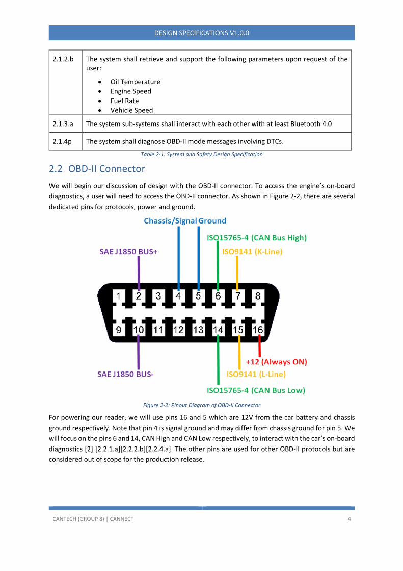
We will begin our discussion of design with the OBD-II connector. To access the engine’s on-board
diagnostics, a user will need to access the OBD-II connector. As shown in Figure 2-2, there are several
dedicated pins for protocols, power and ground.
Figure 2-2: Pinout Diagram of OBD-II Connector
For powering our reader, we will use pins 16 and 5 which are 12V from the car battery and chassis
ground respectively. Note that pin 4 is signal ground and may differ from chassis ground for pin 5. We
will focus on the pins 6 and 14, CAN High and CAN Low respectively, to interact with the car’s on-board
diagnostics [2] [2.2.1.a][2.2.2.b][2.2.4.a]. The other pins are used for other OBD-II protocols but are
considered out of scope for the production release.

CANTECH (GROUP 8) | CANNECT 5
DESIGN SPECIFICATIONS V1.0.0
Figure 2-3: Example of a OBD-II Diagnostic Port Location
In a car, a common location for the female OBD-II connector would be between the steering column
and the pedals as shown in Figure 2-3. The location of these OBD-II connectors depends on the car
manufacturer. Typically, OBD-II readers will connect to these physical connectors, either via extension
wires for use when the car is stationary or a compact form to allow the driver to operate the car while
the reader gathers data. For the purposes of this project, the hardware will be designed to
accommodate use of the reader during a car’s runtime which will necessitate reducing the size of the
reader in order not to interfere with a driver’s ability to operate the car [2.2.3.b].
Design Number
Design Description
2.2.1.a The reader shall connect to an OBD-II female port connector with an OBD-II male port connector.
2.2.2.b As depicted in Figure 2-2, the reader shall use the following pins of the OBD-II port for the following purposes:
• Pin 5 – Ground
• Pin 6 – CAN High
• Pin 14 – CAN Low
• Pin 16 – 12V Power
2.2.3.b The reader shall be enclosed in a closed, compact form that does not impede the operation of the vehicle.
2.2.4.a The reader shall interact with a CAN Bus system using the CAN High and CAN Low ports.
Table 2-2: OBD-II Connector Designs
Reader
Our reader will be the main hardware that will serve as a medium between the car’s CAN Bus system
and the smartphone app. It will connect to the female OBD-II connector physically and interact with
the smartphone via Bluetooth. During the alpha-phase, the focus of development will primarily be
validating and verifying this concept. When we transition into the beta-phase, the focus will shift into
optimising the reader’s hardware into a compact form that can be used while a user is driving.

CANTECH (GROUP 8) | CANNECT 6
DESIGN SPECIFICATIONS V1.0.0
Reader Design Specifications
In this section and sub-sections, we will outline the design points for various phases for the reader.
Note that the hardware of the reader will be finalised by the end of the beta-phase. These design
points, along with the rest of tables in this section and sub-sections, will be discussed through section
2.3 in greater detail.
Design Number
Design Description
2.3.1.a The reader shall have the following sub-systems:
• CAN Bus Controller
• Control Unit
• Bluetooth Module
2.3.2.b The reader shall have the following hardware components:
• MCP 2515 Module
• ESP32 Module
2.3.3.a The reader shall be reprogrammable.
2.3.9.b The reader shall support an internal data speed of no less than 1 Mb/s (megabits/s)
2.3.11.b The reader’s power consumption shall be no more than 1 AmpHour.
2.3.12.b The reader’s current draw shall be no more than 0.5A.
2.3.12.b The reader shall regulate 12V to appropriate voltages to their respective sub-systems.
Table 2-3: Reader Overview Design Specifications
Design Number
Design Description
2.3.8.a The reader shall have Bluetooth capability that supports at least Bluetooth 4.0.
2.3.10.a The reader’s Bluetooth module shall have a slave relationship to a smartphone.
Table 2-4: Reader Bluetooth Design Specifications
Design Number
Design Description
2.3.4.a The reader shall receive data frames matching a list of PIDs within the data segment as defined in ISO 15031-5.
2.3.5.a The reader shall identify data frames using a CAN ID.
CANTECH (GROUP 8) | CANNECT 7
DESIGN SPECIFICATIONS V1.0.0
2.3.6.b The reader shall change the list of PIDs in accordance to user’s request from the mobile app.
2.3.7.a The reader shall forward accepted data frames to the mobile app.
2.3.15b The reader shall follow ISO 15765-4 for the following OSI layers:
• Physical
• Data Link
• Network
• Transport
2.3.16b The reader shall follow ISO 14229-2 for the following OSI layers:
• Session
2.3.17b The reader shall perform data validation using the 15-bit CRC in the CAN frame.
2.3.18a The reader shall be able to receive CAN 2.0 A Standard Frame Formats as defined in ISO 15765-4.
2.3.19p The reader shall support reading of other OBD-II mode messages such those involving DTCs (ISO 15031-6).
Table 2-5: Reader CAN Bus Design Specifications
Design Number
Design Description
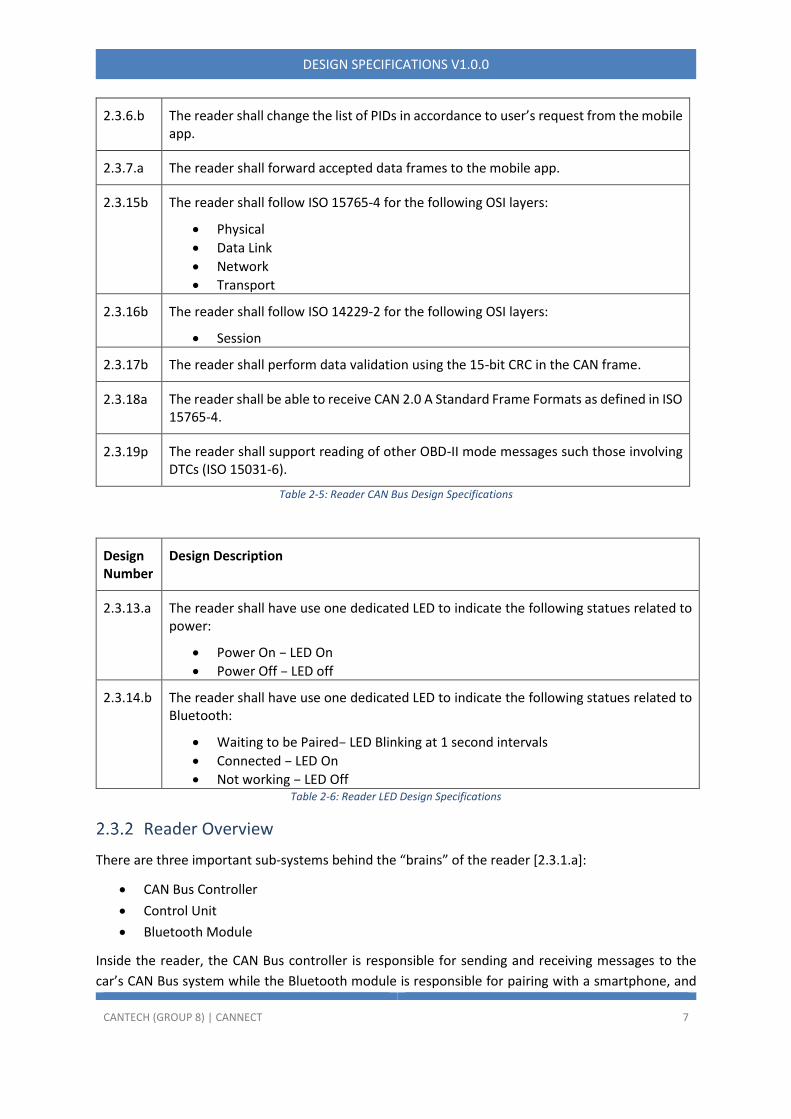
2.3.13.a The reader shall have use one dedicated LED to indicate the following statues related to power:
• Power On – LED On
• Power Off – LED off
2.3.14.b The reader shall have use one dedicated LED to indicate the following statues related to Bluetooth:
• Waiting to be Paired– LED Blinking at 1 second intervals
• Connected – LED On
• Not working – LED Off Table 2-6: Reader LED Design Specifications
Reader Overview
There are three important sub-systems behind the “brains” of the reader [2.3.1.a]:
• CAN Bus Controller
• Control Unit
• Bluetooth Module
Inside the reader, the CAN Bus controller is responsible for sending and receiving messages to the
car’s CAN Bus system while the Bluetooth module is responsible for pairing with a smartphone, and

CANTECH (GROUP 8) | CANNECT 8
DESIGN SPECIFICATIONS V1.0.0
facilitating communication to a smartphone app. The Control Unit ensures that both CAN Bus
controller and Bluetooth module can perform their tasks according to what the user wants. Since the
Control Unit interacts with both CAN Bus controller and Bluetooth module directly, deciding a Control
Unit is a crucial factor as the decision will influence the decisions of the other modules. This control
unit, especially during the production phase, allows us to make incremental changes via software if
needed.
We chose to use Bluetooth as the method to connect our reader to the smartphone as most
smartphones, especially Android phones, use at least Bluetooth 4.0 to facilitate wireless
communications over a short distance [2.3.8.a]. The technology is well understood and well used by
many systems, making it a straightforward solution. We opt for the reader to have a slave relationship
with the mobile app in order not to send unsolicited messages to the smartphone [2.3.10.a].
Note that the smartphone app will perform the role of interpretation of the CAN Bus messages as well
as the configuration of the reader. Therefore, the reader’s software will be simple. Further expansion
of features may be done if warranted but is unlikely to go beyond the mentioned tasks.
Alpha Phase
During the alpha phase, the focus on design is to build a working proof-of-concept prototype to
validate the feasibility of meeting the requirements outlined in the Requirements Specification
document. Therefore, our choices of the hardware components outlined in the previous section will
be focus on reusable components, ease of development and quick prototyping.
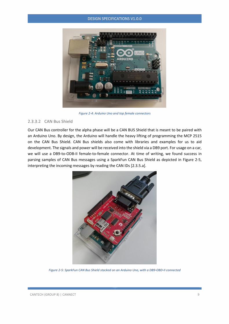
Arduino Uno
We opt for an Arduino Uno development board due to the ease of development, documentation,
community example and a variety of choices in choosing the other components for our reader.
Furthermore, we can simply pick other shields for the other two components and reuse them for other
different projects. By design, Arduino Unos allow multiple shields of different functionality to be
stacked on top of it, with the limiting factor being power consumption, GPIO ports and form factor. It
also allows easy debugging using an Arduino IDE and LED lights to indicate serial activity [2.3.13.a]. By
simply programming the Arduino Uno, we can control the functionality of the shields [2.3.3.a].
CANTECH (GROUP 8) | CANNECT 9
DESIGN SPECIFICATIONS V1.0.0
Figure 2-4: Arduino Uno and top female connectors
CAN Bus Shield
Our CAN Bus controller for the alpha phase will be a CAN BUS Shield that is meant to be paired with
an Arduino Uno. By design, the Arduino will handle the heavy lifting of programming the MCP 2515
on the CAN Bus Shield. CAN Bus shields also come with libraries and examples for us to aid
development. The signals and power will be received into the shield via a DB9 port. For usage on a car,
we will use a DB9-to-ODB-II female-to-female connector. At time of writing, we found success in
parsing samples of CAN Bus messages using a SparkFun CAN Bus Shield as depicted in Figure 2-5,
interpreting the incoming messages by reading the CAN IDs [2.3.5.a].
Figure 2-5: SparkFun CAN Bus Shield stacked on an Arduino Uno, with a DB9-OBD-II connected

CANTECH (GROUP 8) | CANNECT 10
DESIGN SPECIFICATIONS V1.0.0
Bluetooth Module
In order to communicate with a smartphone, we opt for a Bluetooth shield that is compatible with
Arduino Uno. Similar to CAN Bus shield, the core objective is to fulfill our requirements for the alpha
phase for a working prototype. Since these are Arduino shields, this Bluetooth module can be stacked
on top of an Arduino Uno. Like the CAN Bus shield, we will utilise the manufacturer’s provided libraries
to assist with development. In Figure 2-6, this BLE shield uses Bluetooth and connects to Android
smartphones that run Android 4.3 or above [1] as they both run at least Bluetooth 4.0 [2.3.8.a].
Figure 2-6: Seeed Studio's Bluetooth Shield
Alpha-phase Reader
The proposed reader prototype will have a similar design as in Figure 2-7, with the CAN Bus shield and
Bluetooth shield stacked on top of the Arduino Uno. Firmware will be loaded onto the Arduino Uno
which will program the respective shields to function as a reader. The actual software programmed
for the alpha-phase is only concerned with reading the CAN Bus system, based on several hard-coded
parameters selected, and passing the messages to the app via Bluetooth. In order to not pass garbage
messages, we will only pass messages that are from the list of parameters [2.3.4.a]; other types of
messages will be rejected [2.3.7.a]. For the alpha phase, it is sufficient to have this list hard coded.

CANTECH (GROUP 8) | CANNECT 11
DESIGN SPECIFICATIONS V1.0.0
Figure 2-7: Proposed Alpha Prototype without wires
Network Stack
To read the data, the reader will request and interpret data using the protocols implemented as part
of CANBUS and OBD-II. These standards include ISO 15765-4 across all lower layers, ISO 14229-2 on
the session layer, ISO 15031 parts 2, 5 and 6 on the presentation layer, and ISO 15031-5 on the
application layer [3]. Put together, they make up the network stack that will be implemented in
CANnect to read and interpret data from the car.

CANTECH (GROUP 8) | CANNECT 12
DESIGN SPECIFICATIONS V1.0.0
OSI Layer
Figure 2-8: OSI Layer Diagram of OBD-II. CANtech's focus is highlighted in red
As part of ISO 15765-4 and ISO 14229-2, these encompass all the necessary components to create a
connection, send data and close the connection to the reader. Note that ISO 15765-4 encompasses
the standards given in the alternative for the legislated OBD which are ISO 15765-2, 11898-1 and
11898-2, and makes up the CANBUS standard used for accessing emissions and diagnostic data from
an external tool.
To interpret the data transported, ISO 15031-5 and ISO 15031-6 are used to define many of the IDs
and diagnostic codes. The former is used to define OBD-II PIDs for many diagnostic and status
parameters while the latter defines the diagnostic trouble codes for troubleshooting. Given the
regulatory requirements surrounding them, many of the definitions given should be standardized
across vehicles and will be used to request and identify data in the messages.
Note that the SAE standards in the chart are reflected in the ISO 15031 series parts 2, 5 and 6. For
other data which are not listed in the standard, online research, exploratory testing and reverse
engineering can be used as a starting point to find the PID and data parameters.
Basic filtering and CRC validation of frames received on the reader side will be implemented, but the
interpretation and conversion into a user-accessible format will be performed on the phone
application. This was chosen as it offloads most of the work from the lower-powered Arduino device
to better read and process frames in a faster manner to keep up in real-time while leveraging the
greater computational power of a smartphone. As well, the phone app will also be more flexible in
terms of data processing and installing app updates which is easier for the end-user than updating the
firmware on the Reader.
CANTECH (GROUP 8) | CANNECT 13
DESIGN SPECIFICATIONS V1.0.0
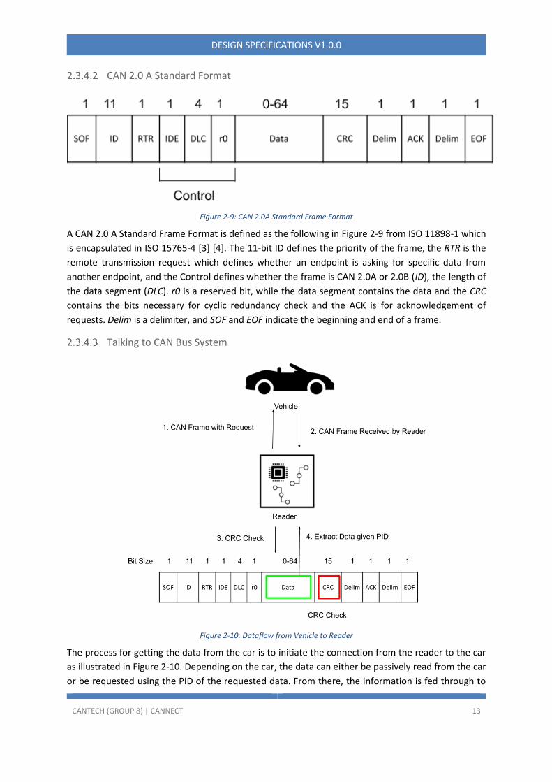
CAN 2.0 A Standard Format
Figure 2-9: CAN 2.0A Standard Frame Format
A CAN 2.0 A Standard Frame Format is defined as the following in Figure 2-9 from ISO 11898-1 which
is encapsulated in ISO 15765-4 [3] [4]. The 11-bit ID defines the priority of the frame, the RTR is the
remote transmission request which defines whether an endpoint is asking for specific data from
another endpoint, and the Control defines whether the frame is CAN 2.0A or 2.0B (ID), the length of
the data segment (DLC). r0 is a reserved bit, while the data segment contains the data and the CRC
contains the bits necessary for cyclic redundancy check and the ACK is for acknowledgement of
requests. Delim is a delimiter, and SOF and EOF indicate the beginning and end of a frame.
Talking to CAN Bus System
Figure 2-10: Dataflow from Vehicle to Reader
The process for getting the data from the car is to initiate the connection from the reader to the car
as illustrated in Figure 2-10. Depending on the car, the data can either be passively read from the car
or be requested using the PID of the requested data. From there, the information is fed through to
CANTECH (GROUP 8) | CANNECT 14
DESIGN SPECIFICATIONS V1.0.0
the reader which reads the CAN message and filters those that are specified by the user if given such
parameters. Then, data validation is performed, the message section is stripped and packaged as
required. Data processing and interpretation are performed on the phone application.
In terms of software, the reader will have few changes between the alpha-phase and beta-phase as
the reader’s software concentrates on reading the received frames and sending them to the app via
Bluetooth. In the alpha stage, the available PIDs that can be requested will be hard-coded. For the
beta-phase, the reader device will need to be flexible to request messages specified by the user.
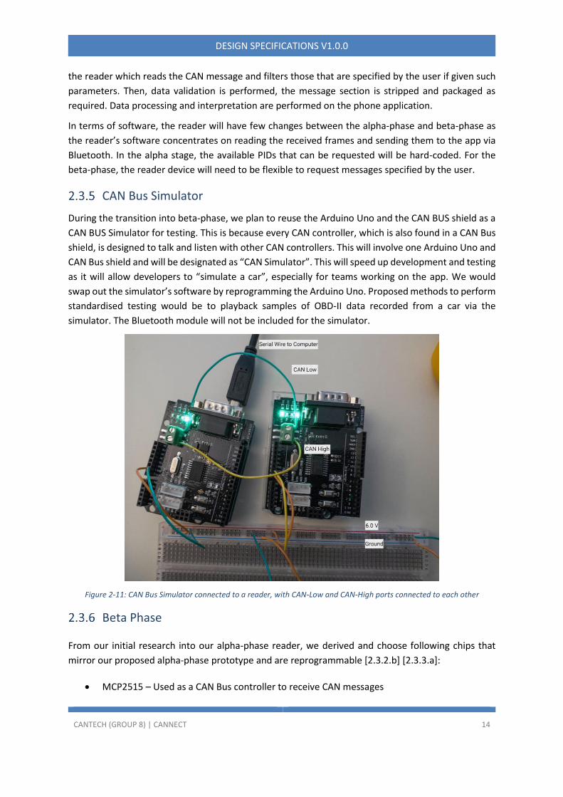
CAN Bus Simulator
During the transition into beta-phase, we plan to reuse the Arduino Uno and the CAN BUS shield as a
CAN BUS Simulator for testing. This is because every CAN controller, which is also found in a CAN Bus
shield, is designed to talk and listen with other CAN controllers. This will involve one Arduino Uno and
CAN Bus shield and will be designated as “CAN Simulator”. This will speed up development and testing
as it will allow developers to “simulate a car”, especially for teams working on the app. We would
swap out the simulator’s software by reprogramming the Arduino Uno. Proposed methods to perform
standardised testing would be to playback samples of OBD-II data recorded from a car via the
simulator. The Bluetooth module will not be included for the simulator.
Figure 2-11: CAN Bus Simulator connected to a reader, with CAN-Low and CAN-High ports connected to each other
Beta Phase
From our initial research into our alpha-phase reader, we derived and choose following chips that
mirror our proposed alpha-phase prototype and are reprogrammable [2.3.2.b] [2.3.3.a]:
• MCP2515 – Used as a CAN Bus controller to receive CAN messages
CANTECH (GROUP 8) | CANNECT 15
DESIGN SPECIFICATIONS V1.0.0
• TJA1050 – Used as a CAN Bus Transceiver to talk to the car’s CAN Bus system
• ESP32 – Used as both a Control Unit and a Bluetooth Module
Due to our research almost complete for the reader, at least for the hardware, it is unlikely that there
will be deviations between the proposed designs discussed in Table 2-6 and the implementation
demonstrated in December 2020.
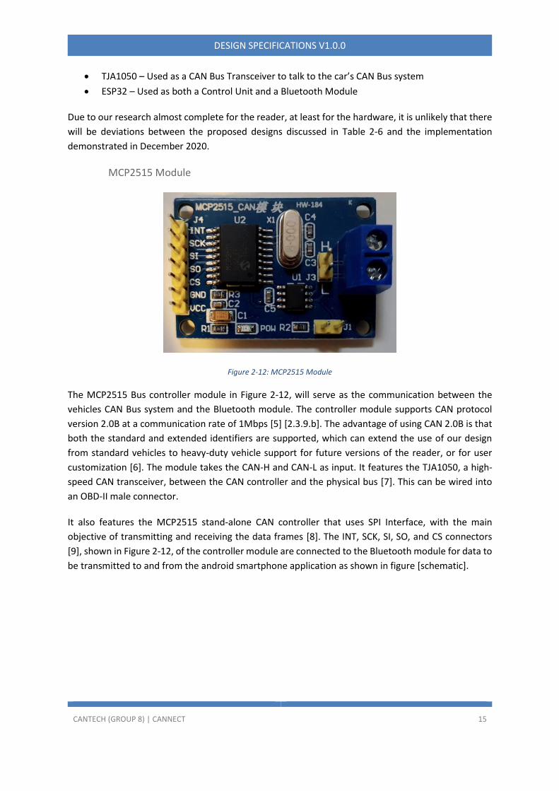
MCP2515 Module
Figure 2-12: MCP2515 Module
The MCP2515 Bus controller module in Figure 2-12, will serve as the communication between the
vehicles CAN Bus system and the Bluetooth module. The controller module supports CAN protocol
version 2.0B at a communication rate of 1Mbps [5] [2.3.9.b]. The advantage of using CAN 2.0B is that
both the standard and extended identifiers are supported, which can extend the use of our design
from standard vehicles to heavy-duty vehicle support for future versions of the reader, or for user
customization [6]. The module takes the CAN-H and CAN-L as input. It features the TJA1050, a high-
speed CAN transceiver, between the CAN controller and the physical bus [7]. This can be wired into
an OBD-II male connector.
It also features the MCP2515 stand-alone CAN controller that uses SPI Interface, with the main
objective of transmitting and receiving the data frames [8]. The INT, SCK, SI, SO, and CS connectors
[9], shown in Figure 2-12, of the controller module are connected to the Bluetooth module for data to
be transmitted to and from the android smartphone application as shown in figure [schematic].

CANTECH (GROUP 8) | CANNECT 16
DESIGN SPECIFICATIONS V1.0.0
ESP32 Module
Figure 2-13: ESP32 Module
The ESP32 module in Figure 2-13, will be utilized to provide the Bluetooth functionality between the
MCP2515 CAN controller module and the android smartphone, hosting our CANnect software
application. The ESP32 offers Wi-Fi, and Classic Bluetooth and Bluetooth Low Energy (BLE) support
and features capacitive touch sensor, SD card interface, Ethernet and high-speed SPI. [10] [11]. The
module for the basic version or our design will be implemented in Bluetooth Classic to exchange data
between the android smartphone and the MCP2515 CAN controller. Bluetooth Classic will be
implemented because although BLE has a lower power consumption, it is not ideal for exchanging
large amounts of data continuously [12]; practical transfer rate for Bluetooth Classic is roughly
2Mbits/s [13] [2.3.9.b]. The ESP32 pin connections are referenced in Figure 2-14. The inputs to this
module are the connectors from the MCP2515 module and an indicator LED to validate the Bluetooth
connection as shown in Figure 2-15 [2.3.14.b].

CANTECH (GROUP 8) | CANNECT 17
DESIGN SPECIFICATIONS V1.0.0
Figure 2-14: ESP32 Pinout Diagrams [14]
Module/ Components Power Supply Operating Current Operating Temperature Range
ESP32-WROOM-32 3.0V ~ 3.6 V 80 mA (average) -40 C ~ +85 C
MCP2515_CAN 5 V 5 mA -40 C ~ +85 C
MCP2515_CAN Components
MCP2515 2.7 ~ 5.5 V 10 mA (max) -40 C ~ +85 C
TJA1050 4.75 ~ 5.25 V 10 mA (max) -40C ~ +150 C
Table 2-7: Operating Characteristics
To ensure the correct voltages are connected to each component, a voltage regulator will be used. A
breakdown of the power supply, operating current and operating temperature ranges of the modules
are detailed in Table 2-7. The operating voltage range for the ESP32 module is between 3.0V to 3.6V,
and the voltage connected to the Vin pin (<12V) is converted to 3.3V by the on-board voltage regulator
[15]. The MCP2515 CAN controller module takes a 5V supply voltage. Thus, the voltage regulator 7805

CANTECH (GROUP 8) | CANNECT 18
DESIGN SPECIFICATIONS V1.0.0
will be selected to ensure a supply voltage of 5V for both the ESP32 module and the MCP2515 CAN
controller module [2.3.12.b]. The battery power from the vehicle will serve as the input voltage for
the voltage regulator.
Two indicator LEDs are incorporated into the encasing of the CANnect reader, one of which is used to
show the device is active and one that is used to show the active Bluetooth connection [2.3.13.a][
2.3.14.b]. The two connections are mapped out in Figure 2-15: Proposed Beta-phase Reader
Schematic. The selected LEDs are red and green in colour, 5mm, with a typical forward voltage of 2.0V
and rated forward current of 20mA [16] [17]. Resistors paired with the green (LED1) and red LED
(LED2) are 560𝛺 and 150𝛺 respectively, figure [schematic]. Resistances are calculated using the 𝑉 =
𝐼 𝑥 𝑅relationship in the Table 2-8 below:
Resistor Rvalue = (source voltage - diode forward voltage) / diode forward current
R1 R1 = 12V-2V/ 0.02 => 560 𝛺
R2 R2 = 5V-2V/ 0.02 => 150 𝛺
Table 2-8: Resistor Table

CANTECH (GROUP 8) | CANNECT 19
DESIGN SPECIFICATIONS V1.0.0
Figure 2-15: Proposed Beta-phase Reader Schematic
A well-designed product is one that promotes ease of use in the first interaction the user has with the
product [18]. The objective of the external hardware design is to be a compact enclosure of the above-
mentioned modules and electronic components. The CANnect reader should be compact and durable
enough to withstand regular use over its lifetime. There will be an indicator light to show the device
is powered on, as well as an indicator light to show that the Bluetooth connection is successful. There
will also be no external cable connector for the OBD-II port, which are featured in some CAN Bus
readers. Further details of the CANnect reader encasing can be referenced in Error! Reference source
not found..
We decided not to include a switch in the reader as our use cases are done with the assumption that
the car’s electronics are turned on and the engine is running. The user will know that their reader is
turned on using a LED that signifies that the reader is turned on. The user will also rely on a different
LED to indicate their Bluetooth connection to the reader.

CANTECH (GROUP 8) | CANNECT 20
DESIGN SPECIFICATIONS V1.0.0
Power Consumption
Because we did not include a switch, one may be concerned that our reader will drain the car’s battery
due to power consumption if the user does not remove it from the OBD-II connection. We are not
concerned as the reader does not have a significant power consumption and will justify this with the
proposed design characteristics.
For the sake of simplicity, we will assume that the final reader’s power consumption relies only on the
ESP32, MCP 2512 and two LEDs. We will also assume that the car battery supplies a steady DC voltage
of 12V and the reader will receive 12V. Finally, we will assume the reader will draw a steady current
that does not fluctuate. The ESP32 has an operating current of 80mA and the MCP2515 has an
operating current of 10mA. We assume that each of the two LEDs will shine its brightness with a
current of 20mA each. This gives the reader a total current draw of 130mA, an acceptable current
draw [2.3.12.b].
Car batteries are typically rated by Ampere-Hours. Since the voltage drawn by the reader will equal
the voltage supplied by the battery, this gives us the equation of 𝐶𝑢𝑟𝑟𝑒𝑛𝑡−𝐻𝑜𝑢𝑟𝑠 𝑜𝑓 𝐵𝑎𝑡𝑡𝑒𝑟𝑦
𝐶𝑢𝑟𝑟𝑒𝑛𝑡 𝑑𝑟𝑎𝑤 𝑓𝑟𝑜𝑚 𝑟𝑒𝑎𝑑𝑒𝑟=
𝑁𝑢𝑚𝑏𝑒𝑟 𝑜𝑓 𝐻𝑜𝑢𝑟𝑠 𝑡𝑜 𝑑𝑒𝑝𝑙𝑒𝑡𝑒 𝑡ℎ𝑒 𝑏𝑎𝑡𝑡𝑒𝑟𝑦. A typical car battery has an average power rating of
45AHr. This means our equation gives us 45 𝐴𝐻𝑟
130𝑚𝐴≈ 346ℎ𝑜𝑢𝑟𝑠. This means that a car’s battery will be
drained by our reader in about 14 days [2.3.11.b].
In reality, most modern cars’ electronics will turn off the supplied voltage to the OBD-II connector
when the key is not in the ignition. Furthermore, the reader will set each of its components to go into
“sleep mode” if it senses lack of activity from the user.
CAN Bus (Beta-Phase)
Many of the design specifications between alpha and beta on the reader side are similar. For the beta-
phase, the reader will be focused on making request to read specific messages via PIDs sent by the
mobile app rather than a list of hardcoded values. As well, a much more comprehensive set of PIDs
from ISO 15031-5 and DTCs from ISO 15031-6 will begin work in the beta stage. Non-standard PIDs by
a car manufacturer will also be implemented if they can be identified correctly through research
and/or exploratory testing. However, due to much uncertainty of how successful this endeavour will
be, these design specifications will be deferred to the production phase.
Mobile App Design
Majority of the development work throughout the alpha-phase and beta-phase will be focused on the
app, primarily its user interface. This is because the mobile app will be responsible for receiving raw
messages from the reader, processing the data and displaying human-readable information to the
user. The user will also interact with the entire CANnect system via the mobile app. Therefore, it is
crucial that our design specifications for the mobile app are clear and concise up front before
development work starts.
Since Android controls a 74.13% market share [19] and we want to appeal to the most people, we
decide that our mobile app will be developed for smartphones having the Android operating system
and have Bluetooth functionality. We chose to make Android 6.0 to be the minimum version as it

CANTECH (GROUP 8) | CANNECT 21
DESIGN SPECIFICATIONS V1.0.0
would make it accessible to most users while having the necessary permissions we want. In particular,
we want to utilise the user-granted permission model that is introduced in Android 6.0 [20] and
Android 6.0 apps can be run by ~84.9% of Android users as of April 20, 2020 [21][2.4.1.a]. It also
supports Bluetooth 4.0 [ 2.4.2.a]. The design points are outlined in Table 2-9: Mobile App General
Requirements. Because our development for the mobile app will be a continually progress, our design
specifications for the general requirements must be met by the end of alpha phase as they will be
unchanged throughout the entire development cycle.
Design Number
Design Description
2.4.1.a The smartphone shall support Android 6.0 and newer.
2.4.2.a The smartphone shall have at least Bluetooth 4.0.
Table 2-9: Mobile App General Requirements
We will focus on developing a native Android app using Java through using the Android Studio SDK as
it is the easiest developing environment to work with. It also provides debugging tools and visual
layout editors to assist with development [22].
Mobile Software Design Specifications
Specific design specifications for the alpha and beta phase are outlined in Table 2-10.
Design Number
Design Description
2.4.3.a The software application shall show a list of parameters for the user to choose and display.
2.4.4.a The software application shall update the values being displayed upon receiving new data from the reader.
2.4.5.a The software application’s Bluetooth shall pair with the reader, forming a master relationship.
2.4.6.a The software application shall request for an update of data from the reader at most every 5 seconds.
2.4.7.a The software application shall use a subset of ISO 15031-5 for PIDs to request, receive and interpret the data.
2.4.8.a The software application shall validate the PID received within the OBD-II message against the requested PID, and the list of valid PIDs.
2.4.9.b The software application shall use ISO 15031-5 and ISO 15031-6 as well as custom manufacturer-specific standards if identified for PIDs and DTCs to request, receive and interpret.
CANTECH (GROUP 8) | CANNECT 22
DESIGN SPECIFICATIONS V1.0.0
2.4.10.b The software application shall be able to request a wider range of PIDs or parameters as defined by the user or within the application.
Table 2-10: Mobile Software Design Specifications
Main
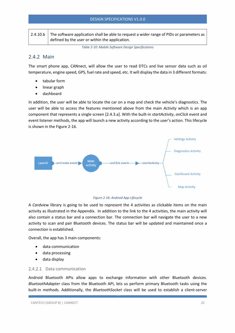
The smart phone app, CANnect, will allow the user to read DTCs and live sensor data such as oil
temperature, engine speed, GPS, fuel rate and speed, etc. It will display the data in 3 different formats:
• tabular form
• linear graph
• dashboard
In addition, the user will be able to locate the car on a map and check the vehicle's diagnostics. The
user will be able to access the features mentioned above from the main Activity which is an app
component that represents a single screen [2.4.3.a]. With the built-in startActivity, onClick event and
event listener methods, the app will launch a new activity according to the user’s action. This lifecycle
is shown in the Figure 2-16.
Figure 2-16: Android App Lifecycle
A Cardview library is going to be used to represent the 4 activities as clickable items on the main
activity as illustrated in the Appendix. In addition to the link to the 4 activities, the main activity will
also contain a status bar and a connection bar. The connection bar will navigate the user to a new
activity to scan and pair Bluetooth devices. The status bar will be updated and maintained once a
connection is established.
Overall, the app has 3 main components:
• data communication
• data processing
• data display
Data communication
Android Bluetooth APIs allow apps to exchange information with other Bluetooth devices.
BluetoothAdapter class from the Bluetooth API, lets us perform primary Bluetooth tasks using the
built-in methods. Additionally, the BluetoothSocket class will be used to establish a client-server

CANTECH (GROUP 8) | CANNECT 23
DESIGN SPECIFICATIONS V1.0.0
communication between the smartphone and the Bluetooth device, smartphone being the client. This
corresponds to the smartphone being the master in relation to the reader’s Bluetooth
module[2.4.5.a]. The methods that will be used are shown in the Table 2-11 with their purpose of use.
Methods Description
BluetoothAdapter::getDefaultAdapter() To access the local Bluetooth adapter
BluetoothAdapter::startDiscovery() To query a list of devices
BluetoothAdapter::isenabled() To check if Bluetooth is enabled
BluetoothAdapter::getRemoteDevice() To access the remote Bluetooth adapter
BluetoothSocket
::createRfcommSocketToServiceRecord()
To initiate a secure communication
BluetoothSocket::getInputStream() To receive bytes in serial
Table 2-11: Bluetooth API Methods
Data processing
When the messages are received by the smartphone app, it will need to be interpreted before any
useful information can be displayed to the user. This involves understanding and converting the OBD-
II messages into human-readable text and its given context.
Using the ISO standards as defined within the network stack in section 2.3.4, provides a standardized
method of requesting, identifying and parsing data. ISO 15031-5 provides the OBD-II Parameter
Identification Numbers (PIDs) which are reflected from SAE J1979-DA while ISO 15031-6 defines the
diagnostic trouble codes (DTC) are from SAE J2012-DA.
For additional PIDs that may not be supported on a specific car and/or car manufacturer, these may
be added given proper exploratory testing and available resources.

CANTECH (GROUP 8) | CANNECT 24
DESIGN SPECIFICATIONS V1.0.0
Figure 2-17: Receiving and Processing Data from Reader to Mobile App
On the phone side as shown in Figure 2-17, the application indicates the request for data using the
PIDs in ISO 15031-5 to the reader which creates the CAN frame necessary to send to the car. Once it
is processed on the reader side and is ready to transmit, the data segment of the CAN 2.0A Standard
Frame containing the entire OBD-II message frame is sent to the phone via Bluetooth. Upon receiving
the data, the phone will verify that the correct PID is received relative to the requested data and then
is calculated accordingly to a decimal or another appropriate value which is displayed on-screen in a
user-friendly manner. If requested by the user, the data can be compiled into a more useful format
such as a graph or a data log.
The alpha stage for data processing is focused on a smaller subset of standardized PIDs from ISO
15031-5 which includes basic information such as engine RPM and fuel levels. This will be used as the
launch point for the beta phase to support additional standardized PIDs as well as DTCs from ISO
15031-6 and non-standard manufacturer specific PIDs.
OBD-II Message Frame
OBD-II message structure is made up of eight segments which starts with the 11-bit identifier to
distinguish between request and response messages. The next section indicates the size of the
message data in bytes, while the mode indicates different diagnostic services. There are 10 different
modes ranging from showing the status, showing the DTC and requesting vehicle data. The next
section, PID, is used to identify the status of various vehicle components or states such as speed,
engine RPM and fuel levels [2.4.8.a]. These PIDs are defined in ISO 15031-5. The remaining data length
is used to calculate the value of requested information. These formulas will be implemented in the
app software to decode the requested message for readers in real-time [2.4.7.a][2.4.9.b].
Identifier #bytes Mode PID A B C D Unused
Figure 2-18: OBD-II Message Format
The following is the one example of the OBD-II message:
7E8 03 41 0D 32 AA BB CC DD
0x7E8 in the above message is the identifier which responds to the request made by the user. And the
data length 0x03 informs that only the following 3 bytes will be considered as data. The hexadecimal

CANTECH (GROUP 8) | CANNECT 25
DESIGN SPECIFICATIONS V1.0.0
number 0x41 represents the response message in mode 01. Typically, the hexadecimal number will
be from 0x01-0x0A for request messages, but the 0 is replaced by 4 in response messages. The next
hexadecimal number 0x0D is the standard PID that represents the vehicle speed. And the last valid
field is hexadecimal 0x32 which represents 50 in decimal numbers. The remaining fields are not used
since the data length is only 3 bytes.
Data display
The main focus of this component is to be able to display the vehicle’s data to the user in a safe
manner. CANnect mobile app shall use simple design to minimize driver distraction. For this reason,
we will provide 3 different display formats which the users can choose to use based on their
conditions. Each method provides a safer solution that the other methods lack. The app’s tabular form
shall not display animated elements. The app’s line graph shall not display data in text-heavy format.
The app’s dashboard shall not rely on user interaction while displaying information. The
MPAndroidChart library will be utilized to display the data in real-time on a line graph. We will aim to
refresh the values frequently by asking for an update at most every 5 seconds and refreshing the data
shown as soon as possible[2.4.4.a ][2.4.6.a].
Classes
Each activity will have its own business logic and, to separate the UI from the logic, we are going to
use Java classes. For each activity, a new Java class will be implemented. The information
corresponding to each class is illustrated in the class UML diagram below. Event listeners will be
created in which will call the methods.
Figure 2-19: UML Class Diagram of Mobile App Screens
3 Conclusion
The principal design of CANnect is its open-sourced nature made up of a reader powered by an
Arduino Uno with C++ code and an Android smartphone app with a Bluetooth tether. By linking these
two main sub-systems to a car’s on-board diagnostic system via CANBUS and OBD-II and their related
standards, this enables data to be extracted by the reader and interpreted by the phone app. The
phone app will implement a subset of parameters from the car in the initial alpha stage for basic

CANTECH (GROUP 8) | CANNECT 26
DESIGN SPECIFICATIONS V1.0.0
functionality and interpretation with more information being made available in the beta stage. The
design of the phone application code is given in the UML diagrams.
With CANnect and each component working together, these pieces will work together to provide
information in a user-friendly manner to better inform users who are looking to be in touch with their
car’s health.
The design requirements defined in this document relate to the Reader and the phone application.
For more information about design intractability of CANnect, the User Interface and Appearance
Design document covers this. The Alpha stage is intended to be completed by August 2020 and the
Beta stage by December 2020.
CANTECH (GROUP 8) | CANNECT 27
DESIGN SPECIFICATIONS V1.0.0
4 References
[1] "Bluetooth 4.0 Low Energy-BLE Shield v2.1," Seeed Technology Co. Ltd., 2020. [Online]. Available:
https://www.seeedstudio.com/Bluetooth-4-0-Low-Energy-BLE-Shield-v2-1-p-1995.html.
[Accessed 09 July 2020].
[2] Components101, "ODB-II Connector," 2020. [Online]. Available:
https://components101.com/connectors/obd2. [Accessed 02 June 2020].
[3] "ISO 15765-4:2016(en) - Road vehicles — Diagnostic communication over Controller Area
Network (DoCAN) — Part 4: Requirements for emissions-related systems," International
Standards Organisation, 2016. [Online]. Available:
https://www.iso.org/obp/ui/#iso:std:iso:15765:-4:ed-3:v1:en. [Accessed 14 June 2020].
[4] S. Corrigan, "Introduction to the Controller Area Network (CAN)," Texas Instruments, May 2016.
[Online]. Available: https://www.ti.com/lit/an/sloa101b/sloa101b.pdf. [Accessed 17 June 2020].
[5] Ravi, "Arduino MCP2515 CAN Bus Interface Tutorial," 23 August 2018. [Online]. Available:
https://www.electronicshub.org/arduino-mcp2515-can-bus-tutorial/. [Accessed 09 July 2020].
[6] CSS Electronics, "OBD2 Explained - A Simple Intro (2020)," CSS Electronics, 2020. [Online].
Available: https://www.csselectronics.com/screen/page/simple-intro-obd2-explained.
[Accessed 10 June 2020].
[7] Philips Semiconductors, "TJA1050 Datasheet," Philips Semiconductors, 22 October 2003.
[Online]. Available: https://www.nxp.com/docs/en/data-sheet/TJA1050.pdf. [Accessed 08 July
2020].
[8] Microchip, "MCP2515 Datasheet," Microchip Technology Inc., 15 August 2018. [Online].
Available: http://ww1.microchip.com/downloads/en/DeviceDoc/MCP2515-Stand-Alone-CAN-
Controller-with-SPI-20001801J.pdf. [Accessed 06 July 2020].
[9] Copper Hill, "MCP2515 CAN Bus Breakout Board With SPI Interface," Copper Hill Technologies,
2020. [Online]. Available: https://copperhilltech.com/mcp2515-can-bus-breakout-board-with-
spi-interface/. [Accessed 11 July 2020].
[10
]
Espressif Systems, "ESP-WROOM-32 Datasheet," Espressif Systems, September 2019. [Online].
Available: https://www.espressif.com/sites/default/files/documentation/esp32-wroom-
32_datasheet_en.pdf. [Accessed 04 July 2020].
[11
]
Joy-IT, "NODEMCU ESP32," Joy-IT, 2020. [Online]. Available: https://joy-it.net/en/products/SBC-
NodeMCU-ESP32. [Accessed 16 July 2020].
[12
]
B. Ray, "Bluetooth Vs. Bluetooth Low Energy: What's The Difference?," Link Labs, 01 November
2015. [Online]. Available: https://www.link-labs.com/blog/bluetooth-vs-bluetooth-low-energy.
[Accessed 03 July 2020].
[13
]
N. Pradhan, "Classic Bluetooth vs Bluetooth Low Energy - A Round by Round Battle," Symmetry
Electronics, 24 September 2014. [Online]. Available:

CANTECH (GROUP 8) | CANNECT 28
DESIGN SPECIFICATIONS V1.0.0
https://www.semiconductorstore.com/blog/2014/Classic-Bluetooth-vs-Bluetooth-Low-Energy-
A-Round-by-Round-Battle/860/. [Accessed 14 July 2020].
[14
]
Random Nerd Tutorials, "ESP32 Pinout Reference: Which GPIO pins should you use?," Random
Nerd Tutorials, 2020. [Online]. Available: https://randomnerdtutorials.com/esp32-pinout-
reference-gpios/. [Accessed 09 July 2020].
[15
]
Tech Explorations, "Introduction to the ESP32" series - ESP32 Dev Kit Power Options," Tech
Explorations, 2020. [Online]. Available:
https://techexplorations.com/guides/esp32/begin/power/. [Accessed 08 July 2020].
[16
]
SparkFun Electronics, "LED - Basic Red 5mm," SparkFun Electronics, [Online]. Available:
https://www.sparkfun.com/products/9590. [Accessed 12 July 2020].
[17
]
SparkFun Electronics, "LED - Basic Green 5mm," SparkFun Electronics, [Online]. Available:
https://www.sparkfun.com/products/9592. [Accessed 09 July 2020].
[18
]
D. A. Norman, The Design of Everyday Things, Revised ed., New York, New York: Basic Books,
2013.
[19
]
S. O'Dea, "Mobile operating systems' market share worldwide from January 2012 to December
2019," Statista, 28 February 2020. [Online]. Available:
https://www.statista.com/statistics/272698/global-market-share-held-by-mobile-operating-
systems-since-2009/. [Accessed 12 July 2020].
[20
]
Android Developers, "Permissions overview - Documents," Google Developers, 07 May 2020.
[Online]. Available:
https://developer.android.com/guide/topics/permissions/overview?fbclid=IwAR1xIPp5rllsxDac
QlafuVCIpYbj3-rnuLjQ5v-OHGiEFxQsE7cSVACILPc#permissions. [Accessed 12 July 2020].
[21
]
M. Rahman, "Android Version Distribution statistics will now only be available in Android Studio,"
XDA Developers, 10 April 2020. [Online]. Available: https://www.xda-developers.com/android-
version-distribution-statistics-android-studio/?fbclid=IwAR1Emamn9LtzyaFEsV0ydcYu5SKFJFV-
u-vOE8iQqDLj9TBf0KU_-NKEupk. [Accessed 12 July 2020].
[22
]
Google Developers, "Android Studio," Google, [Online]. Available:
https://developer.android.com/studio/index.html. [Accessed 05 July 2020].
[23
]
Tubik Studio, "Mobile UI Design: Basic Types of Screens.," Medium, 19 July 2017. [Online].
Available: https://uxplanet.org/mobile-ui-design-basic-types-of-screens-aa1857e31339.
[Accessed 09 July 2020].
[24
]
J. Kyes, "What is GPS?," Geotab Inc., 22 May 2020. [Online]. Available:
https://www.geotab.com/blog/what-is-gps/. [Accessed 09 July 2020].
[25
]
P. Laja, "10 Useful Findings About How People View Websites," 23 Feb 2020. [Online]. Available:
https://cxl.com/blog/10-useful-findings-about-how-people-view-websites/. [Accessed 13 July
2020].
[26
]
International Organization for Standardization & International Electrotechnical Commission,
"ISO/IEC TR 11580:2007(en) Information technology — Framework for describing user interface
objects, actions and attributes," International Organization for Standardization, 2007. [Online].
CANTECH (GROUP 8) | CANNECT 29
DESIGN SPECIFICATIONS V1.0.0
Available: https://www.iso.org/obp/ui/#iso:std:iso-iec:tr:11580:ed-1:v1:en. [Accessed 13 July
2020].
[27
]
A. Kanwal, "Espresso Android UI Testing," Medium, 22 April 2018. [Online]. Available:
https://medium.com/@aleesha/espresso-android-ui-testing-c6d696956dc9. [Accessed 13 July
2020].

CANTECH (GROUP 8) | CANNECT 30
DESIGN SPECIFICATIONS V1.0.0
5 Appendix A: User Interface and Appearance Design
The purpose of the user interface (UI) and appearance design introduces how our product CANnect
interacts with the users and makes sure that users can easily understand how to use our product
through the UI with no difficulties. The concept and theory behind the user interface design will also
be explained to support our UI design.
As a scope of this appendix, we start with the graphical representation to illustrate the device
appearance and the schematics of the CANnect Reader and mobile app UI. Our proposed UI will be
supported with the user analysis and technical analysis. The user analysis is performed to support the
schematics in the user perspective while the technical analysis entails 7 concepts of UI interaction
proposed by Don Norman in The Design of Everyday Things. Engineering standard is introduced to
ensure that our proposed UI follows the standard. Finally, the analytical and empirical usability testing
are proposed to ensure the bug free and high-quality UI.
Graphical Representation
The two main subsystems of CANnect are the CANnect reader and the supporting software
application. The reader and application are designed to be simple and intuitive. With user analysis,
constraints and engineering standards in mind, the finalized concept designs for both are detailed
below and shown in Figure 5-1, and Figure 5-2 respectively.
CANnect Reader Appearance
During the alpha-phase, the reader will have limited user interface beyond the LED lights available on
the Arduino Uno and shields that indicate that it is sending and receiving data. This lack of user
interface is acceptable as the only users that will operate them are the developers that have a
complete understanding of the system.
In preparation for the beta-phase however, the reader will undergo development to improve its user
interface for potential customers. Because we want our reader to be used during a normal operation
of a car, our reader must be compact and will not interfere with the driver’s ability to operate their
vehicle. This will take the form of enclosing the reader in a plastic shell that is small enough not to
impede the driver’s legs and feet.
The CANnect reader will feature two LEDs that indicate the status of the reader. Each LED informs the
user of the states of the reader. The power LED turns on when the reader is powered on and is not in
sleep mode. If the reader does not receive power, the power LED turns off. The Bluetooth LED starts
blinking on and off at a one second interval to indicate it is searching for a device to pair. If the
Bluetooth LED stays constant, it means that the reader is actively paired to a device. Grips are added
for better handling of the reader and preventing accidental slippage. The cube-shaped encasing,
protects the CAN Bus controller module, Bluetooth module, and electrical components inside, and
rounded edges offer protection should the device drop on its edge. The proposed design for the beta
and production phase prototype are shown in Figure 5-1.

CANTECH (GROUP 8) | CANNECT 31
DESIGN SPECIFICATIONS V1.0.0
Figure 5-1: Device sketch and concept color mapping of front view (left) and back view (right) of CANnect reader including grip, company labels and indicator lights
Mobile App UI
The following Figure 5-2 shows the graphical representation of the mobile app UI. The Main Menu
consists of 4 buttons and the users can easily tap one of them to go further on the next screen. The
“Press to Connect/Disconnect” button and the connection status are also placed in the same screen.
The settings can be the screen where the users can modify the app configuration however they want
and the diagnostics screen is where the user who wants to run the diagnostics test on the selected
PID from the menu. The user can press the button “Press to Run Test” and the diagnostics result will
be in the table form. The dashboard provides the visualization with the list of parameters in the tabs,
and finally we propose to have a map feature with the GPS toggle button ON/OFF.

CANTECH (GROUP 8) | CANNECT 32
DESIGN SPECIFICATIONS V1.0.0
Figure 5-2: Mockups of App Front-end
User Analysis
The user analysis provides an explanation of how to use our product from the interaction with the
hardware and the mobile app UI while the analysis is performed from the perspective of users. Our
target audience are users who are car enthusiasts, and tend to have a higher knowledge of cars than
the average person, but also users who want to analyze or conduct maintenance of their vehicles. The
open source aspect of CANtech opens up the opportunity to work with car manufactures to offer
maintenance support for their customers, or promote development research through the use of our
product. It is also meant to foster a community of users with an interest in or area expertise in vehicles,
looking to expand on or develop applications based on our CANnect product.
The CANnect reader features a standard OBD-II connector, indicator lights showing that the device is
turned on and that Bluetooth connection is working, and grips on either side of the reader. The user
should know the location of the OBD-II standard connector on their vehicle as well as compatibility
with their vehicle before use. The first-use interaction with the reader involves the user simply
connecting the CANnect reader to the OBD-II port in their vehicle and establishing a Bluetooth
connection with a compatible smartphone device.

CANTECH (GROUP 8) | CANNECT 33
DESIGN SPECIFICATIONS V1.0.0
For the software application, the text information from each item in the UI informs the user what
action they can make. As you can see from the Figure 5-3, the text content of “Press to Connect” from
the button with the Bluetooth symbol in the Main Menu is self-explanatory to the user that they would
know pressing this will establish the Bluetooth connection. The same principle applies to all any other
text content from each item such as the 4 buttons from the Main Menu, list of items in the menu, and
finally title from the header.
Figure 5-3: Bluetooth Connection Button on Main Menu
Technical Analysis
The technical analysis will support our UI and appearance design based on the “Seven Elements of UI
Interaction” from Don Norman’s Principal [1]. This analysis is performed to support our design from
the technical perspective following Don Norman’s Principal.
Discoverability
The concept states that “It is possible to determine what actions are possible and the current state
of the device”.
The CANnect reader follows the concept of Discoverability since the two LED indicate the current
status of the reader device. The power LED represents the current status of power and it can indiates
the next possible action if you want to turn ON or OFF. Similarly for the Bluetooth LED, blinking LED or
LED that stays ON continuously indicates the different status as searching for the device to be paired
or the status of established connection respectively. Again, each status determines the next possible
actions since if the LED is blinking, you will have to pair the Android device within the Bluetooth range
or if the LED stays constant, you can start interact with the mobile UI as the Bluetooth connection
establishes.
As for the mobile app UI, there are primarily two functionalities in our UI that follow the concept of
Discoverability. Firstly, each screen has a title name; for example, “Dashboard” can inform the user of
the current state of the application. Without this title, the user will be confused with the current state
of where they are and they may go back and forth to identify their current state. From the Main Menu,
the Bluetooth connection status is shown to inform the user if the device is connected with Bluetooth
or not, which is also the current status of the device. Secondly, the list of items provides the user what
actions are available to be made. For example from the dashboard, the list of tabs are shown so that
the user is informed of what options are available for actions as to visualize and this also applies to
the list of items in the settings and diagnostics menus.
Feedback
The concept of Feedback “There is full and continuous information about the results of actions and
the current state of the product or service. After an action has been executed, it is easy to determine
the new state.” is also followed.

CANTECH (GROUP 8) | CANNECT 34
DESIGN SPECIFICATIONS V1.0.0
The concept of Feedback applied on CANnect reader is similar to the Discoverability in that both power
and Bluetooth LED is the full and continuous information as a result of actions made. Powering the
Reader will result in a new state as power ON, which is easy to be interpreted by the LED light up.
Action of connecting the Bluetooth from the mobile app UI after bringing the Android device near the
Reader will result in a new state that the connection is established. Again, this new status is easy to
be interpreted by the Bluetooth LED that stays constantly ON.
As for the mobile app UI, from the Main Menu, the Bluetooth connection status is the full and
continuous information as a result of the action the user makes and the connection status is the
information that notifies the user the current status of the device as also mentioned in the
Discoverability concept. Once the user presses the “Press to Disconnect” or “Press to Connect” button,
the connection status is shown as “Disconnected” or “Connected” respectively, and this result is easy
for the user to determine the new status. Similarly for the toggle button on the map screen, tapping
this button will toggle to ON or OFF, which is the continuous information as a result of the action made
and informs the user the current status of the map. The resulting status after the executed action is
also to be determined as a new state since it only toggles from OFF to ON or ON to OFF. If the status
is ON, the user can know their location on the map but if the status is OFF, they cannot know their
location.
Conceptual Model
The Conceptual Model states that “The design projects all the information needed to create a good
conceptual model of the system, leading to understanding and a feeling of control. The conceptual
model enhances both discoverability and evaluation of results.”.
The design of the CANnect reader is very intuitive. The OBD-II connector is a specific standard across
vehicles that will be familiar to our users. As soon as the Reader device is plugged in and the Power
LED lights up as ON, blinking Bluetooth LED will search for the device to be paired and the user should
be able to establish the connection from the mobile app UI. Once the Bluetooth LED stays constantly
ON, the user now can interact with the mobile app UI and they take the desired actions from the Main
Menu. This whole process of the user interacting with the both Reader and mobile UI is our conceptual
model which makes the user feel control of the entire system. Also, this model enhances the enhances
the Discoverability concept since the user activity flow from Reader to mobile app UI simultaneously
follows the concept of Discoverability (each object in both UI follows this concept presented above)
while evaluating the resulting states throughout this activity flow.
Affordances
The concept of Affordances states that “The proper affordances exist to make the desired actions
possible”.
CANnect reader has male connector as can be seen in the design schematics from the figure 10-1 that
should fit well with the car with the female port. This allows the user to perform the desired action,
which is powering the reader ON. We propose that our reader follows the concept of Affordances as
there is no any hindrance in the reader shape design.

CANTECH (GROUP 8) | CANNECT 35
DESIGN SPECIFICATIONS V1.0.0
The overall mobile app UI system also follows this concept since there is no hindrance or contraction
of features that exists to prevent the user’s actions on the UI and the resulting state on the UI will
always be reached. For example, any button, toggle button, list of tabs, and list of items in a menu
shown in Figure 5-2 always provides the possible actions to the user. To support this, the location and
layout of the item such as button and the font size of the text provides enough information to the user
that they can immediately know where the action can be made and they can interpret what resulting
states the actions will bring from the text. As an one example, the location and the font size of text
from the button “Press to Disconnect” as shown in Figure 5-3 can let the user know where this button
is and what action is available from this button.
Signifiers
This concept states that “Effective use of signifiers ensures discoverability and that the feedback is
well communicated and intelligible.”.
Our signifiers in the Reader are both the power and Bluetooth LEDs. The user will be able to learn
quickly that the power LED will be the status of power ON/OFF and this signifier ensures the concept
of Discoverability and Feedback presented above. Bluetooth LED is also a signifier that the user will be
able to learn quickly represents the status of Bluetooth connection and again this follows the both
concept of Discoverability and Feedback aforementioned above.
The overall mobile UI follows this concept, especially the Main Menu. One example could be that from
Figure 5-4, the Bluetooth symbol which is commonly known among people indicates that the action is
associated with the Bluetooth so that the user can identify that pressing this button will result in the
connection with Bluetooth. This ensures the aforementioned concept of Discoverability since the
Bluetooth signifier is integrated in the button. Also, 4 categories of buttons in the same screen also
have signifiers as they have each associated commonly known symbols. For example, the settings
button uses the symbol of gear, the diagnostics button uses the wrench symbol and so on as signifiers.
Figure 5-4: Categories of Button on Main Menu

CANTECH (GROUP 8) | CANNECT 36
DESIGN SPECIFICATIONS V1.0.0
Mappings
This concept states that “The relationship between controls and their actions follows the principles of good mapping, enhanced as much as possible through spatial layout and temporal contiguity.”.
Our CANnect reader schematic design is referenced in the specification document. For the mapping
of internal modules, pin connections are clearly defined with 1 to 1, input to output mapping. For the
open source use of the hardware module, various general purpose pins on the modules can be
reformatted to introduce a new functionality the user may want to add. Similarly, user interaction
with the CANnect reader involves one action: plug in the reader and the device is powered on. Connect
the smartphone to the reader via Bluetooth, and the vehicle system data can now be accessed by the
user on the mobile app. Send a request to run a specific diagnostic test and receive results of the
specified test on the application dashboard.
All the screens in our mobile UI start with the title on the top with the “go back” functionality signified
as the left arrow button on the left side of the title and then come with the content below. The user
can always make sure that they are on the correct screen by looking at the title and if not they can
immediately go back by pressing the left arrow button. If the screen is what they are looking for, they
can look for the content after the title and this time flow is minimal and the user experience is efficient
since we believe that people will look things from top to bottom and this is also mentioned by the P.
Laja [2] that people read in “F-patterns”, meaning that people read things from top to bottom. This
also means that people read things from left to right, so we placed some items on the left side to make
the user experience efficient. For example, we placed the text content in a list of menu left hand side.
Constraints
Constraints states that “Providing physical, logical, semantic, and cultural constraints guides actions
and eases interpretation.”.
The CANnect reader dimensions are based on the size constraints of the internal modules, OBD-II
standard connector and other electrical components being used. The average sizing data of the
CANnect reader components are shown in Table 5-1. The encasing is thus determined to be 50 x 30 x
26 mm, with the modules arranged according to these length, height and width constrictions, and a
2mm plastic thickness on each side of the reader. A schematic of the CANnect reader views is shown
in Figure 5-5.
Device/ Component Size (L x W x H)
MCP2515_CAN 41.00 x 24.00 x 14.00 mm
ESP32 26.00 x 48.00 x 11.50 mm
OBD-II Standard Connector 15.30 x 41.20 x 19.05 mm
Table 5-1: The average size of modules and components of the CANnect reader [6][7][8]

CANTECH (GROUP 8) | CANNECT 37
DESIGN SPECIFICATIONS V1.0.0
Figure 5-5: Proposed Reader Shell Diagram
For the mobile app UI, there is a high constraint on the system since the only actions they can do are
as follows:
• Press the button
• Select the item from the menu or tabs
• Press “Go back” button to go back
• Scroll the items from the menu
The app UI is intended for read-only interaction with the car, so there should not be too many freedom
of actions on the UI to make users confused. We believe that the high constraint on the read-only
interface makes the users guides the next possible actions smooth and the interpretation will be easy.
Engineering Standards
Our product CANnect follows the following engineering standards for our proposed user interface.
ISO 9241-11:2018
CANnect reader follows this standard that defines a framework for understanding the concept of
usability of an interactive system used by people [3]. CANnect reader follows all the items in the
usability list defined in this standard but we especially would like to highlight that our device follows
the usability in that the system or product can be used by the targeted audience of users with high
satisfaction [3]. CANnect reader falls under this concept since our target audience is those who have
already knowledge in related automotive technologies and we ensure the high usability of our

CANTECH (GROUP 8) | CANNECT 38
DESIGN SPECIFICATIONS V1.0.0
product, which was analyzed in the user analysis and technical analysis. We ensure our product is safe,
useful in the context of use to connect to the car, effective, and efficient.
ISO/IEC TR 11580:2007
Our mobile app UI follows this standard and this code defines the format of name and properties of
UI objects, actions, and attributes, and they are standardized as a basis [4]. Our each object in the UI
follows this standard to ensure that each item in our schematic is properly implemented. Specifically,
our UI object may or may not be interactive since some objects are static; for example, diagnostic
results as a table form in the specific PID screen is read-only and non-interactive and the button object
is interactive, which all meet the standard.
Each pressable button and tappable item within the menu is considered “Action” in the standard, so
the system can accept the user request from their actions. Selection of items within the menu is
considered “Selection” that identifies the object and is intended for the subsequent actions. Every
action the user can take will alter the “state”; for example, pressing the Bluetooth button will bring
the device to be the connected state, and this is also considered “activation” of Bluetooth connection.
Finally, each object in the screen has a “label” that depicts their actions or attribute using the
language-dependent information [4].
Analytical Usability Testing
Our team at CANtech will be performing the outlined testing procedures for both the CANnect reader
and the Mobile App.
CANnect Reader
Manual testing of the CANnect reader will be performed with respect to the states of the LEDs. When
the reader is connected to the OBD-II port of a compatible vehicle, the LED turns on, indicating access
to the vehicle’s power supply, and the LED turns off when the reader is not connected to the vehicle.
Further, the LED for Bluetooth connection, given the power LED is on, should either blink repeatedly
to indicate the reader is in pairing mode, or remain solid to indicate a valid Bluetooth connection has
been established. The currents, voltages, and overall function of each module will be individually
verified, to ensure the correct data is being transmitted to the mobile application and at an
appropriate speed.
Mobile App UI
We will be using Espresso, the automated testing framework for the Android applications and this will
be able to test the user interface. According to A. Kanwa [5], compared to the regular QA procedure;
feature development, deployment to device, manual testing, bug fixing for wrong implementations,
deployment to device and so on, Espresso will be able to automate the testing procedure and reduce
the overhead of manual testing. Figure 10-4 shows the proposed Espresso program to automatically
test the UI. The program starts from the Main Menu and tests each feature from settings to map with
bluetooth ON. The program will iterate the process again with the bluetooth OFF to test the
functionalities while the connection is OFF. The following proposed automation program can be

CANTECH (GROUP 8) | CANNECT 39
DESIGN SPECIFICATIONS V1.0.0
implemented using Espresso testing framework in Java on the Android Studio.
Figure 5-6: Flow Chart of Espresso UI Testing Program
CANTECH (GROUP 8) | CANNECT 40
DESIGN SPECIFICATIONS V1.0.0
Empirical Usability Testing
The empirical usability testing can be conducted by our internal members and the end users. We will
conduct an end user testing by requesting feedback using a survey form from the survey participants.
The survey can be conducted by either our internal team members or the audience who voluntarily
participated in our survey. An example of a survey feedback form will be used to conduct an end user
testing as demonstrated in section below. This survey form will be able to get the feedback from the
end users and ensure the error free of our UI system, and note that there is no risk in using this app
since our app is a read-only system. As a disclaimer, the device should only be connected to vehicles
using OBD-II supporting the CAN Bus standard protocol. Combining the reader with external
connectors or altering the reader is not recommended, and can affect the overall performance of the
reader. However, hardware designs are open source and can be customized by the users with
experience working with similar systems.
Example of Survey
Please rate the following information on a scale of 1 to 5, with 5 being “strongly agree” and 1 being
“strongly disagree”.
CANnect Reader
1. Design Feedback Questions:
2. Did you experience any issues connecting the reader to your vehicle?
3. Did you experience any issues connecting the reader to your smartphone?
4. How would you rate the reliability of our reader on a scale of 1 to 5?
5. How would you rate the overall safety of our reader on a scale of 1 to 5?
6. How would you rate the overall performance of the reader on a scale of 1 to 5?
7. How would you rate the overall design of the reader on a scale of 1 to 5?
Mobile App
Layout Questions: How comfortable with the following layout?
1. Overall layout design
2. Buttons, tabs, toggle button
3. List of items in the tabs and scrollable menu
4. Settings
5. Diagnostics
6. Dashboard
7. Map
Please explain and elaborate your answer:
__________________________________________________

CANTECH (GROUP 8) | CANNECT 41
DESIGN SPECIFICATIONS V1.0.0
Content Questions: How suitable did you find with the following content?
1. Bluetooth connection feature
2. Each setting configuration
3. Each diagnostics PID
4. Testing process in Diagnostics
5. Dashboard Item (Parameter)
6. Type of Visualization in Dashboard
7. Map
Please explain and elaborate your answer:
__________________________________________________
Please report if there is any bug in the UI:
__________________________________________________
From the above survey form, we can quantify the result for both CANnect reader, and the mobile app
UI and data analytics can be performed to analyze each feature in the UI.
Conclusion
To conclude, we have proposed our UI in schematics for both CANnect reader device and mobile app
interface and conducted analysis in the user and technical perspective to support our proposed
schematics while we ensure that the engineering standards are followed. Also, the analytical and
empirical usability testing is proposed to ensure our proposed UI design is bug free and maintain the
high-quality system. As the current status of the proposed design of our UI, CANnect reader is only
proposed in Schematics and we haven’t actually made the product yet, so we will continue refining
the schematics as we progress on the actual implementation of design as a future work.
As for the mobile app UI, although we presented the settings screen as a list of setting items in a menu,
since each item of setting configuration is not defined, we are yet to define the UI for each specific
setting interface. Therefore, as a future work, we will further propose UI for each setting item when
our research on the design progresses. Also, we identified that having a map feature is useful to have
since we can correlate the geographic information with the parameters associated with the car, but
the current UI on the map does not give any insight yet. Hence, we will also research further on the
map UI if we can further elaborate it as a future work.
CANTECH (GROUP 8) | CANNECT 42
DESIGN SPECIFICATIONS V1.0.0
References
[1]
[2]
[3]
[4]
[5]
[6]
[7]
[8]
D. A. Norman, The Design of Everyday Things, Revised ed., New York, New York: Basic Books, 2013.
P. Laja, "10 Useful Findings About How People View Websites," 23 Feb 2020. [Online]. Available: https://cxl.com/blog/10-useful-findings-about-how-people-view-websites/. [Accessed 13 July 2020].
“ISO 9241-11:2018(en), Ergonomics of human-system interaction — Part 11: Usability: Definitions and concepts.” https://www.iso.org/obp/ui/#iso:std:iso:9241:-11:ed-2:v1:en (accessed Jul. 15, 2020).
International Organization for Standardization & International Electrotechnical Commission, "ISO/IEC TR 11580:2007(en) Information technology — Framework for describing user interface objects, actions and attributes," International Organization for Standardization, 2007. [Online]. Available: https://www.iso.org/obp/ui/#iso:std:iso-iec:tr:11580:ed-1:v1:en. [Accessed 13 July 2020]. A. Kanwal, "Espresso Android UI Testing," Medium, 22 April 2018. [Online]. Available: https://medium.com/@aleesha/espresso-android-ui-testing-c6d696956dc9. [Accessed 13 July 2020].
“MCP2515 CAN Bus Interface Module,” 16-Jun-2020. [Online]. Available: https://protosupplies.com/product/mcp2515-can-bus-interface-module/. [Accessed: 16-Jul-2020].
“Home,” Joy. [Online]. Available: https://joy-it.net/en/products/SBC-NodeMCU-ESP32. [Accessed: 16-Jul-2020].
“OBD-II Connector,” DEV-09911 - SparkFun Electronics. [Online]. Available: https://www.sparkfun.com/products/9911. [Accessed: 16-Jul-2020].

CANTECH (GROUP 8) | CANNECT 43
DESIGN SPECIFICATIONS V1.0.0
6 Appendix B: Acceptance Test Plan – Alpha
This acceptance test plan is meant to demonstrate compliance of the alpha build with the requirements as outlined in the Requirement Specifications.
Due to the ongoing development during the alpha acceptance test demonstration, the equipment and steps chosen are used to reflect the current state of development and may deviate in design and appearance to the final product.
The equipment used for the Acceptance Test Plan are as follows:
• CAN Bus System Simulator (referred to as “simulator”) • CANtech Reader (referred to as “reader”) • Smartphone with an alpha build of the app
The simulator for the CAN Bus system will be constructed and is meant to replicate how a car performs. The simulator will output a repeatable list of data frames that mimic an actual car’s telemetrics. At the time of writing, it is probable that the simulator will most likely consist of an Arduino and a CAN Bus Shield. The code inside the Arduino will simply iterate through a list of data frames, waiting to be read by the reader. Give that the simulator just replays a list of data frames, a separate settings option to
If there is any deviation when performing the test, leave a note and move on as best as possible. It is recommended to execute each and every acceptance test plan as ordered.
Please contact CANtech if compliance is not met or results deviate from the expected.

CANTECH (GROUP 8) | CANNECT 44
DESIGN SPECIFICATIONS V1.0.0
Reader LEDs & Bluetooth Pairing
Steps Expected Results Pass/Fail Observations and Comments
1. Connect the reader onto the simulator. Ensure that both the reader and simulator is turned off.
The reader connects with minimal difficulty.
The reader’s light remains off.
Pass
Fail
2. Turn on the simulator and the reader.
The reader’s light turns on as it receives power.
Pass
Fail
3. While the reader and an Android device is not yet paired up, launch the app on the Android.
The main menu of the software application is displayed. The software application indicates that it is not connected to any device.
Pass
Fail
4. Turn on Bluetooth, then connect the smartphone to the reader via Bluetooth (pair and connect in-app). The distance from the reader and the smartphone must be no more than 10m.
The smartphone successfully connects to the reader.
The software application indicates that it is connected to the reader.
Pass
Fail
5. After 5 minutes, check the status of the smartphone application.
The software application indicates that it is still connected to the reader.
Pass
Fail
6. Disconnect the connection between the reader and the smartphone.
The software application indicates it is no longer connected to the reader.
Pass
Fail
7. Remove the existing Bluetooth pairing between the reader and the smartphone. Repeat steps 4-6.
The expected results from steps 4-6 results are observed.
Pass
Fail

CANTECH (GROUP 8) | CANNECT 45
DESIGN SPECIFICATIONS V1.0.0
App Functionality with CAN Bus Simulator
Steps Expected Results Pass/Fail Observations and Comments
1. Connect the reader onto the simulator. Ensure that both the reader and simulator is turned off.
The reader connects with minimal difficulty.
The reader’s light remains off.
Pass
Fail
2. Turn on the simulator and the reader.
The reader’s light turns on as it receives power.
Pass
Fail
3. Launch the app.
If not paired, pair the smartphone to the reader via Bluetooth (pair and connect in-app).
The smartphone indicates it is connected to the reader.
Pass
Fail
4. Click on Settings, then the User Acceptance button.
User is presented with the dashboard containing different tabs to show different information and the chosen tab shows the current value as well as any statistical information (eg. graph)
Pass
Fail
5. Check the validity of the information displayed.
The software application displays data of the engine RPM, the engine oil temperature and vehicle speed which matches the data from the simulator. The values are updated at least once per 5 seconds.
Pass
Fail
6. Click on ‘Logs’ and select the newly created log. Compare the values of the logs and the scripted values of the simulator.
The repeating pattern in the newly created log matches the values of the simulator.
Pass
Fail
7. Close the software application on the smartphone. Wait for 5 minutes then open the software application
The main menu of the software application is displayed.
The software application indicates that it is still connected to the reader.
Pass
Fail
8. Repeat step 6-7. Same results as step 6-7. Pass
Fail

CANTECH (GROUP 8) | CANNECT 46
DESIGN SPECIFICATIONS V1.0.0
App Bluetooth Edge Cases
Steps Expected Results Pass/Fail Observations and Comments
1. Connect the reader onto the simulator. Ensure that both the reader and simulator is turned off.
The reader connects with minimal difficulty.
The reader’s light remains off.
Pass
Fail
2. Turn on the simulator and the reader.
The reader’s light turns on as it receives power.
Pass
Fail
3. While the reader and an Android device is not yet paired up, launch the app on the Android.
The main menu of the software application is displayed. The software application indicates that it is not connected to any device.
Pass
Fail
4. Turn on Bluetooth, then connect the smartphone to the reader via Bluetooth (pair and connect in-app).
The smartphone successfully connects to the reader.
The software application indicates that it is connected to the reader.
Pass
Fail
5. After 5 minutes, check the status of the smartphone application.
The software application indicates that it is still connected to the reader.
Pass
Fail
6. Shut off Bluetooth while data readout is present
The app reports that the Bluetooth connection was severed and needs to be re-connected to continue. App returns to the main menu and doesn’t crash.
Pass
Fail
7. Attempt to open the dashboard or User Acceptance button within Settings with Bluetooth off.
The app reports that it cannot start as the device isn’t connected and Bluetooth is off. App doesn’t crash.
Pass
Fail
8. Close the app and repeat step 7.
Same result as step 7. Pass
Fail
9. Turn on Bluetooth and repeat step 7 without pairing.
Same result with a message saying that device isn’t paired.
Pass
Fail

CANTECH (GROUP 8) | CANNECT 47
DESIGN SPECIFICATIONS V1.0.0
10. Pair the reader to the smartphone and repeat step 7 without connecting in-app.
Same result with a message saying that device isn’t paired.
Pass
Fail