design, simulation and analysis of a … · control strategy. a simulation model of an uav was...
TRANSCRIPT

28TH INTERNATIONAL CONGRESS OF THE AERONAUTICAL SCIENCES
1
Abstract
In recent years, development of Unmanned Aerial Vehicles (UAV) has become a significant growing segment of the global aviation industry. These vehicles are developed with the intention of operating in regions where the presence of onboard human pilots is either too risky or unnecessary. Their popularity with both the military and civilian sectors have seen the use of UAVs in a diverse range of applications, from reconnaissance and surveillance tasks for the military, to civilian uses such as aid relief and monitoring tasks.
Efficient energy utilisation on an UAV is essential to its functioning, often to achieve the operational goals of range, endurance and other specific mission requirements. Due to the limitations of the space available and the mass budget on the UAV, it is often a delicate balance between the onboard energy available (i.e. fuel) and achieving the operational goals.
This paper presents the development of a parallel Hybrid-Electric Propulsion System (HEPS) on a small fixed-wing UAV incorporating an Ideal Operating Line (IOL) control strategy. A simulation model of an UAV was developed in the MATLAB Simulink environment, utilising the AeroSim Blockset and the in-built Aerosonde UAV block and its parameters. An IOL analysis of an Aerosonde engine was performed, and the most efficient (i.e. provides greatest torque output at the least fuel consumption) points of operation for this engine were determined. Simulation models of
the components in a HEPS were designed and constructed in the MATLAB Simulink environment. It was demonstrated through simulation that an UAV with the current HEPS configuration was capable of achieving a fuel saving of 6.5%, compared to the ICE-only configuration. These components form the basis for the development of a complete simulation model of a Hybrid-Electric UAV (HEUAV).
1 Introduction
An Unmanned Aerial Vehicle (UAV) is a “remotely piloted or self-piloted aircraft that can carry cameras, sensors, communications equipment or other payloads” [1]. UAVs have emerged as a viable platform to operate in regions where the presence of onboard human pilots is either too risky or unnecessary, in a diverse range of applications, from reconnaissance and surveillance tasks for the military, to civilian uses such as aid relief and monitoring tasks [2]. Their lower operation costs (as compared to manned aircraft and satellites) and availability in a great variety of sizes and capabilities have contributed towards the surging interest in UAVs from both the military and civilian sectors.
The miniaturisation of avionics and an increase in their capabilities have seen significant reduction in size, weight and power usage for small UAV components [3]. On the other hand, the use of commercially-off-the-shelf (COTS) aeromodelling powerplants onboard a large proportion of emergent
DESIGN, SIMULATION AND ANALYSIS OF A PARALLEL HYBRID ELECTRIC PROPULSION SYSTEM FOR UNMANNED AERIAL VEHICLES
Jane Yu-Chun Hung*, Luis Felipe Gonzalez*
*Australian Research Centre for Aerospace Automation (ARCAA), Queensland University of Technology
[email protected]; [email protected]
Keywords: Unmanned Aerial Vehicles (UAV), Hybrid-Electric UAV (HEUAV), energy efficiency, Ideal Operating Line (IOL), simulation

Jane Y. Hung, Luis F. Gonzalez
2
propeller-driven UAV platforms can be significantly disadvantageous in operational utility and energy efficiency compared to traditional aircraft powerplants [4]. While some UAV developers have successfully modified COTS aeromodel powerplants to achieve excellent efficiency, the utilisation of COTS components that are not sized ideally for the UAVs is still a common practice amongst civilian UAV developers, mostly due to cost issues. Consequently, the associated weight and space penalties contribute to limits on onboard fuel and/or energy resources (i.e. battery). This in turn brings about the problem of how to efficiently utilise the available energy resources onboard a small UAV.
One approach used in the research in the area of efficient energy usage onboard a small UAV is by developing and implementing alternative energy for use onboard the UAV. Examples of these include fuel cells, solar cells and hybrid propulsion systems. In this paper, the utilisation of a Hybrid-Electric Propulsion System (HEPS) onboard an UAV is investigated.
2 Hybrid-Electric Propulsion System
Traditionally, small civilian UAVs are mostly powered by Internal Combustion Engines (ICEs), but as they have a thermal efficiency of at most 48% [5] and, despite the high energy density of the liquid hydrocarbon fuels used by the ICEs, with energy preservation issues on the rise, more efficient powerplant configurations have been sought.
The most popular alternative powerplant is the Electric Motor (EM), which are capable of operating with an efficiency of close to 100% [6]. However, EM’s high efficiency is negated by the necessary use of a power storage system that drives the EM to power the UAV. This power story system, in most cases a battery, is often the largest component by weight on an UAV. As well as representing a large weight penalty, it also has a limited operating duration and relatively long charging time. Despite recent advances in power storage technology, the sizes and relative inefficiencies of power
storage systems still hold back the development of purely electrically powered UAV.
One way of overcoming the shortcomings of both powerplants is to integrate an ICE with an EM to form an HEPS. The parallel HEPS configuration (see Fig. 1) enables the powering of the UAV using the ICE alone, the EM alone, or a combination of both powerplants depending on the operating conditions. This results in the advantage of redundancy, which is important in both civilian and military applications.
Although the parallel configuration can potentially suffer from an inability to operate the ICE in its most efficient region, integrating a Continuously Variable Transmission (CVT) between the ICE and the propeller will help to mitigate this problem. This introduces additional difficulty into the control strategy to schedule the torque from the individual or combined power sources for maximum efficiency [7, 8]. In this research, an Ideal Operating Line (IOL) control strategy was used.
Fig. 1. Parallel HEPS configuration.
3 UAV Simulation Model
Computer simulations are commonly used nowadays as actual flight tests are often extremely time-consuming as well as cost-prohibitive. An UAV Simulation Model (UAVSM) was developed to simulate the operation of a fixed-wing UAV in flight.
The AeroSim Blockset [9] is used to develop the UAVSM, which simulates the operation of an Aerosonde UAV in flight. The complete UAVSM (see Fig. 2) is based around the Aerosonde UAV block. The Aircraft Control Module (ACM) and Flight Planner Module (FPM) provide the functionality of simulating unmanned operations.

3
DESIGN, SIMULATION AND ANALYSIS OF A PARALLEL HYBRID ELECTRIC PROPULSION SYSTEM FOR UNMANNED AERIAL VEHICLES
Fig. 2. The UAV Simulation Model.
A baseline mission scenario provides a series of waypoints to run the UAV simulations and includes basic UAV operations such as Climb, Cruise, Descent and Loiter. The waypoints are entered into the UAVSM as a Waypoint Table, with a distance of approximately 15km. GPS waypoints located in central Queensland, Australia (see Fig. 3) are used.
For detailed description of the UAVSM and the simulation process, refer to [10].
Fig. 3. Mission scenario with GPS waypoints in central QLD, Australia (image generated using Google Earth).
4 IOL Analysis of the Aerosonde ICE
The Ideal Operating Line (IOL), or e-line, is a smooth line consisting of all the points which represent the torque and speed combinations at which the fuel consumption is minimal on different power lines for steady-state conditions [11]. A powerplant operated on the IOL will,
theoretically, enable the best performance while consuming the least amount of fuel possible [12].
Typically, finding the IOL for an engine requires the engine map, which is a plot of the engine’s performance in terms of its RPM and torque output values. These values are represented as level contours of the corresponding brake specific fuel consumption (BSFC) values.
To find the IOL, firstly lines of constant power output are plotted on the engine map. On each of these power lines, there is a point with the smallest fuel consumption. Connecting these points on all the power lines form the IOL.
Using this method and the data for the ICE used on an Aerosonde UAV – the power output and fuel flow at given values of engine RPM and manifold pressure (MAP) – the IOL for the Aerosonde ICE was obtained; see Fig. 4.
Fig. 4. Engine map of the Aerosonde ICE, with the
IOL.

Jane Y. Hung, Luis F. Gonzalez
4
5 Hybrid-Electric Propulsion System Model
In this paper, a HEPS with a CVT and utilising an IOL control strategy is presented to increase the energy efficiency on a small fixed-wing UAV. In order for these components to work in an organised manner, a controller is required. Its primary function will be to determine when and how each of the components of the HEPS will work to operate the ICE on the IOL, or a close approximation of this, while the UAV is in operation. For this reason, it will need to take into account the status and states of each of the HEPS components, in order to generate appropriate signals to operate the components accordingly. In this research, the IOL control strategy is used.
With the inclusion of the IOL controller, the electro-mechanical components of the HEPS can be grouped as:
• Powertrain: ICE, Electric Motor (EM), Generator, Battery, and Transmission (CVT); and
• IOL Controller. The implementation of these HEPS
components as MATLAB Simulink models form the basis for adapting the UAVSM as a full simulation model of a Hybrid-Electric UAV (HEUAV). For details of the HEPS design and implementation, refer to [10].
5.1 HEPS Powertrain
Of the HEPS Powertrain components, the ICE and Fuel components are already present in the UAVSM, and they remained as is to maintain the integrity of already working components. The additional mass due to the inclusion of the Electric Motor and CVT has been taken into account in the UAVSM.
The components that required modelling are described in the following sub-sections.
5.1.1 Electric Motor Model
The EM acts as a supplementary powerplant to the ICE when required, or as the sole powerplant when the UAV is operating in
Motor-only mode (tasks such as data collection, aerial imaging).
The EM module will only output Motor Power and Torque values and draw current from the Battery if it is activated, and when the Battery has adequate State-of-Charge (SOC) and can provide enough voltage.
In this research, EM implementation used data from a Plettenberg HP220/25 EM with constant 18V input.
5.1.2 Generator Model
Physically, the Generator and the EM are the same machine, but functionally, it is assumed to be the “reverse” of EM. Its only function is to provide the Battery with charging current when there is extra torque available in the propulsion system, i.e. from the ICE.
As with the EM module, the Generator will not output any values unless it is activated. Note that it is physically impossible to activate both the EM and Generator at the same time.
5.1.3 Battery Model
The main function of the Battery is to provide the required current and voltage to the onboard avionics and also to EM when its activation is required. Additionally, the Battery needs to switch to charging when excess torque is available in the system, i.e. from the ICE.
The discharging characteristics for a lithium-polymer (Li-Po) battery is modelled by Eq. 1 [13]: 𝐸 = 𝐸! − 𝐾 ∙
𝑄𝑄 − 𝑖 ∙ 𝑡 + 𝐴𝑒
!!∙!∙! (1)
where 𝐸 is the battery output voltage (V), 𝐸! the battery constant voltage (V), 𝐾 the polarity voltage (V), 𝑄 the maximum battery capacity; 𝐴 the exponential voltage coefficient, 𝐵 the exponential capacity coefficient (Ah-1), 𝑖 the battery current (A) and 𝑡 the time (s).
The charging characteristics of the Battery also follows Eq. 1, but with a negative current to indicate charging instead of discharging.

5
DESIGN, SIMULATION AND ANALYSIS OF A PARALLEL HYBRID ELECTRIC PROPULSION SYSTEM FOR UNMANNED AERIAL VEHICLES
Another important characteristic of a Battery is its SOC, which is approximated by Eq. 2 [14]:
𝑆𝑂𝐶 = 100 1−𝑖 ∙ 𝑡!
!𝑄 (2)
Here, the Battery is implemented using the data of Air Thunder 5000mAh 6-cell Li-Po Battery Packs [15]. The discharge curves for various current drawn from the Battery are shown in Fig. 5.
Fig. 5. Battery discharge curves.
5.1.4 CVT Dynamics Model
The type of Transmission implemented in the HEPS is a CVT, which has the capability to transmit engine torque and speed in an undefined number of ratios [16]. This enables the output of a smooth, rapid and stepless response to the demand of the controller. Additionally, a CVT allows the engine speed to be operated independently of the propeller speed. Therefore the engine can, in theory, be operated in its most fuel-efficient operating point, with the help of a suitable controller. The CVT’s potential of reducing fuel consumption and lower the output of exhaust emissions has been confirmed in various research projects [17, 18].
The dynamics of the CVT can be modelled by Eq. 3 [7, 11]:
𝜔!"#! =𝑇!"#! + 𝑟𝑇! − 𝑟𝜔!"#𝐼!
𝐼!"#! + 𝑟!𝐼! (3)
where 𝜔!"# is the rotational velocity of the engine (rad/s), 𝜔!"#! the rate of change of the propeller rotational velocity (rad/s2), 𝐼!"#! the total propeller inertia, 𝐼! the total powertrain (ICE + EM) inertia, 𝑇!"#! the propeller torque (Nm), 𝑇! the powertrain torque (Nm), 𝑟 = !!"#
!!"#!
the transmission ratio, and 𝑟 the rate of change of ratio (RCR). From the output of Eq. 3, the propeller speed 𝜔!"#! can be determined with a simple integration process.
5.2 HEPS IOL Controller
The implementation of a HEPS on an UAV requires a controller to manage the operation of each of the system components – ICE, EM, Generator, Battery and Transmission – so that operation on the IOL, or a close approximation of this, can be achieved while the UAV is in operation.
The basic control loop for the IOL Control when in Hybrid (both ICE and EM in use) mode is shown in Fig. 6.
Fig. 6. The basic control loop of the IOL Controller.
The concept behind this control loop is that the ACM demands a specific throttle opening, which is converted to a power demand measurement. From this, the desired torque that needs to be closely approximated by the HEPS is computed. However, the Engine should be operating on the IOL, thus producing a torque value that is often different to the desired torque. This difference is provided by either the EM or the Generator – the EM provides the extra torque required if IOL torque is less than desired torque, otherwise the Generator uses the excess torque to charge the Battery. On the other hand, this torque difference is multiplied by the engine speed to determine the power
Jane Y. Hung, Luis F. Gonzalez
6
error. This error is used to determine the Rate of Change of Ratio (RCR) value within a preset
limit, which in turn determines the amount of shifting that is required of the CVT.
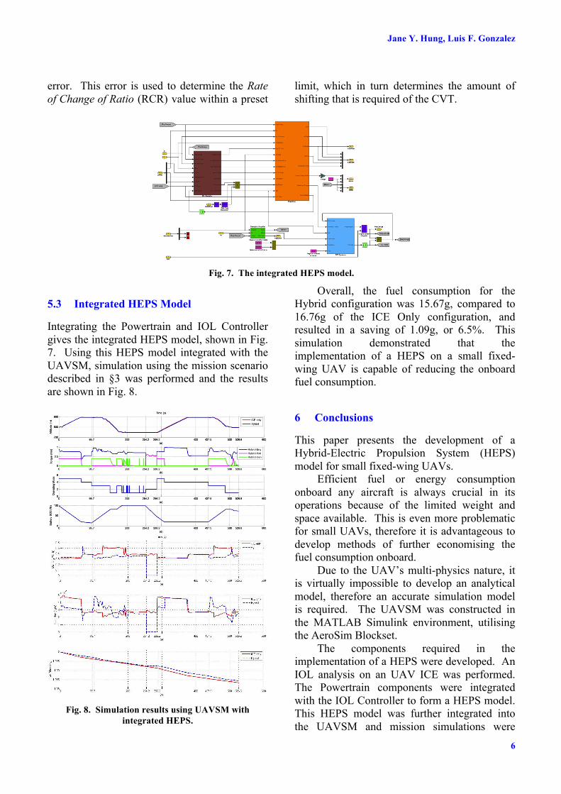
Fig. 7. The integrated HEPS model.
5.3 Integrated HEPS Model
Integrating the Powertrain and IOL Controller gives the integrated HEPS model, shown in Fig. 7. Using this HEPS model integrated with the UAVSM, simulation using the mission scenario described in §3 was performed and the results are shown in Fig. 8.
Fig. 8. Simulation results using UAVSM with
integrated HEPS.
Overall, the fuel consumption for the Hybrid configuration was 15.67g, compared to 16.76g of the ICE Only configuration, and resulted in a saving of 1.09g, or 6.5%. This simulation demonstrated that the implementation of a HEPS on a small fixed-wing UAV is capable of reducing the onboard fuel consumption.
6 Conclusions
This paper presents the development of a Hybrid-Electric Propulsion System (HEPS) model for small fixed-wing UAVs.
Efficient fuel or energy consumption onboard any aircraft is always crucial in its operations because of the limited weight and space available. This is even more problematic for small UAVs, therefore it is advantageous to develop methods of further economising the fuel consumption onboard.
Due to the UAV’s multi-physics nature, it is virtually impossible to develop an analytical model, therefore an accurate simulation model is required. The UAVSM was constructed in the MATLAB Simulink environment, utilising the AeroSim Blockset.
The components required in the implementation of a HEPS were developed. An IOL analysis on an UAV ICE was performed. The Powertrain components were integrated with the IOL Controller to form a HEPS model. This HEPS model was further integrated into the UAVSM and mission simulations were

7
DESIGN, SIMULATION AND ANALYSIS OF A PARALLEL HYBRID ELECTRIC PROPULSION SYSTEM FOR UNMANNED AERIAL VEHICLES
performed. It was demonstrated through these simulations that an UAV with the current HEPS configuration was capable of achieving a fuel saving of 6.5%, compared to the ICE-only configuration.
Some aspects of the research conducted in this paper will require further work. These include the following:
• Inclusion of wind and weather effects in the UAVSM;
• Extension of the flight mission to include take-off and landing sequences; and
• Improvements in the implementation of the IOL Controller, which may result in better fuel savings.
7 References
[1] Unmanned aerial vehicles (UAV). [Online]. Available: http://www.fas.org/irp/program/collect/uav.htm.
[2] Jane’s unmanned aerial vehicles and targets. [Online]. Available: http://juav.janes.com/public/juav/index.shtml
[3] Logan MJ, Chu J, Motter MA, Carter DL, Ol M and Zeune C. Small UAV research and evolution in long endurance electric powered vehicles. AIAA Infotech Aerospace 2007 Conference and Exhibit, Rohnert Park, CA, USA, 7-10 May, 2007.
[4] Glossock R, Hung JY, Walker RA and Gonzalez L. Design, modeling and measurement of hybrid powerplant for unmanned aerial systems (UAS). 5th Australasian Conference on Applied Mechanics, Brisbane, Australia, 10-12 December, 2007.
[5] Bhatia A, Mendiratta A and Vaish M. Comparison of proposed six stroke internal combustion engine with four stroke engine using ideal cycle. Proc. 2nd International Conference on Mechanical and Electronics Engineering (ICMEE2010), Vol. 1, pp. 222-225.
[6] Energy-efficient electric machines. [Online]. Available: http://www.csiro.au/science/ElectricMachines.html
[7] Francisco AB. Implementation of an ideal operating line control strategy for hybrid electric vehicles. M.Sc. Thesis, University of California, Davis, CA, USA, 2002.
[8] Chau KT and Wong YS. Overview of power management in hybrid electric vehicles. Energy Conversion and Management, Vol. 43, No. 15, pp. 1953-1968, 2002.
[9] AeroSim Blockset, aeronautical simulation blockset, ver. 1.2, 2005.
[10] Hung JY. Investigation of methods for increasing the energy efficiency on unmanned aerial vehicles (UAVs). Masters Thesis, Queensland University of Technology, Brisbane, Australia, 2011.
[11] Oudijk MF. Optimization of CVT control: For hybrid and conventional drive lines. Masters Thesis, Eindhoven University of Technology, The Netherlands; University of California, Davis, CA, USA, 2005.
[12] Frank AA. Engine optimization concept for CVT-hybrid systems to obtain the best performance and fuel efficiency. 2004 International Continuously Variable and Hybrid Transmission Congress, Davis, CA, USA, 23-25 September, 2004.
[13] Battery, ser. MATLAB 7.5 documentation. The MathWorks, Inc.
[14] Modeling and simulation of hybrid electric vehicle (HEV). [Online]. Available: http://www.mathworks.com/mason/tag/proxy.html?dataid=12113&fileid=57988&product=PS&ei=cUOeTPTXK4WsvgOvs5CtDQ&usg=AFQjCNFvo87b0FSb703CwlcZ-M5TxLb11Q
[15] Air Thunder 5000mAh 6-cell lithium-polymer (Li-Po) battery pack. [Online]. Available: http://www.airthunder.com
[16] Dortland AE. Building a dynamometer test-stand. Masters Internship Report DCT-2007-134, Eindhoven University of Technology, The Netherlands; University of California, Davis, CA, USA, 22 October 2007.
[17] Brockbank C and Burtt D. Developments in full-toroidal traction drive infinitely and continuously variable transmissions. 14th Asia Pacific Automotive Engineering Conference (APAC-14), Los Angeles, CA, USA, 5-8 August, 2007.
[18] Kriegler W, Zrim A and van Spijk G-J. IC-engines and CVTs in passenger cars: A system integration approach. IMechE International Seminar S540: Advanced Vehicle Transmissions and Powertrain Management, London, UK, 25-26 September, 1997.
8 Copyright Statement
The authors confirm that they, and/or their company or organization, hold copyright on all of the original material included in this paper. The authors also confirm that they have obtained permission, from the copyright holder of any third party material included in this paper, to publish it as part of their paper. The authors confirm that they give permission, or have obtained permission from the copyright holder of this paper, for the publication and distribution of this paper as part of the ICAS2012 proceedings or as individual off-prints from the proceedings.