design procedure and behaviour of advanced flag- shape
TRANSCRIPT
Paper Number XXX
Design Procedure and Behaviour of Advanced Flag-Shape (AFS) MDOF Systems
W.Y.Kam, S.Pampanin & A.J.Carr Department of Civil Engineering, University of Canterbury, Christchurch, New Zealand.
A.Palermo Department of Structural Engineering, Politecnico di Milano, Milan, Italy.
2008 NZSEE Conference
ABSTRACT: The concept of Advanced Flag-Shaped (AFS) systems, in which alternative forms of energy dissipations (yielding, friction or viscous/visco-elastic damping) are combined in series and/or in parallel together with re-centering elements (un-bonded post-tensioning tendons or Smart memory alloy(SMA) elements), has been previously introduced by the authors. Based on numerical analyses on SDOF-systems, the unique combination of friction or hysteretic dampers in series with viscous dampers, further combined in parallel with re-centering and hysteretic dissipation elements, has been shown to be very effective in controlling both force and displacement responses for either far-field and near-fault ground motions. Experimental validation of the effectiveness of the systems based on shake-table testing on wall systems is presented in a companion paper.
In this contribution, the concept of AFS systems is extended to MDOF systems. Preliminary suggestions for a simplified design procedure for AFS connection systems are given within the framework of a Direct Displacement-Based Design (DDBD) approach. Using case-study prototypes of five-storey moment-resisting frame, incorporating four different connection systems, a comparative MDOF study is carried out by the means of non-linear time-history analyses using suites of far-field and near-fault earthquake excitations. The non-linear time history analysis results for both far-field and near-fault earthquakes provided satisfactory validation of the design procedure, though being, as expected, on the conservative side when dealing with velocity-dependent dissipating systems.
As per the results of SDOF systems, AFS systems appear to be capable of providing beneficial attribute to the response of a MDOF system, particularly when dealing with velocity-pulse earthquake record, typical of a near-field event. In addition to providing reduction of peak displacement/drift response and a negligible residual deformation, floor accelerations and column shears due to the higher mode effects are also lessened. In the global performance matrix, AFS systems would achieve a much higher performance level in comparison to the conventional systems. There is however, less than expected contribution from the excitation velocity on dampers’ energy dissipation up the building heights. Based on these results, an approximation for the velocity-dependent devices’ velocities at a given storey is proposed. In conclusion, a brief discussion on limits and potentials for the practical implementation of AFS systems is given, along with anticipation of ongoing and further investigations.
1 INTRODUCTION
In the search of alternative retrofit techniques and new seismic-resisting systems that would perform to the performance objectives in line with the framework of the Performance-based Earthquake Engineering (PBEE), structural systems with the emphasis on minimising damage and financial losses

2
have been recently developed. The introduction of jointed-ductile precast concrete systems (typically referred to as PRESSS-technology), where un-bonded post-tensioned tendons are used in conjunction with hysteretic energy dissipation elements to achieve self-centering capacity, hence guaranteeing negligible residual deformation on the structural systems and assuring minimum damage in the structural elements(Priestley et al., 1999), is considered one of the main seismic research outcome highlights of the past decade. Further research in the development of re-centering systems based on a controlled rocking motion has extended its application to steel (Christopoulos et al., 2002) and timber structures (Palermo et al., 2005). In parallel, investigations have been carried out on the feasibility of combining re-centering systems with viscous damping (Kurama, 2001) or friction energy dissipation devices (Morgen and Kurama, 2004). In conjunction to the development of these new structural system, the argument to use a residual deformation damage index (RDDI), in combination to traditional damage indexes based on ductility, maximum displacement and/or cumulated energy, as a more appropriate damage indicator was made (Pampanin et al., 2002). Recognising that minimal residual deformation as a critical component of a design objectives, as with maximum displacements, better performance levels can be achieved with re-centering structural systems.
The Advanced Flag-Shaped (AFS) system is a sub-set of or further evolution within the re-centering structural systems family. Instead of relying on single-type of energy dissipation, the AFS systems advocate combination alternative forms of energy dissipation in parallel and in series with re-centering elements (such as un-bonded post-tensioned tendons) (Kam et al., 2006; Kam et al., 2007). Figure 1 shows some schematic illustrations of the AFS systems and the practical application of the AFS systems for bridge-pier, structural wall and beam-column joints.
Figure 1: a) AFS Bridge Pier b) Schematic spring-mass SDOF model c) Experimental AFS Structural Wall (Marriott et al., 2007) d) AFS Beam-column Joint
It is worth noting that the combination of various traditional supplementary energy dissipation devices in parallel and/or in series have been proposed and studied in recent years, in particularly for base isolation systems. (Makris and Chang, 2000) have, for example, previously noted on the viability and effectiveness of combining viscous and rubber-bearing (friction) dampers for base isolation systems in near-fault regions. Meanwhile, (Xilin and Qiang, 2002) have investigated numerically and experimentally the combination of viscous oil damper and rubber base dampers in parallel for base isolation systems. Kasai and Minato (Kasai and Minato, 2005) extended the idea of combining viscous and hysteretic dissipation to braced frames in a series of experimental and numerical study.
However, state-of-the-art literature on seismic design of structures including energy dissipation devices and/or supplemental damping systems (Christopoulos and Filiatrault, 2006) has yet to extend its coverage to combination of various energy dissipation “systems”. In addition, while supplementary dampers in the form of viscous or friction dampers have been in practice for decades, the efficiency of velocity-dependent dampers under near-fault event is less well known. Acknowledging the limitation of hysteretic damping from yielding dissipation under low number of cycles and high velocity excitation peculiarities of near-fault earthquakes, the AFS systems take advantage of the velocity-dependent dissipation devices such as visco-elastic dampers in providing sufficient energy dissipation in these events. In the aforementioned previous studies on SDOF study (Kam et al., 2007), re-
(a) (b) (c) (d)

3
centering systems with velocity-dependent energy dissipation have lower ductility demand in comparison to the traditional flag-shape re-centering and monolithic ductile systems, particularly when subjected to earthquake records with forward directivity characteristics.
Building on the results from the SDOF study, two variants of AFS are further investigated here – (a) Non-Linear Elastic Spring with Viscous Dampers, herein named NLEV and (b) Non-linear Elastic Spring in parallel with a combination of hysteretic dissipation and velocity-dependent dampers in series with friction slip devices, herein named AFS. Figure 2 illustrates a simple spring-mass model and the generic hysteresis behaviour of the AFS system (with and without friction slip) under varying excitation velocities. It is expected that, with the use of friction slip on velocity-dependent dampers, the moment/forces within the superstructure can be controlled to a defined limit.
In this paper, the concept of AFS is extended to multi-degree-of-freedoms (MDOF) structures, in particular moment-resisting frames. Critical aspects of the extension of the system to MDOF are briefly discussed, in particular within the context of the Direct Displacement-Based Design (DDBD). Then, critical aspects of a preliminary simplified design procedure for the AFS connection are discussed. Using a case study of a five-storey reinforced concrete frame, the paper attempts to address the effectiveness of the AFS systems and the validity of the design procedure. Lastly, non-linear time history analysis results of the prototype building is presented and analysed. This paper represents a part of the analytical work that belongs to a larger experimental-analytical investigation for advanced seismic resisting system at the University of Canterbury.
Figure 2: (Left) AFS Spring-Mass Model (Right) AFS Generic Hysteresis Behaviour at Varying Frequency - with and without friction slip for viscous dissipation device (Kam et al., 2006).
2 EXTENSION OF ADVANCED-FLAG-SHAPE CONCEPT TO MDOF SYSTEMS
2.1 Critical Aspects
Extending the concept of AFS system developed for SDOF structures to realistic MDOF systems involves several additional and important considerations. The effectiveness of velocity-dependent dampers, placed at the rocking interface of the beam-column joints is unknown, as previous analytical and experimental work is based on bridge piers or shear-wall configurations. Firstly, the induced velocities is expected to vary along the storey height as the beam-column interface gap opening varies up the structure due to the geometry and response of the structure. Secondly, limited information is available in literature on the effects of near-fault events on RC frame MDOF systems (Alavi and Krawinkler, 2001; Hall et al., 1995). Furthermore, the amplification factors due to higher modes and p-delta effects are also critical to the design of these structures. However, due to space limitation, only the first two aspects, namely variation of induced velocities and near-fault effects on AFS MDOF systems, are discussed in this contribution. Study on the amplification factors for traditional or advanced Flag-shape systems are currently under investigations and will be presented in later publication.
2.2 Direct Displacement-Based Design (DDBD) Procedure and Parameters for AFS Frames
The proposed procedure is an addendum to the state-of-the-art practice of the Direct Displacement-based Design (DDBD) method (Priestley et al., 2007). It is now generally accepted that displacement-based design approach yields to more rational design outcomes, where deformations (and therefore

4
damage), under a design-level earthquake can be targeted with reasonable accuracy, in line with the objectives of the performance-based earthquake engineering. A summary illustration of the DDBD procedure is shown on Figure 3 below, and further information is available on literature (Priestley et al., 2007). In a DDBD procedure, the influence of different structural systems on the design outcome is reflected on three key parameters: (1) displacement shape profile, δi (2) yield drift limit governed by the rotation of the plastic members, θy and (3) the equivalent viscous damping ξeq, ξ. of the equivalent (substitute structure) SDOF system.
Firstly, considering that the AFS frame would be designed for a strong-column weak-beam mechanism according to capacity design philosophy, it is postulated that the displacement shape profile, δi for AFS systems are similar to those of regular and conventional frames, with first mode shape dominating the displacement shape profile. The displacement shape profile for regular frames (Priestley et al., 2007) is given by :
Regular Frame: for n ≤ 4: δi = Hi / Hn (Eqn 2.1)
for n > 4: ⎟⎟⎠
⎞⎜⎜⎝
⎛−⎟⎟
⎠
⎞⎜⎜⎝
⎛=
n
i
n
ii H
HHH
41
34δ (Eqn 2.2)
where Hi and Hn are the heights at the level i and n (roof). Preliminary numerical result, as to be presented in Section 4, comparing the design profile and the actual displacement profile from extensive non-linear time history analyses has indicated that Equation 2.1 and 2.2 might not be accurate for system with significant vertical irregularity (column stiffness and beam capacity change up the height).
Secondly, in determining the yield drift, θy for the AFS frame systems, given the increased stiffness from the pre-stressed connections, the beam flexural and shear deformation, as well as the joint shear deformations are in general decreased, while column deformations are unaffected. the yielding drift of the overall frame, θy is thus estimated to be similar to those of the hybrid RC frames with un-bonded post-tensioned tendons, which has been suggested to be about 40-50% of the conventionally reinforced concrete frames (Priestley, 2002).
Thus for either un-bonded post-tensioned RC Frame and AFS RC Frame
θy = 0.25 εy Lbeam / hbeam (Eqn 2.3)
where Lbeam and hbeam are the span length and the depth of the beam.
Lastly, the equivalent viscous damping, ξeq of the equivalent (substitute structure) SDOF systems, for a AFS system can be estimated using the geometric stiffness method or the hysteresis area method (Chopra, 2000; Jacobsen, 1960), where the energy dissipated in a cycle of harmonic AFS hysteresis is equated with a linear visco-elastic system at resonance. The linear system is then assigned an effective stiffness, which was the secant stiffness to the maximum displacement point, and given the maximum displacement under inelastic behaviour, the equivalent viscous damping, ξeq can be estimated. Using that method, equation 2.4 below is derived to estimate the equivalent viscous damping for AFS systems. Due to space limitation, full derivation of Equation 2.4 is not provided here, but will be published in a more detailed research report.
)])(1([
])1()1(21[25.0}{5.02
2
,ssyptptysypty
ssyeffvvV
DESIGNMAX
HYSTERESISAFSeq rFrFFF
rFTSCFA
−−−−
−
+−++
−+−++=
Δ=
μπμμμπμβ
πξ (Eqn 2.4)
Where Cv is the critical damping coefficient, μ is the structural ductility, βv is an effective damping reduction factor for viscous dampers, Sv is the spectra velocity from the design spectra, function of the Teff, effective period. Fy-s, Fy-pt and rs ,rpt are the yield forces and the post-yield stiffness for hysteretic dissipation device and post-tensioned re-centering element respectively.
In an ongoing effort, extensive time-history analysis for AFS systems with varying parameters has been carried out to derive the damping-ductility relationship (ξeq versus μ). As suggested by Figure 3 and Equation 2.4, the equivalent viscous damping from the AFS systems would be also dependent on the excitation velocity. In the illustration in Figure 3, the excitation velocity is denominated by Sv1, Sv2

5
and Sv3, where Svi is a function of the design hazard pseudo-spectra velocity at the effective period of interest.
Figure 3: Fundamentals of DDBD with proposed AFS modification(adopted from Priestley, 2007)
2.3 AFS Connection Simplified Design – Critical Aspects
Upon the derivation of the internal member forces as per the DDBD procedure outlined above, the AFS connections can then be designed for a targeted internal moment capacity M*design while tailoring the seismic behaviour by selecting an appropriate combination of self-centering and dissipation contribution as well as of hysteretic vs. viscous dissipation mode :
a) Select a ratio of re-centering and dissipating moment contribution, λ1 as defined in Equation 2.5. The λ1 ratio governs the self-centering capacity of the system. Therefore, limiting λ1 ratio (as suggested by (NZS3101, 2006) Appendix B.) where λ1 must be at least 1.25, residual displacements can be minimised to a negligible range. The 1.25 limitation accounts for the strain hardening effect in the hysteretic energy dissipation. It should be noted that for AFS systems with significant velocity-dependent energy dissipation, even a system with very low λ1 ratio can achieve full dynamic re-centering as most viscous/visco-elastic dampers have zero force resistance when the excitation ends.
λ1 = Mpre-stressing / Mdissipation ≥ α0 = 1.25 (Eqn 2.5)
b) Establish the ratio of hysteretic (displacement-proportional) and viscous (velocity proportional) damping contribution, λ2. The λ2 ratio controls the distribution of the velocity-dependent and displacement-dependent dissipation contributions of the connection system. It is proposed that the λ2 ratio is limited by an upper bound of 0.75 to ensure adequate energy dissipation is available at the event of low velocity.
λ2 = Mvelocity-dependent-dissipation /(Mhysteretic-dissipation + Mvelocity-dependent-dissipation ) (Eqn 2.6)
c) Using simply relationships of the λ1 ratio and the λ2 ratio, the percentage of contribution of each components (un-bonded tendons, hysteretic dissipation and/or viscous dissipation) can be calculated:
Mprestressed = λ1 / (1 + λ1) · M*design (Eqn 2.7a)

6
Mdissipation = 1 / (1 + λ1) · M*design (Eqn 2.7b) Mvelocity-dependent dissipation = λ2 / (1 + λ2) · M*dissipation (Eqn 2.7c) Mhysteretic dissipation = 1 / (1 + λ2) · M*dissipation (Eqn 2.7d)
d) Next, the critical beam-to-column connection is analysed using a simplified sectional analysis. If the equivalent design force in the dampers due to the excitation velocity, Fv is known, then the moment capacity of the connection can be established by iterative calculation of the neutral axis. A traditional Kelvin model for viscous/visco-elastic dampers can be used to model Fv, as illustrated by Equation 2.8. Excitation velocity, V assumed is further discussed in Section 2.5 and 4.5.
Fv = CVα (Eqn 2.8b)
where the power factor α can vary between 0.15 and 1 depending on the type of viscous device
e) For AFS systems with friction slip component, the friction force is designed to limit the force contribution from the velocity-dependent dampers. Therefore, the friction component can be designed using the following equation:
Ffriction = φfrictionμfriction ⋅ Fnormal ≤ Fv = CVα (Eqn 2.9) Where φfriction , μfriction , Fnormal are the factor of safety coefficient, coefficient of friction and the normal force applied to the friction slip device (e.g. slotted bolts connection).
f) For the design of the viscous or visco-elastic dampers, it is clearly essential to check whether the required displacements and forces can be provided by the dampers, as most dampers can be limited by the maximum length and stroke of the device as well as the maximum force.
2.4 Velocity-dependent energy dissipation devices design considerations
Various design methods have been previously proposed in literature when dealing with velocity-dependent energy dissipation devices as supplementary passive and/or active damping (Christopoulos and Filiatrault, 2006; Hanson and Soong, 2001). Generally, the effective additional equivalent damping due to the added dampers, derived based on energy-based methods, is used to reduce the seismic input (FEMA-450, 2004). For the design of the velocity-dependent device, the structural velocity assumed for passive viscous dampers is calculated from peak pseudo-velocity value at elastic period and a reduction factor (Pekcan, 1998; Ramirez et al., 2002).
As an alternative approach herein presented, the added damping is taken into account directly within DDBD framework, where by target displacement would dictate the required system equivalent viscous damping, ξsys, calculated using Equation 2.4. For the design of the velocity-dependent dissipation devices, two physical parameters need to be specified: (1) the required damping coefficient of C and (2) the required number of dampers to achieve the targeted moment capacity. In addition, the velocity of the dampers has to be estimated using some approximations and recalling that the dampers’ effective velocity is not equal to the ground velocity, or the relative velocity of the structure, typically provided by a spectrum. In the initial design for the modelling, a damping velocity demand profile linearly decreasing with the height of the building was assumed. Based on the numerical results, refinements of such relationship have been derived, as later presented in Section 4.5.

7
3 MULTI-DEGREE-OF-FREEDOM ANALYSIS
3.1 Prototype Structure and Model
The prototype building adopted is the case-study five-storey building structure for the PRESSS-Technology design example handbook (Pampanin and Marriott, 2007), as shown in Figure 6. The DDBD procedure outlined above is implemented for the moment-resisting frame systems to generate the design base shear and design internal forces. The different hysteretic behaviour connections are designed for the same set of design internal forces. It is noted that different type of connection systems would affect the design base shear and design internal forces resulted from the DDBD procedure. However, for comparison purpose, the DDBD procedure assumed the prototype to be an hybrid frame precast concrete system comprising of post-tensioned un-bonded tendons and mild steel dissipaters (thus exhibiting a traditional Flag-shape hysteresis), as that would result in a slightly lower equivalent viscous damping, when compared to a conventional precast emulative solution, which is a conservative assumption. The design drift has been set as 2% under the design level of earthquake (500 yrs return period) in Wellington region, corresponding to a peak ground acceleration of 0.4g and shallow soil (type C according to NZS1170:5 (2006)). Table 1 summarizes the DDBD and the design internal forces for the prototype. It is important to note that, due to the relatively low design spectra (when compared to EC8 spectra for example), the resulting frames are quite flexible as the effective period required to achieve the targeted displacement is much higher. In retrospect, the design inter-storey drift could be set lower (e.g. 1.5%) in order to have a stiffer prototype structure.
Table 1: Summary of DDBD Design
0.223 m 3.9113.199 m 11.491196 tonnes 939.2 kN2.37 sec
Level 1-2 325.0 kNmLevel 3-5 191.4 kNm Interior L1-2 535 kNm
Exterior Column 1
Interior Column Exterior L1-2 268 kNm
Column Axial Load Base: NG+Q+E 90.0 1620.1 Interior L3-5 449 kNmColumn Axial Load L3: NG+Q+E 348.3 946.1 Exterior L3-5 224 kNm
kNmSDOF base overturning moment 12941.6
SDOF design displacementSDOF effective heightSDOF effective mass
SDOF effective periodBeam Design
Moment
SDOF equivalent viscous damping SDOF design base shear
Column Design Moment
SDOF ductility demand
Figure 4: (a) Prototype MDOF Building Geometry (Pampanin and Marriott, 2007)
(b) Lumped mass and plasticity 2D Model
3.2 Hysteresis Models
Four hysteresis models, defined at the plastic-hinge zone, are used to represent the inelastic mechanisms of the different structural systems. The following hysteresis models are adopted to

8
represent the four different types of structural system, namely (a) Bi-linear Inelastic(BL), to represent monolithic reinforced concrete (or steel) connection (b) Flag-Shape (FS), to represent the un-bonded post-tensioning re-centering connection (c) Non-linear elastic with viscous (NLEV), to represent the combination of un-bonded post-tensioning with velocity-activated energy dissipation (d) Advanced Flag-shape (AFS), to represent the combination of traditional flag-shape systems, in parallel with velocity-activated energy dissipation with friction slip, as described in the Introduction. Figure 5 shows the corresponding rotational spring models as lumped plasticity elements and the hysteresis behaviour under cyclic sinusoidal motion for the four hysteresis models
Figure 5: (a) Rotational Spring Models (b) Hysteresis Models under Sinusoidal Cyclic Motion
Given the different source of dissipation, affecting the shape of the hysteresis, it is complicated to establish a yardstick of comparison between the hysteresis models. For this study, “equal” secant stiffness to the yield point and ultimate point are assumed. However, it is assumed that velocity-dependent contribution is maintained at all displacements, while in reality, the moment contribution of the velocity-dependent elements is out-of-phase with the maximum displacement. Figure 6 shows the four calibrated hysteresis models for level 1 and 2 connections under cyclic sinusoidal motion. Table 2 lists the dynamic properties of the models. As expected, systems with post-tensioned tendons (FS and ASF) have shorter elastic periods, except for NLEV system where the viscous dashpots are inducing some flexibility in the frame model. For sake of brevity, the input values for the different hysteretic models for numerical modelling is not included here.
Table 2: Dynamic properties of the models
Model Fundamental Natural Period (sec)
1st Mode Participating Mass (%)
2nd mode Period (sec)
2nd Mode Participating Mass (%)
BL 2.416 73.000 0.609 89.000FS 2.024 75.000 0.551 90.000
NLEV 2.535 72.000 0.624 89.000AFS 2.136 74.000 0.569 90.000

9
Figure 6: Hysteresis Models under Sinusoidal Cyclic Motion (mean velocity = 3.65 rad/s, Frequency =
0.825Hz)
3.3 Modelling Assumption and Strong Ground Motion Records
The inelastic time history analyses were carried out using the finite-element program RUAUMOKO2D (Carr, 2007). A Newmark constant average acceleration integration scheme was adopted along with a Rayleigh damping model proportional to the tangent stiffness. P-delta effects have ignored at this stage. Lumped mass and lumped plasticity modelling are adopted. According to capacity design principles, inelasticity demand is restricted to the base of the columns and in the beams’ end zones.
Two suites of strong ground motion records were used, representing both far-field and near-fault events. All records are taken from the PEER online strong ground motion database (PEER, 2007). The first suite of earthquakes is an ensemble of seven scaled historical ‘far-field’ (without any directivity effect) strong ground motion records. These records were related to soil types C or D (NEHRP categories), with hypocentre depth ranging between 13 and 25km, and were generated by earthquakes of moment magnitude, Mw, ranging from 6.7 to 7.3. The second suite of earthquakes is an ensemble of seven historical near-fault earthquake records, selected based on its PGV/PGA ratio (at least 0.09 ms-1 / ms-2) and distance from fault (less than 10km). Records on shallow and deep soils are selected, though two records on rock site are included for near-fault suite due to its compatibility with the NZS1170:5 design spectra. It is noted that there are limited number of records with directivity effects that is compatible with the NZS1170:5 hazard spectra. The characteristics of the both far-field and near-fault suites of records are presented in Table 3 and Table 4.
The scaling of the earthquake records were done in accordance to the recommendation of the (NZS1170, 2004). As mentioned, the design site is assumed to be Wellington, with peak ground acceleration of 0.4g, located on soil class C and having a probability of exceedance of 10% in 50 years (R=1.0). The scaled earthquakes response spectra are shown in Figure 7. Scaling according to the recommendation of NZS1170.2004, the near-fault records in order to form a uniform hazard suites for both far-field and near-fault suites has proven to be a challenging exercise, whose actual validity and meaning should be object of discussion and debate in the nearest future. Among other alternative approaches when considering near fault records, as suggested in literature and design codes includes the use of large set of records in incremental level of intensity as with incremental dynamic analysis (IDA) method (Tothong et al., 2007) or adaptation of an improved of hazard spectra where magnitude scaling of the peak spectra responses are included (Somerville, 2003).

10
Table 3: Characteristics of the 7 Scaled Far-Field Ground Motion Records
Name Earthquake Event Year Mw Station Rclosest
(km)Soil Type
(NZS1170:5)Unscaled PGA (g)
Unscaled PGV (cm/s)
Scaling Factor
Scaled PGA (g)
Scaled PGV (cm/s)
Scaled PGV/PGA
ratioEQ1 Superstition Hils 1987 6.7 Brawley 18.2 D 0.1335 17.2 3.00 0.401 51.6 0.131EQ2 Northridge 1994 6.7 Canoga Park – Topanga Clan 15.8 D 0.356 32.1 1.27 0.452 40.7 0.092EQ3 Northridge 1994 6.7 LA – Hollywood Stor FF 25.5 C 0.231 18.3 2.15 0.496 39.3 0.081EQ4 Northridge 1994 6.7 N Hollywood – Coldwater Can 14.6 C 0.271 22.2 1.50 0.406 33.3 0.084EQ5 Loma Prieta 1989 6.9 Capitola 14.5 C 0.4798 36.5 1.19 0.571 43.4 0.078EQ6 Landers 1992 7.3 Desert Hot Springs 23.3 D 0.153 20.9 2.09 0.320 43.7 0.139EQ7 Landers 1992 7.3 Yemo Fire Station 24.9 D 0.2095 29.7 1.82 0.382 54.1 0.145
Table 4: Characteristics of the 7 Scaled Near-Fault Ground Motions (Fault Normal Direction)
Name Earthquake Event Year Mw Station Rclosest
(km)Soil Type
(NZS1170:5)Unscaled PGA (g)
Unscaled PGV (cm/s)
Scaling Factor
Scaled PGA (g)
Scaled PGV (cm/s)
Scaled PGV/PGA
ratio (s)EQ1 Northridge 1994 6.7 Newhall Fire Station 5.92 D 0.59 97.20 0.53 0.312 51.4 0.168EQ2 Northridge 1994 6.7 Sylmar - Olive view Med Ctr 5.30 D 0.84 129.60 0.41 0.347 53.4 0.157EQ3 Northridge 1994 6.7 Jensen Filter Plant 7.01 C 0.424 106.2 0.43 0.180 45.1 0.255EQ4 Imperial Valley 1979 6.5 El Centro Array# 7 0.56 D 0.46 109.30 0.52 0.242 57.2 0.241EQ5 Loma Prieta 1989 6.9 Los Gatos Pres Center 3.88 B 0.563 94.8 0.38 0.211 35.6 0.172EQ6 Tabas, Iran 1978 7.35 Tabas 2 D 0.852 121.4 0.58 0.495 70.5 0.145EQ7 San Fernando 1971 6.6 Pacoima Dam Abutment 1.81 B 1.23 112.50 0.51 0.623 57.2 0.094
The NZS1170:5 (2004) site hazard spectra shape with its near-fault amplification at long periods is generally incompatible with the historical near-fault records (recorded in other regions around the world with a wide range of peculiar characteristics), in particular for soil class B and C. The current NZS1170:5 scaling method (NZS1170, 2004) (would result in lower excitation at higher modes (short period) in time-history records for the near-fault suite in comparison to the far-field suite, as shown in Figure 7
Preliminary results might indicate scaling for the displacement spectra or weighted scaling for higher modes excitation periods might be more suitable. Alternatively, the site hazard spectra (acceleration, velocity or displacement-based) can be further improved to account for the higher risk and hazard resulting from the near-fault amplification and the “fling” (or velocity pulse) effect, and it is noted that improved models for near-fault hazard spectra are currently being developed (Somerville, 2003).
Figure 7: Spectral mean and maximum/minimum envelope for the scaled far-field records and near-fault
records compared to the NZS1170:5 (2002) 5% damped design spectrums

11
4 RESULTS
4.1 Far-Field Earthquakes: Average and Envelope Responses
The statistical values over the ensemble of the far-field earthquakes of the maximum (envelope) inter-storey drifts are shown in Figure 8 for the four different structural systems. The mean of the envelope inter-storey drift demand for all four systems are below the target design drift limit of 2%, except for the FS system at higher storeys. The BL and AFS both performed as per design, achieving maximum average inter-storey drift of 2.21% and 2.22% (standard deviation of 0.40% and 0.35%) respectively. The FS system has significantly higher maximum average inter-storey drift of 2.80% (standard deviation of 0.66%), in particular at the upper levels. Noting that the FS system has higher stiffness at the connection, with shorter building period, it has higher upper modes amplification than the other systems. The NLEV system has the lowest average inter-storey drift response of all the systems, with maximum of 1.47% at level 4 (with standard deviation of 0.24%), which might indicate that the design velocity assumed for the velocity-dependent devices when targeting similar equivalent SDOF response were underestimating the actual device velocities during the seismic. This is acceptable since it leads to conservative design. It is worth noting that the NLEV system also has a much lower dispersion of responses indicating a better control of the peak behaviour from velocity-induced energy dissipation.
In the distribution of the maximum drift along the building elevation, all the systems exhibit lower inter-storey drifts at first storey and higher values at the upper levels. The cantilever-like displacement response might suggest that the base columns are stiffer than required. The increased demand at upper storeys is a clear indication of higher mode effects. In the displacement-based design methodology, the critical drift is assumed to occur at the first floor, as implied by the displacement profile given by Equation 2.1 and Equation 2.2. However, as Table 2 has shown, with first mode participating masses about 74-76% for this flexible prototype frame, the contribution from higher modes is not negligible. Previous work on DDBD-designed RC frames also highlighted similar higher response at upper storeys, in particular for taller frames(Pettinga and Priestley 2005). Further analyses, currently on-going, with a range of building heights and seismic masses (hence a range of structural periods) would give a better indication of suitable displacement profiles for AFS systems.
NLEV
0
1
2
3
4
5
0 1 2 3 4Interstorey Drift (%)
Stor
ey
AFS
0
1
2
3
4
5
0 1 2 3 4Interstorey Drift (%)
Stor
ey
BL
0
1
2
3
4
5
0 1 2 3 4Interstorey Drift (%)
Stor
ey
FS
0
1
2
3
4
5
0 1 2 3 4Interstorey Drift (%)
Stor
ey
Figure 8: Statistical envelope for inter-storey drifts of the 7 far-field earthquakes (from top left, clockwise)
(a) Bi-Linear (b) Flag-Shape (c) Advanced Flag-Shape (d) Non-Linear Elastic with Viscous

12
The average beam shear and the cumulative storey shear for the four systems under far-field records are presented in Figure 9. It can be seen that both the storey shear distribution along the height and also the base shear for the four systems agree well with the DDBD design values. The slightly higher base shear in the MDOF systems, due to high modes amplification is not however explicitly taken into account in a traditional DDBD procedure, though amplification factors for column shear can be accounted for (Pettinga and Priestley 2005; Priestley et al., 2007).
Similarly, the beam shear values up the building height generally agree well with the DDBD design values. However, the beam shear values are lower at the lower stories and higher in the upper stories in comparison to the design values. This can be attributed to the higher modes displacement profiles that the structure undergoes. It can be also appreciated that the NLEV system has the highest base shear amongst the systems, though the variation is less than 10%.
0
1
2
3
4
5
0 50 100Beam Shear (kN)
Stor
ey
BLFSNLEVAFSDDBD
0
1
2
3
4
5
0 500 1000 1500Storey Shear (kN)
Stor
ey
BLFSNLEVAFSDDBD
Figure 9: (Left): Average beam shear envelope for 7 far-field earthquakes (Right): Average cumulative
storey shear envelope for 7 far-field earthquakes
4.2 Near-Fault Earthquakes: Average and Envelope Responses
The statistical values over the ensemble of the near-fault earthquakes of the envelope inter-storey drifts are shown in Figure 10 for the four different structural systems. On average, the mean peak responses of the near-fault earthquakes analyses are similar to those achieve in the far-field earthquakes analysis.
BL
0
1
2
3
4
5
0 1 2 3 4Interstorey Drift (%)
Stor
ey
NLEV
0
1
2
3
4
5
0 1 2 3 4Interstorey Drift (%)
Stor
ey
FS
0
1
2
3
4
5
0 1 2 3 4Interstorey Drift (%)
Stor
ey
AFS
0
1
2
3
4
5
0 2 4Interstorey Drift (%)
Stor
ey
Figure 10: Statistical envelope for inter-storey drifts of the 7 near-fault earthquakes (from top left,
clockwise) (a) Bi-Linear (b) Flag-Shape (c) Advanced Flag-Shape (d) Non-Linear Elastic with Viscous
13
Qualitatively, velocity dependent systems, NLEV and AFS performed better, with average maximum inter-storey drifts below or slightly exceeding the design drift of two percents (1.76% and 2.25% with standard deviation of 0.21% and 0.28% respectively). On the other day, hysteretic-dissipation dependent systems, BL and FS exceeded the design drift more significantly at upper storeys (2.45% and 2.64% with standard deviation of 0.39% and 0.27% respectively). These results highlight the inadequacy on relying purely on displacement-dependent energy dissipation as there could be significantly fewer displacement cycles in a near-fault event.
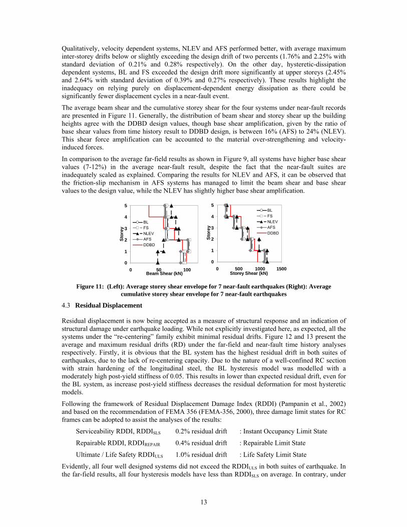
The average beam shear and the cumulative storey shear for the four systems under near-fault records are presented in Figure 11. Generally, the distribution of beam shear and storey shear up the building heights agree with the DDBD design values, though base shear amplification, given by the ratio of base shear values from time history result to DDBD design, is between 16% (AFS) to 24% (NLEV). This shear force amplification can be accounted to the material over-strengthening and velocity-induced forces.
In comparison to the average far-field results as shown in Figure 9, all systems have higher base shear values (7-12%) in the average near-fault result, despite the fact that the near-fault suites are inadequately scaled as explained. Comparing the results for NLEV and AFS, it can be observed that the friction-slip mechanism in AFS systems has managed to limit the beam shear and base shear values to the design value, while the NLEV has slightly higher base shear amplification.
0
1
2
3
4
5
0 50 100Beam Shear (kN)
Stor
ey
BLFSNLEVAFSDDBD
0
1
2
3
4
5
0 500 1000 1500Storey Shear (kN)
Stor
eyBLFSNLEVAFSDDBD
Figure 11: (Left): Average storey shear envelope for 7 near-fault earthquakes (Right): Average
cumulative storey shear envelope for 7 near-fault earthquakes
4.3 Residual Displacement
Residual displacement is now being accepted as a measure of structural response and an indication of structural damage under earthquake loading. While not explicitly investigated here, as expected, all the systems under the “re-centering” family exhibit minimal residual drifts. Figure 12 and 13 present the average and maximum residual drifts (RD) under the far-field and near-fault time history analyses respectively. Firstly, it is obvious that the BL system has the highest residual drift in both suites of earthquakes, due to the lack of re-centering capacity. Due to the nature of a well-confined RC section with strain hardening of the longitudinal steel, the BL hysteresis model was modelled with a moderately high post-yield stiffness of 0.05. This results in lower than expected residual drift, even for the BL system, as increase post-yield stiffness decreases the residual deformation for most hysteretic models.
Following the framework of Residual Displacement Damage Index (RDDI) (Pampanin et al., 2002) and based on the recommendation of FEMA 356 (FEMA-356, 2000), three damage limit states for RC frames can be adopted to assist the analyses of the results:
Serviceability RDDI, RDDISLS 0.2% residual drift : Instant Occupancy Limit State
Repairable RDDI, RDDIREPAIR 0.4% residual drift : Repairable Limit State
Ultimate / Life Safety RDDIULS 1.0% residual drift : Life Safety Limit State
Evidently, all four well designed systems did not exceed the RDDIULS in both suites of earthquake. In the far-field results, all four hysteresis models have less than RDDISLS on average. In contrary, under

14
the near-fault results, it can be observed that the traditional BL system has significantly higher residual drifts. This can be attributed to the low-cycles, large pulse motion nature of the near-fault records, which in turn yield the BL system.
0
1
2
3
4
5
0.0 0.1 0.2 0.3 0.4Average Residual Drift (%)
Stor
ey
BL Average
NLEV Average
AFS Average
FS Average
RDDI-SLS
0
1
2
3
4
5
0.0 0.1 0.2 0.3 0.4 0.5 0.6 0.7 0.8Maximum Residual Drift (%)
Stor
ey
BL Max
NLEV Max
AFS Max
FS Max
RDDI-SLS
RDDI-Repair
Figure 12: Average and maximum residual inter-storey drift under 7 far-field earthquakes
0
1
2
3
4
5
0.0 0.1 0.2 0.3 0.4Average Residual Drift (%)
Stor
ey
BL AverageNLEV AverageAFS AverageFS AverageRDDI-SLS
0
1
2
3
4
5
0.0 0.1 0.2 0.3 0.4 0.5 0.6 0.7 0.8Maximum Residual Drift (%)
Stor
eyBL MaxNLEV MaxAFS MaxFS MaxRDDI-SLSRDDI-Repair
Figure 13: Average and maximum residual inter-storey drift under 7 near-fault earthquakes
4.4 Floor acceleration
The floor acceleration result highlights another advantage of the AFS systems, where floor acceleration response is reduced with velocity-dependent damping systems. Figure 14 presents the average peak floor acceleration for the four hysteresis models for far-field and near-fault suites. NLEV system achieved reduction of floor acceleration from 11% to 39% in comparison to the FS system, which has the highest acceleration response (slightly higher than a BL system). Similarly, AFS system achieved reduction of floor acceleration from 6% to 26% in both far-field and near-fault earthquake suites. Recognising the multiple damage states for acceleration-sensitive non-structural elements, following the commendation of HAZUS (HAZUS-MH-MR3, 2003), three acceleration-based limit states can be indicatively adopted:
A1: Slight damage limit states : 0.25g
A2: Moderate damage limit states : 0.5g
A3: Extensive damage limit states : 1.0g
For far-field results, it can be seen that all systems except for NLEV reached A2. However, it can be observed that the FS systems resulted to slightly higher floor acceleration response in all storeys. For the near-fault results, the hierarchy of performance is similar between the systems, with FS system exhibiting an average top floor acceleration of 0.64g (with maximum value under one single event of 1.0g). As previously discussed, extensive numerical analyses on a set of different buildings with different heights and geometrical properties are required before being able to derive appropriate trends or design guidelines.

15
0
1
2
3
4
5
0 0.2 0.4 0.6 0.8 1Peak Acceleration (g)
Stor
ey
BL
FS
NLEV
AFS
DS1
DS2
x
0
1
2
3
4
5
0 0.2 0.4 0.6 0.8 1Peak Acceleration (g)
Stor
ey
BL
FS
NLEV
AFS
DS1
DS2
x
Figure 14: (a) Average floor acceleration for 7 far-field earthquakes (b) Average floor acceleration for 7
near-fault earthquakes
4.5 Induced velocity on energy dissipation devices at the beam-column joints
As described before, the velocity-dependent energy dissipation devices are assumed to be located at the plastic hinge zone of the beams. A non-linear distribution of velocity is expected to occur along the height of the building, depending on the building geometry and characteristics. Based on preliminary numerical results based on a variation of damping coefficients and of the ground motion excitation characteristics, a series of Equations (4.3a,b,c) are proposed for an approximate evaluation of the dampers velocity assumed to be located at mid-depth of the beam at each level i, up to n level. As expected, the velocity in the dampers is directly proportional to the peak-response-velocity, derived from the design response spectrum, Sv and the location of the dampers vertically.
.)( 1
∑+=
i
ieffvi h
hTSV β i =1 (Eqn 4.3a)
.)(∑
=i
ieffvi h
hTSV β 1< i < n (Eqn 4.3b)
.)( 1
∑−=
i
ieffvi h
hTSV β i =n (Eqn 4.3c)
where β is a velocity reduction factor, tentatively proposed to be 0.10 and 0.15 for reinforced concrete frame under near-fault and far-field earthquakes respectively. The factor reduces the floor plane-velocity to the rotation velocity at the plastic hinge intersection. However with limited data from one case study prototype of MDOF frame, further studies with varying frame geometries are required in order to establish a more reliable relationship between β and geometrical and damping parameters.
Alternatively, to estimate the dampers’ velocity, the dampers’ design displacement, Δ1D and design effective periods, T1D√μD, can be used, as shown by Equations 4.4 (FEMA-450, 2004).
DD
DD T
Vμ
π1
12 Δ= (Eqn 4.4)
The mean values of the “actual” rotational velocity of the velocity-dependent devices for both the far-field and near-fault earthquakes set is presented on Figure 15. Both Equation 4.3 and 4.4 are also implemented for both sets of earthquakes, assuming the design velocity spectra of NZS1170:5 (2004). It is noted that near-fault earthquakes have a lower average values, but this is again attributed to the scaling issue of the near-fault earthquakes as discussed at Section 4.2.

16
0
1
2
3
4
5
-0.12 -0.06 0 0.06 0.12Average Rotational Velocity (rad/s)
Stor
ey
Average NLEV Equation 4.3 FEMA 450 Average AFS
0
1
2
3
4
5
-0.12 -0.06 0 0.06 0.12
Average Rotational Velocity (rad/s)
Stor
ey
Average NLEV Equation 4.3 FEMA 450 Average AFS Figure 15: Rotational Velocity along the building height – actual and prediction values: (left): Far-field
earthquakes (right) Near-fault earthquakes (yet to update for 7EQ set)
5 CONCLUSIONS
This paper presents the extension of the concept of Advanced Flag-Shape Systems, in which alternative forms of energy dissipations (yielding, friction or viscous/visco-elastic damping) are combined in series and/or in parallel together with re-centering element, to MDOF systems, in particular moment-resisting frames. A simple design procedure based on a displacement-based design approach with additional consideration on velocity demand is provided for the design of Advanced Flag Shape MDOF structural systems. A relationship for equivalent viscous damping of the substitute SDOF structure to the structural parameters and ductility for AFS systems is provided.
It is worth noting that given the relatively limited amount of numerical investigation and case-study buildings adopted, several of the design equations provided are intended to provide a general framework, with further analysis are underway to improve their accuracy. The results of non-linear time history analyses using a suit of far-field and near-fault earthquakes provided satisfactory validation of the design procedure, though being on the conservative side, as expected, when dealing with the velocity-dependent systems. Results have shown the presence of significant higher modes effect, as given by the higher inter-storey drift demands at upper storey compared to the conventional first-mode deformation.
The advanced flag-shape systems – NLEV and AFS – both exhibits superior performance in controlling the inter-storey drifts in both far-field and near-fault excitations, in comparison to the BL and FS systems. This enhanced performance is achieved without any significant increase in base shear (or column moments), particularly for the AFS system where friction-slip mechanism controlled the peak force from the viscous dampers. All the re-centering systems achieved negligible residual deformations, indicating minimal damage to the structural components. The advanced flag-shape systems (NLEV and AFS) also achieved better performance in controlling the floor acceleration response, which indicate a lower damage to the acceleration-sensitive non-structural components.
Overall, it has been shown here that the advanced flag shape systems have much more superior performance in achieving a targeted performance level. In the global performance matrix, a function of maximum inter-storey drift, residual deformation and peak floor acceleration, AFS systems would achieve a much higher performance level in comparison to the conventional systems.
6 ACKNOWLEDGEMENT
The financial support provided by the NZ FRST under the research project ‘Retrofit Solutions for NZ” (FRST Contract No. UOAX0411) is greatly appreciated. The earthquake records are downloaded from the PEER Ground Motion Database website.

17
REFERENCES:
Alavi, B., and Krawinkler, H. (2001). "Effects of Near-Fault Ground Motions on Frame Structures." The John A. Blume Earthquake Engineering Center, Stanford University, Stanford, California.
Carr, A. (2007). "RUAUMOKO2D - The Maori God of Volcanoes and Earthquakes." University of Canterbury, Christchurch, New Zealand, Inelastic Analysis Finite Element program.
Chopra, A. K. (2000). Dynamics of Structures - Theory and Applications to Earthquake Engineering, Prentice Hall, New Jersey.
Christopoulos, C., and Filiatrault, A. (2006). Principles of Passive Supplemental Damping and Seismic Isolation, IUSS Press, Pavia, Italy.
Christopoulos, C., Filiatrault, A., and Folz, B. (2002). "Seismic response of self-centering hysteresis SDOF systems." EESD, 31, 1131-1150.
FEMA-356. (2000). "Pre-Standard and Commentary for the Seismic Rehabilitation of Buildings." Federal Emergency Management Agency., Washington, D.C.
FEMA-450. (2004). "NEHRP Recommended Provisions and Commentary for Seismic Regulations for New Buildings and Other Structures. 2003 Edition." Federal Emergency Management Agency, Washington, D.C.
Hall, J. F., Heaton, T. H., Halling, M. W., and Wald, D. J. (1995). "Near-Source Ground Motion and its Effects on Flexible Buildings." Earthquake Spectra, 11(4), 569-605.
Hanson, R., and Soong, T. T. (2001). Seismic Design with Supplementary Energy Dissipation Devices, EERI Publication, Oakland, USA.
HAZUS-MH-MR3. (2003). "Technical Manual for HAZUS-MH-MR3." FEMA, Washington, D.C.
Jacobsen, L. S. "Damping in composite structures." 2nd World Conference on Earthquake Engineering Kyoto, Japan, pp 1029-1044.
Kam, W. Y., Pampanin, S., Palermo, A., and Carr, A. "Advanced Flag-Shaped Systems for High Seismic Performance." First European Conference on Earthquake Engineering and Seismology (ECEES), Geneva, Switzerland.
Kam, W. Y., Pampanin, S., Palermo, A., and Carr, A. "Advanced Flag-Shape Systems for Design and Retrofit for Near-Fault Structures (Conference Best Research Paper 2007)." NZSEE 2007 Conference, Palmerston North.
Kasai, K., and Minato, N. "Experiment and Analysis of a Steel Frame with Visco-Elasto-Plastic Damper." International Symposum on Earthquake Engineering (ISEE Kobe 2005), Kobe.
Kurama, Y. C. (2001). "Seismic Design of Unbonded Post-Tensioned Precast Concrete Walls with Supplementary Viscous Damping." ACI Structural Journal, 97(4), 648-658.
Makris, N., and Chang, S.-P. (2000). "Effect of viscous, viscoplastic and friction damping on the response of seismic isolated structures." EESD, 29, 85-107.
Marriott, D., Pampanin, S., Bull, D. K., and Palermo, A. "Improving the seismic performance of existing reinforced concrete buildings using advanced rocking wall solutions." NZSEE 2007, Palmerston North, NZ.
Morgen, B. G., and Kurama, Y. C. (2004). "A Friction Damper for Post-Tensioned Precast Concrete Moment Frames." PCI Journal, 49(4), 112-133.
NZS1170. (2004). "NZS 1170.5:2004 Structural Design Actions." Standards New Zealand, Wellington, New Zealand.
NZS3101. (2006). "NZS 3101:2006 Concrete Structures Standards." Standards NZ, Wellington, NZ.
Palermo, A., Pampanin, S., Buchanan, A., and Newcombe, M. "Seismic Design of Multi-Storey Buildings using Laminated Veneer Lumber (LVL)." NZSEE Conference, Wairakei, New Zealand.

18
Pampanin, S., Christopoulos, C., and Priestley , N. M. J. (2002). Residual Deformations in the Performance-Based Seismic Assessment of Frame Structures, IUSS PRESS, ROSE School, Pavia, Italy,.
Pampanin, S., and Marriott, D. (2007). "PRESSS Technology: Reinforced Concrete Building Design Example." University of Canterbury, Christchurch, NZ.
PEER. (2007). "PEER Strong Motion Database." University of California Berkeley, Berkeley, California.
Pekcan, G. (1998). "Design of Seismic Energy Dissipation Systems for Reinforced Concrete and Steel Structures (Phd Thesis)," Phd, State University of New York (SUNY), New York City.
Pettinga, D., and Priestley , N. M. J. (2005). "Dynamic Behaviour of Reinforced Concrete Frames Designed with Direct Displacement-Based Design." 2005/02, IUSS Press, Pavia.
Priestley , N. M. J., Calvi, G. M., and Kowalsky, M. J. (2007). Displacement-Based Seismic Design of Structures, IUSS Press, Pavia, Italy.
Priestley , N. M. J., Sritharan, S., Conley, J. R., and Pampanin, S. (1999). "Preliminary Results and Conclusions from the PRESSS Five-Story Precast Concrete Test Building." PCI Journal, 44(6), 42-67.
Ramirez, O. M., Constantinou, M. C., Gomez, J. D., Whittaker, A. S., and Chrysostomou, C. Z. (2002). "Evaluation of Simplified Methods of Analysis of Yielding Structures with Damping Systems." earthquake Spectra, 18(3), 501-530.
Somerville, P. (2003). "Magnitude scaling of the near-fault rupture directivity pulse." Physics of the Earth and Planetary Interiors, 137, 201-212.
Tothong, P., Cornell, A., and Baker, J. W. (2007). "Explicit Directivity-Pulse Inclusion in Probabilistic Seismic Hazard Analysis." Earthquake Spectra, 23(4), 867-891.
Xilin, L., and Qiang, Z. (2002). "Dynamic analysis method of a combined energy dissipation system and its experimental verification." EESD, 31(6), 1251-1265.