design parameters influence on the static workspace and
TRANSCRIPT

HAL Id: lirmm-03141529https://hal-lirmm.ccsd.cnrs.fr/lirmm-03141529
Submitted on 15 Feb 2021
HAL is a multi-disciplinary open accessarchive for the deposit and dissemination of sci-entific research documents, whether they are pub-lished or not. The documents may come fromteaching and research institutions in France orabroad, or from public or private research centers.
L’archive ouverte pluridisciplinaire HAL, estdestinée au dépôt et à la diffusion de documentsscientifiques de niveau recherche, publiés ou non,émanant des établissements d’enseignement et derecherche français ou étrangers, des laboratoirespublics ou privés.
Design Parameters Influence on the Static Workspaceand the Stiffness Range of a Tensegrity Mechanism
Giorgio Mackenzie Cruz-Martinez, Juan Carlos Avila-Vilchis, Adriana VilchisGonzález, Salih Abdelaziz, Philippe Poignet
To cite this version:Giorgio Mackenzie Cruz-Martinez, Juan Carlos Avila-Vilchis, Adriana Vilchis González, Salih Abde-laziz, Philippe Poignet. Design Parameters Influence on the Static Workspace and the Stiffness Rangeof a Tensegrity Mechanism. International Symposium on Advances in Robot Kinematics (ARK 2020),Dec 2020, Ljubljana, Slovenia. pp.15-24, �10.1007/978-3-030-50975-0_3�. �lirmm-03141529�

Design parameters influence on the staticworkspace and the stiffness range of a tensegritymechanism
G. M. Cruz-Martinez1, J-C Avila Vilchis2, A. Vilchis Gonzalez2, S. Abdelaziz1
and P. Poignet1
Abstract This paper deals with the impact of the design parameters on the staticworkspace and the stiffness range of a planar 3-DoF tensegrity mechanism. Thestatic model is established through the energetic approach and the stiffness is de-rived analytically along the 3-DoF of the mechanism. The design parameters con-sidered here are the spring stiffness and the location of the mechanism attachmentpoints to the base. Results on the impact of these parameters are finally analyzed.This analysis constitutes a first step towards the geometric optimization of tensegritymechanisms.
Key words: Tensegrity mechanism, static workspace, stiffness range.
1 Introduction
The term tensegrity was created by Richard B. Fuller as a union of ‘tensional’ and‘integrity’ [6]. A tensegrity structure is formed entirely by a combination of rigidand flexible elements. Its configuration stands by itself and maintains its form solelybecause its structural members (struts) are suspended in a network of tensional ele-ments (cables or springs) [13]. Tensegrity structures are characterized by being light,deployable and of variable stiffness [1]. Working with these structures has been ofinterest for engineers and researchers since tensegrity applications range from mo-bile robotics [5], manipulators [7, 14] and robots in medical applications [3].
Developing mathematical models (a kinematic one, for instance) for tensegritymechanisms is challenging [11, 12, 18] and requires to know the extension of flex-ible elements at all time so as to establish a relationship between the joint and the
The Authors (1) are with the LIRMM, Universite de Montpellier, CNRS, France.e-mail: [giorgio-mackenzie.cruz-martinez, abdelaziz, poignet]@lirmm.frThe Authors (2) are with Autonomous University of Mexico State, Mexico.e-mail: [avilchisg, jcavilav]@uaemex.mx
1

2 Authors Suppressed Due to Excessive Length
cartesian variables. If the measurement of these extensions is not available, staticmodeling is considered. Several methods have been proposed in the literature todetermine the equilibrium configurations of tensegrity mechanisms [8, 15]. Staticworkspace computation, using a continuous approach, has been proposed by [2] fora 2-DoF tensegrity mechanism.
For the tensegrity mechanism reported in this paper, a potential energy approachis considered in order to determine stable equilibrium configurations based on thestiffness analysis. This paper is an attempt to understand the influence of one geo-metric parameter on static workspace and the stiffness range. The geometric param-eter under observation concerns the mechanism attachment points. This analysisconstitutes the first step towards the geometric optimization of tensegrity mecha-nisms.
This paper is organized as follow. The 3-DoF planar tensegrity mechanism isdescribed in section 2. The respective static and stiffness models are presented insubsection 2.1. These models are synthesized using an energetic approach. The com-putation of the static workspace and stiffness range are presented in subsection 2.2.The impact of the design parameters on the static workspace and the stiffness rangeis finally discussed in section 3.
2 Mechanism Description
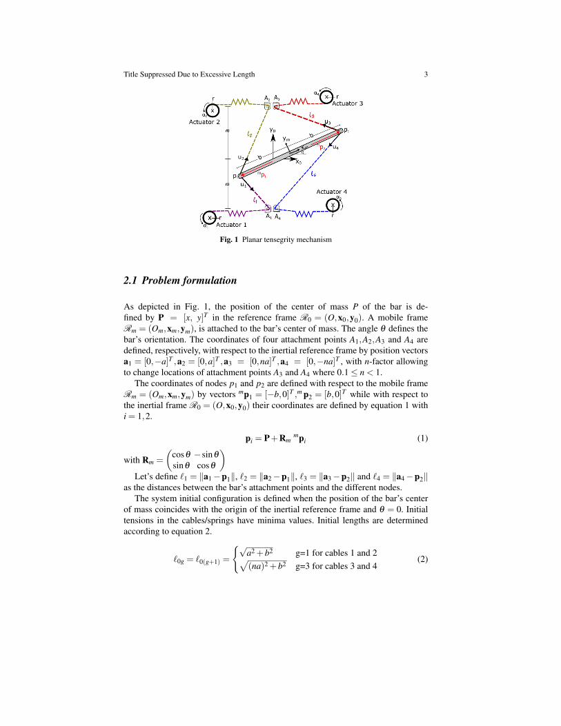
Fig 1 shows a 1-bar planar tensegrity mechanism driven by 4 actuators. Accordingto the classification proposed by Skelton [17], this mechanism is a class-1 tenseg-rity system. The actuators are connected to the bar, of length 2b, using cables andsprings. The springs are considered here identical of stiffnesses k. The cables, at-tached to the bar on p1, are enrolled on pulleys fixed on A1 and A2 and are connectedto springs before being enrolled on pulleys mounted on the actuators 1 and 2. Theother two cables, attached to p2, are enrolled on pulleys fixed on A3 and A4 and areenrolled on pulleys mounted on the actuators 3 and 4.
Title Suppressed Due to Excessive Length 3
Fig. 1 Planar tensegrity mechanism
2.1 Problem formulation
As depicted in Fig. 1, the position of the center of mass P of the bar is de-fined by P = [x, y]T in the reference frame R0 = (O,x0,y0). A mobile frameRm = (Om,xm,ym), is attached to the bar’s center of mass. The angle θ defines thebar’s orientation. The coordinates of four attachment points A1,A2,A3 and A4 aredefined, respectively, with respect to the inertial reference frame by position vectorsa1 = [0,−a]T ,a2 = [0,a]T ,a3 = [0,na]T ,a4 = [0,−na]T , with n-factor allowingto change locations of attachment points A3 and A4 where 0.1≤ n < 1.
The coordinates of nodes p1 and p2 are defined with respect to the mobile frameRm = (Om,xm,ym) by vectors mp1 = [−b,0]T ,m p2 = [b,0]T while with respect tothe inertial frame R0 = (O,x0,y0) their coordinates are defined by equation 1 withi = 1,2.
pi = P+Rmmpi (1)
with Rm =
(cosθ −sinθ
sinθ cosθ
)Let’s define `1 = ‖a1−p1‖, `2 = ‖a2−p1‖, `3 = ‖a3−p2‖ and `4 = ‖a4−p2‖
as the distances between the bar’s attachment points and the different nodes.The system initial configuration is defined when the position of the bar’s center
of mass coincides with the origin of the inertial reference frame and θ = 0. Initialtensions in the cables/springs have minima values. Initial lengths are determinedaccording to equation 2.
`0g = `0(g+1) =
{√a2 +b2 g=1 for cables 1 and 2√(na)2 +b2 g=3 for cables 3 and 4
(2)

4 Authors Suppressed Due to Excessive Length
Due to the presence of springs and in order to determine the static configurationof the mechanism, an energetic approach is considered. It means that the first andsecond derivatives of the potential energy of the system U are used to establish thestable static equilibrium points. Equation 3 defines the total potential energy.
U =4
∑h=1
12
ke2h (3)
where eh is the elongation of the spring h that can be computed as in equation 4.
eh = ρh + `h− `0h for h=1,2,3,4 (4)
with ρh being the displacement of the cable h. It is computed as ρh = rαh, wherer is the radius of the actuator’s pulley and αh is the angular position of the actuator h.
The static equilibrium of the bar is obtained by, simultaneously, solving the equa-tions 5.
∂U∂x
= 0,∂U∂y
= 0,∂U∂θ
= 0 (5)
A stable equilibrium configuration must satisfy inequalities in equation 6.
∂ 2U∂x2 > 0,
∂ 2U∂y2 > 0,
∂ 2U∂θ 2 > 0 (6)
2.2 Characterization of the Static workspace and the Stiffnessrange
The static workspace of a tensegrity system is defined as the set of all stable equi-librium configurations that its end-effector is able to reach [2], while taking intoaccount the unilateral nature of the cables, i.e. The tensions in all the cables mustremain positive.
Each point in the workspace has a minimum and maximum stiffness value. Therange of stiffness for each point is computed by subtracting the maximum and theminimum stiffness values. In order to analyze the static workspace as well as thestiffness range of a tensegrity mechanism, as a function of design parameters, thetensions limits are considered identical in all the study.
The static equilibrium of the mechanism can be expressed in a similar way as forcable-driven parallel manipulators [9, 10] in accordance with equation 7
Wτ = f (7)
where W represents a 3× 4 wrench matrix that depends on the mechanism po-sition P and its orientation θ . The tensions in the cables are identified by vectorτ = [τ1,τ2,τ3,τ4]
T . The vector f represents the wrench applied to the mechanism bymeans of the cables tensions. The wrench matrix W is computed by Equation 8.

Title Suppressed Due to Excessive Length 5
W =
[u1 u2 u3 u4
p1×u1 p1×u2 p2×u3 p2×u4
](8)
where uh represents the unit vector. Its direction is defined as the cable direction (cf.Fig 1).
The tension in the cables must remain in between a minimum and a maximumvalues, respectively τmin and τmax. The stiffness range for a given stable equilibriumconfiguration is computed by varying the tensions in the cables without affectingthe position and orientation of the mechanism. These tensions are computed as:
τ = W+f+Hλ (9)
where WWW+ is the Moore-Penrose generalized inverse of W [16]. H is a vector ofdimension 4×1 whose column span the null space of W. λ is an arbitrary scalar. Tokeep a stable equilibrium configuration, the wrench f is considered equal to a nullvector. The bounds of λ can be obtained by solving the inequality 10.
τmin ≤Hλ ≤ τmax (10)
The bounds λmin and λmax allowing to compute two vector tensions solutions thatenable to keep the equilibrium:
τmin = Hλmin
τmax = Hλmax(11)
Using the vectors τmin and τmax, one can compute the minimum and maximumsprings elongations. Solving the equation 4, can be calculated ρmin and ρmax bothare vectors that contain the set of minimum and maximum displacements for eachactuators. Now the minimum and maximum stiffness are computed using the equa-tion 12 at a given pose of the mechanism (P, θ) considering ρmin and ρmax.
Kminx =
∂ 2U(P,θ ,ρmin)
∂x2 , Kminy =
∂ 2U(P,θ ,ρmin)
∂y2 , Kminθ =
∂ 2U(P,θ ,ρmin)
∂θ 2
Kmaxx =
∂ 2U(P,θ ,ρmax)
∂x2 , Kmaxy =
∂ 2U(P,θ ,ρmax)
∂y2 , Kmaxθ =
∂ 2U(P,θ ,ρmax)
∂θ 2
(12)
3 Discussion of the results
This section show the estimation of the static workspace and stiffness range. Thestatic workspace of the system describes the pose of the end-effector in the x,ycoordinates and the orientation along z axis. The parameters of the mechanism thatare used were: a = 0.1m, b = 0.1m, τh ∈ [4,10]N and ρh ∈
[ 4k ,
10k
]m.

6 Authors Suppressed Due to Excessive Length
The Fig. 2 shows the relationship between the size of the workspace and thespring stiffness values k. The first column shows the static workspace of the mech-anism with n = 1 and k = 270 N/m and the second column shows the staticworkspace when n = 1 and k = 80 N/m. The black dots represent the end-effectorin a stable equilibrium configuration that the mechanism can reach, the red lineshows the mechanism’s boundary of static workspace with k = 270 N/m. In thesecond column the green line shows the boundary of static workspace with k = 80N/m and the red line is superimposed to highlight how the workspace is affected inrelationship with the modification of the stiffness springs, noting that the value of kis inversely proportional to the static workspace.
Fig. 2 Relationship between static workspace and variation of k
In order to analysis the influence of the geometrical parameters on the staticworkspace and stiffness range, here is presented the results when n = 1 (Fig. 1),n= 0.5 (Fig.3a) and n= 0.1 (Fig. 3b). These variation of n causes that the symmetryin the y-axis be lost because the nodes A3,A4 reducing the distance between them.

Title Suppressed Due to Excessive Length 7
Fig. 3 A) Tensegrity mechanism with n=0.5, B) Tensegrity mechanism with n=0.1
The Fig. 4 illustrates the static workspace for the mechanism when n = 1,0.5 and0.1. The workspace for n = 1 has ranges from x ∈ (−0.2,0.2)m, y ∈ (−0.2,0.2)mand θ ∈ (−1.5,1.5)rad. The shape is modified throughout the changes of n, thischanges are described by the projections on the planes xy,yθ ,xθ . The black dotsrepresent the center of mass in a stable equilibrium configuration that the mechanismcan reach, the red line shows the mechanism’s boundary of static workspace withn = 1 and the green line shows the boundary of static workspace for n = 0.5 andn = 0.1 respectively. As the Fig. 4 pictures the workspace in xy is decreased as ndecreases and is shifted to the other side where the attachment points joint. Howeverfor the workspace xθ who is showed in row 2 increases as n decreases. The largestworkspace in the plane yθ is in the configuration with n = 0.5.
Fig. 4 Static workspace when n = 1, 0.5 and 0.1
The analysis of the stiffness range is shown below. The Fig. 5 shows the stiffnessrange for Kx, the Fig. 6 shows the stiffness range for Ky and the Fig. 7 shows the

8 Authors Suppressed Due to Excessive Length
stiffness range for Kθ . The workspace is depicted as a volume. In order to observethe behavior of stiffness, it has been discretized in layers. The first column of eachfigure represents the minimum stiffness and the second column shows the stiffnessrange, each point in the workspace has a color according to its stiffness value. Theblack line represents the boundary of the workspace with n = 1 and it is superim-posed on all the graphs to show how the workspace changes.
Fig. 5 The stiffness ranges Kx n = 1, 0.5 and 0.1
Fig. 6 The stiffness ranges Ky with n = 1, 0.5 and 0.1

Title Suppressed Due to Excessive Length 9
Fig. 7 The angular stiffness ranges Kθ with n = 1, 0.5 and 0.1
This tensegrity mechanism could be used as a puncture assistance robot [3, 4]because it allows stiffness modulation. The procedure requires that the effector hasto be rigid when a needle is inserted in the body and in other moment it has to besoft allowing to follow the physiological movements such as breath.
To illustrate the application of the computation of the figures 5, 6 and 7, two de-sired stiffness ranges are selected according to a specific application: Kx ≥ 30 N/mand Ky ≥ 75 N/m. The Fig.8 illustrates the workspace that satisfies the desired stiff-ness range, the first row shows Kx with n = 1,0.5 and 0.1 and the second row showsthe workspace for Ky desired with n= 1,0.5 and 0.1. The workspace for the range Kxis greater with n = 0.5 since it allows reach higher orientation values. The same be-havior happens in the workspace for the range Ky but the increase is more notoriousin the mobility orientation with n = 0.5. Concluding that the biggest workspace thatsatisfies the design conditions for the application is with the geometrical parametern = 0.5.

10 Authors Suppressed Due to Excessive Length
Fig. 8 Workspace using Kx=30 N/m and Ky= 75 N/m
4 Conclusion
This paper shows the influence of the design parameters on the static workspace aswell as in the stiffness range of a 3-DoF planar tensegrity mechanism. An extensionof the approach analysis can be applied for tensegrity mechanism with more degreesof freedom. The analysis will help to design a geometric optimization approach thatallows to define the location of the attachment points and to select the adequatesprings in order to satisfy a required static workspace with a desired stiffness range.
References
1. Azadi, M., Behzadipour, S., Faulkner, G.: Variable stiffness spring using tensegrity prisms.Journal of Mechanisms Robotics ASME (2010). DOI 10.1115/1.4001776
2. Boehler, Q., Charpentier, I., Vedrines, M.S., Renaud, P.: Definition and computation oftensegrity mechanism workspace. Journal of Mechanisms and Robotics (2015). DOI10.1115/1.4029809
3. Boehler, Q., Zompas, A., Vedrines, M., Abdelaziz, S., Renaud, P., Poignet, P.: Experimentson a variable stiffness tensegrity mechanism for an mr-compatible needle holder. Com-puter/Robot Assisted Surgery (2015)
4. Bricault, I., Jauniaux, E., Zemiti, N., Fouard, C., Taillant, E., Dorandeu, F., Cinquin, P.: Lightpuncture robot for ct and mri interventions. IEEE Engineering in Medicine and Biology Mag-azine 27 (2008). DOI 10.1109/EMB.2007.910262
5. Friesen, J., Pogue, A., Bewley, T., De Oliveira, M., Skelton Robert andl Vytas, S.: Ductt: atensegrity robot for exploring duct systems. IEEE International Conference on Robotics andAutomation (ICRA) (2014). DOI 10.1109/IROS.2016.7759811
6. Fuller, B. (ed.): Synergetics, explorations in the geometry of thinking. Collier Macmillan(1975)

Title Suppressed Due to Excessive Length 11
7. Furet, M., Chablat, D., Fasquelle, B., Khanna, P., Chevallereau, C., Wenger, P.: Prototype of atensegrity manipulator to mimic bird necks. In: 24eme Congres Francais de Mecanique. Brest,France (2019)
8. Furet, M., Wenger, P.: Kinetostatic analysis and actuation strategy of a planar tensegrity 2-xmanipulator. Journal of Mechanisms and Robotics (2019). DOI 10.1115/1.4044209
9. Gagliardini, L., Gouttefarde, M., Caro, S.: Determination of a dynamic feasible workspace forcable-driven parallel robots. Advances in Robot Kinematics 2016, Springer Proceedings inAdvanced Robotics, (2017)
10. Gouttefarde, M., Merlet, J.P., Daney, D.: Wrench-feasible workspace of parallel cable-drivenmechanisms. In: IEEE International Conference on Robotics and Automation. Roma, Italy(2007). DOI 10.1109/ROBOT.2007.363195
11. Henrickson, J.V., Valaseky, J., Skelton, R.: Shape control of tensegrity structures. In: AIAASPACE 2015 Conference and Exposition. Pasadena, USA (2015). DOI 10.2514/6.2015-4502
12. Ji, Z., Li, T., Lin, M.: Kinematics, singularity, and workspaces of a planar 4-bar tensegritymechanism. Journal of Robotics (2014). DOI 10.1155/2014/967251
13. Jing, Y.Z., Ohsaki, M. (eds.): Tensegrity Structures Form, Stability and Symmetry. Springer(2015). DOI 10.1007/978-4-431-54813-3
14. Lessardand, S., Castro, D., Asper, W., Chopra, S.D., Baltaxe-Admony, L., Teodorescu, M.,SunSpiral, V., Agogino, A.: A bio-inspired tensegrity manipulator with multi-dof, structurallycompliant joints. In: 2016 IEEE/RSJ International Conference on Intelligent Robots and Sys-tems (IROS), pp. 5515–5520 (2016). DOI 10.1109/IROS.2016.7759811
15. Manrıquez-Padilla, C.G., Zavala-Perez, O.A., Perez-Soto, G.I., Rodrıguez-Resendiz, J.,Camarillo-Gomez, K.A.: Form-finding analysis of a class 2 tensegrity robot. Applied sciences(2019). DOI 10.3390/app9152948
16. Roberts, R.G., Graham, T., Lippitt, T.: On the inverse kinematics, statics, and fault toleranceof cable-suspended robots. Journal of Robotic Systems (1998). DOI 10.1002/(SICI)1097-4563(199810)15:10¡581::AID-ROB4¿3.0.CO;2-P
17. Skelton, R., Adhikari, R., Pinaud, J.P., Chan, W.: An introduction to the mechanics of tenseg-rity structures. In: Conference on Decision and Control. Florida, USA (2001). DOI10.1109/.2001.98086
18. Wenger, P., Chablat, D.C.: Kinetostatic analysis and solution classification of a planar tenseg-rity mechanism. In: Computational Kinematics, pp. 422–431. Springer International Publish-ing (2018). DOI 10.1007/978-3-319-60867-948