design on lvdt displacement sensor based on · pdf filesensors & transducers, vol. 160,...
TRANSCRIPT
Sensors & Transducers, Vol. 160, Issue 12, December 2013, pp. 68-73
68
SSSeeennnsssooorrrsss &&& TTTrrraaannnsssddduuuccceeerrrsss
© 2013 by IFSA http://www.sensorsportal.com
Design on LVDT Displacement Sensor Based on AD598
Ran LIU, Hui BU North China University of Water Resources and Electric Power, 450045, China
Tel.: 0086-371-65790037, fax: 0086-371-65790037 E-mail: [email protected]
Received: 8 October 2013 /Accepted: 22 November 2013 /Published: 30 December 2013 Abstract: Linear variable differential transformer (LVDT) is suitable for small displacement measurement. However, the excessive discrete components of traditional differential rectification circuit and phase-sensitive detection circuit make measurement result with big error and poor reliability. Special integrated-circuit chip (ASIC) AD598 has greatly simplified LVDT excitation circuit and signal conditioning circuit. AD598 can provide adjustable excitation power supply for primary LVDT winding and regularize the output voltage of secondary winding through external resistor and capacitance. Thus, direct current (DC) voltage proportional to displacement is outputted. Results show that displacement sensor sensitivity is S=834.1 mV/mm, and nonlinear error is = 0.27 %. Small displacement measurement is implemented, and measurement system is small in size and high in integration. Copyright © 2013 IFSA. Keywords: Displacement sensor, LVDT, AD598. 1. Introduction
People often need to measure various mechanical parameters in mechanical system. Moreover, many mechanical parameters can be measured by an appropriate displacement sensor since they can be transformed into displacements. LVDT is a very convenient linear displacement sensor which has been widely used in the measurement of small displacement. Differential rectification circuit and phase-sensitive detection circuit are usually used in the actual measurement with the higher requirements of working power stability and precision. Moreover, such circuits are mostly welded by discrete components, so solder joints easily loose, moisten and metamorphose, thus affecting the service life and overall performance of sensor [1]. AD598 is a complete single-piece LVDT system of signal conditioning. Moreover, its coordination with LVDT can convert a mechanical displacement of LVDT into high-precision DC voltage with unipolar or bipolar
output. AD598 can greatly simplify LVDT conditioning circuit and improve its linearity, reliability, temperature drift and other indicators.
2. LVDT Displacement Sensor 2.1. Working Principle
LVDT consists of a primary coil, two secondary coils, moving iron core, coil frame, shell and other components. The movement of moving iron core cannot exceed the linear range of coil in working process for LVDT displacement sensor. Otherwise, non-linear value will be produced, so all LVDTs have a linear range [2].
Two secondary LVDT coils are connected in reversed series, and the equivalent circuit is shown in Fig. 1. Suppose that the mutual inductances of two secondary coils and primary coil are Ma and Mb, and excitation voltage Ui is applied to primary winding
Article number P_1579

Sensors & Transducers, Vol. 160, Issue 12, December 2013, pp. 68-73
69
W1. Induced potentials E2a and E2b are generated in the two secondary windings W2a and W2b according to the working principle of transformer. If process can guarantee completely-symmetrical transformer structure, then two mutual inductances will be surely Ma=Mb when moving iron core is in the initial equilibrium position. There will be E2a=E2b according to the electromagnetic induction principle. Uo=E2a-E2b=0, i.e. the output voltage of differential transformer is zero because of series-opposing connection of two secondary windings.
Magnetic flux in W2a will be greater than W2b for reluctance so that Ma is greater than Mb when moving iron core moves right. Thus, E2a increases, but E2b decreases. Conversely, E2b increases, but E2a decreases. Uo=E2a-E2b, so Uo will also change with core displacement x when E2a and E2b change with x. Fig. 2 shows the relation curve between the output voltage Uo of differential transformer and core displacement Δx. The solid line is theoretical characteristic curve, and the dashed line is actual characteristic curve. As can be seen from Fig. 2, the output voltage of differential transformer is not equal to zero when the core is in neutral position. The output voltage is residual voltage at zero, denoted by ΔUo. Its presence makes the output characteristic curve of sensor not pass through zero so that actual and theoretical characteristics are not entirely consistent. It is necessary to eliminate it in the subsequent signal conditioning circuit [3].
Fig. 1. Equivalent LVDT circuit.
x
x.
oU
Fig. 2. Characteristic curve of LVDT output voltage.
2.2. Basic Characteristics [3] Fig. 1 shows that there is formula as follows when
secondary winding is open circuit:
11 1
,iUI
r j L
(1)
where
iU is the excitation voltage of primary coil;
ω is the angular frequency of excitation voltage iU ;
1I is the exciting current of primary coil;
r1 and L1 are the DC resistance and inductance of primary coil.
The induced potential expressions in secondary windings are as follows according to the law of electromagnetic induction:
2 1a aE j M I
(2)
2 1,b bE j M I (3)
where Ma and Mb are the mutual inductance of primary winding and two secondary windings.
The following formula can be obtained from the above relationship with secondary open circuit as two secondary windings are connected in reversed series.
2 21 1
( )a b io a b
j M M UU E E
r j L
(4)
The effective value of output voltage is:
2 21 1
( )
( )
a b io
M M UU
r L
(5)
Practical use can be divided into three cases: There is following equation when core is in the
neutral position:
a bM M M
(6)
Therefore, there is 0oU .
There is following equation when core moves left:
,a bM M M M M M
(7)
Therefore, there is 2 2
1 1
2
( )
io
MUU
r L
with the same polarity as
2aE .
There is following equation when core moves right
Sensors & Transducers, Vol. 160, Issue 12, December 2013, pp. 68-73
70
,a bM M M M M M (8)
Therefore, there is
2 21 1
2
( )i
o
MUU
r L
with the
same polarity as 2bE .
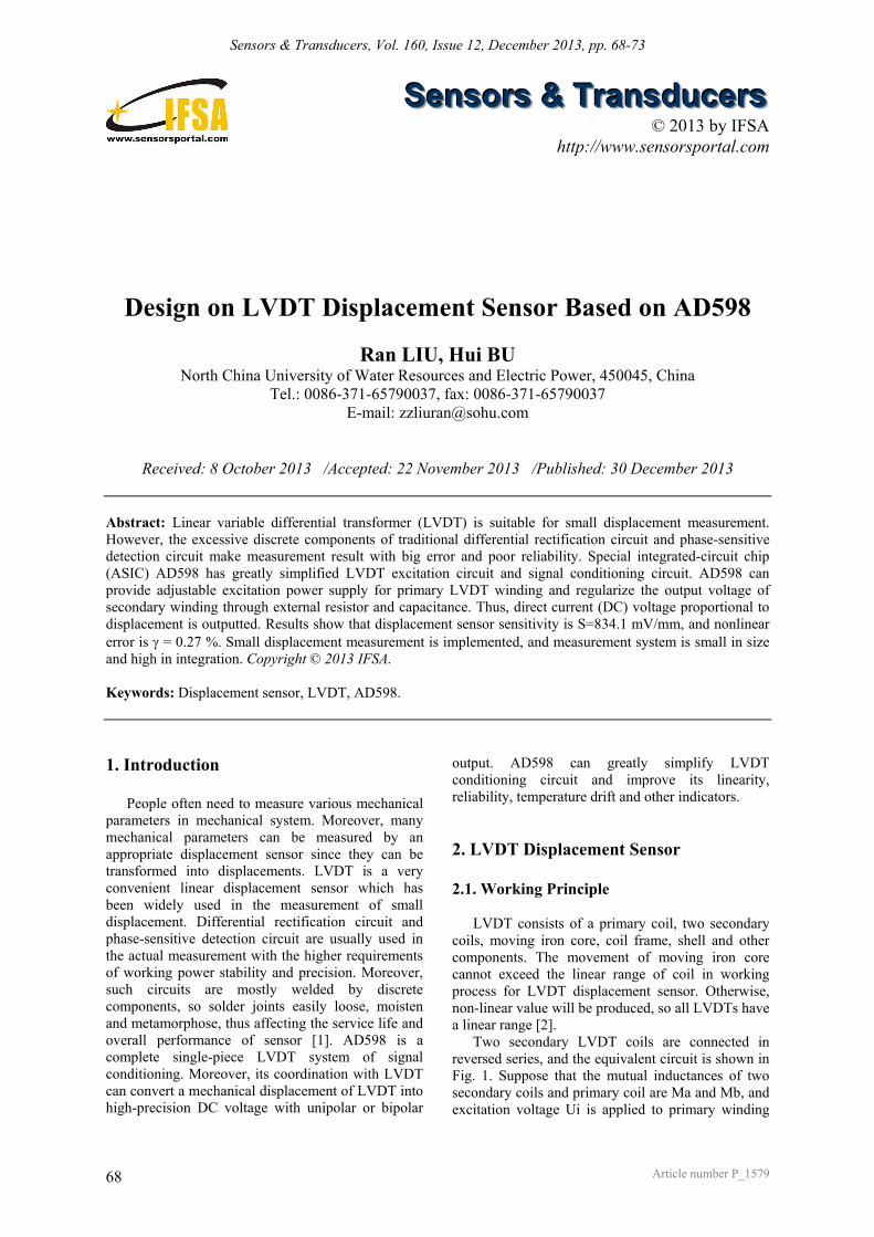
3. Internal Structure and Working Principle of AD598 AD598 consists of sinusoidal oscillator, power
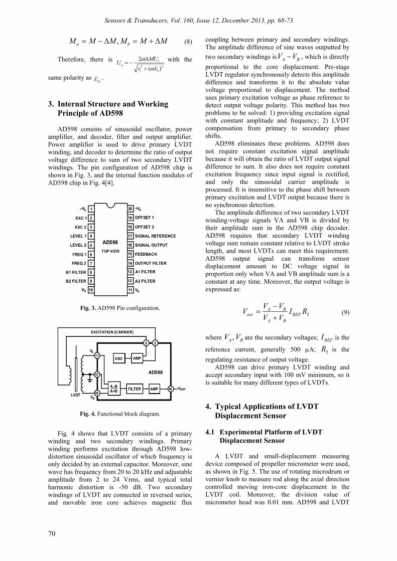
amplifier, and decoder, filter and output amplifier. Power amplifier is used to drive primary LVDT winding, and decoder to determine the ratio of output voltage difference to sum of two secondary LVDT windings. The pin configuration of AD598 chip is shown in Fig. 3, and the internal function modules of AD598 chip in Fig. 4[4].
Fig. 3. AD598 Pin configuration.
Fig. 4. Functional block diagram.
Fig. 4 shows that LVDT consists of a primary winding and two secondary windings. Primary winding performs excitation through AD598 low-distortion sinusoidal oscillator of which frequency is only decided by an external capacitor. Moreover, sine wave has frequency from 20 to 20 kHz and adjustable amplitude from 2 to 24 Vrms, and typical total harmonic distortion is -50 dB. Two secondary windings of LVDT are connected in reversed series, and movable iron core achieves magnetic flux
coupling between primary and secondary windings. The amplitude difference of sine waves outputted by
two secondary windings is A BV V , which is directly
proportional to the core displacement. Pre-stage LVDT regulator synchronously detects this amplitude difference and transforms it to the absolute value voltage proportional to displacement. The method uses primary excitation voltage as phase reference to detect output voltage polarity. This method has two problems to be solved: 1) providing excitation signal with constant amplitude and frequency; 2) LVDT compensation from primary to secondary phase shifts.
AD598 eliminates these problems. AD598 does not require constant excitation signal amplitude because it will obtain the ratio of LVDT output signal difference to sum. It also does not require constant excitation frequency since input signal is rectified, and only the sinusoidal carrier amplitude is processed. It is insensitive to the phase shift between primary excitation and LVDT output because there is no synchronous detection.
The amplitude difference of two secondary LVDT winding-voltage signals VA and VB is divided by their amplitude sum in the AD598 chip decoder. AD598 requires that secondary LVDT winding voltage sum remain constant relative to LVDT stroke length, and most LVDTs can meet this requirement. AD598 output signal can transform sensor displacement amount to DC voltage signal in proportion only when VA and VB amplitude sum is a constant at any time. Moreover, the output voltage is expressed as:
2A B
out REFA B
V VV I R
V V
(9)
where ,A BV V are the secondary voltages; REFI is the
reference current, generally 500 A; 2R is the
regulating resistance of output voltage. AD598 can drive primary LVDT winding and
accept secondary input with 100 mV minimum, so it is suitable for many different types of LVDTs. 4. Typical Applications of LVDT
Displacement Sensor
4.1 Experimental Platform of LVDT Displacement Sensor
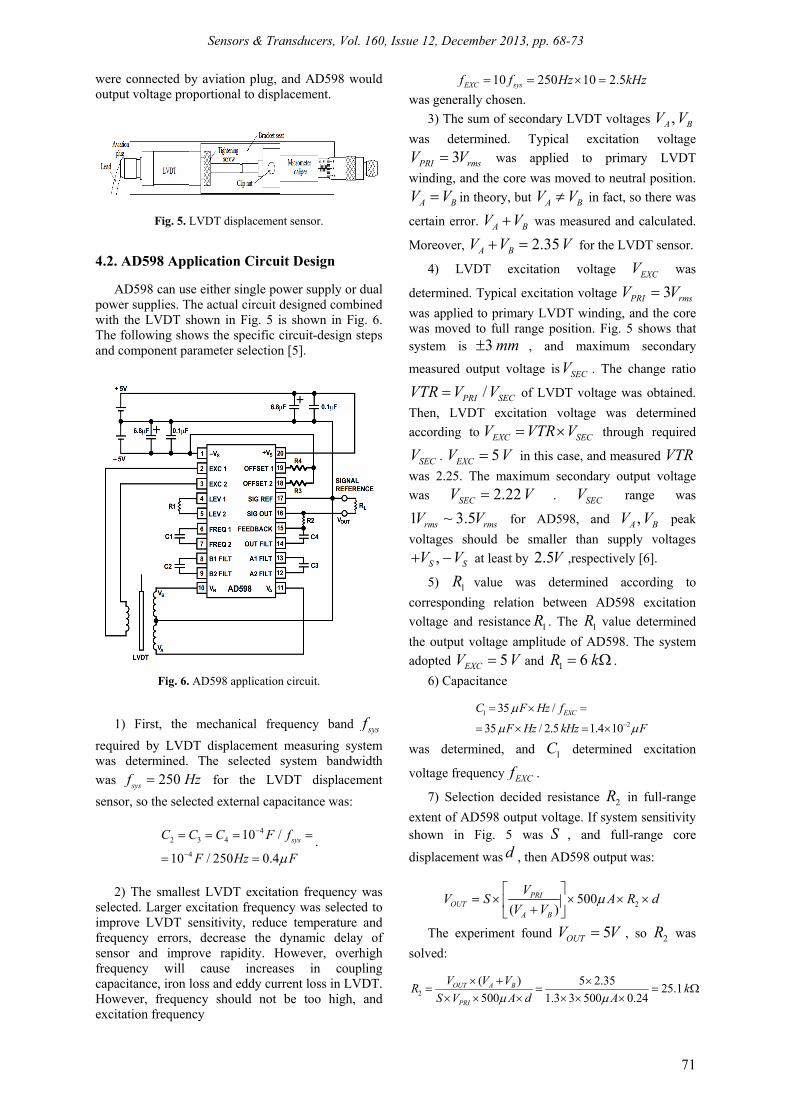
A LVDT and small-displacement measuring
device composed of propeller micrometer were used, as shown in Fig. 5. The use of rotating microdrum or vernier knob to measure rod along the axial direction controlled moving iron-core displacement in the LVDT coil. Moreover, the division value of micrometer head was 0.01 mm. AD598 and LVDT
Sensors & Transducers, Vol. 160, Issue 12, December 2013, pp. 68-73
71
were connected by aviation plug, and AD598 would output voltage proportional to displacement.
Fig. 5. LVDT displacement sensor.
4.2. AD598 Application Circuit Design AD598 can use either single power supply or dual
power supplies. The actual circuit designed combined with the LVDT shown in Fig. 5 is shown in Fig. 6. The following shows the specific circuit-design steps and component parameter selection [5].
Fig. 6. AD598 application circuit.
1) First, the mechanical frequency band sysf
required by LVDT displacement measuring system was determined. The selected system bandwidth
was 250sysf Hz for the LVDT displacement
sensor, so the selected external capacitance was:
42 3 4
4
10 /
10 / 250 0.4
sysC C C F f
F Hz F
.
2) The smallest LVDT excitation frequency was
selected. Larger excitation frequency was selected to improve LVDT sensitivity, reduce temperature and frequency errors, decrease the dynamic delay of sensor and improve rapidity. However, overhigh frequency will cause increases in coupling capacitance, iron loss and eddy current loss in LVDT. However, frequency should not be too high, and excitation frequency
10 250 10 2.5EXC sysf f Hz kHz
was generally chosen.
3) The sum of secondary LVDT voltages ,A BV V
was determined. Typical excitation voltage
3PRI rmsV V was applied to primary LVDT
winding, and the core was moved to neutral position.
A BV V in theory, but A BV V in fact, so there was
certain error. A BV V was measured and calculated.
Moreover, 2.35A BV V V for the LVDT sensor.
4) LVDT excitation voltage EXCV was
determined. Typical excitation voltage 3PRI rmsV V
was applied to primary LVDT winding, and the core was moved to full range position. Fig. 5 shows that system is 3 mm , and maximum secondary
measured output voltage is SECV . The change ratio
/PRI SECVTR V V of LVDT voltage was obtained.
Then, LVDT excitation voltage was determined
according to EXC SECV VTR V through required
SECV . 5EXCV V in this case, and measured VTR
was 2.25. The maximum secondary output voltage
was 2.22SECV V . SECV range was
1 ~ 3.5rms rmsV V for AD598, and ,A BV V peak
voltages should be smaller than supply voltages
,S SV V at least by 2.5V ,respectively [6].
5) 1R value was determined according to
corresponding relation between AD598 excitation
voltage and resistance 1R . The 1R value determined
the output voltage amplitude of AD598. The system
adopted 5EXCV V and 1 6R k .
6) Capacitance
1
2
35 /
35 / 2.5 1.4 10
EXCC F Hz f
F Hz kHz F
was determined, and 1C determined excitation
voltage frequency EXCf .
7) Selection decided resistance 2R in full-range
extent of AD598 output voltage. If system sensitivity shown in Fig. 5 was S , and full-range core
displacement was d , then AD598 output was:
2500( )
PRIOUT
A B
VV S A R d
V V
The experiment found 5OUTV V , so 2R was
solved:
2
( ) 5 2.3525.1
500 1.3 3 500 0.24OUT A B
PRI
V V VR k
S V A d A
Sensors & Transducers, Vol. 160, Issue 12, December 2013, pp. 68-73
72
8) The adjustment range of positive and negative
output offset voltage can be determined after 3 4,R R
were determined.
23 4
1 11.2
5 5OSV V RR k R k
This system circuit should be able to generate the adjustment range 0 ~ 10 ( 5 )V V of output offset
voltage. 4R was set, and 3 1.02R k was
obtained according to the above formula. Similarly,
4 1.02R k was obtained.
9) Each component parameter value was selected as follows according to actual use conditions:
1 2 3 4
1 2 3 4
6 , =25 , = =1.02 ,
=15 , 0.39
R k R k R R k
C nF C C C F
5. Sensor Test Results Table 1 shows the measured data of sensor. X is
displacement with measuring range -3.00 mm
+2.80 mm, and AD598 output voltage is OUTV with
range -2.489 V +2.339 V. Micrometer head can only adjust displacement in single predetermined direction in measurement, and callback was not allowed in midway. Otherwise, its mechanical backlash would cause displacement error. Therefore, the displacement amount of each point should be carefully adjusted, which cannot be too much. Otherwise, the point should be rejected to continue next point or return back to zero for doing experiment again [7].
Table 1. Measured data of LVDT displacement sensor.
X (mm) -3.00 -2.80 -2.60 -2.40 -2.20 -2.00 -1.80 -1.60 -1.40 -1.20
Vout (V) -2.489 -2.328 -2.177 -2.000 -1.839 -1.674 -1.492 -1.344 -1.174 -1.003
X (mm) -1.00 -0.80 -0.60 -0.40 -0.20 +0.00 +0.20 +0.40 +0.60 +0.80
Vout (V) -0.825 -0.673 -0.494 -0.321 -0.175 -0.003 +0.178 +0.329 +0.488 +0.673
X (mm) +1.00 +1.20 +1.40 +1.60 +1.80 +2.00 +2.20 +2.40 +2.60 +2.80
Vout (V) +0.837 +1.007 +1.170 +1.339 +1.501 +1.660 +1.839 +1.998 +2.174 +2.339
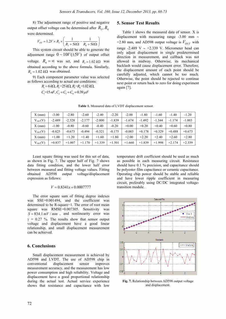
Least square fitting was used for this set of data, as shown in Fig. 7. The upper half of Fig. 7 shows data fitting condition, and the lower half error between measured and fitting voltage values. Fitting obtained AD598 output voltage/displacement expression as follows:
0.8341 0.0007777V x
The error square sum of fitting degree indexes
was SSE=0.001494, and the coefficient was determined to be R-square=1. The error of root mean square was RMSE=0.007305. Sensitivity was
834.1 /S mV mm , and nonlinearity error was
= 0.27 %. The results show that sensor output voltage and displacement have a good linear relationship, and small displacement measurement can be achieved.
6. Conclusions Small displacement measurement is achieved by
AD598 and LVDT. The use of AD598 chip in conventional displacement sensor improves measurement accuracy, and the measurement has low power consumption and high reliability. Voltage and displacement have a good proportional relationship during the actual test. Actual service experience shows that resistance and capacitance with low
temperature drift coefficient should be used as much as possible in each measuring circuit. Resistance should have 0.1 % precision, and capacitance should be polyester film capacitance or ceramic capacitance. Operating chip power should be stable and reliable and have lower ripple coefficient in measuring circuit, preferably using DC/DC integrated voltage-transition module.
Fig. 7. Relationship between AD598 output voltage
and displacement.
Sensors & Transducers, Vol. 160, Issue 12, December 2013, pp. 68-73
73
References [1]. S. C. Saxena, S. B. L. Seksena, A self-compensated
smart LVDT transducer, IEEE Transactions on Instrumental Measurement, Vol. 38, 2005, pp. 748.
[2]. R. C. De Vekey, An LVDT extensometer for tensile studies of composite materials, Journal of Materials Science, Vol. 9, Issue 11, November 2004, pp. 1898-1900.
[3]. AD598 LVDT Signal Conditioner (Analog Devices, One Technology Way, Norwood, MA).
[4]. Analog Devices, LVDT Signal Conditioner AD589 [DB/OL], http://www.analog.com, 2009.
[5]. Ara, K.: A differential transformer with temperature and excitation independent output. IEEE Trans. Instrum. Meas., IM-21, 2002, pp. 249–255.
[6]. Special Linear Reference Manual [DB/OL], Analog Devices Inc., 2009.
[7]. A. Flammini, et al., Least Mean Square Method for LVDT Signal Processing. IEEE Transactions on Instrumental. Measurement, Vol. 47, 2008, pp. 1119–1123.
___________________
2013 Copyright ©, International Frequency Sensor Association (IFSA). All rights reserved. (http://www.sensorsportal.com)