design of urban transit rowing bike (utrb) · design of urban transit rowing bike (utrb) ......
TRANSCRIPT

Design of Urban Transit Rowing Bike (UTRB)
A Major Qualifying Project Report Submitted to the Faculty
of the
WORCESTER POLYTECHNIC INSTITUTE
in partial fulfillment of the requirements for the Degree of Bachelor of Science
In Mechanical Engineering
________________ ________________ By Zebediah Tracy Claudio X. Salazar
[email protected] [email protected]
Date: August 2012
___________________________________
Professor Isa Bar-On, Project Advisor

Legend
Red: Works contributed by Zebediah Tracy Blue: Works contributed by Claudio X. Salazar
Green: Mutual works contributed by both Tracy and Salazar
Abstract The objective of this project was to create a human-powered vehicle as a mode of urban transport that doubles as a complete exercise system. The project was constrained in scope by the requirement of affordability, under $1,000. This was accomplished through reducing complexity by utilizing a cable and pulley drive train, simplified tilting linkage and electric power assist in place of variable gears. This project successfully demonstrates that rowing can be the basis for effective human powered urban transport.
Acknowledgments The UTRB MQP group would like to thank the following people for their assistance during this project. Thanks to professor Isa-Bar-On for her steadfast support and guidance over the full course of this endeavor. This report would not have been possible without her. Thanks to Derk F. Thys creator of the Thys Rowing Bike for his correspondence and for his foundational work on rowing geometry for biking. Thanks to Bram Smit for his correspondence regarding the Munzo TT linkage and his experience building a variety of innovative recumbents. Thanks to Bob Stuart, creator of the Car Cycle for his correspondence regarding his groundbreaking work and engineering insights. His experience was important to finding an appropriate project scope.

As a general rule, the human-powered vehicle community is very welcoming and open to innovative new ideas. It has been a great experience for the UTRB team to contribute to such a good-natured community.
Table Of Contents
1. Abstract 2. Acknowledgments 3. Table of Figures 4. List of Tables 5. 6. 1 Introduction 7. 2 Project Goal 8. 9. 3. Background 1. 3.1 Need for Urbanization Transport 1. 3.1.1 Modes of Human Transport in Cities 2. 3.1.2 Trends in Human Settlements 2. 3.2 Health Benefits of rowing bikes 1. 3.2.1 Cardio principles 2. 3.2.2 Body Fat Loss efficiency 3. 3.2.3 Upper + Lower body, muscular, core, and stretching benefits 3. 3.3 Physics of a rowing bike 1. 3.3.1 Principle of operation (rowing bike) 2. 3.3.2 Energy Conversion 4. 3.4 Optimal Angles 5. 10. 4 State of the Art 1. 4.1 Common Types of Urban Bicycles 2. 4.2 Alternative Bicycles for Transport= 3. 4.4 Rowing Bikes 4. 4.5 Power Assist 5. 4.6 Next Best Powered Designs 6. 4.7 Select Sub-system Technology Review 7. 11. 5 Gap Identification 1. 5.1 Rowing Bikes 2. 5.2 Tilting Trikes 3. 5.3 Gap to the main functional requirements 4. 12. 6 Proposed Design 1. 6.1 Vehicle Concept Evaluation 2. 6.2 Final Design Concept 3. 6.3 Discussion of Key Features 1. 6.3.1 Approximate Sizing and Overall Dimensions

2. 6.3.2 Rowing System 3. 6.3.3 Tilting Method 4. 6.3.4 Power Assist Sizing & Power Requirements 4. 6.4 Conceptual Feasibility 1. 6.4.1 Drive-train Power Scope 2. 6.4.2 Tilting Geometry Scope (2) 3. 6.4.3 Functional Dimensions Scope (3) 4. 6.4.4 Exercise Scope 5. 6.4.5 Safety Scope (4) 6. 6.4.6 Cost Scope (5)
7 . Subsystems, their properties and their sources
7.1 Components of the UTRB
7.2 Function for each component of the UTRB
7.3: Dimensions for the UTRB Components
8 Prototype Specification and Testing
5. 8.1 Most parts should be off the shelf 6. 8.2 Easy Assembly (in bike shop) 7. 8.3 Under 500 for raw materials + Sponsored materials 8. 8.4 Testing performance
9 Discussion
9. 9.1 What you accomplished to put together 10. 9.2 Proposed future improvements for the UTRB 11. 9.3 Comments on future manufacture at scale 12. 9.4 Suggest next steps or improvements
10 Conclusion
13. APPENDIX: 1. A. Intermediate Wants Vs. Needs 2. B Project Scope Outline Report
Table of Figures List of Tables

1 Introduction Most people today use bicycles for a combination of exercise, recreation and utilitarian transport. Bicycles provide mostly a lower-body workout which is insufficient alone as a total-body workout. On the other hand, stationary rowing is a common form of exercise that provides a more complete full-body workout with an emphasis on the upper body. If exercise is as important a focus as locomotion of the bike design, then the ideal bike is one that utilizes rowing instead of peddling as the mode of power delivery. This combination preserves the utility and recreational value of a bike while improving its exercise component by incorporating more core and arm strength in every stroke. In contract to a recumbent bicycle, where the upper body is more or less stationary while only the legs provide power, rowing bikes offer a much more complete workout. There are solutions such as the Thys rowing bike, which employs a full rowing motion on a recumbent frame, but there remain particular issues that remain unaddressed. In particular, this project focuses on solving the problems associated with using a rowing bike in the urban environment: difficulty starting quickly, discontinuous acceleration, and instability on slippery or loose road surfaces. Another focus of the design is to create a rowing bike concept that can be manufactured at a low cost. This project will evaluate the state of the art in rowing bikes and present a specific design concept that optimizes rowing bikes for urban environments. The resulting design will be a success if it is able to provide excellent mobility and exercise for its user while meeting the challenges -such as traffic, frequent stops, evading dangerous drivers- associated with biking in cities.
2 Project Goal The goal of this project is to investigate the feasibility of building a new form of urban transit rowing bike with these characteristics:
Main Functional Requirements:
• Provide excellent exercise involving all muscle groups • Price below $1000
• Safe in a lateral skid • Smooth and safe stop and start transitions • As narrow as a normal bike • Safe visibility to motorists • Safe rider roadway visibility • One day charge capacity

Desired Additional Features:
• Assist for hills, increased acceleration and consistent torque
• Acceleration equal to the maximum for a sports compact • Easy to store in currently available bike storage infrastructure
Design Philosophy: An overarching design philosophy guides this projects development. Key tenants are as follows:
• Minimize complexity to reduce cost • Use new propulsion and layout to maximize performance • Maximize novelty as a consequence
3 Background The background section is divided into three parts: one, a discussion of why human-powered vehicles will be more important in the future and some criteria that they will need to meet; two, a discussion of the physiology of exercise and the physics involved in rowing as a power mode; and three, an analysis of the ideal range of motion and geometry in rowing. This section is meant to establish the context within which urban human powered vehicles operate. The first contextual element, Need for Urban Transport, is also helpful for the design evaluation section.
3.1 Need for Urbanization Transport
Cities offer opportunities and infrastructure that are not available to rural communities; this is one reason that cities continue to grow. The developed and developing world is rapidly becoming more populous as people move into cities in order to participate in the opportunities that their density and connectivity offer. The year 2010 marks the first year that more than half of the world's population resides in an urban center and this trend is forecast to continue at a rapid pace. There are many problems that have arisen as a result of rapid urbanization and increased wealth, but one of the most striking and most costly is increasing congestion in automotive corridors. One solution to this problem is to transition to an urban transportation mix that focuses on bicycles rather than cars as the fundamental unit of point-to-point urban travel.
As cities grow they face increasing challenges in transportation. The automobile has thus far served as the underpinning of urban transport in the developed world, but, as populations grow, congestion increases threaten its utility. Almost every major city in the world loses billions of dollars per year in productivity to automobile congestion. This

problem is also linked to the obesity epidemic which has it's own set of costs. On the bright side, the Netherlands has proven that human power in the form of bicycles can be an irresistibly effective solution for urban congestion. In order to begin the process of designing a human-powered transportation system for cities in the US, it is important to evaluate the range that must be traveled.
3.1.1 Modes of Human Transport in Cities Walking. Walking is the basic form of human transportation by default. It requires no additional investment or resources and has the benefit of low-impact exercise which can improve health and productivity. The average person can walk at a speed of 2-4mph. If the maximum transit time for an individual is 30 minutes then the effective "transit radius" for walking ranges from 1-2 miles. In small and very dense cities, walking may be an appropriate means of transit but it falls short for the average city. Running and Jogging. The range of running speeds are between 6 and 10 mph for an average adult in decent shape. This translates to a range of 3-5 miles. This distance is roughly half of what is required for effective urban transportation.
Biking. The average speed of a cyclist is 14/mph but can range up to nearly 30/mph for athletes. Assuming that there is limited improvement in average cycling speeds, the maximum route distance is 7 miles. This is a perfect fit for the urban radius that has been defined below. 3.1.2 Trends in Human Settlements One consequence of dense urban centers is that distances between routine destinations are reduced within the accessible range of human power. For the analysis of human power in American cities, it is first important to establish the minimum distance that must be traveled within an average city. Based on the US Census data ending in the year 2008, the average city in the US contains roughly 3 million people. In order to cover more cities, we can double that number to 6 million for the purpose of this analysis. Now, we can use Boston, MA as a representative city in order to approximate a typical worst-case (longest) trip distance. The radius surrounding the city of Boston can be roughly estimated by tracing the travel distance from the adjacent towns of Brookline to Somerville. The distance between these two points is the longest usual route from one point to another within the metro zone. This distance is 7 miles.
3.2 Health Benefits of Rowing Bikes
The health goals for an individual using this rowing bike are to provide a complete body workout for muscle toning along with the best possible aerobic and endurance benefits. All rowing bikes are designed to provide cardiovascular benefits while simultaneously working all major muscle groups in the body more effectively than the traditional exercises of running or biking. Unlike running, rowing activates the major muscles of the back, triceps, and legs as opposed to solely the legs. Since a person on a rowing

machine expends a greater amount of energy compared to a bicycle, rowing will consequently improve a person's fitness level, provided proper rest and recovery is given in between rowing workouts. Specifically, the major physical improvements gained from rowing will be cardiovascular endurance, core strength and consequently, flexibility.
3.2.1 Cardio Principles
The UTRB is designed to incorporate an ergonometric rowing machine. When used for over a period at least 20 minutes at the intensity of 70-85% a person’s maximum target heart rate, its use will improve cardiovascular fitness and reduce body fat for the user. For full details on how a rowing bike will improve cardiovascular fitness, see Appendix A: How typical exercise rowing machines can improve cardiovascular fitness.
3.2.2 Body Fat Loss Efficiency
The greater the muscle mass of a person, the greater the calories he or she will burn per stroke, since more energy is needed to work any larger muscle group [1]. Therefore, the UTRB could be potentially used for strength training as long as a person is rowing up an inclined plane within their limits (ideally performing at most 10 -15 strokes before resting). But the only way to burn calories in a way that will shed body fat is to use the device for aerobic activity. This can be done on a UTRB when more intense resistance with the UTRB is endured for a greater period of time. For safest results, the principle of using moderate resistance for a longer period of time (over 20 minutes per session, up to 6 days a week) should be established.* * See Appendix B: The principles behind a human body burning calories for details behind how body fat can be reduced through aerobic exercise.
3.2.3 Upper and Lower Body, Muscular, Core, and Stretching Benefits
Figure 3.1 displays the core muscles in the human body. The continual motion of rowing with enough resistance works core muscles such as the hip flexors, the rectus abdominus, the transverse abdominus, the psoas major, adductor muscles, gracilis, pectineus, tensor faciae latea, and iliacus. The synergistic (complementary) muscles worked in the core are the serratus anterior muscles, and the internal and external obliques. These muscles are essential to the kinetic chain of movement of the human body. The better developed these muscles are, the higher their potential to effortlessly induce a force. Additionally, rowing will reduce postural distortion patterns in the core such as tight joints, hip and back pain.

Figure 3.1
Figure 3.2 displays the major muscles in the human body. Rowing on the UTRB will help develop the following major muscle groups in the upper body such as the latissimus dorsi, the rhomboids, the teres major, and trapezius, and quadriceps. The synergistic muscles worked in the body that are not core muscles being worked due to the rowing

movement are the triceps, biceps, gastrocnemius, peroneus longus, tibialis anterior, and other smaller muscles.
Figure 3.2
3.2.4 Comparable Cardio and Endurance Benefits of Rowing vs. Ergonometric Cycling Ergometry studies have shown that rowing exceeds bicycling in terms of its benefits for improving human peak power, lactic acid thresholds,** and VO2 max* rates. These are

three essential components for cardiovascular fitness. Figure 3.3 displays the comparisons.
* See Appendix C: What are V02 max rates in aerobic respiration?
** See Appendix G: What is the lactic acid threshold?
Rowing Cycling
lactic acid threshold improvement
Higher (as it works more muscles and strength endurance than rowing)
lower
VE,BTPS (pulmonary ventilation where body temperature pressure is saturated) higher during rowing graded
exercise test lower during rowing graded exercise test
VO2 STPD ( maximal oxygen consumption, maximal oxygen uptake or aerobic capacity under standard conditions for
temperature and pressure )
higher during rowing graded exercise test
lower during rowing graded exercise test
HR (heart rate) higher during rowing graded exercise test
lower during rowing graded exercise test
Figure 3.3
It should be noted that consistent linearity was reported to be found between VE (pulmonary ventilation) , BTPS (body temperature pressure saturated) and VO2 STPD (standard conditions for temperature and pressure) and between HR and VO2 STPD for both exercises during the tests. Results indicated that energy expenditure for rowing was significantly higher than cycling at all comparative power outputs, including maximum levels. As a result, rowing yields a greater functional value for physical fitness and exercise rehabilitation programs [2].
3.3 Physics of a rowing bike
3.3.1 Principle of operation (how to use the rowing bike)
The UTRB is a human-powered transportation vehicle that moves while rowing. As a person starts the row, his or her feet should already be slipped into the pedals of the sliding platform that is attached to the rail (the rail assembly), with their hands holding onto the T shaped handle bar lever that arcs back and forth on a fixed point on the frame. As they extend their arms forward (as is similar to the eccentric portion of a repetition

movement in a rowing exercise), their legs are drawn into the core of their body as the platform slides along the rail close to them.
To start the bike in locomotion (leading with their latissimus dorsi muscles), an individual should hold onto the T bar hand rail and draw their arms towards the core of their body. The momentum of the force generated by this movement will cause the rider’s body to recline onto the back rest of the seat while simultaneously the movement forces his or her legs to straighten out so that the sliding platform is now away from the core of his body.
When this is done, the T bar moves from one arc length to the other one as seen in Appendix B. There is a chord attached to the top right side of the handlebar called the outgoing drive cable (also known as the bungee cable, and see picture below).
This cable is responsible for pulling the rear wheel clockwise against the ground for an estimate of 2-3 radians. As this is happening, the shift cable (also known as the propulsion rope) will simultaneously perform the same function on the rear wheel that is responsible for propulsion. However, positioning of the shift cable can improve the torque (and hence the assisted power) to go up hills. Specifically, the further away the assisted cable is from the center of rotation of the rear wheel, the more torque is created.
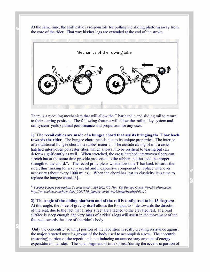
At the same time, the shift cable is responsible for pulling the sliding platform away from the core of the rider. That way his/her legs are extended at the end of the stroke.
There is a recoiling mechanism that will allow the T bar handle and sliding rail to return to their starting position. The following features will allow the rail pulley system and rail system yield optimal performance and propulsion for any user:
1) The recoil cables are made of a bungee chord that assists bringing the T bar back towards the rider. The bungee chord recoils due to its unique properties. The interior of a traditional bungee chord is a rubber material. The outside casing of it is a cross hatched interwoven polyester fiber, which allows it to be resilient to tearing but can deform significantly as well. When stretched, the cross hatched interwoven fibers can stretch but at the same time provide protection to the rubber and thus add the proper strength to the chord.*. The recoil principle is what allows the T bar back towards the rider, thus making for a very useful and inexpensive component to replace whenever necessary (about every 1000 miles). When the chord has lost its elasticity, it is time to replace the bungee chord.[3].
* Superior Bungee corporation: To contact call: 1.256.259.3770 How Do Bungee Cords Work? | eHow.com http://www.ehow.com/how-does_5005719_bungee-cords-work.html#ixzz0xgP63s10
2) The angle of the sliding platform and of the rail is configured to be 13 degrees: At this angle, the force of gravity itself allows the footpad to slide towards the direction of the seat, due to the fact that a rider’s feet are attached to the elevated rail. If a road surface is steep enough, the very mass of a rider’s legs will assist in the movement of the footpad towards the core of the rider’s body.
Only the concentric (rowing) portion of the repetition is really creating resistance against the major targeted muscles groups of the body used to accomplish a row. The eccentric (restoring) portion of the repetition is not inducing an unnecessary amount of energy expenditure on a rider. The small segment of time of rest (during the eccentric portion of

the repetition) is just enough to allow a person to restore their ATP stores* and catch their breath while still inducing an aerobic state on the body.
Within the components of the UTRB, the outgoing cable line and the shift cable are primarily responsible for the recoil mechanism on the bike and specifically the shift cable determines gears and torque assistance for the rider. * See Appendix E: How ATP stores are restored in a person’s system for exerting energy.
3.3.2 Energy Conversion
Maximum energy output (top speed, 30% grade, max power assist)
On average, the maximum amount of activity output that a human can produce from rowing on a flat surface is about 35 strokes per minute (SPM). We demonstrate the physics of how at this near maximum state of constant rowing, the amount of energy and power can be calculated.
The amount of strokes performed in one minute determines how much power can be produced from the act of rowing. Power is the amount of energy that is expended per unit time, flowing from its potential form to kinetic form. Energy that is being expended and transformed from one kind of energy to another kind within a system over an amount of time is described by the equation:
2
3
dE N m kg mdt s s
⋅ ⋅℘= = =
Where ℘= the power dE = the amount of energy that is exerted/expended over time, and dt = that time, N = Newtons of force, kg = kilograms of mass and s = seconds In this case, if we consider the amount of mechanical energy a person can input on the UTRB in the standard of say, one minute, there are two variables that must be taken into consideration: The first variable: Understanding the strokes per minute, pace, and power output principles in rowing. Most rowing bikes’ power output are simply measured by the amount of strokes a person can thrust out in one minute. As mentioned in the previous section, this unit of

measurement, basically confined to the interests of row boating and crewing races is
known as a person’s strokes per minute, Sm
, or strokes per second. (For this report, we
will focus on using Sm
for simplicity). While this means for measuring performance is
acceptable in rowing, a more accurate means for measuring power is by calculating an individuals pace, and then using that result to further calculate the power output from rowing. The pace of an individual rowing can be calculated by the equation:
( )(in seconds)a
distance in meterstimeP ce =
The power output in watts can be calculated by:
3
2.80= power (in watts) = ap ce
℘
Where 2.80 is a constant used in ergometry calculations for rowing [9] The second variable: Calculating the magnitude of power produced per minute and expended by rowing. Regardless of how many strokes a person can pump out on average in one minute, the amount of resistance that a person will have to overcome in order to perform the stroke determines the power output the mechanical energy of the rider can bring to turn the wheels below. For instance, consider a person on a rowboat rowing through a relatively non viscous medium that the oars could stroke through, such as water. Then, consider the same situation occurring in a medium that is thicker than water, such as ketchup. The oars would require greater force from the user in order to perform the stroke. In the same way, the more resistance existing against a rider, the greater the amount of energy expenditure she will need to exert in order to perform the stroke. Despite their efforts, their power output ( that is, how much energy is modulated on the actual UTRB itself) will not be high. To calculate a person’s energy expenditure by rowing, we use the following example: Based on International Steam Table (1956) [7] 1 calorie is defined to be exactly 4.1868J. With that reference in mind, consider that the amount of calories burned by a person through rowing under conditions of minimal resistance of rowing on a flat surface is relative to the individual.
Consider for example a 35 year old woman who is 5”4 weighing 135 pounds. The amount of calories she would be burning through rowing would be 8.9 calories per minute [8]. In terms of her energy expenditure:
( )8.9 4.1868 37.26521 min 1 min
j jdEdt
×℘= = =
Where dE = the amount of energy that is exerted/expended over time, and dt = that time. For details on the math, see Appendix H: Math Calculations To calculate the power output a rider can bring on the UTRB to turn the wheels below, independent of their proportions, suppose the rider was able to row 100 meters in 90 seconds. Her power output to move the UTRB would be:
( )(in seconds)a
distance in meterstimeP ce =
The power output of the rider in watts would be calculated by:
3
2.80 2.80 = = 3.84087791 watts0.9 0.729
℘ = [9]
In the case of a UTRB, the typical ‘resistance’ a rider will encounter comes in the form of air friction and gravity working against the user to stroke properly. In order to overcome this resistance, the UTRB, like other traditional bikes, could be further designed to come with a set of gears to assist in outputting more power. In the case of a bicycle, the power comes in the form of a gear that facilitates the ability to move the pedals. Of course, in the case of the UTRB, the power comes in the form of a ‘gear’ that will facilitate the ability to perform the stroke. This would come from adding more torque assist by setting up the pulley system in a way that assists the mechanical movement to go against natural resistance. The added proposed design for including an electrical assist to output more power are not included in this report.
3.4 Optimal Angles

The mechanics behind rowing consist of inversely drawing in the extended limbs to the core upon every stroke. For doing this with greatest ease, the rail and seat should be positioned at minimum elevation, which will allow a rider to work every muscle homogeneously for greater lengths of time. The reason for this, as it turns out, is that while any change in elevation of either the rail or seat may benefit developing certain muscles, it will eventually cause these muscles to develop lactic acid buildup quicker, thus causing the rider to have to stop and rest more frequently between rounds. It has been calculated that the optimal angle for the rail should be 13.284 degrees*.
*Note: See Appendix F -- the principles for determining the most optimal angles for performing ergonometric movements for more details on calculating the optimal angles for rail and elevation design for the UTRB
4 State of the Art There is substantial diversity among modern bicycle designs and the following is an attempt to catalog the major categories along with detailed examples from important classes. Each item identified in this state of the art will be supported by an explanation describing its key features and associated benefits. The final element of each item is a subjective assessment of performance rated 1-10 followed by a rough measure of complexity; the final filter is based on how novel and compelling the design is. These numbers will be helpful quantitative guides in subsequent design decisions.
4.1 Common Types of Urban Bicycles
1. Single Speeds
Image Source: http://www.mapmyride.com/community/groups/683124160812266427 Unique properties:
• no gear shifter • conventional road frame • flat handle bar • with or w/o fixed gear • with or w/o brakes • Most popular type
Price: $800-$1,000

2. Used 'vintage' road bikes
Image Source: http://www.vintage-trek.com/Trek_galleryKM.htm Unique properties:
• 10 Speed and up • Steel frame construction • Very popular
Price: $250‐$400
3. Cruiser Bikes
Image Source: http://ab-bike.com/info_steel-city-bike.html
Unique properties:
• Designed for style • Upright seat position • Larger diameter tires • Heavy frame
Price: $500-$700
4. Electric Bike (e-bike)

Image Source: http://www.china-ebikes.com/en/Products.asp Unique properties:
• Electric Motor • Battery • Power Controller • Top speeds 25mph • 30M in China
Price: $650 (estimate)
The price range for the most common urban bicycles is $500-$800, while used or 'vintage' bikes can run as low as $250. In order to charge a higher price, an alternative product would need to have impressive advantages over traditional systems. One advantage of common urban bikes is that they are very narrow. These bikes are all able to fit easily in narrow bike lanes, be stored at bike-racks and on sidewalks, and slip between cars in traffic. The narrow track of these bikes is a major benefit. The final criterion that makes these bikes valuable is that they are very maneuverable, because riders can bob and jive their center of mass in order to avoid obstacles. This flexibility is one of the reasons that it is possible for experienced riders, for example, to balance on two wheels while waiting at a stop light. Although cyclists who can balance are able to start more quickly than other riders, even riders who are unable to balance at a stop can get a rolling start by pushing off the ground prior to the first stroke. This initial velocity is helpful because it allows the rider to make course corrections to prevent tipping over immediately following the start.
The primary drawbacks to all of the common bike types are that they do not provide full-body exercise, and that they have a complex gearing system that can degrade in the elements. As with all bikes, there is a maximum amount of power that can be delivered to the wheels because the rider is not able to push against anything aside from his/her body weight. Despite these drawbacks, these bikes are the state of the art for urban

human-powered vehicles and, as a mode of transit, they are on the rise in major cities from Boston to Shanghai.
4.2 Alternative Bicycles for Transport
5. Traditional Recumbent
Image Source: http://teacherontwowheels.com/2008/06/06/recumbent-riding/
• Long chain drive-train • Efficient power delivery • difficult to start
Price: $1,000 6. Covered "Streamlined"
Image Source: http://www.wired.com/culture/lifestyle/news/2007/03/bikerecord_0330
• Speed record (81mph) • Straight, flat roads only • Can't start without helpers

Cost: $2,000
7. Two Front Wheels ("tadpole" Trike)
Image Source: http://www.utahtrikes.com/TRIKE-CTVILLAGER.html
• Stable in slippery conditions • Easy to start from stop
Price: $1,600
8. Two Back Wheels ("delta" trike)
Image Source: http://www.besportier.com/archives/gomier-electric-powered-tricyc.html
• Can tip while breaking in turns • Bulky
Price: $350 9. Velomobile (car-cycles
Image source: http://www.velomobiles.net/buying/buying.html#vmnl
• Covered 3 wheeler • 2 front wheels

• Higher speed than open version • difficult to enter-exit
Price: $4,000-$10,000 In contrast to the most common urban bikes, recumbent and high-performance three-or-more wheeled bikes are much less common and more expensive. The market for these vehicles is mostly contained within the recreational sector, although some people use these vehicles for commuting. Each alternative type of vehicle listed above has a unique set of advantages and disadvantages. Far and away the biggest drawbacks are price and basic compatibility with urban situations like frequent stops and narrow bike lanes. 4.3 Tilting with 3 or more wheels
10. Tripendo HPV
Image Source: http://www.tripendo.com
• Hand lever tilting • Hand lever steering • Carbon Mono-body • 4 bar suspension linage w/ tilting mechanism • Full-size wheels
• Price: $3,000 (and up)
11. Munzo TT
Image Source: http://www.fastfwd.nl/

• Rear swing-arm tilting • Single suspension shock • Composite rear wheels • Width no wider than rider • Detachable front section
Price: $2,000 (estimate)
12. Apex hydraulic
Image Source: http://apax.ca/
• Extraordinarily smooth • Heavy/complex hydraulics • Narrow Width
Price: $3,000 (estimate) 13. Black Max
Image source: http://www.fleettrikes.com/blackmax.htm
• Very fast cornering • Like Munzo TT but with parallelogram linkage. • No suspension
Price: $1,000 (estimate) 14. Jet Trike

Image Source: http://jetrike.com
• Integrated tilting and leaning design • No suspension • Open-Source Design
Price: $1,000 (estimate) These tilting trike designs are unique because they blend the stability advantages of three-wheeled models with the performance and lighter construction of two-wheeled models. In the case of the Tripendo and the Apex, the performance of each is unique, including very agile turning response and smooth riding on stairs, respectively. The Munzo TT design is very simple, light, stable and narrow, effectively blending the positive aspects of bikes and trikes but without any new abilities. In order to create a tilting trike that is cost-competitive with incumbent urban bikes, it is most important to identify simple solutions with few parts. The Munzo TT design fits this description and its novelty (only 2 instances were found) make it a very interesting technology. The Black Max design is also unique and offers very high performance and low complexity but lacks a suspension system; a second drawback is that there is no easy place to mount motors.
4.4 Rowing Bikes
15. Thys Rowing Bike
Image Source: http://rowingbike.com/site/EN/
• Stationary Center of Gravity • Lines don't rust and last longer • Unique spiral pulley gearing system • Steering & rowing combined in handlebar • Price: $4,400
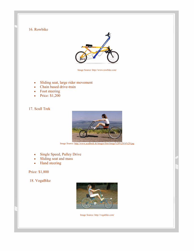
16. Rowbike
Image Source: http://www.rowbike.com/
• Sliding seat, large rider movement • Chain based drive-train • Foot steering • Price: $1,200
17. Scull Trek
Image Source: http://www.sculltrek.sk/images/foto/image%20%2816%29.jpg
• Single Speed, Pulley Drive • Sliding seat and mass • Hand steering
Price: $1,800 18. VogaBike
Image Source: http://vogabike.com/

• Cable-chain hybrid • Stationary rider mass • Complex pulley and linkage power delivery • Price: $2,000 (estimate)
Rowing
Image Source: http://www.greatoutdoors.com/published/rowing-the-other-paddle-sport The rowing motion employed on a scull is the inspiration for each of the above designs. The most important difference among the designs is whether the rider's body or limbs are in motion. For the Rowbike and the Scull Trek the body of the rider oscillates back and forth in the same way that an actual scull operator does. This approach has the major disadvantage of making vehicle handling characteristics unpredictable. An additional disadvantage is that the rider's body mass causes much of the energy to be used without adding to locomotion. The principle difference between the VogaBike and Thys RowingBike is that the former employs a chain and traditional bike transmission while the latter utilizes an original 100% pulley and line drive. The Thys drive-train is simpler, lighter and proven to be more durable than chain-based drive-trains, and is thus superior.
4.5 Power Assist
18. Green Wheel
Image Source: http://www.altwatch.com/green-wheel-the-future-of-electric-bikes/
• Integrated Single Unit (motor, battery, controller) • Lower Performance

Cost: $350 (estimate) 20. Geared System
Image Source: http://pedaleconomics.blogspot.com/2006_10_01_archive.html
• Highest Power • No added rolling mass • Design flexibility • More moving parts (chain, gear)
Cost: $400-$1000 21. Hub Motor
Image Source: http://www.electricbikeshed.co.uk/shop/electric-bicycles/oxygen-bikes/oxygen-emate-explorer.html
• Simple power delivery • Rolling mass added • The price is trending down w/ scale mfg.
Cost: $500 22. Two Stroke Engine
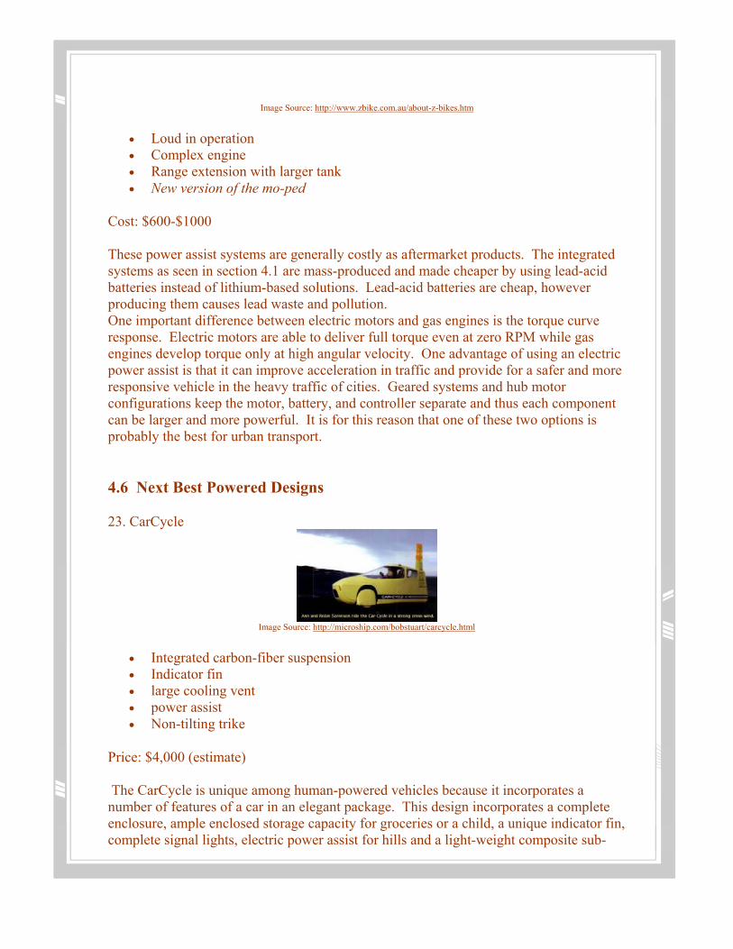
Image Source: http://www.zbike.com.au/about-z-bikes.htm
• Loud in operation • Complex engine • Range extension with larger tank • New version of the mo-ped
Cost: $600-$1000 These power assist systems are generally costly as aftermarket products. The integrated systems as seen in section 4.1 are mass-produced and made cheaper by using lead-acid batteries instead of lithium-based solutions. Lead-acid batteries are cheap, however producing them causes lead waste and pollution. One important difference between electric motors and gas engines is the torque curve response. Electric motors are able to deliver full torque even at zero RPM while gas engines develop torque only at high angular velocity. One advantage of using an electric power assist is that it can improve acceleration in traffic and provide for a safer and more responsive vehicle in the heavy traffic of cities. Geared systems and hub motor configurations keep the motor, battery, and controller separate and thus each component can be larger and more powerful. It is for this reason that one of these two options is probably the best for urban transport.
4.6 Next Best Powered Designs
23. CarCycle
Image Source: http://microship.com/bobstuart/carcycle.html
• Integrated carbon-fiber suspension • Indicator fin • large cooling vent • power assist • Non-tilting trike
Price: $4,000 (estimate) The CarCycle is unique among human-powered vehicles because it incorporates a number of features of a car in an elegant package. This design incorporates a complete enclosure, ample enclosed storage capacity for groceries or a child, a unique indicator fin, complete signal lights, electric power assist for hills and a light-weight composite sub-

frame. In it's day this design was among the best velomobiles and demonstrated a number of unique technology concepts that are relevant for all human-powered urban transit designs. It was never produced for lack of funding and fleeting public interest. 24. RunAbout Cycles
Image Source: http://www.electric-cycle.com/html/runabout_0.html
• Large electric power system • Heavy wheels designed for downhill MTN bike racing • Heavy 2.5" heavy-duty tires • Robust steel frame • Non-tilting trike
Price: $6,000 RunAbout Cycles has been a successful small company producing a high-performance powered trike that is safe in the traffic of a small-sized city because of it's robust construction and high power. This bike is capable of rapid acceleration at stop lights and, since it doesn't tilt, is very stable and maneuverable. The primary drawbacks are that it is very heavy and expensive on account of its robust construction and high power. The RunAbout Cycles trike is unique among powered trikes in that it has been a commercial success. 25. Tripendo w/ motor kit
Image Source: http://tripendo.com/
• Tilting tadpole design • Independent suspension • 3x 26" Wheels • Lever tilt & steering control

• Tilting trike
Price: $6,000 The motorized Tripendo is a very elegant and agile machine despite the complexity of it's design. By employing independent tilting and steering controls the bike is capable of quick turns that are not possible with a 2 wheeled alternative. The powered Tripendo is wider because it utilizes the 'tadpole' layout configuration but this also makes it more stable and safer. As with the other two top designs, the Tripendo with power assist is many times the budget of a typical urban cyclist and is unlikely to ever become a widely-used mode of urban transport. Each of these powered three-wheeled designs are very effective in the context of the design objectives and applications for which they were built. Since this project is to design a rowing bike, there is clearly a wide gap between the best cycle concepts and the best rowing bike.
4.7 Select Sub-system Technology Review
The prior sections have described the prior art in on an individual basis. The following table is a comparison of several important subsystems to provide additional clarity to the analysis of the gap between existing technologies and an idealized design. Sub-System Technology One Sub-System Technology Two
Tilting Tadpole Trike:
• Very stable • Simple chain drive geometry • complex tilting geometry • complex suspension
Tilting Single Front-wheel Trike:
• Less stable in unexpected lateral slides
• More aerodynamic potential • Can be made to be narrow
Parallelogram Tilting Geometry:
• Smaller vertical dip • Deep tilting angles possible • Complex suspension design is
expensive
Swing-Arm Tilting Geometry:
• Larger vertical drop in turns requires careful design
• Swing-arm length limits maximum tilting angle
• Wheelbase widens in turns • Very simple suspension design,
proven

Cycling:
• Well-established technology • Smooth power delivery for
acceleration • Leg-only exercise, esp. for
recumbent
Rowing:
• Simple cable-pulley drive • Discontinuous power delivery • Full-body workout
Tilting Trike:
• More comfortable at speed • Lighter components • Requires more rider skill • Can be narrow at slow speed
Static Trike:
• Fail-safe construction • large bending moments induced
while cornering require heavier construction
• Wide frame required
Two Dimensional Frame:
• Automated manufacturing • Fewer manufacturing operations • Can use composite materials which
are getting better over time
Aluminum, Titanium or Steel Tube Frame:
• Requires a number of welding steps • Good structural welds require
expensive expertise • Metals are finite and in high demand
for buildings, aircraft, trains and will become more costly in time.
Chain-Motors:
• Large motors can be used • Motor mass closer to vehicle center • Many models and vendors
Hub Motors:
• Theoretical design • Simple and can become cheap • Easily integrated with any final
design
Separate Batteries:
• Large energy storage possible • Easy to replace older batteries • High energy flow possible
Hub Batteries:
• Limited total energy storage • Limited energy flow rate
5 Gap Identification

This discussion will assume the starting point of the Thys Rowing Bike design as the most mature and refined art in the rowing bike category.
5.1 Rowing Bikes
The verity of bikes present different solutions for specific contexts. Rowing bikes were developed primarily in the context of exercise and recreation and although they meet their desired intent they fall short as effective urban transportation. The following is a list of aspects that must be improved.
• 2 wheeled configuration is not safe for start from a red light (see tilting) • Discontinuous power delivery causes irregular handling in hills and while
accelerating • Instability on slippery surfaces causes crashes which result in visibly scrapped
thighs of Thys racers • The drive system requires the design of a unique spiral pulley which drives up
cost • The high tolerances required to build the track system employed in Thys increases
the cost • Aluminum construction requires welding and human time, true throughout the
bike industry. Companies are able to employ robotic welding equipment only after reaching high volumes.
• The foot pulley is complex because it needs to be large so that it can double as a spool in the gearing system. This is another component that must be custom made with high tolerances.
5.2 Tilting Trikes
In order to address the instability of rowing bikes like Thys, a tilting trike layout is desired. Tilting trikes present the unique features of being stable like a car while leaning into corners like a bike and have been developed primarily for recreation and as a technical hobby. Although the state of the art in tilting trikes is impressive and several have won awards the following items must be addressed in the urban context.
• Tilting trikes are very expensive due to their complex and use of custom parts • The Munzo TT design employs a simple linkage but requires many welded joints
and would therefore require many unique manufacturing operations which is intrinsically costly.
• The Munzo TT design is too low to be safe in the city although this increases it's speed. If the seat is configured in more of an upright position this issue would be taken care of.

5.3 Gap to the main functional requirements
High-quality exercise Thys and all rowing bikes
Price under $1000 urban bikes and traditional trikes (#8) only
Safe in a lateral skid All tilting trikes and 'tadpole' trikes
Smooth and safe stop and start transitions All trikes
As narrow as a normal bike All 2 wheeled and only 'delta' tilting trikes
Visible to all motorists Urban bikes, all others with signal flag mounted
Safe roadway visibility All art except the very low: #6, 7, 11, 13, 14
Full day of charge RunAbout Cycles, Tripendo Electric We will use some of the characteristics of rowing bikes, tilting recumbent trikes and power assist systems and integrate them in a way that will best suit our specific application and context, namely the urban transportation environment.
6 Proposed Design The previous sections of this report have been dedicated to evaluating the landscape of human powered transport in cities and different types of bicycles that have been created. Despite the fact that many bike designs were omitted there are still 25 very unique bike types documented in this report. The sheer volume of prior art presents an opportunity to recombine all of the best ideas into a single (better) design.
6.1 Vehicle Concept Evaluation
• Munzo TT + Thys Drive + Single Speed (Skull Trek) + Flat Composite Construction + Power Assist
o This design is far and away the most simple and thus can be the most cost-effective. It can also be made to be very light weight by integrating the seat with the frame structure
• Thys spiral CVT + Munzo TT + Thys Drive + Power Assist o This is a close contender but for the sake of cost savings it should be
eliminated from the design and it's function replaced by a more robust power assist that can quickly accelerate the vehicle to cruising speed.
• Tripendo + Thys + Single-Speed + Power Assist o Great handling but complex and wide

• Rowing recumbent with training wheels that descend in turns and at low speed o poor take-off acceleration, complex operation, failure risk
• Low tadpole trike + electronic power assist + wrap-around seat (T-Rex) o heavy and wide
• Long tilting arms in the front + rear wheel drive + rear wheel tilting + rowing drive
o complex and heavy front end • Tilting front and flat back section with smaller tires
o this design would need to be heavy to be safe in turns • Hydraulic drive + Thys rowing + Electric assist
o Hydraulics are heavy and inefficient • Thys drive + Electric Assist + Hydro-pneumatic suspension & tilting + Munzo TT
seat/wheel/handle geometry o This concept is promising although the hydraulic tilt control components
are not mature and, on the basis of pictorial analysis alone, appear to be heavy industrial hydraulic components. From the video
6.2 Final Design Concept proposal
The following is the list of features that embody the best ideas from other attempts combined into one vehicle.
A. Thys Rowing Bike geometry (Stationary rider, pulley and line based drive train) B. Munzo TT, rear swing-arm tilting system and integrated suspension C. Front wheel drive using line-pulley assembly inspired by the Thys Rowing Bike D. The rear wheels are driven from two independent electric motors. This
configuration allows each rear wheel to provide power to accelerate while in a turn when each wheel must have a different angular velocity.
E. Single-speed line-pulley configuration (to reduce complexity & cost) F. Fiber (carbon/glass) composite main structure with aluminum fittings. Instead of
welded steel or aluminum segments that are only -strong enough if welded by experts-- the frame can be made as a single piece of high strength composite. If the design utilizes a flat frame concept where the frame is laser cut and assembled using standard fillers and fasteners then the front rail support, seat and all of the mounting pints for other parts can be made to be light and inexpensive. In time, composite materials will become increasingly cost effective as new carbon-based materials are invented. In the case of metal frames, the base metals are a scarce commodity and will only become more expensive in a world with increasing population.
G. Externally sourced power assist (2x0.5hp motor-10lb, large battery-10lbs, power controller)
H. All breaks, fasteners, cables, tires and other parts not mentioned are standard bicycle parts
I. Signal tower like the CarCycle but with a rear and forward mounted camera similar to modern cars

Core Requirement Review High-quality exercise A, Full body rowing exercise
Price under $1000 B, C, E & F, aim to reduce cost
Safe in a lateral skid B, the tilting trike is stable without traction
Smooth and safe stop and start transitions B, since Munzo TT is a trike geometry
As narrow as a normal bike B, Munzo TT is very narrow
Visible to all motorists I, Signal tower improves visibility at night and during the day
Safe roadway visibility I, Cameras mounted on the signal tower improved long-range visibility
Full day of charge G, power assist sizing to match this requirement
Supplemental Requirement Review
Power assist for hills & consistent torque
This is provided because larger motors and batteries were chosen instead of multiple gears. This also satisfies the design philosophy of reduced complexity
Acceleration equal to the maximum for a sports compact
The choice to utilize a larger power plant mans that the vehicle has very high rates of acceleration and traditional bikes with similar power accelerate faster than most cars
Easy to store in currently available bike storage infrastructure
The use of the Munzo TT tilting linkage results in a reduced width so that the vehicle can fit on standard bike paths. The fact that it is a 'delta trike' with only one wheel makes it compatible with the established infrastructure of bike racks.
6.3 Discussion of Key Features (proposal)
Before delving into the detailed design and prototyping specifications for this project it is important to review several key features features of the design such as the approximate sizing, rowing operation, tilting method and power assist sizing.
6.3.1 Approximate Sizing and Overall Dimensions

The Tripendo, Munzo TT and Thys Rowing Bike were all designed for riders of average size and weight because each are intended for public use. In the case of the Tripendo, the maximum rider weight is specified at 120kg (265lb) and height of between 5.5 feet and 6.5 feet. These rider characteristics conform to the average sizes and weight of people in the US and can be used to evaluate the approximate size of the UTRB vehicle. The ideal production process will accommodate for custom sizing each bike to fit it's intended user precisely but for the purposes of an overall analysis the above assumptions will be used.
Image Source: Own Work The overall dimensions of the UTRB will fall within the range of existing recumbent bikes while being somewhat slimmer than recumbent trikes such as the Tripendo (see reference figure I). The Tripendo has the following specifications: 86 x 39 x 34 inches. This vehicle will have the same overall length of 85 inches (7.2 feet) and a seat height no higher than 39 inches (3.25 feet). As a point of reference, the original 1960s mini cooper is a very small car and is 4.4 feet tall (see reference figure IV). Although the Tripendo is high enough to be operated safely in traffic with a head height over 3.25ft, the Munzo TT is too low to see or be seen at roughly 2.5ft. The advantage of having a lower head position is a lower cross-sectional area and reduced bike drag. In order to take advantage of the reduced drag of the Munzo TT while providing adequate safety and visibility like the Tripendo, a signal tower must be implemented. The CarCycle employed a similar signaling method and somewhat demonstrated the feasibility of such a solution. As a matter of approximate sizing of 3.25ft will be used because it represents an upper limit for the vehicle's drag and material stress. Both of these upper limits are important when evaluating other facets of the design. The ideal width of the vehicle would mirror that of the Munzo TT of roughly 16 inches (1.3 feet) because it is very slim while being stable fully tilted (see reference figure II). In order to make the design consistent with the above assumption that the vehicle will be scaled up by the same factor in order to maintain the same relative geometry. The

following calculation is used (3.25ft/2.4ft)*1.3ft = 1.75ft. This new dimension will be used to approximate material requirements among other elements. The wheel dimensions required to operate the Munzo TT design are 20 inches in diameter and require the use of standard road tires for that same size (see reference figure III). The drawback to smaller wheel diameters, in contrast to the 26 inch standard for road bikes, is that they provide a bumpier ride while they are stronger and can hold up to harsher road conditions. In contrast to most road bikes, the UTRB employs a suspension system in order to absorb these shocks and there should be no net increase in ride roughness due to the smaller tire diameter employed. As a comparison, the Vespa scooter has 10 inch wheels and is used heavily for urban transport which further supports the idea that 20 inch wheels are perfectly adequate.
Section 6.3.1 Reference Figures
I) Tripendo side view for height reference
Image Source: http://www.tripendo.com
III) Munzo TT side view for wheel size reference

Image Source: http://www.fastfwd.nl
6.3.2 Thys Rowing System (a proposed design)
The Thys rowing geometry is unique among rowing bikes because it contains no chains and maintains a stationary rider center of mass. The Thys rowing drive-train has two important elements: one, the forward block and pulleys or 'foot swagger'; and two, the spiral drive pulley mounted to the drive wheel or 'Snek'.
Front Assembly (see figure I) The foot swagger has two main functions in the most recent design of the Thys drive-train. The first function is to incorporate power developed from the motion of the arms and the motion of the legs into a single cord. This is accomplished by converting the linear motion of the arms and legs into rotational motion on a single axle and then converting the result back to linear motion. In this way the work done by the arms and legs is added without requiring that both actions happen at the same time or that they have the same travel. The second purpose of the foot swagger is to store or spool excess drive-line which is used to operate vehicle gearing. Rear Assembly (see figure II) The rear assembly utilizes extra cord that is stored in the foot swagger system in order to move line onto and off of a specialized spiral drive pulley. By moving the excess cord back and forth between the rear Snek and the foot swagger a rider is able to change the active diameter of the drive pulley. More precisely, as more cord is spooled onto the Snek the drive cable is forced to climb further along it's windings and this means moving into a wider diameter region of the spiral pulley. The exact workings of the clutch

mechanism that makes this spooling in and out possible are less complex than a traditional bike derailleur making the whole gearing concept a very elegant. Thys Rowing Bike Drive-Train Figures I) Thys Front Assembly II) Thys Rear Assembly
Image Source: http://rowingbike.com/site/EN/Models/Thys-222-Revolver/pnCurrent:2/
Image Source: http://rowingbike.com/site/EN/Models/Thys-222-Revolver/pnCurrent:3/
Simplification for the UTRB One drawback of the particular way that the Thys design accomplishes this goal is by having the peddles and pulleys mounted on the same track. Although this seems to integrate two functions into a single element it also creates the need for the slider rail to be very tough so that it can withstand moments generated by uneven application of leg power. The precision required to construct the Thys rail would cause it to be too expensive for this design objective. This can be achieved by mounting the peddles to a bar that rolls along the top surface of the front support. The double pulley could then be mounted at a different location on a light-weight track that would only need to counter-act slight moments generated by the mass of the components themselves. Instead of utilizing the complex Snek design, the UTRB will utilize a single speed and thereby reduce the cost of the mechanical elements of the drive train. These cost-savings are possible because of the powerful electric assist which will provide adequate acceleration for safe operation in the urban environment regardless of skill-level.

6.3.3 Tilting Method
There are two primary ways to create a tilting three wheeler. The first is a four-bar parallelogram linkage similar to that used in modern car suspensions but modified for tilting. The other design is the swing-arm linkage concept where tilting is achieved by the arms moving in opposite directions along a common pivot point. The most important reason to select the swing-arm design is the very low parts count required to create a full-suspension version. The Munzo TT only has 7 linkage parts and a single shock absorber. The minimum complexity of a parallelogram is 7 with two suspension elements (as seen in the Tripendo below).
Tilting Methods Table Parallelogram Tilting Swing-Arm Tilting
Image Source: http://www.tripendo.com/EDEFAULT.htm
Image Source: Own Work & http://www.fastfwd.nl/
6.3.4 Power Assist Sizing & Power Requirements (theoretical addition to the UTRB)
There are a number of drivers for the power assist specification. They are as follows:
• Maximum acceleration (comparable to 8 second 0-60 or 11ft/s^2) o A 1hp (745 watt) motor is more than enough to accelerate a 50lb vehicle
with a 250lb person at 11ft/s^2. • Maximum operating power • Replacing human power during recovery stroke • All-day use without recharging

Range: Battery Sizing The average person living in Boston travels a maximum of 7 miles to and from work and an additional 26 miles at a maximum after work running errands, meeting friends and on other activities. This would suggest a maximum week-day trip distance of 40 miles. Weekend travel range requirements can be somewhat higher. If we assume an average weekend activity time of 2 hr and an average tip length of 7 miles, plus an average of 12 active hours in a day then you arrive at (12/2)*7 or 42 miles as the maximum weekend trip length. These very rough estimates establish the maximum distance that a person using this vehicle would require at roughly 40 miles a day. This number can be roughly checked by comparing with the distance of a road bicycle race which start around 40 miles for the long race category. This check suggests that this range is roughly correct for the daily distance traveled by urban cyclists who use traditional bikes. In order to use the vehicle for a full day of urban riding without needing to recharge the vehicle it is important to add the consistent drain on power that is caused by 'smoothing out the torque curve' with the power required in transit on an average day. The total weight of the power assist unit will be 10lbs for the motor and an additional 10lb-20lbs for the battery pack. This yields a total added mass of 30lbs.
6.4 Conceptual Feasibility
Prior to the detailed design phase, the overall parameters of the vehicle parts must be calculated. These calculations form the basis for the overall functional design regarding how the individual parts of a UTRB work.
6.4.1 Drive-Train Power Scope
The following components generate power and deliver it to the road surface: The drive cable (the propulsion rope), its recoil mechanisms (the coil piece and bungee rope), and its included UTRB gear mechanisms
The drive cable (aka propulsion rope) The drive cable is responsible for controlling the gear functions of the UTRB and allowing the UTRB to propel forward in motion. In order to maximize propulsion, the cable is made of a steel interwoven mesh about 0.1 inches (2.54 mm). Manually positioning the drive cable farther from the wheel can improve the torque (and assisted power) needed to overcome a sudden inconvenient amount of resistance for the user, such

as going up hills. The further away the drive cable is from the axis of the rear wheel, the more torque is available for assistance.
Figure 6.1
Due to the dimensions of the UTRB and the coil piece (as can be in section 7.3), the proper length for the drive cable should be 3.6576 meters ( 144 inches or 12 feet). The reason for this length is because the drive cable will be wound around the coil piece for a total of 7 revolutions in between its grooves. Then, it will wrap around the underside of the bottom rail pulley and attach to the rail assembly itself. In order to allow the sliding rail piece to accommodate comfortably for any rider between 5’ – 6’5, the drive cable should have enough slack to accommodate their particular settings of choice. The ends of the drive cable can easily be tied up and wrapped accordingly to the respective holes found in both the coil piece and rail assembly that are designed for that purpose. Although the drive cable is durable, it is recommended it gets replaced every roughly every 1700 kilometers (~1056 miles) [10].

The recoil mechanism for drive cable
The recoil mechanism located on the coil piece attached to the rear wheel allows the drive cable to recoil back to its original length and position. This is done with the assistance of the rear bungee rope attached from the coil piece to the sliding rail assembly. The elasticity of the rear bungee rope forces the rail assembly to slide back down the rail to its starting position. There is a second bungee rope (the front rope) that attaches the rail assembly to the T bar. As it weaves through the upper rail pulley from the underside, this second bungee allows the T bar to automatically pull away from the rider and back into its original position without any effort from the rider will have to perform to push the bar away.
Figure 6.2 Because of its elastic bungee properties, both bungee rope system ( beginning with the rear bungee rope as seen in Figure 6.2 above), are responsible for pulling the T bar back to starting position as well as the sliding platform away from the core of the rider during a stroke. In this way a rider’s legs are extended effortlessly at the end of a stroke while the drive cable will force the T bar to pull away back to its starting position. Bungee
cables are much more practical than using a spring system to achieve the same objective, since the force needed for a person to draw that T-bar towards them by a spring resistance would be too great. It would tax the rider’s energy too quickly to make for an efficient riding experience. Due to the dimensions of the UTRB, the proper length for rear bungee cable should be 1.02 meters (40 inches or 3.33 feet). This length allows the rail assembly to be positioned in its idea starting position without allowing any tension to create an elastic strain on the rear bungee. The proper length for the front bungee cable should be 1.88 meters (74 inches or 6.17 ft). This length will allow the front bungee cable to have virtually no unwanted tension as it connects the rail assembly to the T bar along with some extra length left over if a rider desires to adjust the settings on the UTRB. Both cables are inexpensive components to replace whenever necessary (about every 1000 miles). When either chord has lost its elasticity, it is time to replace it [3].
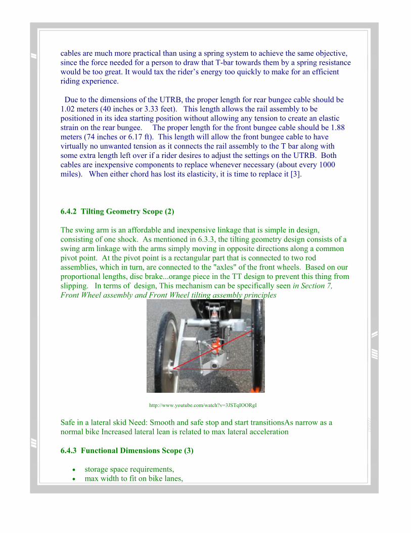
6.4.2 Tilting Geometry Scope (2)
The swing arm is an affordable and inexpensive linkage that is simple in design, consisting of one shock. As mentioned in 6.3.3, the tilting geometry design consists of a swing arm linkage with the arms simply moving in opposite directions along a common pivot point. At the pivot point is a rectangular part that is connected to two rod assemblies, which in turn, are connected to the "axles" of the front wheels. Based on our proportional lengths, disc brake...orange piece in the TT design to prevent this thing from slipping. In terms of design, This mechanism can be specifically seen in Section 7, Front Wheel assembly and Front Wheel tilting assembly principles
http://www.youtube.com/watch?v=3JSTqIOORgI Safe in a lateral skid Need: Smooth and safe stop and start transitionsAs narrow as a normal bike Increased lateral lean is related to max lateral acceleration
6.4.3 Functional Dimensions Scope (3)
• storage space requirements, • max width to fit on bike lanes,

• min height for visibility,
Overall dimensions can be seen in section 7, Subsystems, their properties and their sources
6.4.4 Exercise Scope
The UTRB serves as an excellent exercise machine engaging all muscle groups in order to serve as both a mode of transport and a means of exercise. The simple act of a human powering the vehicle utilizes a full range of muscle groups. In contrast to biking, the three phases of rowing incorporate the legs, abdomen and arms. By fine-tuning the range of motion and geometry of the rowing element by adjusting the settings on a UTRB (if needed to by modifying the design even further), it is possible to provide the optimal workout in transit.
6.4.5 Safety Scope (4)
Visible to all motorists Safe rider roadway visibility Both of these design goals are related to signaling and vehicle height. A signaling beacon can be mounted behind the seat of the vehicle in order to alert motorists of the vehicle's presence. With sufficient technical expertise and funding it may be possible to deploy a small camera on the front and back of the signaling beacon in order to give the rider improved visibility among cars.
6.4.6 Cost Scope (5)
Price under $1000 Lean angle minimum calculation minimum rear wheel width Minimum rider head height --> sizing rules for the seat overall sizing function and max, min ranges for length, width, height, etc. Max cable sizing based on different sized riders