design of support structures for offshore wind turbines .... seidel: design of support structures...
TRANSCRIPT
M. Seidel: Design of support structures for offshore wind turbines - Interfaces between project owner, turbine manufacturer, authorities and designer Published in: Stahlbau 79 (2010), Vol. 9
Page 1 of 13
Design of support structures for offshore wind turbines – Interfaces between project owner, turbine manufacturer, authorities and designer
Entwurf von Tragstrukturen für Offshore-WEA – Schnittstellen zwischen Projekteignern, WEA-Herstellern, Behörden und Tragwerksplanern
M. Seidel REpower Systems AG Franz-Lenz-Str. 1, 49084 Osnabrück Mail: [email protected] Internet: http://www.repower.de
Zusammenfassung Der Entwurf von Tragstrukturen für Offshore-Windenergieanlagen ist in technischer und logistischer Hinsicht eine anspruchsvolle Aufgabe. In diesem Prozess gibt es viele Betei-ligte, die zahllose Schnittstelle technischer und kommerzieller Art haben. Zur effizienten Behandlung dieser Schnittstellen sind zum Teil spezielle technische Vorgehensweisen hilfreich, die in dieser Veröffentlichung dargestellt werden. Der Erfolg eines Projektes ins-gesamt hängt maßgeblich von der erfolgreichen Abwicklung der Schnittstellen ab. Summary Design of support structures for offshore wind turbines is a challenging subject both tech-nically and logistically. Many stakeholders are involved in this process, which have many technical and commercial interfaces. Managing these interfaces can involved special tech-nical approaches and procedures, some of which are discussed in this paper. It is of great benefit to the project if these interfaces are managed well.
1. Introduction Offshore wind turbine installations are challenging objects for engineers of multiple disci-plines, project owners and authorities. As support structures (comprising tower, substruc-ture and foundations) are specific to every project, organizing interfaces between the vari-ous parties is important. This paper aims to provide some insight how these interfaces can be managed efficiently if all parties are willing to assume the responsibilities which are best taken care of by them. This is unfortunately not always the case, as parties try to miti-gate risks to other parties. 2. Project certification and BSH approval process
2.1. General remarks
An overview of the certification process is given in Fig. 1, which is taken from the forthcom-ing internal standard IEC 61400-22 [5]. This paper does not include a detailed discussion about project certification; this can be found in numerous publications, mainly from the cer-tification bodies.

M. Seidel: Design of support structures for offshore wind turbines - Interfaces between project owner, turbine manufacturer, authorities and designer Published in: Stahlbau 79 (2010), Vol. 9
Page 2 of 13
Fig. 1: Modules in Project Certification (from IEC 61400-22 [5])
Abbildung 1: Module der Projekt-Zertifizierung (aus IEC 61400-22 [5]) Some form of certification is customary for every project, although extent of certification varies. So far, the certification process and (if required) review by other authorities like BSH in Germany are rarely organized in an efficient way. This is mainly due to lack of ex-perience from the relevant players and hence non-sufficient knowledge about optimal or-ganization for this process.

M. Seidel: Design of support structures for offshore wind turbines - Interfaces between project owner, turbine manufacturer, authorities and designer Published in: Stahlbau 79 (2010), Vol. 9
Page 3 of 13
2.2. Documentation requirements for the "Design Basis" and "Design Brief"
The following definitions follow Norsok standard N-004 (Design of steel structures, Rev. 2). They are partly adopted to suit the specific requirements for offshore wind turbine installa-tions, but still they can be regarded as proven principles from the Oil&Gas sector. Hence, it is deemed sensible to adopt procedures which have proven to work in this area. Generally, adequate planning shall be undertaken in the initial stages of the design proc-ess in order to obtain a workable and economic structural solution to perform the desired function. As an integral part of this planning, documentation shall be produced identifying design criteria and describing procedures to be adopted in the structural design of the support structure for the wind turbines. Design documentation (see below) shall, as far as practicable, be concise, non-voluminous, and should include all relevant information for all phases of the lifetime of the unit. 2.2.1. Design Basis incl. site conditions
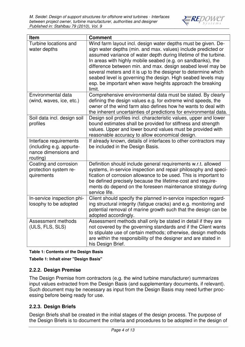
The "Design Basis" is prepared at the beginning of the design process. It is one of the most important documents in the entire process and its value and relevance should be recognized by project owners! The Design Basis is a catalogue of requirements set forth by the Owner. It contains spe-cific design requirements for the planned offshore wind farm. That implies that quantities which have inherent uncertainty (e.g. predicted wind speeds) are presented as unambigu-ous design values, which also reflect the Owner's desired level of safety. It is important that the Design Basis achieves a proper balance between defining the input which can only be given by the owner and leaving room to take advantage of the designer's experi-ence by not being too specific e.g. about design methods. The Design Basis has to be cer-tified by the project certification body. Items to be included in the Design Basis document typically are as stated in Table 1. Item Comment Applicable regulations, codes and standards (including revisions and dates)
Standards stated in the Design Basis reflect specific Owner's requirements; the list of standards shall therefore not be a comprehensive collection of standards available around the world – it should be as brief as possible and unambiguous. The hierarchy of codes is an important part in this respect. The owner must define which standards he wants to have pri-marily fulfilled and which can be used additionally if the govern-ing standard does not contain sufficient guidance. It should be noted that for Germany, DIN standards must be used as gov-erning standards.
General project descrip-tion, main dimensions (interface level, hub height, etc.)
Interface levels (level for mechanical connection, e.g. L-flange) shall be clearly defined to set-up mechanical models and to allow contractors to precisely define their scope of work (e.g. tower length or total substructure height).
M. Seidel: Design of support structures for offshore wind turbines - Interfaces between project owner, turbine manufacturer, authorities and designer Published in: Stahlbau 79 (2010), Vol. 9
Page 4 of 13
Item Comment Turbine locations and water depths
Wind farm layout incl. design water depths must be given. De-sign water depths (min. and max. values) include predicted or assumed variance of water depth during lifetime of the turbine. In areas with highly mobile seabed (e.g. on sandbanks), the difference between min. and max. design seabed level may be several meters and it is up to the designer to determine which seabed level is governing the design. High seabed levels may esp. be important when wave heights approach the breaking limit.
Environmental data (wind, waves, ice, etc.)
Comprehensive environmental data must be stated. By clearly defining the design values e.g. for extreme wind speeds, the owner of the wind farm also defines how he wants to deal with the inherent uncertainties of predictions for environmental data.
Soil data incl. design soil profiles
Design soil profiles incl. characteristic values, upper and lower bound estimates shall be provided for stiffness and strength values. Upper and lower bound values must be provided with reasonable accuracy to allow economical design.
Interface requirements (including e.g. appurte-nance dimensions and routing)
If already known, details of interfaces to other contractors may be included in the Design Basis.
Coating and corrosion protection system re-quirements
Definition should include general requirements w.r.t. allowed systems, in-service inspection and repair philosophy and speci-fication of corrosion allowance to be used. This is important to be defined precisely because the lifetime-cost and require-ments do depend on the foreseen maintenance strategy during service life.
In-service inspection phi-losophy to be adopted
Client should specify the planned in-service inspection regard-ing structural integrity (fatigue cracks) and e.g. monitoring and potential removal of marine growth such that the design can be adopted accordingly.
Assessment methods (ULS, FLS, SLS)
Assessment methods shall only be stated in detail if they are not covered by the governing standards and if the Client wants to stipulate use of certain methods; otherwise, design methods are within the responsibility of the designer and are stated in his Design Brief.
Table 1: Contents of the Design Basis
Tabelle 1: Inhalt einer "Design Basis" 2.2.2. Design Premise
The Design Premise from contractors (e.g. the wind turbine manufacturer) summarizes input values extracted from the Design Basis (and supplementary documents, if relevant). Such document may be necessary as input from the Design Basis may need further proc-essing before being ready for use. 2.2.3. Design Briefs
Design Briefs shall be created in the initial stages of the design process. The purpose of the Design Briefs is to document the criteria and procedures to be adopted in the design of

M. Seidel: Design of support structures for offshore wind turbines - Interfaces between project owner, turbine manufacturer, authorities and designer Published in: Stahlbau 79 (2010), Vol. 9
Page 5 of 13
the support structures. The Design Briefs are prepared by the parties being responsible for the component in question. The Design Briefs shall, as far as practicable, be concise, non-voluminous, and, should include all relevant limiting design criteria for the relevant design phase. Design Briefs re-quired are e.g. as stated in Table 2.
Design Brief Responsibility Design Brief for tower design evaluation Wind Turbine Manufacturer
Design Brief for integrated load calculations Wind Turbine Manufacturer Design Brief(s) for substructure design evaluation Substructure Designer
Table 2: Overview of Design Briefs in a project
Tabelle 2: Überblick über "Design Brief"-Dokumente in einem Projekt Structural design briefs typically cover the following topics:
• ULS assessment (Extreme Event)
• FLS assessment (Fatigue)
• SLS assessment (Serviceability)
• Material selection
• Modal analysis
• Grouted Connections (if relevant)
• Corrosion & Cathodic Protection
• Scour Protection Design (if relevant)
• Ship Impact
• Geotechnical assessment
• Secondary Steel Design
• FE Analyses of Details
2.3. BSH approval process (Germany only)
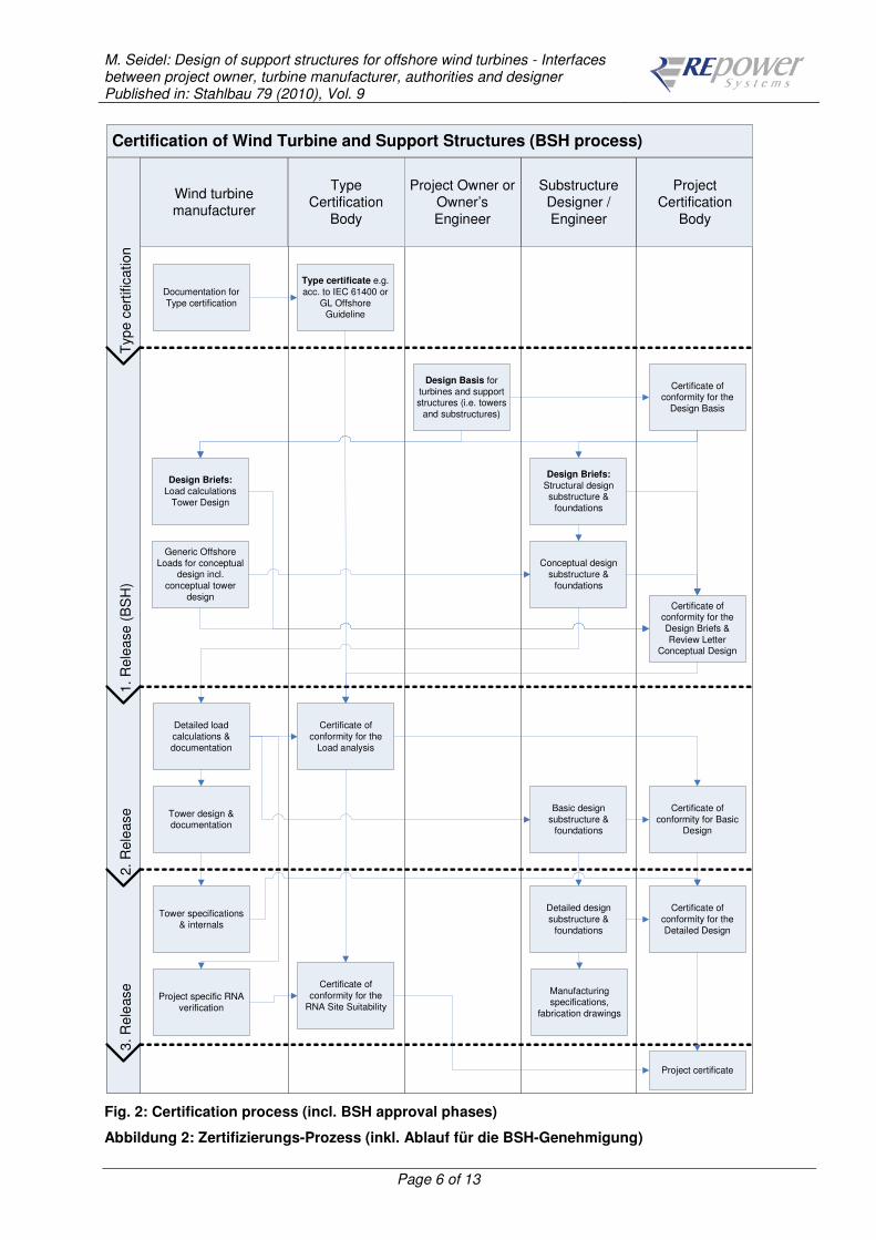
In Germany, approval for offshore wind farms is granted by BSH ("Bundesamt für See-schifffahrt und Hydrographie" = Federal Maritime and Hydrographic Agency). The approval process for the design phase is described in [6]. A specific flow-chart is shown in Fig. 2. This flow-chart does also show the responsibilities of all parties participat-ing in the design process. The BSH approval process is specific to German projects, but the general process is also valid for projects outside of Germany. The BSH approval process is not yet an established procedure, hence it is expected that it will further develop with the experience gained from the first projects. The description here is based on the experience of the author and his interpretation of the BSH standard.
M. Seidel: Design of support structures for offshore wind turbines - Interfaces between project owner, turbine manufacturer, authorities and designer Published in: Stahlbau 79 (2010), Vol. 9
Page 6 of 13
Certification of Wind Turbine and Support Structures (BSH process)T
yp
e c
ert
ific
ation
1. R
ele
ase (
BS
H)
2. R
ele
ase
3. R
ele
ase
Type Certification
Body
Wind turbine manufacturer
Substructure Designer /
Engineer
Project Owner or Owner’s
Engineer
Project Certification
Body
Design Basis for
turbines and support structures (i.e. towers
and substructures)
Type certificate e.g.
acc. to IEC 61400 or
GL Offshore Guideline
Documentation for
Type certification
Design Briefs:Load calculations
Tower Design
Generic Offshore
Loads for conceptual design incl.
conceptual tower
design
Design Briefs:Structural design substructure &
foundations
Conceptual design
substructure &
foundations
Certificate of conformity for the
Design Basis
Certificate of conformity for the
Design Briefs &
Review Letter Conceptual Design
Detailed load
calculations &
documentation
Tower design & documentation
Detailed design
substructure &
foundations
Certificate of
conformity for the
Load analysis
Tower specifications
& internals
Manufacturing specifications,
fabrication drawings
Project specific RNA
verification
Certificate of
conformity for the
Detailed Design
Certificate of
conformity for the
RNA Site Suitability
Project certificate
Basic design
substructure & foundations
Certificate of
conformity for Basic Design
Fig. 2: Certification process (incl. BSH approval phases)
Abbildung 2: Zertifizierungs-Prozess (inkl. Ablauf für die BSH-Genehmigung)
M. Seidel: Design of support structures for offshore wind turbines - Interfaces between project owner, turbine manufacturer, authorities and designer Published in: Stahlbau 79 (2010), Vol. 9
Page 7 of 13
For certification acc. to BSH standard it is important to know that BSH requires that techni-cal rules acknowledged by German authorities are applied. A list of accepted standards ("Bauregelliste") can be found at "Deutsches Institut für Bautechnik" (DIBt): http://www.dibt.de/en/News_Technische_Baubestimmungen.html Use of other standards (e.g. DNV, API, etc.) is only accepted by BSH if the standards given in above list do not contain applicable rules. Such deviations must be applied for and justification for such an approach must be elaborated in detail. If a design detail is not covered by above list, then the second-best source for potentially acceptable standards to be used are published DIN standards. These can be found at www.beuth.de. It can e.g. be noted that ISO 19902 has been published as DIN EN ISO 19902 [7]. The following shall be considered when preparing documentation for the different stages. 1st Release:
• BSH requires that design procedures are already stated in detail for the 1st Release. That implies that the Design Briefs must be supplied at this stage! This may be diffi-cult to achieve in reality, because contractors are not yet known. This is something which must be agreed upon with BSH.
• The degree of refinement and accuracy of the conceptual design is low for the 1st re-lease. It is important though, that possible substructures and the corresponding over-all structural layout (platform height, hub height, etc.) are given. It is sufficient at this stage that masses, structural dimensions, etc. are estimated within an accuracy of about ±20%, but generally values should rather be on the conservative side.
• Upper bound estimates of structural dimensions shall be provided; special care should be paid to all aspects related to the Environmental Impact Assessment (EIA), e.g.: - Diameter of Gravity Base Structures (GBS), extent of soil excavation and seabed preparation and sediment management concept (e.g. reuse as ballast) - Scour protection concept and dimensions - Pile lengths and dimension (important for driving noise)
2nd Release:
• 2nd release must be achieved at least one year before installation begins. Therefore, the certified Design Basis should be finished at least 24 months before scheduled start of installation in order to allow sufficient time to prepare documentation.
• The load calculations at this stage will be site-specific, taking the actually planned substructures into account. Therefore, the resulting Basic Design will be very close to the final Detailed Design, which is documented for the 3rd release.
3. Engineering process Engineering and certification are parallel processes. This section describes the (typical) engineering process which is required for certification of RNA (rotor-nacelle-assembly, i.e. turbine nacelle, hub and blades), tower and substructure.

M. Seidel: Design of support structures for offshore wind turbines - Interfaces between project owner, turbine manufacturer, authorities and designer Published in: Stahlbau 79 (2010), Vol. 9
Page 8 of 13
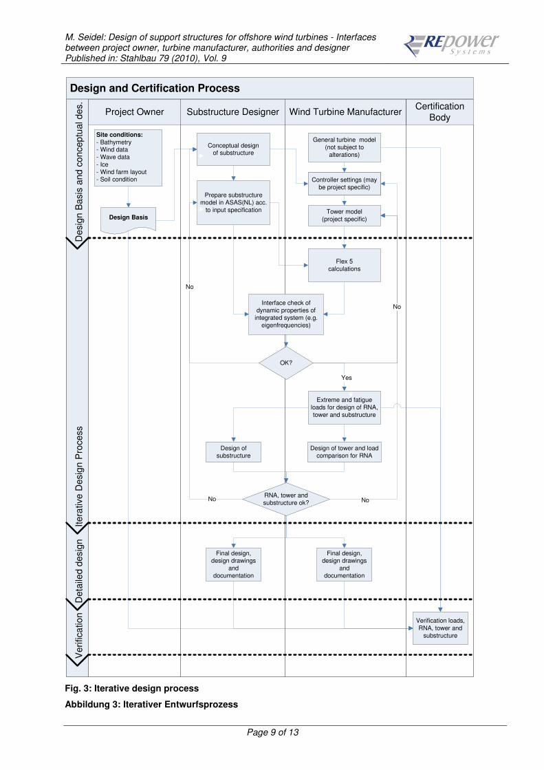
The design process for the support structure is typically iterative because the structural stiffness has an impact on the loads. An overview for this iterative procedure is provided in Fig. 3. For this figure it is assumed that the wind turbine simulation is carried out with Flex 5 and the substructure design with ANSYS ASAS(NL). During this process the components are checked as an integrated system. Adverse condi-tions (e.g. resonance problems leading to increase in loads due to unfavorable eigenfre-quencies or excessive dynamic excitation from wave loading due to insufficient stiffness of the substructure) will be detected and appropriate changes to the system can then be made ("interface check" in Fig. 3). Changes may be necessary esp. to the stiffness of the support structure (tower and/or substructure) or to controller settings of the turbine (where applicable). The number of iterations required depends on site conditions and type of substructure. Generally, the following can be assumed:
• Jackets are not sensitive to wave loading and loads are only moderately affected by changes in structural stiffness. Therefore, just one iteration is often sufficient in this case. The lower part of the jacket and the pile design itself may be an exception to this rule as they are more sensitive to soil properties, esp. lateral stiffness assump-tions.
• Monopiles and some Gravity Base Structures (GBS) are much more sensitive to wave loading and also soil stiffness. In this case, two or more iterations are typically required.
M. Seidel: Design of support structures for offshore wind turbines - Interfaces between project owner, turbine manufacturer, authorities and designer Published in: Stahlbau 79 (2010), Vol. 9
Page 9 of 13
Design and Certification ProcessD
esig
n B
asis
and c
on
ceptu
al des.
Itera
tive D
esig
n P
rocess
Deta
iled d
esig
nV
erifica
tion
No
Certification
BodyWind Turbine ManufacturerSubstructure DesignerProject Owner
Site conditions:- Bathymetry- Wind data
- Wave data
- Ice
- Wind farm layout- Soil condition
Design Basis
Design of
substructure
RNA, tower and
substructure ok?
Conceptual design of substructure
Prepare substructure
model in ASAS(NL) acc.
to input specification
Flex 5
calculations
Design of tower and load
comparison for RNA
General turbine model
(not subject to
alterations)
Verification loads,
RNA, tower and
substructure
Final design, design drawings
and
documentation
Final design, design drawings
and
documentation
Controller settings (may
be project specific)
Tower model
(project specific)
Controller settings (may
be project specific)
Interface check of
dynamic properties of integrated system (e.g.
eigenfrequencies)
Extreme and fatigue
loads for design of RNA,
tower and substructure
OK?
Yes
No
No
No
Fig. 3: Iterative design process
Abbildung 3: Iterativer Entwurfsprozess

M. Seidel: Design of support structures for offshore wind turbines - Interfaces between project owner, turbine manufacturer, authorities and designer Published in: Stahlbau 79 (2010), Vol. 9
Page 10 of 13
4. Integrated load analysis Integrated load analysis is an important part of the design process. Since 2008, the new standard IEC 61400-3 exists [4] which is regarded as the most up-to-date reference for offshore load calculations. Nevertheless, it is recognized by experts and also the IEC maintenance group that this area is still in rapid development and therefore review of first practical experience using the standard will be used to further develop its contents. During this process, it is required that a model of the substructure, which is typically not under the responsibility of the wind turbine manufacturer, is used for the load calculations. Interface problems are minimized in this case if the model can be prepared by the sub-structure designer himself. This can e.g. be done by using the sequential coupling method as described in [1]. REpower has developed calculation procedures which can make effec-tive use of externally prepared ASAS(NL) models (which must be prepared in a precisely specified way). The sequential coupling has been found to be conservative compared to more accurate models, see [2]. A visualization of such an integrated model is shown in Fig. 4.
Fig. 4: Integrated model for load simulations
Abbildung 4: Integriertes Modell für Lastsimulationen Using such an approach, the design process can be organized as follows:
1) Structural models are prepared by the substructure designer in accordance with the input specification. The substructure designer can hence model the substructure with the required accuracy under his own responsibility.

M. Seidel: Design of support structures for offshore wind turbines - Interfaces between project owner, turbine manufacturer, authorities and designer Published in: Stahlbau 79 (2010), Vol. 9
Page 11 of 13
2) Said models are used in a sequential analysis by the wind turbine manufacturer, the global dynamical behaviour and impact of wave loads are then adequately covered.
3) Loads and/or displacement time series at the tower-substructure interface are trans-ferred to the substructure designer for further processing, i.e. ULS and FLS design. This is a big advantage for the design because model consistency is ensured throughout the whole process.
This approach has been used successfully by REpower in several projects. The same ap-proach can also be used with other codes, e.g. Poseidon (developed by Cord Böker at the Leibniz University of Hannover [3]) if the procedures are adapted to suit the input formats of such other codes. The responsibilities should ideally be split as follows:
• Responsibility relevant for the hydrodynamic loading should rest with the substruc-ture designer. He should provide all relevant input to the wind turbine manufacturer (e.g. regarding hydrodynamic coefficients or special items like time series of break-ing wave forces). This goes along with the responsibility for the structural model it-self.
• Responsibility for integrating the wave loads in the integrated load analysis rests with the turbine manufacturer, because he is essentially the only party capable to assume this responsibility.
During the integrated load analysis, it is important to understand the system's behaviour and to adopt the design approach accordingly. It is e.g. crucial to understand whether wave excitation is a significant issue for (global) fatigue loads of the structure. This is typi-cally the case for Monopiles. In this case, great care must be exercised to take account of the following:
a) Dynamic excitation due to wave loading is strongly influenced by the first natural frequency and the mode shape in the wave loaded zone. Accurate determination of soil stiffness and soil-pile-interaction is therefore important.
b) Damping is small in cross-wind direction as no (or only small) aerodynamic damp-ing exists. This means that esp. wind-wave-misalignment can be critical. It is there-fore crucial to accurately define the overall structural damping (which is also in-fluenced by soil damping) and wind-wave-directionality.
For jackets, on the other hand, wave loading is much less important. The above mentioned items can therefore be treated in a simplified manner. Only in the lower part of the jacket, member forces are influenced by pile stiffness and care when modelling soil-pile-interaction is required.
5. Installation tolerances Tolerances are another important interface between various parties. Some cases with im-portance also for the design works are:
1) Substructure inclination: Permanent inclination of the substructure, resulting from installation tolerance and settlement during operation, causes additional loading due to the resulting eccentricities of nacelle, tower, etc. Typically, an allowable total

M. Seidel: Design of support structures for offshore wind turbines - Interfaces between project owner, turbine manufacturer, authorities and designer Published in: Stahlbau 79 (2010), Vol. 9
Page 12 of 13
inclination of 0.5° is taken into account for the design which must be properly en-sured during installation and potentially be monitored during service life.
2) Positional tolerances of bolts: Esp. for gravity based structures, where anchor cages are often used to connect substructure and tower, the positional tolerances of the bolts is important (Fig. 5), because many bolts have to fit into many holes when the tower is installed onto the substructure. This can have an impact at the design stage, because larger tolerances can be allowed if the construction is adapted ac-cordingly (e.g. by using larger bolt holes with special washers in the tower bottom flange).
3) Tolerances for L-flanges: If an L-flange (inside of the tower) is used to connect tower and substructure (as e.g. done when jackets are used), then flange flatness and out-of-roundness are crucial tolerances to ensure reliability of the connection as well as ability to install the towers (which could be endangered when the out-of-roundness tolerance is exceeded).
Fig. 5: Mechanical interface for a gravity base structure (GBS)
Abbildung 5: Mechanische Schnittstelle für eine Schwergewichtsgründung

M. Seidel: Design of support structures for offshore wind turbines - Interfaces between project owner, turbine manufacturer, authorities and designer Published in: Stahlbau 79 (2010), Vol. 9
Page 13 of 13
6. Summary Interfaces between all parties in an offshore wind project are numerous during design, cer-tification and construction. In this paper, some items regarding esp. regarding substructure design have been discussed, but there are countless other interfaces in other disciplines (e.g. cabling and windfarm management) as well. Proper management of these interfaces, esp. clearly identifying and accepting responsibilities is of big importance for the success of a project.
7. References [1] Seidel, M. et al.: Integrated analysis of wind and wave loading for complex support
structures of Offshore Wind Turbines. Conference Proceedings Offshore Wind 2005, Copenhagen 2005.
[2] Seidel, M. et al.: Validation of Offshore load simulations using measurement data from the DOWNVInD project. Conference Proceedings Offshore Wind 2009, Stock-holm 2009.
[3] Böker, C.: Load simulation and local dynamics of support structures for offshore wind turbines. Institute for Steel Construction, Leibniz University of Hannover, 2009.
[4] IEC 61400-3: Wind turbines – Part 3: Design requirements for offshore wind tur-bines, 1st Edition 2009
[5] IEC 61400-22 Ed.1: Wind turbines - Part 22: Conformity Testing and Certification (FDIS); Document 88/365/FDIS, 2010-02-26
[6] BSH: Standard "Design of Offshore Wind Turbines", BSH No. 7005, 20 December 2007 ("BSH Standard Design"), available for download at: http://www.bsh.de/en/Products/Books/Standard/index.jsp (English)
[7] DIN EN ISO 19902:2008-07: Petroleum and natural gas industries - Fixed steel off-shore structures (ISO 19902:2007); English version EN ISO 19902:2007