design of steel structures dr. damodar maity department of...
TRANSCRIPT
Design of Steel Structures
Dr. Damodar Maity
Department of Civil Engineering
Indian Institute of Technology, Guwahati
Module - 6
Flexural Members
Lecture - 7
Design of a Built-Up Beams
Hello, today we will be solving an workout example on design of built-up beam. In last 2
lectures, whatever we have discussed about different aspects of built-up beam those
things we will apply through 1 example. When we will go through this example workout
example then we will see how to apply the codal provisions and other things step by step.
As we know that built-up section are made only when the load is high or the depth is
restricted from architectural or from some other point of view or the span of the beam is
very high. And to restrict the depletion excessive depletion we may have to go for built-
up sections right. So, today first I will go through 1 example I do not know how much I
will be able to finish because this is a long example. And you must give your
concentration to each steps otherwise it will be difficult to understand the entire process
thoroughly. I will try to go as slow as possible, but again as we have limited time means
only 1 hour we can spend for a particular lecture. So, I will try to finish the entire
example in this lecture itself.
(Refer Slide Time: 02:41)
We will just see how much we can do. Now, built-up section means generally we feel in
case of beam as like this say I section. And then plate section most commonly we use
right say it may be symmetrical it may be unsymmetrical. Then if we use more than 1
plate generally either we use same width of the plate or maybe larger than that. We can
use like this. But never we use say like this then this. What is the beneficial of this
because when we are using the higher section higher width of or higher area of plate at
the outermost the moment of inertia will become high.
But, in this case moment of inertia will become will become with same arrangement
suppose if we make here the moment of inertia will become less. And our motto is to
make the arrangement in such a way that the moment of inertia of the built-up section is
become as high as possible with the same material.
(Refer Slide Time: 03:59)
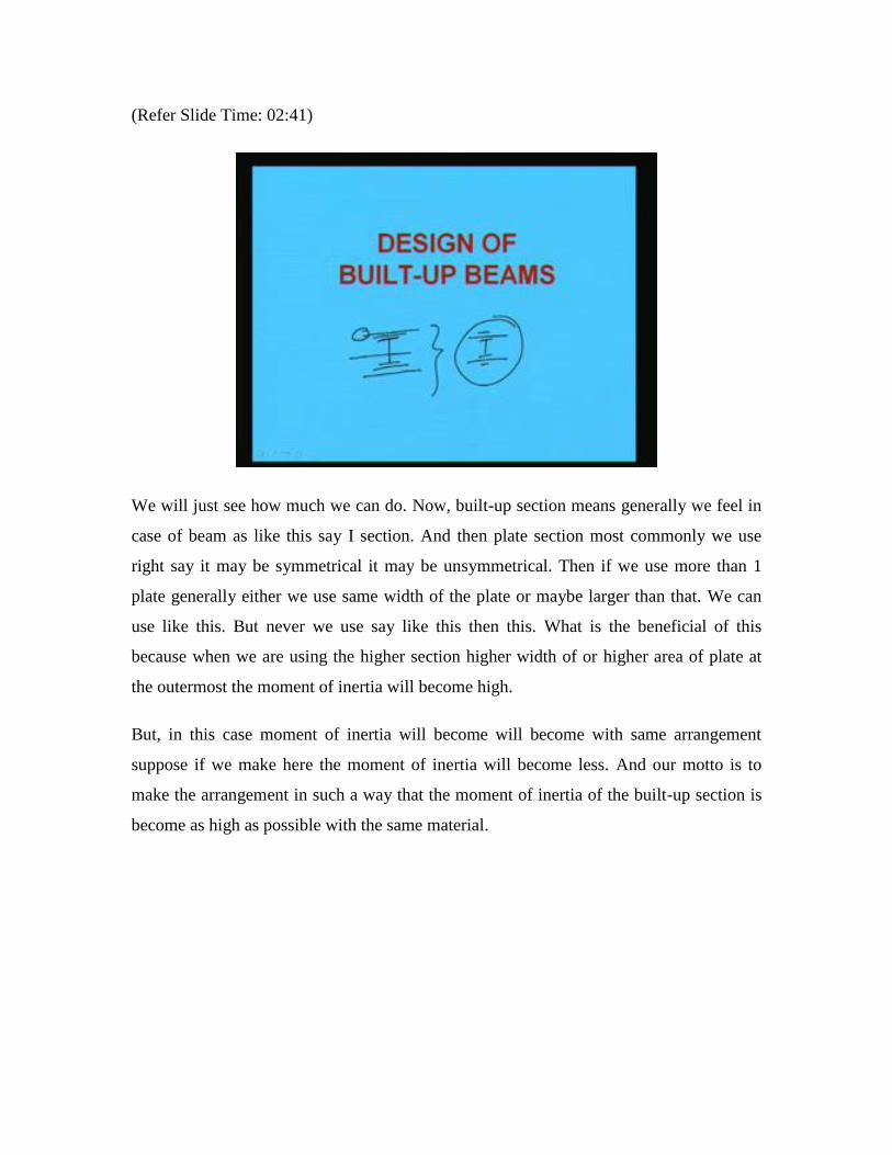
This example is like this that a beam of 7 meter effective length carrying a uniform load
of 50 kilo Newton per meter including of self weight over the entire span right. The
compression flange of the beam is laterally supported throughout. If the overall depth of
the beam is restricted to 3 100 mm design the beam with a suitable section. Assume for
steel fy has 2 50 millimeter right.
So, what we have seen that a beam that is 7 meter effective length is carrying a uniform
load of 50 kilo Newton per meter right which include self weight also. The compression
flange is laterally supported. So, sigma bc will be sigma bt will be point 6 six fy. And fy
is 2 fifty. So, this will become 1 65 MPa. So, sigma ac and sigma bt is known now. And
now other thing is that. So, design the beam which is suitable to this here it is not given.
Assume that it is a simply supported beam simply supported beam. So, let us assume
simply supported beam. And this also hum it was by mistake 300 it was say 350
restricted to 350 mm the beam depth is restricted to 350 mm right. So, D should not be
greater than 350 mm over all. So, these are things, which has been given right. So, now
what we will do we will go for the solution.
So, you just write down that a simply supported beam which is carrying 50 kilo Newton
50 kilo Newton per meter load which includes the self weight also the span length is 7
mm 7 meter. And the maximum depth is limited to 350 and this is simply supported right.
(Refer Slide Time: 07:09)
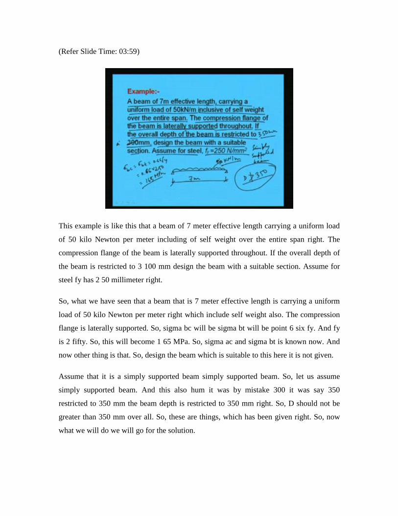
So, with these conditions let us make it. So, now we will solve the problem whichever
was given. In first step what we will do we will find out the load on the beam and it was
told that load is 50 kilo Newton per meter right 50 kilo Newton per meter which includes
self weight also. Now, in next step we will find out the maximum moment as for the case
of the simply supported beam with ideal load. We know that maximum bending moment
will be wl square by 8. So, w is 50 and l is 7. So, wl square by 8 is becoming 3 0 6 point
2 5 kilo newton meter right.
Then maximum shear force we are going to get as wl by 2 this is 1 75 kilo Newton
maximum shear force as we know it will occur at the support for this particular case and
this will be wl by 2. So, if we calculate this value we will get V is equal to wl by 2 is
equal to 50 into 7 by 2 is equal to 1 75 kilo Newton right. Now, we will find out the
section modulus in step 3 we will find out section modulus on the basis of developed
moment and the allowable shear allowable bending stress.
Now, as the beam is laterally supported throughout its length. So, we can write sigma bt
is equal to sigma bc that will become 165 right. Because, this is 0.66 fy and fy is 250. So,
after multiplication we will get 165 MPa right. So, we can find out Z is equal to M by
sigma bc. Now, M is 306.25 kilo Newton. So, this we are making Newton with
multiplying 10 to power 6. By sigma bc or sigma bt that is supposed to be 165. But, we
are making 155 thinking that as we are going to use plate and for that we need to provide
some rivet connection.
So, the net area of the flange will be less that is why to accommodate that we are slightly
reducing the permissible stress. That means, from 165 to we are making 155, so that we
will in higher side in terms of section modulus. So, that the section whatever we will be
choosing will be little higher side. Because later when we will be reducing the area
because of the presence of rivet hole then the stress will become high. So, to adopt that 1
at the beginning itself we are choosing little less stress so that the section modulus
become little high.
(Refer Slide Time: 10:15)
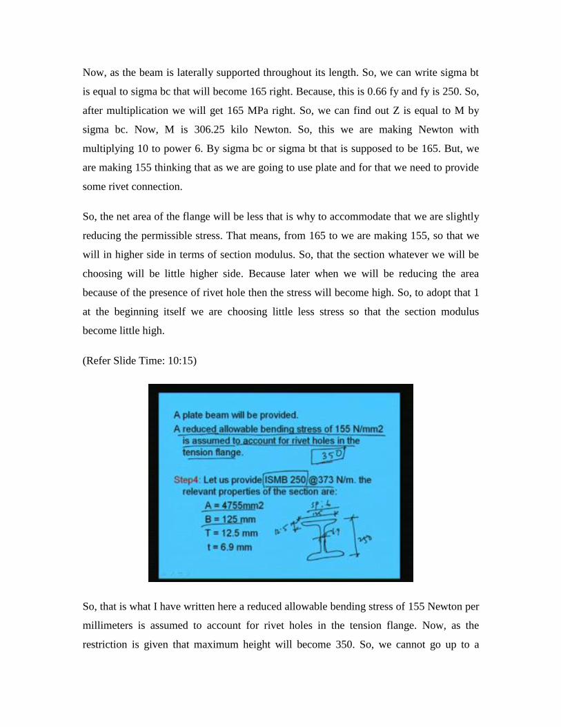
So, that is what I have written here a reduced allowable bending stress of 155 Newton per
millimeters is assumed to account for rivet holes in the tension flange. Now, as the
restriction is given that maximum height will become 350. So, we cannot go up to a

certain means whatever we want the section we cannot go beyond that right. So,
considering this let us use say ISMB 2 50 at 3 7 3 Newton per meter. And if we are going
to use ISMB 250 then what are the properties, which is given in SP 6 in tabular form it is
given like.
Area of ISMB 250 is given 4755 millimeter square. Width is given 1 25 if I see the
diagram we will see it is like this because this will be required case to case. So, let us
make the diagram here. So, this is 250 and b the width of flange is 125 right. And
thickness of flange T is equal to 12.5 and thickness of web is equal to 6.9 right. So, these
are the things we can find out from the code.
(Refer Slide Time: 11:51)
Along with that Ixx the moment of inertia about the major axis and similarly Zxx which
is given in the code. That is Ixx is 51316000 millimeter to the power 4.And Zxx will be
410500 millimeter cube. H 2 will be 27.95 millimeter. Gauge distance g will be 65
millimeter. So, these are the things which we will be required in different places for the
calculation of the design of the built-up section. So, now what will be Zp as we know
required minus the available. So, Z required was this 1 this we found here Z required this
is the Z required 1975800 millimeter cube. And Z available is this one. So, 1975800
minus available is 410500.
So, Zp means section modulus has to provide this much with the additional plate. So,
1565300 millimeter cube has to be provided. So, area of the plate has to become Zp by D
which will be becoming 1565300 by 2 50. And if we take the ratio of this we will get the
value of Ap area of plate this will become 6261.2 millimeter square. So, area of plate will
be required 6261.2 millimeter square.
(Refer Slide Time: 13:49)
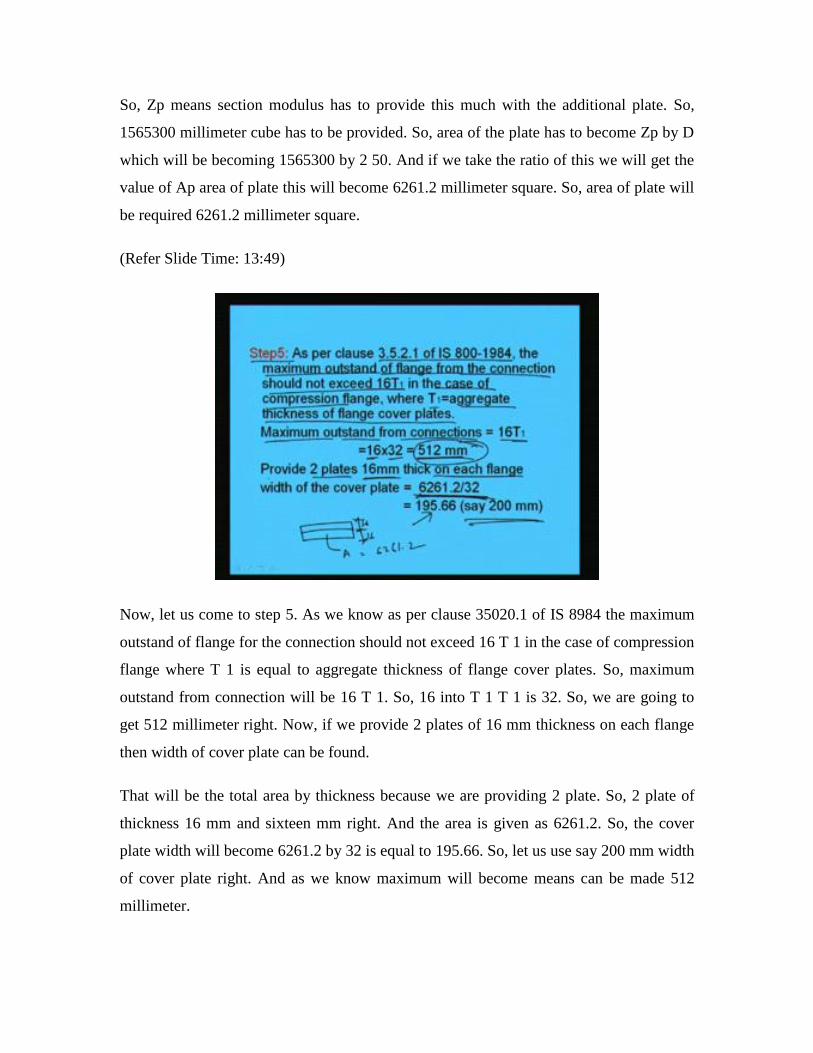
Now, let us come to step 5. As we know as per clause 35020.1 of IS 8984 the maximum
outstand of flange for the connection should not exceed 16 T 1 in the case of compression
flange where T 1 is equal to aggregate thickness of flange cover plates. So, maximum
outstand from connection will be 16 T 1. So, 16 into T 1 T 1 is 32. So, we are going to
get 512 millimeter right. Now, if we provide 2 plates of 16 mm thickness on each flange
then width of cover plate can be found.
That will be the total area by thickness because we are providing 2 plate. So, 2 plate of
thickness 16 mm and sixteen mm right. And the area is given as 6261.2. So, the cover
plate width will become 6261.2 by 32 is equal to 195.66. So, let us use say 200 mm width
of cover plate right. And as we know maximum will become means can be made 512
millimeter.
(Refer Slide Time: 15:30)
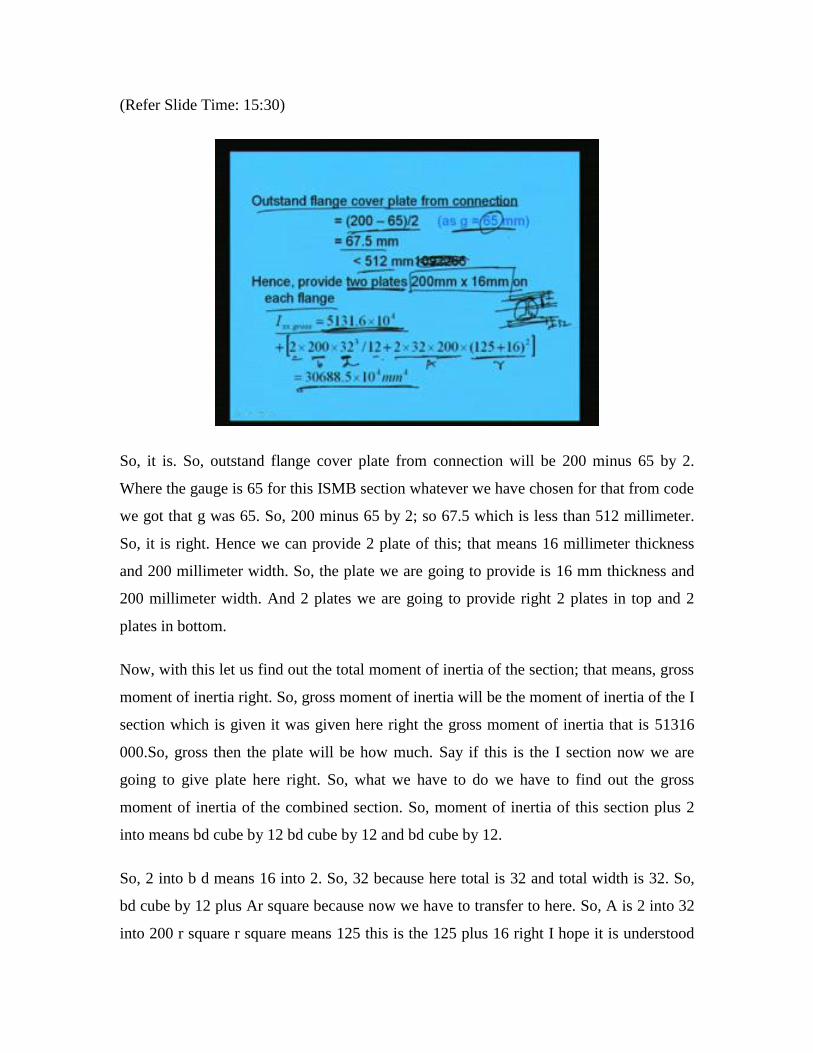
So, it is. So, outstand flange cover plate from connection will be 200 minus 65 by 2.
Where the gauge is 65 for this ISMB section whatever we have chosen for that from code
we got that g was 65. So, 200 minus 65 by 2; so 67.5 which is less than 512 millimeter.
So, it is right. Hence we can provide 2 plate of this; that means 16 millimeter thickness
and 200 millimeter width. So, the plate we are going to provide is 16 mm thickness and
200 millimeter width. And 2 plates we are going to provide right 2 plates in top and 2
plates in bottom.
Now, with this let us find out the total moment of inertia of the section; that means, gross
moment of inertia right. So, gross moment of inertia will be the moment of inertia of the I
section which is given it was given here right the gross moment of inertia that is 51316
000.So, gross then the plate will be how much. Say if this is the I section now we are
going to give plate here right. So, what we have to do we have to find out the gross
moment of inertia of the combined section. So, moment of inertia of this section plus 2
into means bd cube by 12 bd cube by 12 and bd cube by 12.
So, 2 into b d means 16 into 2. So, 32 because here total is 32 and total width is 32. So,
bd cube by 12 plus Ar square because now we have to transfer to here. So, A is 2 into 32
into 200 r square r square means 125 this is the 125 plus 16 right I hope it is understood

right. So, 5131.6 into 10 to the power 4 plus 2 into 200 into 32 cube by 12 plus 2 into 32
into 200 into 125 plus 16 square this is r this is A this is b this is d right. So, finally, the
gross moment of inertia about xx is 30688.5 into 10 to the power 4 millimeter to the
power 4. So, Ixx is 30688.5 into 10 to the power 4 millimeter to the power 4.
(Refer Slide Time: 18:45)
Now, we can find out sigma bc. So, sigma bc will be how much M by I into y at the
extreme fiber. So, M was calculated here earlier 306.25 that is maximum moment. And
gross moment of inertia is 30688.5 into 10 to the power 4. And I will become 125 plus 32
because at the extreme fiber we have to calculate if I see. So, this is 125 and this is 32
right. So, this 1. So, after calculating this we will get sigma bc cal is equal to 156.67
Newton per millimeter square which is less than 166 right. Because, this is the allowable
permissible stress in bending because of the beam flange is supported laterally right.
Now, we will go for step 6. Now, we will in step 6 what we will do we will check for
bending stress in tension bending stress in tension. It will be will have to check because
of the presence of the rivet because of the presence of the rivet the net area of the tension
flange will be going to reduce. And that is why the tensile stress will develop more
because of the hole. So, that we have check that whether it is exceeding or not. Now, let
us see now say let us connect the cover plates with the flange by twenty mm diameter
rivets. And the rivets are provided staggered in 2 rows.
So, if this is the I section sorry if say let me draw the I section right. Now, we are
providing some plate here right and we are having the rivet here right and 20 mm
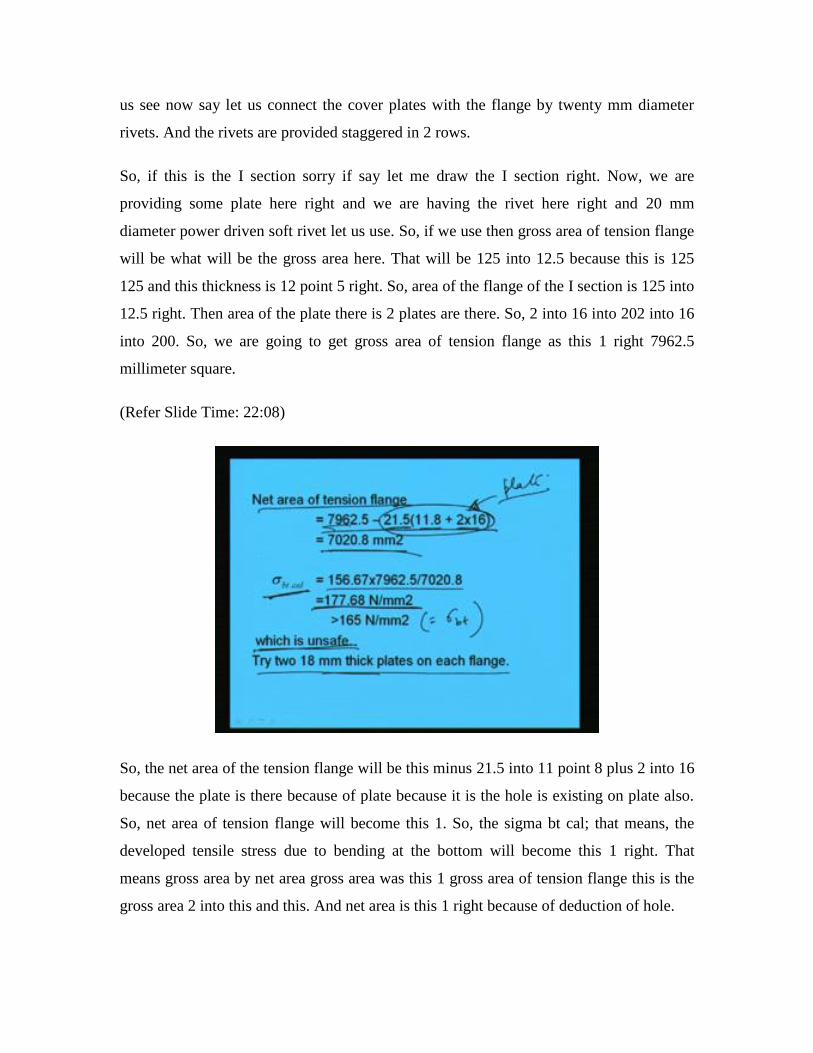
diameter power driven soft rivet let us use. So, if we use then gross area of tension flange
will be what will be the gross area here. That will be 125 into 12.5 because this is 125
125 and this thickness is 12 point 5 right. So, area of the flange of the I section is 125 into
12.5 right. Then area of the plate there is 2 plates are there. So, 2 into 16 into 202 into 16
into 200. So, we are going to get gross area of tension flange as this 1 right 7962.5
millimeter square.
(Refer Slide Time: 22:08)
So, the net area of the tension flange will be this minus 21.5 into 11 point 8 plus 2 into 16
because the plate is there because of plate because it is the hole is existing on plate also.
So, net area of tension flange will become this 1. So, the sigma bt cal; that means, the
developed tensile stress due to bending at the bottom will become this 1 right. That
means gross area by net area gross area was this 1 gross area of tension flange this is the
gross area 2 into this and this. And net area is this 1 right because of deduction of hole.
So, the area tensile stress is coming 177.68 Newton per millimeter square which is
greater than the sigma bt the allowable bending stress in tension. Allowable bending
stress in tension which is equal to point 66 fy and in this case it will be 165 Newton per
millimeter square right. So, sigma bt cal; that means, the calculated bending stress in
tension is coming higher than the allowable 1. So, we can say that this is unsafe.
That means if it is unsafe what we have to do we have to increase the plate thickness or
plate diameter plate width or something. So, now let us use some higher thickness of the
plate. Say let us try with 218 mm thickness plate on each flange right.
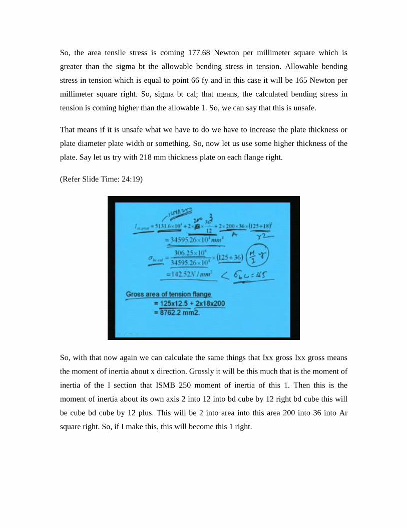
(Refer Slide Time: 24:19)
So, with that now again we can calculate the same things that Ixx gross Ixx gross means
the moment of inertia about x direction. Grossly it will be this much that is the moment of
inertia of the I section that ISMB 250 moment of inertia of this 1. Then this is the
moment of inertia about its own axis 2 into 12 into bd cube by 12 right bd cube this will
be cube bd cube by 12 plus. This will be 2 into area into this area 200 into 36 into Ar
square right. So, if I make this, this will become this 1 right.

(Refer Slide Time: 25:21)
So, if you see earlier the gross area we have calculated like this you see this plus 2 into
this plus this. This was 30688 into 10 to power 4. And here it is coming 34595 into 10 to
power 4. So, it is going to increase. So, what we are doing for gross area that a moment
of inertia of the section ISMB then moment of inertia about its own axis. That is 2 into b
sorry b will be 200 bd cube by 12 plus A this is Ar square, right.
So, after calculating we are getting 34595.26 into 10 to power 4 millimeter to the 4. So,
now we can find out sigma bc calculated the bending stress in compression. So, that is M
by I into y right. So, M is 306.25 into 10 to the 6. I is 3459.59 5.26 into 10 to the power 4.
And y is the distance from cg to the extreme fiber that is 125 plus 36 because 18
millimeter plate thickness of 2 plate. So, 36 plus 125 is the means half depth of the
section.
So, after calculating this we are going to get sigma bc calculated as 142.52 newton per
millimeter square which is less than allowable sigma bc that is 1 65. So, this is … Now,
similarly again we will find out the gross area of tension flange gross area of tension
flange will be simply 125 into 12.5. That is the flange of the section I section and this is
the plate 2 into 18 into 200. So, area will be 8762.2.
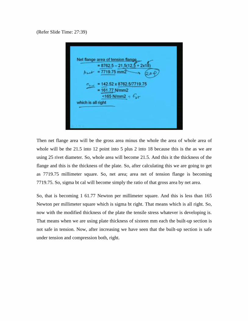
(Refer Slide Time: 27:39)
Then net flange area will be the gross area minus the whole the area of whole area of
whole will be the 21.5 into 12 point into 5 plus 2 into 18 because this is the as we are
using 25 rivet diameter. So, whole area will become 21.5. And this it the thickness of the
flange and this is the thickness of the plate. So, after calculating this we are going to get
as 7719.75 millimeter square. So, net area; area net of tension flange is becoming
7719.75. So, sigma bt cal will become simply the ratio of that gross area by net area.
So, that is becoming 1 61.77 Newton per millimeter square. And this is less than 165
Newton per millimeter square which is sigma bt right. That means which is all right. So,
now with the modified thickness of the plate the tensile stress whatever is developing is.
That means when we are using plate thickness of sixteen mm each the built-up section is
not safe in tension. Now, after increasing we have seen that the built-up section is safe
under tension and compression both, right.

(Refer Slide Time: 29:25)
Now, what we will do. We will go to next step for checking of shear. So, for checking of
shear as we know we have to find out the stress that is we know 175 kilo Newton it was.
So, V is 175 kilo Newton which we have calculated. And this is the depth D and this is
the web thickness tw means V by D into t sorry D into tw web thickness. So, from this
we are going to get 101.4 Newton per millimeter square. And the allowable stress is tau
here is 100 Newton per millimeter square.
So, this is slightly greater than the allowable 1. So, what we have to do. Now, we have
increase the dimension of the section in terms of either what you call we have means here
what we are seeing that stress is depending on D and tw. So, we have to increase the I
section whatever I section we have used that ISMB 250 is not sufficient from shear stress
point of view because if bending point of view it is also. But, shear stress point of view
the shear stress will be carried by only this. So, this is not.
However, as it is slightly greater than this we can assume that it can be taken care for the
sake of calculation. But; however, here you see because of shortage of time I am not
going to check with another increased section. For actual design we have to increase the
section from ISMB 250 to say suppose 275 or something then we have to do the same
thing again thoroughly. But, as here we are demonstrating some example say for the sake
of calculation let us see what other thing has to be done.
If it is safe then what we will do we will go to next step that is step 8 check for deflection
let us see other condition whether it is going to satisfy or not. As we told for shear there is
only option is to increase the dimension of the section; that means the rolled section
whatever available we have to increase there is no way right. So, now allowable
deflection, as per codal provision is the span by 325.
So, span length is 7 meter or 7000 millimeter and 7000 millimeter by 325 is coming
21.53 millimeter right. And developed deflection is becoming as we know for simply
supported beam with UDL load it will be delta will become 5 by 384 into wl to the 4 by
EI. So, 5 by 384 into w is 50 kilo Newton per meter if we make into Newton per
millimeter also because of same unit we have to make. So, this will become 50 Newton
per millimeter also if we change the unit.
So, that is a 50 has been written 7000 millimeter whole to the power 4 by EI E is 2 into
ten to the 5 Newton per millimeter square and I is the gross moment of inertia. So, that is
also calculated earlier that is 34595.26 into 10 to the power 4. So, with this we can find
out delta calculated …

(Refer Slide Time: 33:32)
Which is becoming 22.6 mm right. So, this is greater than 21.53 millimeter. So, what we
have seen here also is that from the depletion point of view this is not sufficient the
assumed section is not sufficient from depletion point of view also. So, what we have to
do we have to increase the depth of the cross section. That means depth of the section in
terms of either the rolled section, we can increase the dimension or the plate thickness
etcetera we have to increase and then only we can make it.
Or the plate thickness or plate width something we have to increase just to increase the
moment of inertia right. Also we can see that since the deflection is not serious a chamber
of 5 mm may be provided. Some other way also we can just make in this way also.
However, it is also suggested that to recheck by the changing the dimension of the built-
up section. Then what we will do we will go to next step that is design of connection
right.
So, in connection say let us provide twenty mm diameter of rivets rivet means say power
driven soft rivets as we told let us use in 2 rows to connect cover plate with the flange.
And the rivets are will be staggered why rivets will be making staggered because you see
if we make rivet in same line, then the area of whole has to be deducted 2 times right. So,

net area will become less, but if we make like this then only 1 hole area has to be deduct
from the gross area.
So, net effective area will be more. So, we will provide for means we will go for rivets
with staggered join means staggered combination right. Now, as we know we are
providing the 20 mm diameter of rivets. So, the gross diameter of rivet will become 21.5
millimeter. And we have calculated already the maximum shear force as 175 kilo Newton
and gross moment of inertia Ixx. Already we have calculated 345952600 millimeter to
the 4 which will be required to find out right rivet number etcetera right.
(Refer Slide Time: 36:21)
Now, Ay that is means Q that we have to find out that will become 200 into 36 because
as we know this is 2 100 and this is 36. And then the area of the hole that will be 21.5
into 36, area of hole will be there in staggered way. Say. So, in 1 section only 1 rivet hole
will be deducted. So, this is the area 200 into 36 minus 21.5 into 36 right. Then y bar y
bar will become if this is the neutral axis then this is 125 because total depth is 250 then 1
25 plus Cg of this; that means, plus 18 because total is 36.
So, this is y bar is 1 25 plus 18. So, Q is becoming 918910 millimeter to the power cube
918910 millimeter cube. So, we found … Now, the rivets will be in single shear as the
cover plates are tied together. So, we have to find out the rivet value rivet value single
shear and rivet value in bearing. There are 2 scope of failure 1 is for shear failure that is
single shear failure another is bearing failure. So, failure of rivet point of view we have to
find out what is the rivet value is coming. So, for single shear the rivet value can be find
out that pi by 4 into d square into tau vf.
So, d is 21.5 and allowable stress is 100. So, we are going to get 36 36305.03 Newton;
that means, 36.3 kilo Newton right. And similarly, for bearing it will be sigma vf into d
into t diameter is 21.5 thickness is 12.5 and sigma vf is 300. So, we are going to get
80625 Newton or 80.6 kilo Newton. So, from this 2 we can find out the rivet value as
36.3 kilo Newton because the lesser of this will be assumed as the rivet value for
calculating the number of rivets right.
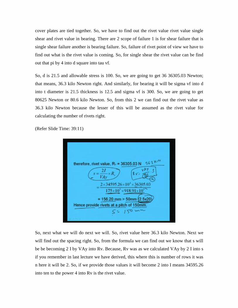
(Refer Slide Time: 39:11)
So, next what we will do next we will. So, rivet value here 36.3 kilo Newton. Next we
will find out the spacing right. So, from the formula we can find out we know that s will
be be becoming 2 I by VAy into Rv. Because, Rv was as we calculated VAy by 2 I into s
if you remember in last lecture we have derived, this where this is number of rows it was
n here it will be 2. So, if we provide those values it will become 2 into I means 34595.26
into ten to the power 4 into Rv is the rivet value.

That is 36305.03 by V is the shear force that is 175 kilo Newton. So, we are making as
Newton 175 into 10 cube Newton. And Ay Ay we have calculated here that is 918910,
918910 millimeter cube. So, 918910 millimeter cube that we are multiplying with 10
cube. So, this is becoming this right. So, after calculating this we are going to get 156.2
millimeter right and which is greater than 2.5 D as per codal provision right. So, at least it
has to be greater than 2.5 D. So, we can provide the rivets at a pitch of 150 mm, because
it is coming 156. So, we can provide pitch 150 mm. And minimum pitch has to be at least
greater than 2.5 D.
(Refer Slide Time: 41:25)
So, pitch we can find out in this way. Next what we will do next we will go for
curtailment of cover plate. So, as per IS specification the first plate is curtailed therefore,
only the top 1 will be curtailed. First plate will not be curtailed because there is 2 plate.
So, what we will do along the length. If we see that if this is the beam right and if this is
the cross section of the beam then first plate of 18 mm thickness will be provided
throughout. And then second plate will be provided somewhere right.
So, now this thickness is already decided that is 18 and this is also 18 right only this
distance has to be decided say L 1 right because L is already decided that is 7 meter right,
because of 2 plates. So, only 1 curtailment will be there here. So, in this way let us see
where we have to curtail.
(Refer Slide Time: 42:37)
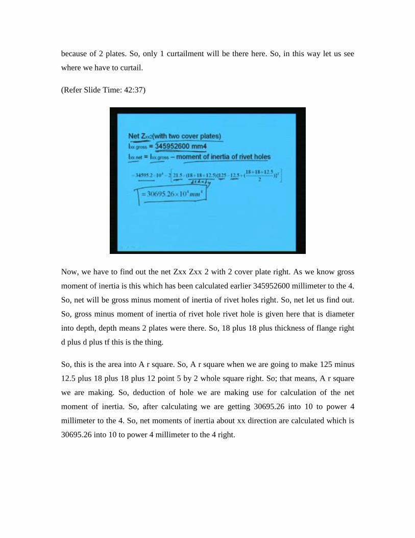
Now, we have to find out the net Zxx Zxx 2 with 2 cover plate right. As we know gross
moment of inertia is this which has been calculated earlier 345952600 millimeter to the 4.
So, net will be gross minus moment of inertia of rivet holes right. So, net let us find out.
So, gross minus moment of inertia of rivet hole rivet hole is given here that is diameter
into depth, depth means 2 plates were there. So, 18 plus 18 plus thickness of flange right
d plus d plus tf this is the thing.
So, this is the area into A r square. So, A r square when we are going to make 125 minus
12.5 plus 18 plus 18 plus 12 point 5 by 2 whole square right. So; that means, A r square
we are making. So, deduction of hole we are making use for calculation of the net
moment of inertia. So, after calculating we are getting 30695.26 into 10 to power 4
millimeter to the 4. So, net moments of inertia about xx direction are calculated which is
30695.26 into 10 to power 4 millimeter to the 4 right.
(Refer Slide Time: 44:25)
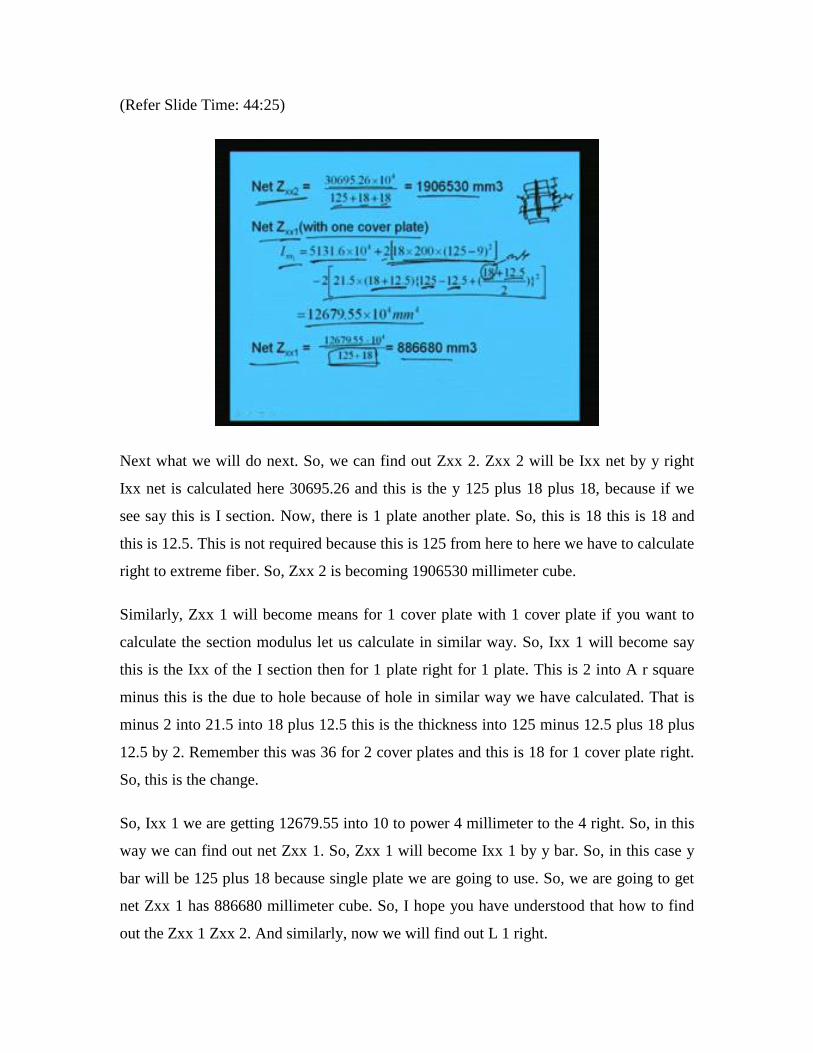
Next what we will do next. So, we can find out Zxx 2. Zxx 2 will be Ixx net by y right
Ixx net is calculated here 30695.26 and this is the y 125 plus 18 plus 18, because if we
see say this is I section. Now, there is 1 plate another plate. So, this is 18 this is 18 and
this is 12.5. This is not required because this is 125 from here to here we have to calculate
right to extreme fiber. So, Zxx 2 is becoming 1906530 millimeter cube.
Similarly, Zxx 1 will become means for 1 cover plate with 1 cover plate if you want to
calculate the section modulus let us calculate in similar way. So, Ixx 1 will become say
this is the Ixx of the I section then for 1 plate right for 1 plate. This is 2 into A r square
minus this is the due to hole because of hole in similar way we have calculated. That is
minus 2 into 21.5 into 18 plus 12.5 this is the thickness into 125 minus 12.5 plus 18 plus
12.5 by 2. Remember this was 36 for 2 cover plates and this is 18 for 1 cover plate right.
So, this is the change.
So, Ixx 1 we are getting 12679.55 into 10 to power 4 millimeter to the 4 right. So, in this
way we can find out net Zxx 1. So, Zxx 1 will become Ixx 1 by y bar. So, in this case y
bar will be 125 plus 18 because single plate we are going to use. So, we are going to get
net Zxx 1 has 886680 millimeter cube. So, I hope you have understood that how to find
out the Zxx 1 Zxx 2. And similarly, now we will find out L 1 right.
(Refer Slide Time: 47:11)
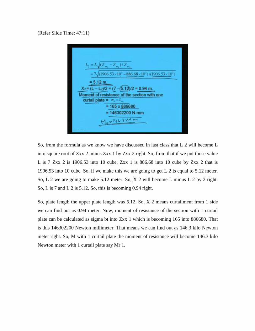
So, from the formula as we know we have discussed in last class that L 2 will become L
into square root of Zxx 2 minus Zxx 1 by Zxx 2 right. So, from that if we put those value
L is 7 Zxx 2 is 1906.53 into 10 cube. Zxx 1 is 886.68 into 10 cube by Zxx 2 that is
1906.53 into 10 cube. So, if we make this we are going to get L 2 is equal to 5.12 meter.
So, L 2 we are going to make 5.12 meter. So, X 2 will become L minus L 2 by 2 right.
So, L is 7 and L 2 is 5.12. So, this is becoming 0.94 right.
So, plate length the upper plate length was 5.12. So, X 2 means curtailment from 1 side
we can find out as 0.94 meter. Now, moment of resistance of the section with 1 curtail
plate can be calculated as sigma bt into Zxx 1 which is becoming 165 into 886680. That
is this 146302200 Newton millimeter. That means we can find out as 146.3 kilo Newton
meter right. So, M with 1 curtail plate the moment of resistance will become 146.3 kilo
Newton meter with 1 curtail plate say Mr 1.
(Refer Slide Time: 49:14)
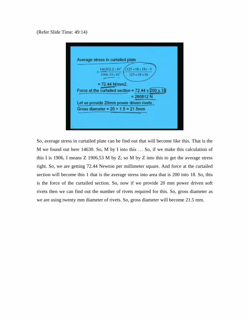
So, average stress in curtailed plate can be find out that will become like this. That is the
M we found out here 14630. So, M by I into this … So, if we make this calculation of
this I is 1906, I means Z 1906.53 M by Z; so M by Z into this to get the average stress
right. So, we are getting 72.44 Newton per millimeter square. And force at the curtailed
section will become this 1 that is the average stress into area that is 200 into 18. So, this
is the force of the curtailed section. So, now if we provide 20 mm power driven soft
rivets then we can find out the number of rivets required for this. So, gross diameter as
we are using twenty mm diameter of rivets. So, gross diameter will become 21.5 mm.

(Refer Slide Time: 50:38)
So, with this we can find out the number of rivets because as we know value of rivets in
single shear. The rivet value will become simple pi by 4 into D square into tau vf right
and tau vf will be hundred. So, after calculation we will get the rivet value as 36305.03
Newton as a single shear. And from bearing point of view similarly sigma Pf into D into t
if we make that will be becoming 80625 Newton.
So, from this 2 the lesser value will be will be the rivet value that is 636.3 kilo Newton
right. And then number of rivet will be required the force whatever it is coming by the
rivet value. So, this is becoming 7.18 say let us use 8. Now, let us … So, provide 8 rivets
of 20 mm diameter in 2 rows and minimum pitch will be 2.5 into 20 that is 50 mm right.
So, providing 8 rivets of 8 rivets of 20 mm diameter in 2 rows we can use pitch as 50 mm
right.

(Refer Slide Time: 52:00)
Then for 20 mm diameter rivets minimum edge distance is given as per codal provision
as 20 9 mm. So, let us provide a 30 mm edge distance. So, the extra length of cover plate
will become 50 plus 3 into 30 because 2 rows we have given into 2; so 2 80 mm.
Therefore, the total length of top cover plate will become 5.12 plus 0.2828 means 28 mm
280 mm. So, this is becoming 5.4 meter.
(Refer Slide Time: 52:43)

So, finally, what we are getting the details of built-up section can be like this. Say use
ISMB 250. And let us use plate size 18 by 200 by 700 mm at top and bottom throughout
at the top and bottom throughout. This is first cove plate and and plate size of 18 mm by
200 mm by 540 mm 5400 mm at top and bottom throughout for the second cover plate.
And provide 8 number of rivets of 25 diameter power driven soft rivets in 2 rows with a
pitch of 50 mm and edge distance of 30 mm. So, these are the gist of the design results.
(Refer Slide Time: 53:40)
So, now if you see the drawing we can say this is the I section. So, this is the I section
now we are going to provide 2 plate of this right. And this will be 200 this will be 18 and
18 and this is 250 this is 18, 18 right and this is 6.9. So, and this is 125. So, total depth of
the section is becoming 250 plus 4 into 18; that means, 250 plus 72; that means, 322 and
restriction was 350. So, within the restricted depth we could find out a suitable built-up
section. And across the length if we see the sections will look like this.
Say this is the I section a cover plate is given here at top and at bottom and I section this
is the flange right. And another plate is given here at top and bottom with some
curtailment. So, this is 700, 5400 millimeter means 5.4 meter and this is 7000 millimeter.
So, this is how the plate is given. So, this 1 plate and this is another this is another plate.
The first plate is the first plate is 7 meter and second plate is 5.4 meter right. So, I can

make like this right. And of course, we have to provide some rivet and rivet numbers we
have already decided pitch we have decided accordingly we have to make it right.
So, these are all rivets we have provided as per the design calculations. So, this number
has to be made properly or we have to inform here. So, in this way built-up sections can
be designed. I hope though it is very quickly I made it, because of restriction of time. I
hope you have some idea how to find out a suitable section for designing a built-up
member. Now, with this I like to conclude today’s lecture.
Thank you very much for your patience.