design of standards of inductance, and the proposed use of ... · (c) forcompounding ......
TRANSCRIPT

RP342
DESIGN OF STANDARDS OF INDUCTANCE, AND THEPROPOSED USE OF MODEL REACTORS IN THE DESIGNOF AIR-CORE AND IRON-CORE REACTORS
By H. B. Brooks
ABSTRACT
After a brief discussion of the various uses of reactors and the general charac-teristics of formulas for the self-inductance of coils, a number of useful generalrelations concerning the self and mutual inductance of geometrically similarcoils are given with illustrative derivations of some of these relations. Threeapplications of some of these relations are developed in the remainder of the paper.The first is a simple and straightforward procedure for the design of air-core coils
to serve as standards of self-inductance and is believed to be the first such designprocedure for this specific purpose to be published. The second application pro-poses that the self and mutual inductance of the large current-limiting reactorsused in power systems may be advantageously predetermined, or their computedvalues checked, by laboratory tests made on small-scale models. The thirdapplication proposes to use models for the checking or predetermination of theproperties of iron-core air-gap reactors. In developing the theory of this appli-cation it is shown that such reactors have their desirable optimum performance
—
that is, minimum power factor—when the relative length of the air gap is such asto make the copper loss equal to the core loss for the desired maximum magneticflux density in the core.
CONTENTSPage
T. Introduction 2901. Definitions 2902. Some of the uses of reactors 291
(a) As laboratory standards of inductance 291(6) In electrical instruments 291(c) For compounding synchronous converters 291(d) For paralleling transformers of unlike inherent
reactance 291(e) For limiting short-circuit currents 291
3. Objects of this paper ; 2924. The criterion, time constant 2925. General characteristics of formulas for the self-inductance of
a coil 2926. Optimum form of coil : 2937. Improved form of Maxwell-Rosa formula for the self-induc-
tance of a circular coil of rectangular cross section 2948. Convenient condensed formulas for the self-inductance of
coils of optimum form 295II. General relations concerning self and mutual inductance of geomet-
rically similar coils 296III. Design of standards of self-inductance 298
1. Range of frequencies covered 2982. Requirements to be met by standards of self-inductance for
laboratory use 2993. Procedure for the design of self-inductance standards 299
(a) General considerations affecting the design 299(b) Desired value of time constant is the starting point- _ 300(c) Design of a coil of 1 millihenry inductance 300(d) Design of a coil of any value of inductance 304(e) Deviation of actual wire from tabular data 305
(J) Checking the design values; taking care of varia-
tions ,,_, „__,._..„ 305
289

[Vol. 7
309
^90 Bureau of Standards Journal of Research
III. Design of standards of self-inductance—Continued.3. Procedure for the design of self-inductance standards—Con. pa«.
Kg) lime constant and weight of final coil _ 307(h) Numerical example of design 307(i) Design of a coil of given inductance to fill a given
spool
(7) Design of a coil of given inductance of wire of givendiameter
(k) Data for the plotting of the design curves~
310{[) Adjustment of the standard to its nominal value. 310(m) Materials for the spool; binding posts _ 311(n) Temperature coefficient of standards of inductance" 312K.O) bets of inductance coils 310
IV. Current-limiting reactors for power systems. _I_'
3131. Special requirements 313
(a) Ability to withstand heating caused by heavy over-loads 3]4
(b) Ability to withstand destructive forces during shortcircuits
314(c) High flash-over voltage ~
314o ta W Low skin-effect resistance ratio __ 3142. Design procedures in use _ __ 31 |3. Usefulness of models to designers in various" fields 3154. {suggested use of models in the design of current-limiting
reactors qia(a) Useful relations IIV___ 315
M £?ec
,
k*ng the self inductance of"full-size" re~act~ors""~ 316(c) Checking the skm-effect resistance ratio of full-size
reactors 3^7(d) Checking the mutual inductance between full-size
reactors 010(c) Checking the eleetrodynamic forces between full"
size reactors 010
v T .(/) Eleetrodynamic torque between reactors 32nV. Iron-core air-gap reactors ^0
1. Scope of this discussion _ "__ oon2. Reason for the use of an air gap lllll 3203. Condition for the desirable minimum power factor
_'"'
3214. Suggested use of model reactors as a check on present
methods of design _ 0995. Suggested use of model reactors as an"in"dVpVndVnT basis" of
design325
S? ^c?rtai?*y as to gaP reluctance, stray "flux", "etc"""
325M J^oice of form of core and location of gap 326rl
~ ce.
of core material and maximum flux density 326r \
^xpermients to be made with the model ""
326a n }?}•
W?rkmg u.P the results of experiments with the model 327
o. Condition for minimum power factor in each of a series of, rT .-••; geometrically similar reactors q97VI. Acknowledgment
328
I. INTRODUCTION
1. DEFINITIONS
J^f*ff? «#».
or f?r brevity, a reactor, is a device used for thepurpose of introducing inductive reactance in an electric circuit, and
tor^yndTg
Tld
-*? t
aVe a high time constant (ratio ofindue anceto resistance). This is because the useful property is the inductance, 1
^^^^^s^^^^o^^n^^^J not necessarily implying operation on alter-The term "reactor" h* the dtsadyrntaees oMnvnlvin^h! S.
een r,ather °™F™*ed in electrotechnics.
ambiguous to the extent that; JSctaEce^cttviMakS?™^?^6 ^5^ frequency, and is also
latter aspect is being taken care of to ™™ £?!% k ilg
'may be ei
,
ther inductive or capacitive. ThiscapacitivenBctoofm"ffl^'-XSM thi^V?5!™^ to
fpeak of a device Possessing
denser," and in line with the useful term "Tesis^rTamblgUlty of the earll*r and illogical term "con-

I
Brooks\ Standards of Inductance; Model Reactors 291
and, therefore, the reactance at a specified frequency; and the as-
sociated resistance is ordinarily either useless or detrimental. One of
the major problems in reactor design is therefore to keep the resistance
at the lowest value possible with the expenditure of a given amountof material.
For convenience, reactors may be divided into two general classes,
namely, air-core reactors and iron-core reactors. The expression
"air-core" might be replaced by "ironless." It does not exclude the
use of any material for the core or other supporting structure of the
reactor which has a permeability of unity and is either a noncon-ductor or is so arranged that eddy currents will not be set up in it.
The term "iron-core reactor" is self-defining.
2. SOME OF THE USES OF REACTORS
(a) AS LABORATORY STANDARDS OF INDUCTANCE
Reactance coils used for this purpose are of two general classes; first,
those wound on precisely measured forms in such a way that the
inductance can be computed from the dimensions; and second, coils
wound in any convenient form and adjusted to definite values of
inductance by reference to known standards. The former class will
not be considered in this paper. In both classes the coil must bewound on supports of nonmagnetic insulating material.
(b) IN ELECTRICAL INSTRUMENTS
Iron-core reactors of small size are used in frequency meters andsome other alternating-current instruments.
(c) FOR COMPOUNDING SYNCHRONOUS CONVERTERS
Larger iron-core reactors are used in the alternating-current circuit
supplying a synchronous converter in order to secure compounding.
(d) FOR PARALLELING TRANSFORMERS OF UNLIKE INHERENT REACTANCE
Transformers of like ratio but of unlike characteristics as regardsrelative resistance and leakage reactance may operate satisfactorily
in parallel on light loads but may divide heavier loads so dispropor-tionately as to overload some of the transformers seriously. Theaddition of suitable amounts of external resistance and reactance to
those transformers having relatively small values of these quantitieswill cause the load to be divided properly.
(e) FOR LIMITING SHORT-CIRCUIT CURRENTS
Probably the most conspicuous use of reactors at the present timeis for the purpose of limiting the amount of current which can flowin the generators, busses, and feeders of electric-power systems.Without the protection afforded by current-limiting reactors or someequivalent device 2
it would not be practicable to use generating unitsof the very large ratings now used because of the extremely destructiveforces and heating effects which would be caused by short-circuitcurrents.
#
2 Resistors of iron strips have been used experimentally in Germany for this purpose. They are dimensioned to have only a small temperature rise with the working current, but to approach a red heat at maxi-mum short-circuit current. The use of resistors in parallel with reactors has been investigated byKierstead, Rorden, and Bewley; see Trans. Amr. Inst. Elec. Engrs., 49, pp. 1161-1178; 1930.

292 Bureau of Standards Journal of Research [Voi.7
3. OBJECTS OF THIS PAPER
The objects of this paper are to present a number of useful generalrelations concerning the self and mutual inductance of geometricallysimilar coils, and to illustrate their usefulness by making three appli-
cations of them. The first application relates to coils serving as
standards of self-inductance for laboratory purposes. The advan-tages of the Maxwell-Shawcross-Wells optimum form of coil for this
purpose are emphasized, and a convenient and rapid procedure for
the design of such coils is given. The second proposed application
is the use of small model coils for predetermining the dimensions andperformance of large current-limiting reactors- as used in power plants.
In the third application the use of small-scale iron-core air-gap
reactors is proposed for the predetermination of the dimensions andperformance of large reactors of this type. In developing the theoryof this last application it is brought out that iron-core air-gap reactors
have the desirable minimum power factor when the length of the air
gap is such that the copper loss equals the core loss.
4. THE CRITERION, TIME CONSTANT
The unavoidable resistance of a reactor is often a disadvantage,and the wire used in its construction should, therefore, be wound to
form a coil having the greatest possible ratio of inductance to resist-
ance; that is, the highest possible time constant. 3 The circular formof coil is clearly to be preferred, and a rectangular cross section of
winding is obviously the most convenient one. It has been foundthat from the standpoint of maximum time constant the most suit-
able rectangle is a square. The remaining question to be determinedis the ratio of the side of the square cross section to the meandiameter of the winding.
5. GENERAL CHARACTERISTICS OF FORMULAS FOR THE SELF-INDUCTANCE OF A COIL
Examination of formulas for the calculation of the self-inductance
of coils will show that the self-inductance is the product of threecharacteristic factors which may best be illustrated by an example.Referring to Figure 1 (a), which shows a circular coil of rectangularcross section, Maxwell's approximate formula 4 for the self-inductance
is
L = 4iraN (l0ge |-2)
(1)
whereL = inductance in abhenries (milhmicrohenries),a = mean radius in centimeters,
N= total number of turns in the coil, andR = geometric mean distance 5 of the cross section of the winding
in centimeters.
J When it is desired to have an inductance standard which will be nearly astatic as to local magneticfield, a sacrifice in time constant must be made. For example, the coil may be wound on a supportingtorus of nonmagnetic material. A lesser degree of astaticism may be secured by the use of two coils inseries, held in a fixed relation to each other, the coils having opposite instantaneous polarities as viewedfrom one side.
* Maxwell, Electricity and Magnetism, 2, sec. 706.8 The geometric mean distance of a rectangle of sides b and c may be taken to be equal to 0.2236 '(b+c).
While the coefficient actually varies between the limits 0.2231 and 0.2237 for rectangles of various relativeproportions, the intermediate value 0.2236 gives results more than sufficiently accurate for engineeringpurposes. See B. S. Bull. 8, p. 168, 1912; Sci. Paper No. 169.

Brooks] Standards of Inductance; Model Reactors 293
The quantity in parentheses is the difference of two abstract num-bers, and is a constant for all coils of the given form having the samerelative values of a, b, and c. The three characteristic factors in theabove expression for L are the linear dimension a, the square of thenumber of turns, and the numerical coefficient whose value dependsupon the relative proportions of the coil.
6. OPTIMUM FORM OF COIL
. There are an infinite number of possible forms of circular coil of
rectangular cross section which may be made from a given lengthof wire. One extreme is formed by winding the whole length to
form a single verylarge circular turn. This gives the greatest possible
value of a, but because the inductance varies as the square of thenumber of turns the resulting inductance is far below the maximumvalue possible. The other extreme is the case of a coil in which the
— b- - «.
1
iC
1
.. 1
c7
c?
_ ...i
—b-
T
3b Zb
4b
tt WFigure 1.
—
Cross-sectional diagrams of circular coils ofrectangular cross section
(a), general form, without restriction as to relations between the valuesof a, b, and c; (6) optimum form for maximum time constant. Note thesimple and easily remembered dimensional relations in the latter,
namely, that the side of the square section, the inner diameter, meandiameter, and outside diameter of the coil are as 1:2:3:4.
radius a of the mean turn is equal to one-half the side of the squarecross section; that is, there is no hole through the center of the coil.
This also gives a value of inductance which is less than that obtain-able by an intermediate form.Maxwell investigated the question of the most advantageous form 6
of coil, but apparently did not carry enough terms of the formulahe used to locate the maximum point as well as has been done later.
He gave as the optimum form, for a coil of square cross section
(b = c in fig. 1(a)), one in which the mean diameter, 2a, equals 3.7
• Maxwell, Electricity and Magnetism, 3d ed., 2, pp. 345-346.
64825—31 6

294 Bureau of Standards Journal of Research [Vol.7
times the side b. It has since been found 7 that the relation 2a = 36,
in other words, mean diameter equal to three times the side of thesquare cross section, gives a value of L/R slightly greater (0.5 per cent)
than is given by Maxwell's proportions.
Although the inductance theoretically has its maximum valuewhen the ratio of the mean diameter to the side of the square cross
section is 2.95, the curve is so flat near the maximum that the useof the more convenient value 3 is fully warranted, as will appearfrom the following table, for which the author is indebted to Dr.Frederick W. Grover:
Table 1. -Inductance of a coil made of a given length of wire as a function ofj its form
Ratio of
meandiameterto side of
squarecross
Inductancein terms of
maximumvalue
section
2.80 0. 9996062.90 . 9999712.94 . 9999942.95 1. 0000002.96 . 9999943.00 . 9999533.10 . 999594
The form of coil given by Shawcross and Wells, with the meandiameter equal to three times the length of one side of the squarewinding channel, is a very convenient one to use for single standardsof inductance, as well as for coils which are to be assembled in a boxas resistance coils are assembled to form a rheostat. It is shown to
scale in Figure 1(b).
7. IMPROVED FORM OF MAXWELL-ROSA FORMULA FOR THE SELF-INDUCTANCE OF A CIRCULAR COIL OF RECTANGULAR CROSSSECTION
Maxwell's approximate formula, equation (1), gives for the opti-
mum form of coil a value of inductance 5 per cent higher than thatgiven by Rosa's more accurate modification 8 of Maxwell's formula.Since this modified formula, as printed in Scientific Paper No. 169,
is in an ambiguous form and involves the use of natural logarithms,
and since common (base 10) logarithms are much more convenientto use, the following equivalent formula is given. In it the symbolsa, by and c have the meanings assigned to them in Figure 1(a) and Nis the number of turns in the coil. It should be noted that this for-
mula is general as to the relative values of a, b, and c; much simplerformulas will be derived from it for coils of the optimum form.
L = 4iraN2l [2.303 log10 (35.78 jqrc )l
[l + 0.0094 (^p)
-[2 + 0.0031 (^jV]j (2)
7 Shawcross and Wells, Electrician, 75, p. 64; 1915. These writers used a formula more accurate thanthe approximate one used by Maxwell. J. Hak, Elektrotechnik und Maschinenbau, J,6, pp. 249-250; 1928,arrives at practically the same result, namely, that the mean diameter should be 2.95 times the side of thesquare cross section.
» Rosa and Grover, B. S. Bull., 8, p. 136, equation (86); 1916; Sci. Paper J^o. 169.

Brooks] Standards of Inductance; Model Reactors 295
If the linear dimension a in the quantity 4:iraN2 is in centimeters,
this formula gives the inductance in abhenries (millimicrohenries)
.
The quantity a/(b + c) and its reciprocal are abstract numbers whichdepend upon the form of the coil, but not on its size, and do not changewhen a, b, and c are expressed in other units. Consequently, for
any given form of coil, the entire expression followingN2is a numerical
constant.
While the above formula of Rosa is not rigorously exact, it is
sufficiently so for engineering purposes. Dr. Frederick W. Groverhas kindly computed the inductance of a coil, of the optimum formabout to be described, by the accurate formula of Lyle and has foundthat the above formula (2) gives a result 1 per cent lower than that
given by Lyle's formula.
8. CONVENIENT CONDENSED FORMULAS FOR THE SELF-INDUCTANCEOF COILS OF OPTIMUM FORM
From the preceding formula, equation (2), the following convenientformulas have been derived for circular coils of square cross section
having the optimum proportions, namely, the mean diameter (2 a)
equal to three times the side of the square cross section. For con-venience they are given in two groups, with the dimension a expressed
in centimeters and in inches, respectively.
Radius a measured in centimeters:
L= 16.83 a N2 abhenries (millimicrohenries) (3)= .01683 a N2 microhenries (4)= .00001683 a N2 millihenries (5)
Radius a measured in inches:
L = 42.74 a N2 abhenries (millimicrohenries) (6)= .04274 a N2 microhenries (7)= .00004274 a N2 millihenries (8)
It is obvious that the 4-figure accuracy implied by the numericalcoefficients in the preceding six formulas can not ordinarily be realized
in a or N2. The coefficients may be abbreviated by the user as
circumstances may justify. These formulas presuppose uniformdistribution of the current over the square cross section of the coil.
The design curves of Figures 3 and 4 are for the case of round wireswith insulation of negligible thickness. Although the inductancein the latter case is slightly larger than would be given by the aboveuniform-distribution formulas, the correction term for coils of 100turns or more is negligible for the present purpose. As a matter of
theoretical interest, the magnitude of the correction for any givennumber of turns in the coil may be readily found by comparing theresult given by formula (3) with that obtained from the approximatebut sufficiently accurate expression
L= 16.83 a N2 (l + ~j^) abhenries (3a)
which is formula (3) with a correction factor added.

296 Bureau of Standards Journal of Research [Voi.i
II. GENERAL RELATIONS CONCERNING SELF AND MUTUALINDUCTANCE OF GEOMETRICALLY SIMILAR COILS
The following general relations apply to geometrically similar coils
of any form whatever, located in media of equal and constant perme-ability. The coils under comparison are assumed to be closely woundof wires of the same resistivity and the same density, and (where sospecified) of the same space factor. While the relations are assumedprimarily to apply to closely wound coils, for which the diameter ofthe wire (over the insulation) determines the number of turns perlayer and the number of layers, they hold also (with obvious changesin wording) for coils "with air spaces between adjacent turns andbetween adjacent layers, if the specification of geometrical similarityincludes the cross sections of the conductors and of the air spacesabout the conductors.
(a) For coils of the same absolute size the self-inductance is pro-portional to the square of the number of turns; conversely, the num-ber of turns is proportional to the square root of the self-inductance.
(b) For coils of the same absolute size the self-inductance is inverselyproportional to the fourth power of the diameter of the wire over theinsulation ; conversely, the diameter of the wire over the insulation is
inversely proportional to the fourth root of the inductance.(c) For coils of a given self-inductance the diameter of the wire over
the insulation is proportional to the five-fourths power of a given coil
dimension; conversely, each coil dimension is proportional to the four-
fifths power of the diameter of the wire over the insulation.
(d) For coils of a given self-inductance the number of turns is
inversely proportional to the square root of a given coil dimension.(e) For coils of a given self-inductance wound with wires having
the same space factor, the diameter of the wire over the insulation is
proportional to the five-eights power of the time constant.
(/) For coils of a given self-inductance, wound with wires havingthe same space factor, each coil dimension is proportional to the squareroot of the time constant.
(g) For coils having the same number of turns the self-inductance
is proportional to the first power of a given coil dimension.
(h) For coils wound with wire of the same diameter over the insula-
tion, the self-inductance is proportional to the fifth power of a givencoil dimension; conversely, each coil dimension is proportional to the
one-fifth power of the self-inductance.
(i) For coils wound with wires having the same space factor the time-
constant L/R is proportional to the square of a given coil dimension.
(j) For coils wound with wires having the same space factor the
mass of conducting material in the coil is proportional to the three-
halves power of the time constant, and the mass of conducting material
per unit of time constant is proportional to the first power of a givencoil dimension. Large coils thus require more conducting material
per unit of time constant than small ones.
(k) For coils of a given size, wound with wires having the samespace factor, the time constant, the mass of conducting material in the
coil, and the mass of conducting material per unit of time constant
are independent of the size of the wire and, therefore, of the value of
the inductance.

Brooks] Standards of Inductance; Model Reactors 297
The following relations apply to the mutual inductance of geo-
metrically similar pairs of coils in geometrically similar relative
positions, under the same general conditions specified for the cases of
self-inductance
:
(I) For pairs of coils of the same absolute size the mutual induct-
ance is proportional to the product, primary turns times secondaryturns, for the respective pairs of coils. Note that the value of the
mutual inductance of any pair of coils does not depend, on which oneis taken as the primary.
(m) For pairs of coils of the same absolute size having a constantratio of diameter (over insulation) of wire in the primary coil to
diameter of wire in the secondary coil, the mutual inductance varies
inversely as the fourthpower of the diameter of the wires in correspond-
ing coils of the two pairs; conversely, the diameter of the wires in
corresponding coils is inversely proportional to the fourth root of the
mutual inductance.(n) For pairs of coils having the same number .of turns in corre-
sponding coils, the mutual inductance is proportional to the first
power of a linear coil dimension.Relations (I), (m), and (n) are merely extensions of relations (a),
(b), and (g) for the self-inductance of geometrically similar coils.
They indicate the manner in which relation (c) and others for the
case of self-inductance may be restated for the case of mutual induc-tance. With suitable additional limitations made necessary by themagnetic properties of iron and similar magnetic materials, generalrelations may be stated for the self-inductance of iron-core air-gap
reactors. Such of these relations as are necessary for the purposeare given later in this paper (p. 322) in discussing the proposed use of
small-scale iron-core reactors as a basis for designing full-size reactors.
Certain general relations concerning mutual translational forces andmutual torques of geometrically similar pairs of coils are developedin a later section of this paper (p. 318) on current-limiting reactors for
power systems.An obvious practical limitation, which is ignored in stating some
of the above relations, is that, in general, for an arbitrarily chosendiameter of wire over the insulation, there will not be an exactlyintegral number of turns per layer or of layers in the coil. Thismatter is readily cared for in the design and construction of actualcoils. (See p. 305.)
It is obvious that the relations above given do not exhaust the list
of possible relations of this kind, but it is believed that they includeall of the more important ones of practical applicability.
The process of reasoning by which the preceding general theoremsare demonstrated may be illustrated by giving the derivation of rela-
tions (g), (i), and (j). Assume two geometrically similar 1-turncoils, a and b, made of identical conducting material, each dimensionof 6 being n times the corresponding dimension of a. Let lay l0J says denote the lengths and cross sections of the two conductors, andRai Roj La , L b their resistances and inductances. Then we have
R b priljnha
Ra pla/Sa
from whichi?6 =Rajn

298 Bureau of Standards Journal of Research [Voi.7
The magnetic circuit of coil b has everywhere a cross section n2 timesas great as the corresponding cross section of a, and the length of eachflux path in b is n times as great as that of the corresponding fluxpath in a; hence the reluctance of the magnetic circuit of b is 1/ntimes that of a. Unit current flowing in b will thus set up n timesas many linkages as will be caused by unit current in a, which is
equivalent to the statement that
L b= nLa
If instead of one turn the conducting material now forms m turns ineach coil, both La and L b are multiplied by m2
, but L b is still n timesas great as La . This proves relation (g)
.
Coil b has n times the inductance of coil a and 1/n times the re-
sistance of coil a; hence the ratio of their time constants is
r b nLJ(Ra/n)
Ta LiallX a
from which-r b= n2Ta
which proves relation {%).
The mass of conducting material in coil b is nz times that in coil a,
and the time constant of b is n2 times that of a; hence the mass of
conducting material is proportional to the 3-halves power of thetime constant, and the mass of conducting material per unit of
time constant is proportional to the first power of a given coil di-
mension. These results prove relations (j).
While some of the general relations given above are so well knownas to be almost axiomatic, others have not been given previously, to
the writer's knowledge. Some of these relations have formed thebasis on which a simple and sufficiently accurate procedure has beendevised for the design of coils to serve as standards of self-inductance.This is believed to be the first straightforward design procedure for
this particular purpose, and will now be described.
III. DESIGN OF STANDARDS OF SELF-INDUCTANCE
1. RANGE OF FREQUENCIES COVERED
The form of coil and the design procedure about to be described are
intended to be used for frequencies of not more than say several thou-sand cycles per second. The reason for this limitation is that in addi-
tion to inductance and the usually undesirable resistance, inductancecoils have capacitance between each element of conductor surface andevery other element. The effect of this distributed capacitance is to
make the effective inductance of the coil vary with the frequency.
For the closely wound coils which are discussed in this section of this
paper, capacitance effects are small for frequencies up to a few hundredcycles per second, but may amount to several per cent for frequencies
of say 1,000 to 3,000 cycles per second. The magnitude of the effect
is greater for inductance standards of the higher values. For example,the inductance of a 1-henry standard changed 3 parts in 1,000 whenthe frequency was changed from 100 to 1,000 cycles, and 3 per cent
for a change from 100 to 3,000 cycles. For a 1 00-millihenry standardthe corresponding changes were about one-tenth of these figures.

Brooks] Standards of Inductance; Model Reactors 299
These observed results are in good agreement with the approximateformula 9
L'=L (1WCX) (9)
in which L' is the measured inductance, L the true inductance, C the
capacitance which, in parallel with the coil, would produce the sameeffect as the actual distributed capacitance, and o> equals 2-k times the
frequency.
2. REQUIREMENTS TO BE MET BY STANDARDS OF SELF-INDUCTANCEFOR LABORATORY USE
Standards of self-inductance for laboratory purposes are ordinarily
used with currents small enough not to cause appreciable heating.
The principal limiting performance consideration is usually the timeconstant LIB. The larger the coil, other things being equal, the larger
the time constant; that is, the smaller the undesirable resistance of the
coil for a given value ofinductance . The most suitable material for the
wire is copper. The ideal coil would be wound with square (or rec-
tangular) wire with insulation of zero thickness; such a coil would havea " space factor" of unity. A coil of round wire with insulation of
zero thickness, closely wound so that the turns do not imbed, 10 will
have a space factor of 0.7854. The nearest approach to the ideal
zero-thickness insulation is the so-called enamel insulation, for whichthe thickness of the insulation ranges from about 1 per cent of the
diameter of the bare wire, in the largest sizes, to about 5 per cent in
fine sizes.
3. PROCEDURE FOR THE DESIGN OF SELF-INDUCTANCE STANDARDS
(a) GENERAL CONSIDERATIONS AFFECTING THE DESIGN
The design procedure about to be described could have been workedout to apply to coils of any specified form. As given, however, it
makes use of formulas (3) to (8), and consequently is limited to
circular coils of square cross section having the mean diameter equal to
three times the side of the square cross section, as shown in Figure 1 (&).
Assuming that the currents to be carried are small, the limiting
considerations in projecting the design of an inductance standard or a
set of standards will usually be the size, weight, and cost of the coil.
The desirable operating quality, which even with the optimum form of
coil is to be had only at the expense of size, weight, and cost, is asufficiently high value of time constant. A convenient unit for this
quantity, for the present purpose, is the millisecond. 11 Small coils
for use in making up a set of four or more standards of inductancewill have a time constant of about 1 millisecond. Larger coils for useas single standards have time constants of 2 to 10 milliseconds. A
» Rosa and Grover, B. S. Bull. 3, p. 303; 1907.!<> Solenoids, by Underbill, 2d ed., p. 232.11 If a coil having a time constant of 1 millisecond is connected to a noninductive d. c. source of negligible
resistance and inductance (a storage cell is a good approximation to tbis) the current rises along a logarithmiccurve and at tbe end of 0.001 second reaches a value of (1-1/e) times its final steady value; that is, 0.632times this final value.The concept of time constant is not limited, however, to that above outlined for tbe case of growth of
current in a coil suddenly connected to a direct-current source. In the case of a coil connected to an a. c.
source of frequency f, the time constant may be regarded as the quotient of tan (equals Lu/B) by w,where a is equal to 2irf. The time constant is thus a constant of the coil which is independent of frequency(leaving out of consideration the change in skin effect with frequency) but which, with the frequency, deter-mines the angle of lag. If the time constant r=L/R of the coil is large in comparison with the period T ofthe a. c. source, the reactance of the coil predominates; if r is small compared with T, its resistance pre-dominates.

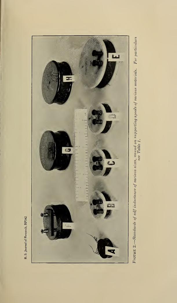
300 Bureau of Standards Journal of Research [Vol. 7
number of such coils are shown in Figure 2, to serve as illustrations ofusual practice. Particulars concerning these coils are given inTable 2.
Table 2.
—
Data on standards of inductance
Symbol Inductance ResistanceTime-con-
stantWeight
A \
Millihenries1
1
10100
1,000100100
1,000
Ohms0.75.392.88
24.2
97.010.120.896.0
Milliseconds1.32.63.54.1
10.39.94.810.4
Kilograms0.124.69.881.17
4.032.653.464.73
Pounds0.27
Bi 1.52C* 1.94Di 2.58
£3 8.9fs : 5.8G*H »
7.610.4
1 Wound on maple spool; one of the set of coils. (Fig. 8.)2 Wound on white marble spools; of German manufacture. Spools B and C are of identical dimensions.
The low value of time constant of B results from an unsuitable choice of diameter of wire, in consequence ofwhich the desired inductance of 1 millihenry is had when only three-fourths of the winding space is filled.
Note the difference in weight of the 2 coils.3 Wound on mahogany spool; of French manufacture. The binding posts might well be reduced in size,
placed closer together and farther from the axis of the coil.
* Wound on impregnated marble spool; of German manufacture. The binding posts are of the smallestpracticable dimensions. For its size, weight, and value of inductance, this coil has a low value of timeconstant because the winding is made of "litzendraht" with the intention of making the coil suitable forhigher frequencies. The space factor of litzendraht is low.
4 Wound on serpentine spool; of German manufacture. Binding posts have the good features of beingsmall, close together, and in the best possible location as regards the magnetic field.
(b) DESIRED VALUE OF TIME CONSTANT IS THE STARTING POINT
The larger the time constant, the larger, heavier, and more ex-
pensive will be the inductance standard. The representative coils
shown in Figure 2, with the accompanying data in Table 2, will
assist in the choice of a feasible preliminary value of time constant.
To simplify the work, the curves of Figures 3 and 4 have been pre-
pared, the former in metric units, the latter in English units of coil
dimensions and wire diameters. The auxiliary curve (fig. 5) applies
to either case, and is merely a method of graphically finding the recip-
rocal of the fourth power of any number within a given range.
Because of the various kinds of wire insulations, for each of which thespace factor of a winding varies, in general, with the diameter of thewire, the curves of Figures 3 and 4 are prepared for an ideal case of
round wires having insulation of zero thickness, wound closely with-out embedding of the layers. The first values taken from these
curves consequently need subsequent modification to care for thelower space factors of actual insulated wires. The manner of doingthis will be indicated. Two design procedures are described, one for
use when the desired value of inductance is 1 millihenry, the otherfor any other value L millihenries. The former case is simpler, andwill be taken up first.
(c) DESIGN OF A COIL OF 1 MILLIHENRY INDUCTANCE
The curves of Figure 3 or Figure 4 are entered with the desired
value of time constant, and preliminary values &', d', and w' of the
length of the side of the square cross section of the coil, the diameterof the wire, and the weight of copper are found. These values applyto the ideal case of insulation of zero thickness.
Reference to a table of data on wires having the desired kind of
insulation will usually show that the preliminary value d' lies
©
3©
©©CO
©>
©
60
o
1^<»
3©
e
©
8
*©
©
H
C3)-H
to

Brooks] Standards of Inductance; Model Reactors 301
too908070
60
50454035
30
25
20
s18
16
m 14
<£) 12
^> fO
< 9
CC87O
Q-j 5
4.5
*: 43.5
z 3.0
^^2.5
a: 2.0
bJ 1.6
Q. 1.6
cl 1.4
O 1.2
u 1.0
.9
b-.8
O 7
8
h- .5
1 .45
.4
.35
Ld .30
$ .25
.!0
.09
.06
.07
.05
'
-
**'
z/r
//
},f
/
*/
S /
/h,/ /
y // /
y /r^
-
/
/
///
/-
7^
//T-
/
00
ao
70
60
SO4540
35
30
25
2018
16
14
10
9
8
7
6
5
454.0
3b3.0
2.5
2.0
1.8
:.6
1.4
12
i.O
.9
.8
.7
6
oLd
Q(0
gUJI-U)
_l
z —< I)
of 9
b LdCO
< CO
OgLd(T
*OCO
I 12 14 US 1820 2.5 3.0 3.5 40 5 6 789 10 1214 16 020 25 30 40 50 60708090 100
TIME-CONSTANT IN MILLISECONDS
Figure 3.
—
Diameter of wire (over the insulation) d, side of square cross section
b, and weight of copper in coil w, in metric units, as functions of the time
constant in milliseconds, for circular coils of square cross section of optimumproportions (mean diameter of winding equal to three times the side of the square
cross section)
Denoting the time constant in milliseconds by t, and expressing o and d in millimeters and w in kilo-
grams, the equations of these curves are as follows:
6=9.142t*
d= ,6336t*
«?= .05027t*
The value of t is based on the resistivity of copper of 100 per cent purity at 25° O., and on theassumptions that ideal insulation of zero thickness is used and that there is no embedding of turns.

302 Bureau of Standards Journal of Research [Vol. 7
IOC
9C
1
—
— .—
1
80
70
* 7j7
•—A
—
5045
35
30
4.0
25 / ^-^*^ 3.0
§ S-
T^^" 2S
16
.A » 6-1.6
(/) ,41.6
Q 12 ^^ 1.4
it6
1.2
-/— 3
7 jB
.7
2 5~~ 4.5 ,.
'
^""*/
.6
.S
q: 4 °
8 2 °
5 r~ -/- —J^-.40LI -r^— .35
z.30
-.
-?»^ ?
%/1 .25
.20VJ i.a
1.6 _/ :^ .16
L- ,4 7 ^ .18
O ,., r ^ .14
TJ-
.12
^4 -^y
.09
O 7 r .08
Id f
^ ,1
.07
.06
.05
.40.04S
35/'/ 1 040
JOj035
.25 / .030
.20 - /.025
.19 -n^-J 6 / .
.14
•t2 /JO I'd
1 (2 «^4 1.6 .62.0 2.5 33 3.S4. 5 6 7 8 9 10 12 14 16
_ .
1620 25 30 40 50 ec 70 SO 30 100
<nLd
ou2Id -=
Q -z-
<Q*:&
Ldld
> DO(0
TIME-CONSTANT IN MILLISECONDSFigure 4.
—
Diameter of wire (over the insulation) d, side of square cross sectionb, and weight of copper in coil w, in English units, as functions of the timeconstant in milliseconds, for circidar coils of square cross section of optimumproportions (mean diameter of winding equal to three times the side of the squarecross section)
Denoting the time constant in milliseconds by t, and expressing 6 and d in inches and to inpounds, the equations of these curves are as follows:
6=0.3599t*
d= .02494*-^
w= .1108t*
The value of r is based on the resistivity of copper of 100 per cent purity at 25° O., and on theassumptions that ideal insulation of zero thickness is used and that there is no embedding of turns.

Brooks] Standards of Inductance; Model Reactors 303
between the diameters (over insulation) of two adjacent gage sizes.
Denoting larger 12 of these tabular diameters by du and the thickness
of insulation by tu the first revision factor di/(dr-2ti) is computed.(The quantity di~2ti is the diameter of the bare wire, and can usually
85 - 2 ^
^0±OVJ «313HVia
-2
so
eit
P s
2? °
^i 8-5
t3
00Qi CO
<5 ~
Is
ol-H
be taken directly from the table). Then a second approximationfor b is
6,, = 6U/Wi-2^1 )
Again referring to the curves, and entering with the value of b",the corresponding value of wire diameter d" is read off. If this
should happen to coincide with du wire of this diameter (over insula-
» Even if d' coincides with the diameter (over insulation) of a gage size, the diameter of the next largergage size should be used as di.

304 Bureau of Standards Journal of Research [vol. 7
tion) should be used; the value of 6" gives the side of the squarecross section of the coil, and the mean radius of the coil is a = 1.5 b"
.
If the second approximate value d" should fall between dx and thenext larger gage size, dx may be chosen if some sacrifice in timeconstant may be considered; if not, the next larger size should beused. A third possibility is that d" may fall between the diameters(over insulation) of two adjacent gage sizes, both of which are largerthan dx . Let the diameter of the one which is nearer to d" be denotedby d2 ; then a third approximation to the final value of b is
b'" = b'd2/(d2-2t2 )
The curves are again entered with this value to get the correspondingvalue d'" . If this value lies between the two adjacent gage sizes
just mentioned, one of which is d2) the smaller or the larger size is
to be chosen, according to whether one can or can not sacrifice
something in the value of the time constant. If d'" still lies betweentwo gage sizes, both of which are larger than the size used in formingthe last revision factor, this approximation process must be con-tinued until the value of d taken from the curve is less than onegage interval larger than the gage size used in the immediatelypreceding revision factor. 13 When this occurs, one or the other of
the adjacent gage sizes is selected; let its diameter (over insulation)
be denoted by dn . From the curves b ni the corresponding value of 6,
is found, and is the value to be used for the side of the square cross
section of the actual coil. It should be noted, however, that theabscissa of b n does not give the value of the time constant of the coil,
because this will have the value with which the curves were origi-
nally entered, except as modified by the compromise choice of oneor the other of the final adjacent gage sizes. Nor does the corre-
sponding value wn of the w curve give the weight of copper in the
coil. (The proof of these statements is given in a later paragraph.)The weight of copper is found by multiplying w' , the weight corre-
sponding to the first preliminary values b' and d', by the factor
dn/(dn-2tn ). This value applies to the case in which the successive-
approximation process happens to lead to an exact gage size. If a
compromise between two adjacent gage sizes must be made, theweight of copper will be greater or less than this value, as the timeconstant is greater or less than the value originally desired.
(d) DESIGN OF A COIL OF ANY VALUE OF INDUCTANCE
The procedure for the design of a coil of inductance L millihenries,
where L is not unity, is identical with the preceding except for anadditional step which must be taken each time a value of d is ascer-
tained from the curves of Figure 3 or Figure 4. That is, after enter-
ing the curves with the desired time constant and obtaining the first
preliminary values d'', b', and w', it is necessary to translate d' into
the diameter for a coil of L millihenries. This is done by using
relation (6), page 296, and to avoid computation the curves of Figure 5
18 The necessity for this succession of approximations lies in the fact that even for the same kind of insula-
tion the space factor j (d-2t)ld I usually varies from one gage size to the next. (This does not always
apply to "enamel" insulated wire, for which the space factor is sometimes closely constant over a con-siderable number of sizes.) For insulations which are wholly or partly fibrous the rate of change of thespace factor increases as the diameter decreases, and the number of approximations required in the designof inductance coils increases in consequence.

Brooks] Standards of Inductance; Model Reactors 305
may be used. Entering with L as abscissa, the value of 1/Z* is ob-
tained and d' is multiphed by it to get the first preliminary (L milli-
henry) value D' of wire diameter. Like d' in the 1-millihenry
case, this value applies for wire of zero-thickness insulation, and, like
d', it will ordinarily fall between two adjacent gage sizes. Choosingthe larger 14 of these diameters, and denoting it by A, a secondapproximation to the final value of b will be
b" = b'D1/(D1 -2t1 )
To this value b" corresponds a second approximation d" (to betaken from the curve), and d" times the value of 1/i* previously
found gives a second approximation D" to the diameter (over insula-
tion) of the wire for the desired Z-millihenry coil. In short, the only
difference in procedure, for a coil of L millihenries, is that the value
of 1/L* should be used between the obtaining of each of the succes-
sive values of 6 and the calculation of the revision factor of the formD/(D—2t). After the final wire diameter D n is selected, it is to bedivided by 1/Z* to get an equivalent 1-millihenry value dn withwhich to enter the curves of Figure 3 or Figure 4 to get the final value
bn to be used. The weight of copper is found by multiplying w' bythe final value Dn/(Dn —2t n) of the revision factor.
(e) DEVIATION OF ACTUAL WIRE FROM TABULAR DATA
If in any case the wire which is to be actually used for the coil is
found to have either of its diameters (namely, over copper and overinsulation) appreciably different from the tabular values dn anddn— 2t n used in the- design, the actual value dn should be used to find
b n , and the effect on the time constant of the variation of dn — 2tn
should be checked by the method of the next paragraph.
(f) CHECKING THE DESIGN VALUES; TAKING CARE OF VARIATIONS
The theoretical number of turns N in the coil will be b n2/dn
2, and
with this value and that of a( = 1.5 b n) the value of inductancemay be checked from the appropriate one of formulas (3) to (8),
page 295. The resistance and the time constant may then be cal-
culated. These computed check values involve four assumptions,namely, that the wire has a certain exact diameter, over the insula-
tion; that the relation between b n and dn is such that there is anexactly integral number of turns per layer and the same number of
layers; that the winding is close aod regular, and that no embeddingoccurs. In practice it is not possible to control matters so as to
produce such an ideal winding, and consequently there must be somemeans of taking care of the variations from the ideal coil. For this
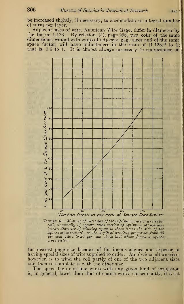
purpose the flanges of the spool upon which the wire is to be woundshould preferably be made of a diameter somewhat larger than merelyenough to accommodate a winding of square cross section. Figure 6shows the manner of variation of inductance of a coil of fixed axial
length of winding when the radial depth of winding is changed from20 per cent less to 20 per cent more than the depth for a square crosssection.
In the case of coils of relatively low inductance, in which thereare relatively few turns per layer, the value bn finally chosen should
i« Even if D' coincides with a gage diameter, the diameter (over insulation) of the next larger gage sizeshould be taken as Di.
306 Bureau of Standards Journal of Research [Vol. 7
be increased slightly, if necessary, to accomodate an integral numberof turns per layer.
Adjacent sizes of wire, American Wire Gage, differ in diameter bythe factor 1.123. By relation (b), page 296, two coils of the samedimensions, wound with wires of adjacent gage sizes and of the samespace factor, will have inductances in the ratio of (1.123)
4 to 1;that is, 1.6 to 1. It is almost always necessary to compromise on
-
150
e
U%)
^.30
0'20
5 no
^ too
«*J 90
O
gV. 70
Q.
£ 60
80 90 100 110 120
Winding Depth in per cent of Square Cross Section
Figure 6.-—Manner of variation of the self-inductance of a circularcoil, nominally of square cross section of optimum proportions(mean diameter of winding equal to three times the side of the
square cross section) , as the depth of winding progresses from 20per cent below to 20 per cent above that which forms a squarecross section
the nearest gage size because of the inconvenience and expense of
having special sizes of wire supplied to order. An obvious alternative,however, is to wind the coil partly of one of the two adjacent sizes
and then to complete it with the other size.
The space factor of fine wires with any given kind of insulationis, in general, lower than that of coarse wires; consequently, if a set

Brooks] Standards of Inductance; Model Reactors 307
of inductance coils is to be designed, all to be wound on one uniformsize of spool and to have a time constant which in no case shall beless than a prescribed value, the coil of the greatest self-inductance
should be designed first and the spool be designed to accommodate it.
(g) TIME CONSTANT AND WEIGHT OF FINAL COIL
The design curves were entered with a desired value of time con-stant for which the side of the square cross section is b
ffor wire having
zero-thickness insulation. The subsequent steps of the design haveled to higher values of b, ending with a final value bn . The time con-stant, however, does not increase with b, but retains the value withwhich the curves were originally entered, except as modified by the
J
compromise choice of one or the other of the gage sizes betweenwhich dn lies. In the following demonstration of this fact it is assumedfor simplicity that wire of diameter b n is available for the coil.
When the preliminary value V is multiplied by the final revision
factor dn/(dn-2tn ), which may be called K for brevity, the area of
cross section of the coil is increased by the factor K2. Since dn has
the same abscissa as Kb' the inductance of the coil will still be 1
millihenry because the relation of the curves is such that dn = K?d';
see relation (c), page 296. The mean radius of the coil and hence themean length of a turn increases by the factor K; the number of turnsbecomes lower by the factor K2
l{K?)2 = llIO', consequently the total
length of wire in the coil becomes greater by the factor K*. Thediameter of the bare wire becomes greater by the factor K*/K=Ki
f
hence its cross-sectional area becomes greater by the factor E3,which maintains the original value of resistance in spite of the in-
creased length of wire in the coil. The time constant thus remains at
its original value.
The mass of copper becomes greater by the product of the factors
of increase of length, K*tand that of increase of area, K*\ that is,
the actual coil of wire diameter (over insulation) dn and thickness of
insulation tn , while of the same resistance and inductance as theideal coil of wire diameter d' with zero-thickness insulation, has amass of copper which is greater than the ideal value w' by the factor
K=dJ(dn -2tn ).
(h) NUMERICAL EXAMPLE OF DESIGN
A coil of 100 millihenries is to be wound of copper wire insulatedwith "enamel" and one covering of silk, and is to have a time con-stant of 3 milliseconds. Required the size of the wire, the dimensionsof the coil, and the weight of copper composing it. The curves of
Figures 4 and 5 will be used. Entering the curves of Figure 4 withr = 3 milliseconds,
From Figure 5
whence
b' = 0.625 inchd' = 0.0495 inchw' = 0.575 pound
1/J> = 0.320
B' = 0.320X0.0495= 0. 0158 inch

308 Bureau of Standards Journal oj Research [Vol.7
From a table for a particular make of this kind of insulated wire thefollowing data are extracted:
Size, American Wire Gage
Diameter bare wire... inches..Diameter over insulation. doResistance at 25° C. per 1,000 feet ohms..Weight per 1,000 feet pounds..
25 26 27 28
0. 0179 0. 0159 0. 0142 0. 0126.0216 .0195 .0176 .0160
33.0 41.6 52.5 66.2.970 .769 .610 .484
It may be seen that D' nearly coincides with the diameter (over insu-
lation) of No. 28 wire. That of No. 27 is taken as Du and the first
value of the revision factor is
Hence
Di/(A -2tx ) =0.0176/0.0142= 1.239
b" =b /D1/(D1-2tl )
=0.625X1.239=0.775 inch
Curve d of Figure 4 is entered with this value and d" is found to be0.0640 inch. Then
D" =0.320x0.0640=0.0205 inch
This value lies midway between the figures for No. 25 and No. 26.
For No. 25,
D2/(D2-2t2 ) =0.0216/0.0179= 1.207
bf" =b ,B2l{D2 -2t2) =0.625 Xl.207
=0.754 inch
Curve d of Figure 4 is entered with this value, and dnr is found to be0.0622 inch. Also
£>'" =0.320x0.0622=0.0199 inch
This value lies between the same pair of gage sizes as D", hence the
choice of the wire to be used for the coil lies between No. 25 and No.26. D'" is much closer to No. 26, and the choice of the latter will
give a value of time constant which, while below the desired value,
will be the closer approximation to it. D3 is now taken as 0.0195
inch, from whichdz=pj(i/m= 0.0195/0.320=0.0610 inch
Corresponding to this value in Figure 4 is the value 63 =0.741 inch, the
value to be used for the side of the square cross section. The meanradius of the coil is a = 1.56 =1.5 X 0.741 equals 1.111 inch, and the
over-all diameter of the coil is 46 =2.964 inches.
Check
:
7V=(0.741/0.0195) 2 =1,444 turns
a = 1.111 inch£=0.00004274aiV2
= 0.00004274X1. Ill X(l,444) 2
=99.1 millihenries

Brooks] Standards of Inductance; Model Reactors 309
The length of wire in the coil is
27raiV=6.283 Xl.lll X 1,444= 10,085 inches=840 feet
The resistance at 25° C is
5=0.840x41.6=34.9 ohms
and the time constant is
t=L/R=99.1/34.9=2.83 milliseconds
The weight of copper in the coil is
0.840 X0.769 =0.646 pound
If No. 25 wire had been chosen, the following results would beobtained
:
d3 = 0.0216/0.320=0.0675 inch
From Figure 4, for this value of d3
b3 =0.802 inchCheck
:
iV=(0.802/0.0216) 2 =1,379 turnsa =1.55 =1.5x0.802= 1.203 inch
L =0.00004274 X 1.203 X (1,379)2
=97.7 millihenries
The length of wire in the coil is
27raiV = 6.283 Xl.203 Xl,379= 10,420 inches=868 feet
Its resistance at 25° C. is
0.868 X33.0 =28.66 ohms
and its time-constant is
r =97.7/28.66=3.41 milliseconds
The weight of copper in the coil is
0.868 X0.970 =0.842 pound.
(i) DESIGN OF A COIL OF GIVEN INDUCTANCE TO FILL A GIVEN SPOOL
If a spool of the optimum proportions of given size is to be woundto have a given inductance, the curve b is entered with the value of
b for this spool. The corresponding value of d gives the diameter of
the wire (over the insulation) to be used for an inductance of 1 milli-
henry. For any other value of L this value of d is to be multiplied bythe appropriate value of 1/Z* from Figure 5.
64825—31 7

310 Bureau oj Standards Journal of Research [voi.7
(j) DESIGN OF A COIL OF GIVEN INDUCTANCE, OF WIRE OF GIVEN DIAMETER
In this case, for a coil of 1 millihenry, the curve d is entered withthe given diameter of wire (over the insulation) and the correspondingvalue of b is the side of the square cross section of the coil. For acoil of L millihenries, the given diameter is first to be multiplied byZ>; that is, divided by the value of 1/L* taken from one of the curvesof Figure 5.
(k) DATA FOR THE PLOTTING OF THE DESIGN CURVES
The curves of Figures 3 and 4, plotted on large sheets of logarithmiccoordinate paper, will permit more convenient interpolation than is
possible with the small-scale figures »of this paper. The curves are
nominally straight lines having the following equations, in whichb
yd, and w have the same meanings as in Figures 3 and 4, and t denotes
the time constant in milliseconds
:
Metric units ; b and d in mm, w in kg
:
b =9.142 r*, d =0.6336 r*, w -0.05027 r* (10)
English units ; b and d in inches, w in pounds
:
6=0.3599 t*| d =0.02494 r», w =0.1108 r* (11)
The numerical coefficients in these six equations are based on thefollowing data: Density of copper, 8.89; resistance between oppositefaces of a centimeter cube of copper at 25° C, 1.757 microhms.(These figures correspond to 100 per cent conductivity, International
Annealed Copper Standard.)Because of slight imperfections in the coordinate paper, it is best
to plot more than two points and to draw the curve through theplotted points rather than as a strictly straight line. Each of thecurves of Figures 3 and 4 was drawn through computed points for
r = l, 3, 10, 30, and 100 milliseconds. These computed values are
as follows:
T=l 3 10 30 100 milliseconds
6=9.14 15. 83 28.91 50. 1 91. 4 millimeters= .360 623 1. 138 1.971 3. 599 inches
d = .634 1. 259 2.672 5.31 11. 27 millimeters= .0249 . 0496 . 1052 .2090 . 444 inches
w= .0503 2612 1.590 8.26 50. 3 kilograms= . Ill 576 3.50 18.21 110. 8 pounds
(1) ADJUSTMENT OF THE STANDARD TO ITS NOMINAL VALUE
Since the two binding posts are preferably to be located close to-
gether in order to avoid forming a loop when making connections to
the standard, one is, in general, restricted to an integral number of
turns. In general, therefore, a coil of N turns would have to be left
with an error of 1/iV part 15 of its nominal value. For coils of a large
number of turns this degree of precision of adjustment may besufficient. Where the number of turns and the inductance are small,
15 The worst case would be where the nominal value required that the number of turns differ from anintegral number by one half-turn; since the inductance varies as the square of the number of turns, the effect
of a half-turn in N turns is one part in iSTin inductance. This is an approximate statement only, because theeffect of an outside turn is, in general, different from that of a mean turn.

Brooks] Standards of Inductance; Moael Reactors 311
some means for obtaining closer adjustment is necessary. One wayof doing this is illustrated in Figure 7. A circular recess is made in
the spool, into which opens the small hole, through which the starting
end of the wire is passed. After the coil is wound, and adjusted to
the nearest whole (outside) turn for which the inductance is either a
little low or a little high, the wire near the starting end may be madeinto a little coil within the recess, in inductive relation to the main coil,
and any desired precision of adjustment obtained. This methodalso provides for subsequent readjustment if necessary. The small
coil may be protected from derangement by a suitable cover for the
circular recess in which it lies.
Figuke 7.
—
Form or spool for standard of self-inductance, showing circular
recess within which the inner end of the winding may he coiled to effect the
final precise adjustment of inductance.
(m) MATERIALS FOR THE SPOOL; BINDING POSTS
Coils to be used as standards of inductance have been wound onforms or spools of various materials. Mahogany saturated withparaffine has been used to a limited extent. German makers at onetime used serpentine, but in the case of certain coils, this was later
shown 16 to be slightly magnetic and, therefore, unsuitable. Whitemarble is free from this defect, and its expansivity appears to be close
to the desirable value, but it has the undesirable property of irrever-
sible growth 17 when heated above room temperature.Porcelain 1-piece spools have been used to a limited extent. Porce-
lain has valuable properties for this purpose. The linear expansivityof various kinds of porcelain has been found 18 to vary from about 3 to
20 parts per million per degree C, a range which includes the valuefor copper. Porcelain of such composition as to have approximatelythe expansivity of copper should be very suitable. Porcelain is free
from the phenomenon of growth noted in marble.Phenol condensation products, such as bakelite, condensite, etc.,
as a rule, have expansivities exceeding that of copper, and they shrinkif kept at temperatures above 60° C. The expansivity of mahogany
" Rosa and Grover, E. S. Bull. 3, pp. 337-348; 1907; Reprint No. 15.
" Souder and Hidnert, B. S. Bull. 15, pp. 411-416; 1919-20; Sci. Paper No. 352." Souder and Hidnert, B. S. Bull. 15, pp. 391-398; 1919; Sci. Paper No. 352.

312 Bureau of Standards Journal of Research [voi.7
across the grain is more than twice that of copper; with the grain,
about one-fifth that of copper. All untreated woods are, of course,
objectionable because they change form as their moisture contentchanges. Hard rubber and vulcanized fiber are objectionable becausetheir expansivities are four or five times those of copper, and vul-
canized fiber swells and warps when exposed to moist air.
While the size and location of binding posts is usually a matter of
mere convenience and appearance in most electrical apparatus, it is
not so in the case of standards of inductance. To minimize the effect
of eddy currents the binding posts should be made of metal of highresistivity and should be as small as is consistent with other require-
ments. The posts should be located where the magnetic field of thecoil has a relatively low value, not only to minimize eddy-currenteffects but also in order to keep down the mutual inductance be-tween the coil and any loop formed by the wires which will run to
the binding posts. Examples of good construction in this respect are
standards G and H in Figure 2. Some makers have in the past lo-
cated heavy brass binding posts in the worst possible place, namely,near the axis of the coil.
(n) TEMPERATURE COEFFICIENT OF STANDARDS OF INDUCTANCE
If the copper in an inductance standard is free to expand withincreasing temperature, without constraint, so that the whole massof wire and insulation changes form as it would if of solid copper, it
follows from relation (g), page 296, that its temperature coefficient of
inductance will be the same as the linear expansivity of copper,namely, about 17 parts per 1,000,000 per degree C, which is of coursenegligible for most applications. Experimental data on the actual
temperature coefficient of inductance standards seem to be lacking.
(o) SETS OF INDUCTANCE COILS
When a number of inductance coils are to be assembled in a box,
they should be arranged so that the mutual inductance between coils
will be very small. Three coils, assembled in a row with their planesmutually perpendicular will have zero mutual inductance betweenany pair. After the first coil is mounted in position, the second coil
can be readily located in the position of zero mutual inductance bypassing an alternating current through the first coil, attaching a tele-
phone receiver to the second coil, and securing the latter in a position
such that there is no sound in the receiver. Then each of the first
two coils can be used as a primary and the third coil can be located in
the position which gives silence in the receiver in each case. A fourthcoil can be located to have zero mutual inductance with respect to
coils 2 and 3 but necessarily has some mutual inductance with coil 1.
However, the mutual inductance between two coils decreases veryrapidly 19 as their distance apart increases.
Figure 8 shows a set of 8 standards of self-inductance, consist-
ing of 2 rows of 4 coils, each row being mounted in the mannerjust described. To reduce mutual inductance between the coils of
one row and those of the other to a negligible amount,the rows are
separated as shown. Eight noninductive copper coils also are pro-vided, each adjusted to have the same resistance as one of the induc-
18 Approximately, the mutual inductance varies inversely as the cube of the distance between the coils,
when this distance is large compared with the diameter of the coils.

B. S. Journal of Research, RP342
Figure 8.
—
Set of eight standards of self-inductance
, Complete in case; 6, removed from case. The coils in one row have the values1, 2, 3, and 4, millihenries; in the other, 10, 20, 30, and 40 millihenries. The coils
in each row are located to minimize mutual inductance between coils, and thetwo rows are spaced far enough apart to make mutual inductance between rowsnegligibly small. The pair of flexible leads with "traveling plugs" is for usewhen connection is to be made (for special purposes) to one or several of the indi-vidual coils.

Brooks] Standards of Inductance; Model Reactors 313
tive coils. The plug switchboard makes it possible to cut into circuit
any one or more of the inductive coils and to replace those out of
circuit by their corresponding noninductive coils. The total resist-
ance between the terminals is thus kept constant, regardless of thevalue of the inductance. This feature is convenient when the set is
used in one arm of an inductance bridge. The switchboard is com-posed of regular commercial radio parts, namely, 16 "short jacks"and 8 " duplex plugs." Each of these plugs has its two contact parts(tip and sleeve) short-circuited within the handle. A plug inserted
in any hole in the upper row (marked "In") inserts the correspond-ingly numbered inductive coil; in the lower row, the noninductivecoil.
In some cases it is desirable to use one or several of the inductivecoils of the set without including in the circuit any unnecessaryresistance. The flexible leads shown in Figure 8 are for this purpose.One lead is connected to the tip of its plug, the other to the sleeve of
its plug. Single coils, either inductive or noninductive, may bepicked out with these "traveling plugs." If several coils in series
are wanted, the traveling plugs are used in conjunction with one ormore of the regular (short-circuited) plugs. Other connections are
possible; for example, connections may be made to any coil to beused as a primary coil and to any other to serve as a secondary.This permits the checking of the mutual inductance between the coils
to see whether it is sufficiently low (with respect to the sum of their
self-inductances) to be negligible.
As compared with an equal number of single standards of induct-ance, such a set of standards has the advantage that the mutualinductance between each coil and every other one is small and fixed.
In using a number of single standards care must always be exercised
to keep them far enough apart to make the mutual inductance negli-
gible; and this precaution may easily be neglected by inadvertence.The set of coils has the further advantage of requiring less table spacewhen in use. It has two disadvantages, namely, the greater storagespace occupied when the set is not in use, and the fact that the indi-
vidual coils can not be used in different places on occasion.Two sets of inductance coils, of much larger dimensions than the
ones shown in Figure 8, are used in the current-transformer laboratoryof the National Bureau of Standards in the setting up of artificial
burdens. With 8 coils ranging from 10 to 500 microhenries, anyvalue of inductance from 10 to 1,100 microheuries can be used. Toobtain the highest practicable time constant with a given cost for
copper, the coils were wound with square 20 copper wire. The time-constants range from 2.5 milliseconds for the 10-microhenry coil to 17milliseconds for the 500-microhenry coil.
IV. CURRENT-LIMITING REACTORS FOR POWER SYSTEMS
1. SPECIAL REQUIREMENTS
Inductance coils of large size, known as current-limiting reactors(protective reactors), must meet certain extraordinary requirementswhich make it impracticable to construct them in the closely woundform described in the preceding section of this paper. In spite of
*• The side of the square cross section of the wire is 0.162 inch.

314 Bureau oj Standards Journal of Research [Voi.7
the fact that a high time constant is just as desirable in a protectivereactor as in an inductance standard for laboratory purposes, andthat departure from the optimum form involves an extra cost for
copper for a given inductance, the other considerations compel adeviation from the optimum form. These requirements and their
effect on the design of protective reactors will be briefly mentioned.
(a) ABILITY TO WITHSTAND HEATING CAUSED BY HEAVY OVERLOADS
A protective reactor is of service only in an emergency, namely,in case of a heavy overload or a short-circuit on the line in which it is
placed. It must be able to carry currents of the order of 25 timesrated current for, say, five seconds. During this interval the rate of
development of heat in the reactor winding is approximately 625times its usual value. It is obvious that instead of the closely woundturns and layers of the inductance standard used in the laboratorythe protective reactor must have its turns and layers spaced apartto allow free passage of air either by convection or forced circulation.
(b) ABILITY TO WITHSTAND DESTRUCTIVE FORCES DURING SHORT-CIRCUITS
Like the heating effect, these forces increase as the square of thecurrent, and require the use of strong constructions. The turns andlayers may be spaced apart and held by strong cleats of heat-resisting
insulating material, or they may have concrete supports cast aroundthem.
(c) HIGH FLASH-OVER VOLTAGE
Although the voltages from turn to turn and layer to layer are
relatively small during normal operation, they attain large valuesduring short-circuits or transient disturbances of high frequency.The spacing between turns and layers serves not only to permitescape of heat, but provides the necessary separation to avoid flash
over.(d) LOW SKIN-EFFECT RESISTANCE RATIO
This requirement is important to minimize the copper loss in thereactor during normal operation. Stranding the conductor, and in
some cases enameling 21 certain combinations of the cable strands,
are used for this purpose. When several cables are used in parallel
to form the reactor winding they are symmetrically spaced and woundso that the total current will be equally divided and circulating cur-
rents will be avoided.
2. DESIGN PROCEDURES IN USE
The inductance of current-limiting reactors is determined in somecases by means of standard formulas, 22 such as those of Lorenz,Nagaoka, Rosa, Stefan, and Grover, and in other cases by means of
formulas which, while based on standard formulas, also involve theuse of families of curves from which values may be found by inter-
» Robert B. George, Tbe Application of Current-limiting Reactors, Electric J., 26, pp. 29-38; January, 1929.22 Lorenz's formula is given as equation (74), p. 118; Nagaoka's formula, equation (75), p. 119; Stefan's
formula, equation (90), p. 137; Rosa's correction formula, equation (91) p. 139; all of B. S. Sci. Paper No. 169
(part of vol. 8); Grover's formula No. 4 is given on p. 458 of B.S. Sci. Paper No. 455 (part of vol. 18). See also
paper by Grover on Formulas and Tables for the Calculation and Design of Single-Layer Coils, Proc. Inst.
Radio Engrs., 12, pp. 193-208, April, 1924.

Brooks] Standards of Inductance; Model Reactors 315
polation with an accuracy sufficient for engineering purposes.23
The consideration of these methods is outside the scope of the presentpaper, in which it is desired to suggest the possible uses of small modelcoils made to scale. The standard formulas usually involve consider-
able calculation, and for some forms of coil do not converge rapidlyenough; the sets of curves may not cover the particular proportionsof length and diameter of coil and spacing of conductors for a pro-posed new and different design; the mutual inductance between adja-cent reactors is not easy to calculate and introduces an unbalancingof phase voltages,24 and the internal short-circuit forces 25 and thosebetween neighboring reactors are not readily calculated. In all of
these matters it is felt that laboratory measurements on model reactors
may be useful, not only in checking design values obtained by presentmethods, but also for determining quantities (such as skin-effect
resistance ratio) which are not only difficult to compute in advance,but also difficult to measure in the actual reactors.
3. USEFULNESS OF MODELS TO DESIGNERS IN VARIOUS FIELDS 24
Many problems of engineering design are too complicated for solu-
tion by ordinary mathematical methods and must be solved by experi-
ment; but it often happens that the desired information can beobtained from inexpensive experiments on small models quite as well
as from full-scale tests.
The classical example of this is the utilization by naval architects
of the results of towing-tank experiments on models for predicting
the resistance-speed curves of proposed ships; and in recent years theprogress of airplane design has been largely dependent on informationobtained from tests of models in the wind tunnel. Similar methodshave also been used for studying the erosion of stream beds neardams or bridge piers, the formation of sand banks in tidal estuaries,
etc.
Model experiments are particularly useful in hydraulics and aero-
dynamics because the mathematical treatment of the problems thatarise nearly always presents insuperable difficulties; but the utility
of the method is not confined to the field of fluid motion or of mechan-ics in general—it is also applicable to many problems in electrical andheat engineering, and it is believed that experiments on small modelsmay be of service to the designer of large commercial reactors.
Whatever the shape or general design of an electrical apparatusmay be, its mechanical and electromagnetic properties depend on its
absolute size and will be affected in definite ways by a mere changeof scale of the whole apparatus, in all its parts, without changing thematerials of construction. For the planning and correct interpreta-tion of model experiments the designer, therefore, needs a number of
relations connecting the various characteristics in which he is inter-
ested with the size, when the shape, number of windings, etc., arefixed.
23 See H. B. Dwight, Elec. J., 15, pp. 166-168; 1918; Trans. Am. Inst. Elec. Engrs., 38, pt. 2, pp. 1678-1696;1919; Elec. J., 19, pp. 268-270, 1922; S. L. Oesterreicher, Trans. Am. Inst. Elec. Engrs. 43, pp. 892-901;1924; A. Ytterberg, Elektrot. Zeit., 36, pp. 309-311, 325-327; 1915; O. Gramisch, Elektrot. und Masch., 46,pp. 105-110; 1928; J. Hak. Elektrot. Zeit., 50, pp. 193-198; 1929; K. Faye-Hansen, Elektrot. Zeit., 51, pp.427-429* 1930." H. B. Dwight, Trans. A. I. E. E., 38, pt. 2, pp. 1679-1681, 1919.2« W. M. Dann, The Mechanical Stresses in Reactance Coils, Elec. J., 11, pp. 204-207; 1914; H. B. Dwight,
Repulsion and Mutual Inductance of Reactors, Elec. World, 69, pp. 1148-1150; 1917; and Trans. Am. Inst.Elec. Engrs., 38, pt. 2, pp. 1681-1684; 1919.* This section has been contributed by Dr. E. Buckingham, to whom the writer is indebted for valu-
able suggestions for the improvement of this paper.
316 Bureau of Standards Journal of Research \voi. 7
4. SUGGESTED USE OF MODELS IN THE DESIGN OF CURRENT-LIMITING REACTORS
(a) USEFUL RELATIONS
Most of the relations needed in this part of the paper have beengiven in Part II (p. 296) as relations (a) to (k), inclusive, and in thefollowing discussion of the uses of models they will be referred to bythese letters. In applying these relations to the case of protective
reactors, however, an important distinction between these reactors
and the small standards of inductance previously discussed shouldbe kept in mind, namely, that the latter (for the relatively low fre-
quencies considered in^this paper) are closely wound with insulated
wire, so that the diameter of the wire over the insulation has a direct
relation to the number of turns to fill a given channel. Protectivereactors, on the contrary, usually have air spaces between adjacentturns and adjacent layers. The diameter of the wire over the insu-
lation (if any) has, therefore, no direct relation to the inductance of
the coil. However, relations (b), (c), (e), and (h) will still apply if for
the "diameter over the insulation" one substitutes the square root of
the product of the axial pitch by the radial pitch. 27If we define the
space factor of a reactor as the ratio of the net cross section of theconductor to the area of a rectangle of which the sides are, respectively,
the axial pitch and the radial pitch, relations (e), (f), (i), (j), and (k)
apply to coils in which open spaces separate turns and layers.
Another important distinction between the inductance standardand the current-limiting reactor must be noted. The diameter of
the wire used in the former is usually so small (with respect to thefrequency range to which this paper is limited) that the increase of
resistance from skin effect is not serious. In current-limiting reac-
tors, however, the wires or cables are often of relatively large cross
section and the skin-effect resistance ratio may be of considerableimportance even at the relatively low frequencies on which they are
used, since the PR loss in the reactor during normal operation is pro-portional to it. The direct measurement of the PR loss is a some-what difficult matter because of the large currents and the very lowpower factor. A special procedure, which will be described later,
makes it possible to produce and measure, in the model reactor, askin-effect resistance ratio equal to that in the full-size reactors.
Current-limiting reactors, in this country, are usually connectedin circuits of frequency not exceeding 60 cycles per second, conse-quently the effect of distributed capacitance may be neglected, so far
as effects of operating frequency are concerned.
(b) CHECKING THE SELF-INDUCTANCE OF FULL-SIZE REACTORS
To check the predetermined value of self-inductance of a proposedreactor, a model reactor is made in which all significant dimensionsare 1/n times those of the proposed reactor. This factor applies to
the copper conductor as well as to the axial length of coil, diametersof successive layers, etc. The conductor should be stranded in thesame manner as the full-size conductor will be, in order that the same
*7 For coils in which the conductor is wound as a succession of layers the axial pitch is the distance fromcenter to center of adjacent turns in a layer, measured in a direction parallel to the axis of the coil, and theradial pitch is, in general, the radial distance between adjacent imaginary cylinders which are coaxialwith the coil, each cylinder bisecting the cross section of the conductors of a given layer. The terms axialpitch and radial pitch may be applied, with obvious modifications, to coils which are wound as a series
of coaxial flat spirals or "pancakes."
Brooks] Standards of Inductance; Model Reactors 317
model may be used to get the skin-effect resistance ratio also. Thenumber of turns in the model should be the same as in the proposedreactor. Then by relation (g), page 296, the inductance of the full-
size reactor will be n times that of the model. Neglecting skineffect, the d. c. resistance of the full-size reactor will be 1/n times thatof the model. This resistance, however, can be so easily computedfor the full-size reactor that there would be no object in making amodel, so far as it is concerned.
(c) CHECKING THE SKIN-EFFECT RESISTANCE RATIO OF FULL-SIZE REACTORS
To determine the skin-effect resistance ratio for the full-size
reactor, this ratio is determined for the model, using a frequency n2
times the rated frequency of the full-size reactor.28 The use of this
value of frequency depends upon the fact that the skin-effect resistance
ratio (that is, the ratio of a. c. resistance to d. c. resistance) for aconducting structure is a function of one parameter, fd2
fi,/p, where/denotes the frequency, d a given linear dimension,
fj,the permeability
(equal to unity for air and for copper) and p the resistivity of theconductor material. While the form of the function depends on theshape of the structure, this form is the same for all geometricallysimilar structures of any size or material.
For example, if the proposed full-size reactor is to operate at 60cycles, and the model is made with each linear dimension one-tenththat of the full-size reactor, the model should be tested for skin-
effect resistance ratio at 6,000 cycles. It should be noted that inthis case it is especially important that the model be wound with aconductor which has the same number of strands (or straps) as theconductor of the full-size reactor, each strand (or strap) having its
dimensions 1/n times those of the conductor of the full-size reactor.
The arrangement of the winding and the number of turns must bethe same in the model as in the full-size reactor. If the individualcomponents of the full-size conductor are insulated from each other,
those of the conductor on the model should also be insulated, and theover-all dimensions of the conductor on the model should be 1/n ofthose of the full-size conductor. While these precautions involvesome extra pains in construction, the result of the test gives a figure
which would otherwise have to be found by the difficult procedure ofmeasuring the very low power factor of the large current of thefull-size reactor.
If it should not be convenient to make the test of the model re-
actor at n2 times the working frequency, it may be made at a different
frequency and corrected by using the fact that Ar/r, the relative in-
crease of resistance caused by skin effect, varies for low frequenciesalmost exactly as the square of the frequency, and that AL/L, therelative change of inductance with frequency, is usually very smallcompared with Ar/r.
It is worth noting, as pointed out by Dwight, that the preceding useof a model is applicable to other cases where the inductance and theskin-effect resistance ratio of large conducting structures, for example,busbars and furnace leads, are of importance and are not readily pre-determined by calculation.
28 This expedient was suggested by H. B. Dwight, Trans. Am. Inst, of Elec. Engrs., 37, pt. 2, p. 1399;1918. A more mathematical proof of the theorem was given by Joseph Slepian in the discussion of Dwight'spaper, same volume, pp. 1401-1403.

318 Bureau of Standards Journal of Research [Vol. 7
(d) CHECKING THE MUTUAL INDUCTANCE BETWEEN FULL-SIZE REACTORS
If a small-scale model of two or more reactors is made with all the
dimensions, 29 including the distances between the reactors, reduced to
1/n times their original values, the number of turns in each modelreactor being the same as in the corresponding full-size reactor, the
mutual inductance between any pair of reactors will be 1/n times the
mutual inductance between the corresponding full-size reactors.
The mutual inductance is so nearly independent of frequency 30 that
its value may be determined with any convenient frequency.
The practical importance of a knowledge of the mutual inductancebetween protective reactors depends mainly on two effects which it
produces. The first of these is an unbalancing of phase voltages for
cases where the reactors A, B, and C, are unsymmetrically grouped;that is, where the three mutual inductances MAb, MBc, Mac are un-equal. As examples of usual unsymmetrical groupings may bementioned, first, all three reactors having a common vertical axis;
second, all three axes vertical and in a common vertical plane, and the
centers of the coils in the same horizontal line.31
(e) CHECKING THE ELECTRODYNAMIC FORCES BETWEEN FULL-SIZE REACTORS
These forces constitute the second effect of practical importanceresulting from the mutual inductance between the parts of thewinding of a given reactor, or between adjacent reactors. Increas-
ing as the product of the currents in the two reactors (times the cosine
of the time phase angle between the currents), these forces may be-
come relatively very high 32 during short circuit conditions. Theuse of model reactors for determining the translational forces be-
tween full-size reactors depends upon an ideally simple relation whichapplies to geometrically similar pairs of coils or other conductingstructures, and which will now be developed.The force Fx in any direction x between any two circuits traversed
by currents Ix and I2 which are displaced in time phase by an angle
6 is given by the well known formula
Fx=%%cosfi^ (12)
Referring to Figure 9, let the curve MM'N represent the mutualinductance between two coils as a function of the distance (in thedirection x) between their axes. The ordinate MX, corresponding to
the axial distance OX, is the maximum possible value of mutualinductance, and is for the case of coils in contact. As the distancebetween the axes increases the mutual inductance decreases as
shown by the curve MM'N, and for any given value of I\ I2 cos theforce in the direction x will be proportional to the slope of this curve.
29 An exception is the diameter of the conductors; it is not necessary, in the determination of mutual in-ductance, to adhere at all closely to proportionality of conductor diameter, nor do the conductors need to bestranded or enameled as for the previous case where the skin-effect resistance ratio was an important itemto be determined.
30 This statement would not apply accurately to extreme cases where the two circuits are very closelycoupled; for example, two coaxial disk or "pancake" coils separated by a relatively small axial distance.Such a case would hardly be even approximated, as far as the protective reactors under consideration areconcerned.m This second case is treated by H. B. Dwight, with a numerical example, in Trans. Am. Inst. Elec.
Engrs., 38, pt. 2, pp. 1675-1G81; 1919.31 Kierstcad and Stephens, Trans. Am. Inst, of Elec. Eng., 43, p. 909; 1924; report having observed forces
as high as 33,000 pounds. They state that in the case of average feeder reactors the force is not over 10,000pounds.

Brooks] Standards oj Inductance; Model Reactors 319
Consider now a second pair of coils, geometrically similar to thefirst pair, similarly located with respect to each other, with the samenumber of turns in corresponding coils, but with all the dimensionsreduced to 1/p times those of the first pair. By relation (n), page 297,the mutual inductance of this second pair of coils for any relative
position will be 1/p times the mutual inductance of the larger pairfor the corresponding position. The values of mutual inductance of
the smaller pair, plotted to the same coordinates as the curve MM'N(fig. 9), will give the curve mm'n, in which mx is the maximum possible
ordinate, for coils in contact, and corresponds to the ordinate MX for
the larger coils. Since the two curves have their correspondingabscissas differing only by the constant factor 1/p, and their cor-
responding ordinates also differing only by this same factor, the
to Jo
r to
£|s* +-
C5 to
* ? X ^Distance x Between Reactor Axes
Figure 9.
—
Manner of variation of the mutual inductance of two
pairs of reactors as a function of the distance between their par-
allel axes
The smaller curve ran refers to a pair of coils geometrically similar to a larger pair to
which the curve MN applies. For geometrically similar configurations the value
of dM/dx is the same for each pair, as indicated by the tangents drawn as dot-
ted lines.
tangent to mm'n at any point m' is equal to the tangent to the curve
MM'N at the corresponding point M ' . But this tangent is equal to
dM/dx, which (equation (12)) determines the force between a pair of
coils for the given currents Ii and I2 . This equality ^ of forces is
independent of the form of the coils and of the direction in whichthe force between them is resolved. Consequently, model reactors
will develop the same force per ampere squared as the large reactors,
for any given relative position, regardless of the scale to which the
models are made.33
In general, even when immersed in oil the model reactors wouldnot be able to carry currents equal to those which the full-size reactors
must carry. On the assumption that the current density in the wind-
ings of the models is the same as in the full-size reactors, the models
would carry 1/p2 times as much current as the latter, and for the
m Dwight, Formulas.forlReactance Cons, Trans. A. I. E. E., 38, pt. 2, p. 1682; 19X9,

320 Bureau of Standards Journal of Research [Vol. 7
same time-phase angle between the currents the force would be1/p* times that between the full-size reactors.
The force Fx given by equation (12) is the average force, on theassumption that both reactors are rigidly secured to nonyieldingsupports, so that the relation of the natural frequency of oscillation
(which depends on mass and resilience) to the electrical frequencydoes not introduce additional forces. 34
(f) ELECTRODYNAMIC TORQUE BETWEEN REACTORS
In the preceding discussion the mutual electrodynamic forces
tending to cause translation have been considered. If two reactors
are so located that a torque can result from the interaction of their
fields, the corresponding torque between two model reactors geo-metrically similar to them, to a scale of 1/p, with the same numbersof turns, for the same currents at the same time phase angle, will beonly 1/p of the corresponding torque of the full-size reactors. Thisfact may be shown in the following manner. The torque T betweentwo mutually inductive circuits carrying currents 7"i and J2 with atime phase angle between them is
T=IJ2 cos 6^ (13)
where dM/da is the rate of change of the mutual inductance withangle a of rotation about the given axis. Comparing this case withthe preceding one of the force tending to cause translation along anaxis of x, it is evident that while the curves of Figure 9, having bothordinates and abscissas related by the factor 1/p, are geometricallysimilar and consequently have equal values of slope dM/djc at corres-
ponding points, the corresponding curves of mutual inductance for
the torque case would have all the ordinates of M reduced in the
curve for the model to 1/p of the corresponding values for the full-
size reactor, with no reduction of the abscissas (angles), which wouldbe the same in the curve for the model as in the curve for the full-
size reactor; consequently the slope dM/da at each point on the curvefor the model is 1/p of the slope at the corresponding point of the
curve for the full-size reactor.
V. IRON-CORE AIR-GAP REACTORS
1. SCOPE OF THIS DISCUSSION
The following discussion is intended to apply to reactors for frequen-cies of the ordinary values used for light and power circuits. It is notintended to apply without qualification to reactors for audio- andradio-frequencies, nor to reactors having an initial polarization pro-
duced by a direct current.
2. REASON FOR THE USE OF AN AIR GAP
The inductance of an iron-core reactor is a maximum when there is
no air gap in the magnetic circuit, and the question naturally arises,
why is an air gap generally used? The first and more obvious reasonis that with a closed iron core the inductance varies greatly with the
" See Short-Circuit Forces on Reactor Supports I, by Doherty and Kierstead, Trans. Am. Inst. ElecJEngrs., 42, pp. 552-561; 1923.

Brooks] Standards of Inductance; Model Reactors 321
current because of the wide variation in the permeability of the corewith change in flux density. Furthermore, the current will berelatively very small because of the very low reluctance; consequentlya very small value of reactive volt amperes is obtained at the expenseof the full amount of iron loss. Another important consideration inmost cases is that the reactor should usually have the smallestpossible ratio of total loss to reactive volt-amperes,35 or what is nearlythe same thing, the smallest possible power factor, for a given bulk orweight or cost of the reactor. The following reasoning will showthat this requires the presence of an air gap in the magnetic circuit.
The inductance of an iron-core air-gap reactor is
L = 4:7rN2/(R (14)
whereN is the number of turns in the winding and (R is the reluctanceof the entire magnetic circuit. The effective alternating current /required to produce a cyclic magnetic flux in the gap with a prescribedmaximum flux density in the iron core, and hence a given power loss
in the iron per kilogram, will vary directly as (R, that is
I=M (15)
The reactive power represented by the energy cyclically stored in
the magnetic field in the gap and in the core and restored to thecircuit by this current is
Pr = La>F = La>k2(R
2(16)
= 4™A:2iV2(R (17)
The reactive power will thus increase linearly 36 as the length of thegap is increased, with iron losses remaining constant. The per-
missible upper limit to the length of the gap (for the condition of aconstant value of iron losses) is set by the heating caused by thecopper loss.
3. CONDITION FOR THE DESIRABLE MINIMUM POWER FACTOR
The purpose of a reactor being to introduce reactance into a cir-
cuit, and the unavoidable copper loss and iron loss being usually
undesirable, it is of interest to determine the condition for which thepower factor of the reactor will have its desirable minimum value.
In the following it is again assumed that the magnetic flux densityand, therefore, the total iron loss P< is kept constant as the total
reluctance (R is increased by lengthening the gap. The current / to
maintain the chosen value of total flux will increase in proportionto (R. The resistance of the winding being r, the total loss is thesum of the constant iron loss Pt and the variable copper loss Pr.The value of the reactive volt-amperes may be expressed by therelation
Pr = (K5i (18)
35 This is equivalent to stating that the time-constant should be as high as possible. Unlike air-core
inductance standards, iron-core reactors of the kinds under discussion are ordinarily designed for operationon a definite frequency, which makes the above terminology more convenient.
3» This assumes that the cross section of the path of the magnetic flux in air does not change as the gapin made longer. Actually, the cross section increases. As an approximation, it has been suggested byReed (Essentials of Transformer Practice, 2d ed., pp. 236-237) that each of the dimensions of the cross
section of the air-gap flux, in the case of a rectangular iron core, be taken as equal to the correspondingdimension of the core increased by the length o ithe gap.
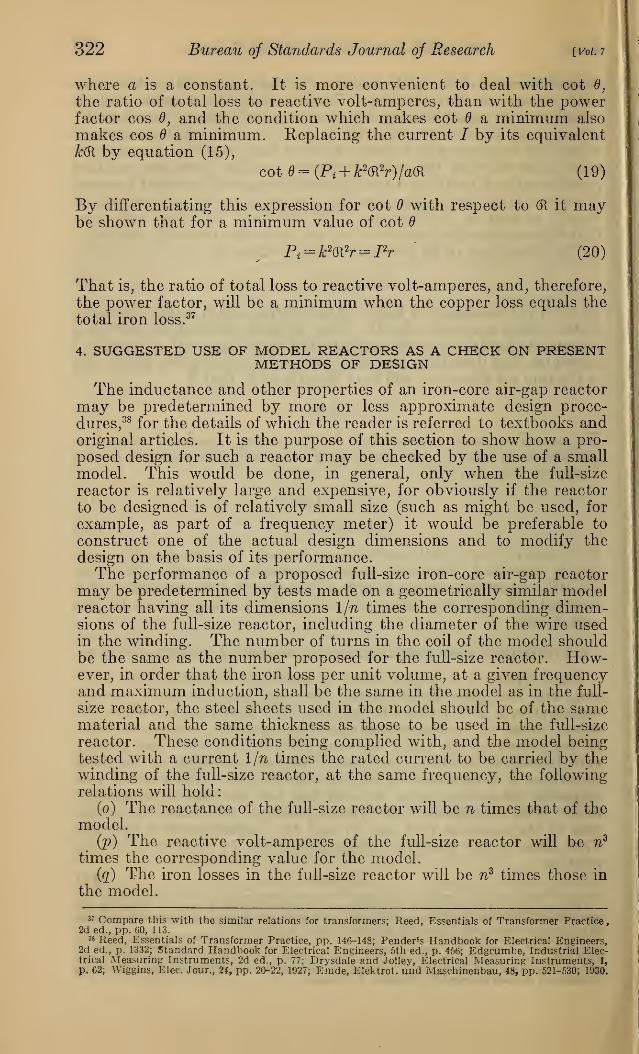
322 Bureau of Standards Journal of Research [Vol. ?
where a is a constant. It is more convenient to deal with cot 0,
the ratio of total loss to reactive volt-amperes, than with the powerfactor cos 0, and the condition which makes cot a minimum also
makes cos a minimum. Replacing the current / by its equivalentk(R by equation (15),
cot = (Pi + k2(R
2r)[a(R (19)
By differentiating this expression for cot with respect to (R it maybe shown that for a minimum value of cot
Pi = k2(R
2r = I2
r (20)
That is, the ratio of total loss to reactive volt-amperes, and, therefore,
the power factor, will be a minimum when the copper loss equals the
total iron loss.37
4. SUGGESTED USE OF MODEL REACTORS AS A CHECK ON PRESENTMETHODS OF DESIGN
The inductance and other properties of an iron-core air-gap reactor
may be predetermined by more or less approximate design proce-
dures, 38 for the details of which the reader is referred to textbooks andoriginal articles. It is the purpose of this section to show how a pro-
posed design for such a reactor may be checked by the use of a smallmodel. This would be done, in general, only when the full-size
reactor is relatively large and expensive, for obviously if the reactor
to be designed is of relatively small size (such as might be used, for
example, as part of a frequency meter) it would be preferable to
construct one of the actual design dimensions and to modify thedesign on the basis of its performance.The performance of a proposed full-size iron-core air-gap reactor
may be predetermined by tests made on a geometrically similar modelreactor having all its dimensions 1/n times the corresponding dimen-sions of the full-size reactor, including the diameter of the wire usedin the winding. The number of turns in the coil of the model shouldbe the same as the number proposed for the full-size reactor. How-ever, in order that the iron loss per unit volume, at a given frequencyand maximum induction, shall be the same in the model as in the full-
size reactor, the steel sheets used in the model should be of the samematerial and the same thickness as those to be used in the full-size
reactor. These conditions being complied with, and the model beingtested with a current 1/n times the rated current to be carried by thewinding of the full-size reactor, at the same frequency, the followingrelations will hold:
(o) The reactance of the full-size reactor will be n times that of themodel.
(p) The reactive volt-amperes of the full-size reactor will be n3
times the corresponding value for the model.
(q) The iron losses in the full-size reactor will be nz times those in
the model.
w Compare this with the similar relations for transformers; Reed, Essentials of Transformer Practice,2d ed., pp. 60, 113.
3» Reed, Essentials of Transformer Practice, pp. 146-148; Pendens Handbook for Electrical Engineers,2d ed., p. 1332; Standard Handbook for Electrical Engineers, 5th ed., p. 456; Edgcumbe, Industrial Elec-trical Measuring Instruments, 2d ed., p. 77; Drysdale and Jolley, Electrical Measuring Instruments, 1,
p. 62; Wiggins, Elec. Jour., 24, pp. 20-22, 1927; Emde, Elektrot. und Maschinenbau, 48, pp. 521-530; 1930.

Brooks] Standards of Inductance; Model Reactors 323
(r) The copper loss in the full-size reactor, when rated currentflows, will be n times the copper loss in the model.
It may be that the use on the model of a winding having the samenumber of turns as in the proposed full-size reactor will result in avalue of reactance in the model which is inconveniently low formeasurement. To take care of this difficulty, the model may bewound with p times the number of turns to be used in the full-size
reactor. The resulting value of reactance of the model must in this
case be multiplied by n/p2 to get the reactance of the full-size reactor.Similarly, if the cross-sectional area of the wire used in winding themodel is 1/pn2 times that of the wire to be used on the full-size reactor,
the resistance of the winding of the model must be multiplied byl/p2n to get the resistance of the full-size winding.The statement made above concerning the copper loss of the full-
size winding neglects the greater skin-effect resistance ratio in this
winding. It is obviously impracticable to test the model at a higherfrequency to take care of this matter, as can be done for a coil havingno iron core, because of the uncertainty as to the effect of this higherfrequency on the iron losses.
The fact that the copper loss of the full-size reactor is only n timesthat of the model while the value of reactive volt-amperes is n3 timesas great means that the small size of the model makes it inefficient
for the same reason that small transformers and small generators areinefficient. It implies also that to obtain the necessary data with themodel it will be necessary to overload its winding considerably. Thisis evident from the fact that the wire used in winding the model, withonly 1/n2 times the cross section of the wire to be used on the full-size
reactor, must carry 1/n times the current of the latter. The resulting
heating can be kept down, if necessary, by immersing the model inoil and by passing current through it only long enough to obtainreadings. The container for the oil should be such as not to affect
the performance of the model, either by altering the magnetic leakageflux or by providing a path for eddy currents.
It follows from relations (o) to (r), page 322, that the power factorof the full-size reactor will be lower than that of the model, and can bedetermined from these relations. After experiments have been madeon the model with various lengths of gap, values of reactance and of
power factor of the full-size reactor for the various corresponding gaplengths can be computed and plotted as a function of gap length in
order to find what gap length gives the required reactance, andwhat the corresponding value of power factor will be. These curveswill have the general form shown in Figure 10. In this figure it will
be noted that instead of power factor the ratio of watts loss (iron pluscopper) to reactive volt-amperes has been used. The latter ratio is
found by a simple division, while the power factor requires squaringthese two quantities, extracting the square root of their sum, anddividing the watts loss by the result. Much labor will be saved byusing cot 0, the ratio of watts to reactive volt-amperes, during thedesign process. It approximates more and more closely to the powerfactor cos as the latter approaches zero, as may be seen from thefollowing table, in which values of the ratio are rounded to the nearestunit in the third decimal place.

324 Bureau of Standards Journal of Research
Table 3
Ratio of Ratio of
Power watts loss Power watts loss
factor, to reactive factor, to reactivecos volt-am- cos 6 volt-am-
peres, cot peres, cot
0.000 0.000 0.120 0.121.010 .010 .140 .141.020 .020 .160 .162.030 .030 .180 .183.040 .040 .200 .204.050 .050 .250 .258
.060 .060 .300 .314
.070- .070 .350 .374
.080 .080 .400 .436
.090 .090 .450 .504
.100 .101 .500 .577
[Vol.7
Hi
E
Length of Air GapFigure 10.
—
Performance of an iron-core air-gap reactor as afunction of the
length of the air gap, with constant frequency, and with the current varied
to maintain a constant value of maximum magnetic flux density in the core
From the curve Leo of Figure 10 the gap length which will give
the required reactance can be ascertained, and also the correspondingvalue of the ratio of watts to reactive volt-amperes, which may betranslated into power factor with the aid of Table 3. Referring to
Figure 10, if the required value of reactance corresponds to the gaplength Oli, the ratio of watts to reactive volt-amperes will be greater
than the minimum value possible with a reactor of these core di-
mensions, which minimum value is had when the gap length is Ol2 .
This latter gap length, however, corresponds to a value of reactancelower than the required value. Hence if the ratio of watts to reactive
volt-amperes must be made lower the only remedy is to increase thedimensions of the proposed full-size reactor. A new set of curves is
to be plotted from the data already observed on the model, using asomewhat larger dimension ratio n2 in place of n. On the assumptionthat the rated current and the cross section of the conductor of the

Brooks] Standards of Inductance; Model Reactors 325
full-size reactor are to remain as originally planned, it is evidentthat the proposed larger full-size reactor will have a coil cross section
greater than that originally proposed by the factor (n2/n)2
, and thatthe number of turns will, therefore, be greater by this factor. Thevalues of reactance of the proposed larger reactor, for any givenrelative gap lengths, will be n2
5/n4: times the corresponding valuesalready observed for the model.39 Similarly, the reactive volt-amperesfor the proposed larger reactor, with (n2/n)
2 times the originally
proposed number of turns, will be n2Jn2 times the reactive volt-
amperes of the model, for corresponding relative gap lengths; theiron loss will be n2
3 times that in the model, and the copper loss
will be n2 fn2 times that in the model, for corresponding relative
gap lengths. These ratios may be derived from relations (o) to (r),
inclusive. P. 322.
The new curves will resemble the set relating to the first proposedfull-size reactor, but the required value of reactance (if n2 has notbeen chosen too much greater than n) will be associated with a valueof the ratio of watts to reactive volt-amperes lower than in the caseof the first proposed reactor. If n2 has been chosen too large, therequired value of reactance may correspond to an unduly large
relative length of air gap. This means a waste of material, at least,
and possibly with it a needlessly large value of the ratio of watts to
reactive volt-amperes. A smaller trial value of dimension ratio,
intermediate between n and n2) should be tried, and the processrepeated until a design is found in which the desired value of reactanceoccurs near the minimum value of the above ratio.
For very short relative lengths of gap the performance of themodel reactor may approximate too closely (for some purposes) to
that of an iron-core reactor without an air gap, in that the reactancewill vary too much with the current. For such purposes, only thosevalues of relative gap length should be considered for adoption for
which the reactance of the model is sufficiently independent of thevalue of the current to satisfy the requirements of the particular
application.
5. SUGGESTED USE OF MODEL REACTORS AS AN INDEPENDENTBASIS OF DESIGN
(a) UNCERTAINTY AS TO GAP RELUCTANCE, STRAY FLUX, ETC.
The uncertain elements in the methods of design now in use arise
from the fact that the magnetic flux flows in part through leakagepaths in a manner difficult to predetermine, and the flux across theair gap fringes out so that the cross section of the air-gap flux is
greater than that of the iron core. When the gap is very short in
comparison with the dimensions of the core perpendicular to theflux path, the reluctance of the gap will not differ greatly from thatcomputed on the assumption of no leakage and no fringing of flux
at the gap. As the relative length of the gap increases, the effects of
leakage and fringing increase and it becomes increasingly difficult
to predetermine the reluctance accurately. The use of models (or
of a single model, the length of its gap being varied by steps) has
8* If the number of turns on the larger proposed reactor had been left the same as the number originallyplanned, its reactance would have been simply «2 times the corresponding value for the model. Increasingthe number of turns by the factor («2/n) 2 increases the reactance by the further factor (nj/n)*, that is, toftjVw4 times that of the model.
64825—31 8

326 Bureau of Standards Journal of Research [Vol. r
the advantage that the manner of leaking of the flux and fringingat the gap will be the same in the model as in any larger reactorwhich is geometrically similar in all dimensions,40 including gaplength, provided the steel is worked at the same frequency and thesame maximum value of induction. It is therefore suggested thatthe designer may begin by experiments on a model of suitable form,tested at a suitable value of maximum induction, and from the results
compute the dimensions of a full-size reactor to have the desiredelectrical properties. The following general procedure is suggested:
(b) CHOICE OF FORM OF CORE AND LOCATION OF GAP
Various forms of core and locations of gap are used, and few generalrules can be given. For economy of manufacture form-wound coils
should be used if possible. From the standpoint of reducing leakageit is best to have the gap near the axial center of the. coil, but this is
not so convenient in some respects as are other arrangements wherethe gap is visible and accessible for measurement. The reader is
referred to text books 41 in which typical forms are shown and their
advantages and disadvantages discussed.
(c) CHOICE OF CORE MATERIAL AND MAXIMUM FLUX DENSITY
As previously stated, the material for the core is ordinarily silicon
steel sheets of the grade and thickness used in power and lighting
transformers (about 0.35 mm = 0.014 inch), and the maximum valueof induction is properly chosen at about the same value as used in
such transformers for the given frequency.
(d) EXPERIMENTS TO BE MADE WITH THE MODEL
Two windings should be used—one of relatively fine wire which doesnot surround the air gap and the regular winding which may or
may not do so. The fine-wire winding is intended for use as a test
coif to indicate when the flux in the iron has its desired value. Thevoltage E in volts induced in it when current flows in the regular
winding is to be measured 42 and from it and the number of turns Nin the test coil, the frequency/ and the net cross-sectional area Acm of
the iron core in cm2, the maximum magnetic induction in the core,
BmSiX , in maxwells per cm2, should be found by using the ordinary
transformer equation
#=4.44 Nf BmxAem X10"8(21)
from which
10»E^max ~4.44iVy>UKZZ)
Some American designers, while expressing Z?max in maxwells per
cm2,prefer to express the net cross-sectional area of the core in square
«° Except the thickness of the sheet steel, which, as previously suggested, should be the same in the modeland in the full-size reactor.« Drysdale and Jolley, Electrical Measuring Instruments, Pt. I, p. 65; Keinath, Die Technik der elek-
trischen Messgerate, 3d ed., 1, pp. 467-470.«> If an a. c. potentiometer is available to measure this voltage, no correction for the resistance of the test
coil is necessary. If it is necessary to use an a. c. voltmeter to measure the voltage induced in the test coil,
the voltmeter should preferably have a relatively high resistance. If R, is the resistance of the voltmeter
and Re that of the test coil, the voltmeter reading should be multiplied by (R,+Re)/R, to obtain the inducedvoltage.
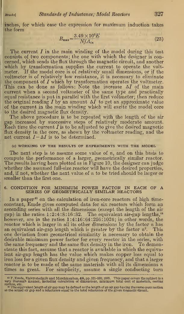
Brooks] Standards of Inductance; Model Reactors 327
inches, for which case the expression for maximum induction takesthe form
^ 3.49X10^
The current / in the main winding of the model during this test
consists of two components; the one with which the designer is con-cerned, which sends the flux through the magnetic circuit, and anotherwhich by transformation supplies the current to operate the volt-
meter. If the model core is of relatively small dimensions, or if thevoltmeter is of relatively low resistance, it is necessary to eliminatethe component of / which by transformation operates the voltmeter.This can be done as follows: Note the increase Al of the maincurrent when a second voltmeter of the same type and practically
equal resistance is put in parallel with the first voltmeter; then reducethe original reading / by an amount Al to get an approximate valueof the current in the main winding which will excite the model coreto the desired magnetic flux density.
The above procedure is to be repeated with the length of the air
gap increased by successive steps of relatively moderate amount.Each time the current /is to be adjusted to give the desired magneticflux density in the core, as shown by the voltmeter reading, and thenet current I—AI is to be determined.
(e) WORKING UP THE RESULTS OF EXPERIMENTS WITH THE MODEL
The next step is to assume some value of n, and on this basis to
compute the performance of a larger, geometrically similar reactor.
The results having been plotted as in Figure 10, the designer can judgewhether the assumed full-size reactor will have the desired properties,
and, if not, whether the next value of n to be tried should be larger orsmaller than the first one.
6. CONDITION FOR MINIMUM POWER FACTOR IN EACH OF ASERIES OF GEOMETRICALLY SIMILAR REACTORS
In a paper 43 on the calculation of iron-core reactors of high time-constant, Emde gives computed data for six reactors which form anascending series with all the dimensions (except the length of the air
gap) in the ratios 1:2:4:8:16:32. The equivalent air-gap lengths,44
however, are in the ratios 1:4:16:64:256:1024; in other words, thereactor which is larger in all its other dimensions by the factor n hasan equivalent air-gap length which is greater by the factor n2
. Thisone deviation from geometrical similarity is necessary to obtain thedesirable minimum power factor for every reactor in the series, withthe same frequency and the same flux density in the iron. To demon-strate this fact, assume that a reactor is available in which the equiva-lent air-gap length has the value which makes copper loss equal to
iron loss for a given flux density and given frequency, and that a larger
reactor is to be made of the same materials with all its dimensions ntimes as great. For simplicity, assume a single conducting turn
43 F . Emde, Elektrotechnik und Maschinenbau, 48, pp . 521-530; 1930. This paper covers the subject in avery thorough manner, including calculation of dimensions, minimum total cost of materials, coolingsurface, etc.
** The equivalent length of air gap may be defined as the length of an air gap having the same cross sectionas the actual air gap and a reluctance equal to the total reluctance of the given magnetic circuit.

328 Bureau of Standards Journal of Research [vol. 7
around the core in each reactor. With the same density of current in
the copper and the same magnetic flux density in the core the copperlosses and the iron losses of the second reactor will each be n3 timesthe corresponding quantities for the first reactor. As shown above(p. 322), equality of these two losses is necessary to obtain the minimumpower factor; therefore, the current in the second reactor is definitely
fixed as n2 times that in the first reactor. It remains to determinewhat length of air gap in the second reactor is compatible with this
required current.
The cross section of the magnetic circuit in the larger reactor is
n2 times that of the smaller reactor, and the condition of equal flux
density implies that the total flux in the second reactor is n2 timesthat in the first. The setting up of n2 times the flux by n2 times the
current means that the total reluctance is the same in both reactors,
and this in turn means that the larger reactor with n2 times the area
of flux path must have an equivalent air-gap length n2 times that of
the smaller reactor.
The relatively greater equivalent length of gap in the larger reactor,
with the same value of magnetic energy density, makes the ratio of
total magnetic energy to total losses n times as great in the larger
reactor. This is equivalent to saying that cot for the secondreactor (which is very nearly the same as the power factor cos 0) is
l/n times the value of cot for the smaller reactor. Emde's table of
data for his computed series of reactors includes values of time-con-stant and of cot 0. The ratio of mean length of flux path in iron to
the equivalent air-gap length for the series decreases as l/n from the
value 546 in the smallest reactor to 17 in the largest. Emde points
out that one would usually have to discard as useless the two reactors
at the lower end of his series because the air gaps are so short in com-parison with the length of the flux path in iron that the curvature of
the magnetization line is too great. For small values of time con-
stant it may therefore be advantageous to use an air-core reactor.
VI. ACKNOWLEDGMENT
The writer is greatly indebted to Dr. Frederick W. Grover for his
careful reading of the manuscript, for many constructive suggestions
for its improvement, for checking the correctness of the similitude
relations concerning reactors (pp. 296, 297, 322, and 323), and for thecomputation of the data given in Table 1.
Washington, May 12, 1931.