design of prestressed concrete pile … journal/1974/sept-oct... · design of prestressed concrete...
TRANSCRIPT
DESIGN OF PRESTRESSEDCONCRETE PILEFOUNDATIONSGeorge C. FotinosChief EngineerSanta Fe-Pomeroy, Inc.Engineering and Construction Subsidiary
of Santa Fe International CorporationPetaluma, California
This sixth paper in the series of articleson "Design Considerations for a PrecastPrestressed Apartment Building" coversthe design of the prestressed concretepile foundations.
The first part of the paper describesthe typical design considerations thatenter into proper pile selection. Suchfactors as pile capacities, pile lengths,driving conditions, and pile prices arediscussed.
The second part of the paper pre-sents the detailed design calculationsfor a typical prestressed pile founda-tion.
Detailed computations are given for
an interior footing, a perimeter wallfooting, and a footing at transfer beam.
Step-by-step calculations are includ-ed for finding the number of piles, pilelayout, beam shear, punching shear,moment steel, development length, andsteel distribution. A middle section isdevoted to lateral load analysis.
Finally, the last section presents thepile dowel and pile prestress calcula-tions including a method for finding thepile pickup points.
A detailed foundation plan of thebuilding, including sections, is includedat the end of the design computations.
DESIGN CONSIDERATIONS
General
The design of a building foundationis affected by several factors. For pur-poses of designing the foundation forthis building, certain assumptions havebeen made relating to site conditionsand economic considerations.
Design loads
As a starting point we will use thedesign loads from the lateral load analy-sis presented earlier by John V. Chris-tiansen in "Analysis of Lateral Load Re-sisting Elements" (see Paper 2 in thisseries).
Table 1 shows a summary of thedesign loads that will be used in de-veloping the foundation design.
40
Note that wind, and not seismic ef-fects, controls the design of the struc-ture.
SITE CONDITIONS
In order to select the proper size pre-stressed concrete pile to use in thefoundation, it is necessary to determineestimated pile lengths and maximumpile loads that can be developed by thesoil.
In many instances, the maximum pileload is limited by the soil conditionsrather than the structural pile capacity.For example, a dense sand layer under-lain by clay may offer sufficient bearingfor moderate pile loads while not beingable to support the full structural loadthat the pile may be able to offer.
A soil exploration program should beincluded in the foundation design. Suf-ficient borings should be taken to in-sure that the subsurface conditions canbe accurately established. In additionto providing data for developing pilecapacities, the soil study normally in-cludes an investigation of estimatedsettlements. Length of piling is oftencontrolled by settlement requirementsrather than bearing capacity.
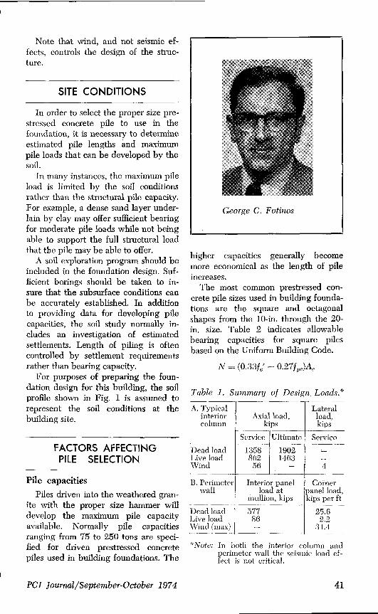
For purposes of preparing the foun-dation design for this building, the soilprofile shown in Fig. 1 is assumed torepresent the soil conditions at thebuilding site.
George C. Fotinos
higher capacities generally becomemore economical as the length of pileincreases.
The most common prestressed con-crete pile sizes used in building founda-tions are the square and octagonalshapes from the 10-in, through the 20-in. size. Table 2 indicates allowablebearing capacities for square pilesbased on the Uniform Building Code.
N = (0.33f0' — 0.27f,,)A,
Table 1. Summary of Design Loads.°
A. Typical Lateral
interior Axial load, load,
column kips kips
Service (Ultimate I ServiceFACTORS AFFECTINGPILE SELECTION
Pile capacities
Piles driven into the weathered gran-ite with the proper size hammer willdevelop the maximum pile capacityavailable. Normally pile capacitiesranging from 75 to 250 tons are speci-fied for driven prestressed concretepiles used in building foundations. The
Dead load 1358 I 1902. ILive load 862 1463Wind 56 4
B. Perimeter. Interior panel Cornerwall j load at panel load,
mullion, kips kips per ftDead load 577 25.6Live load 86 2.2Wind (max) — 34.4
°Note: In both the interior column andperimeter wall the seismic load ef-fect is not critical.
PCI Journal/September-October 1974 41
120
100TOP SOI
80
ZO_I-Q
WJW 60
Q LLW
Q 40
CLAY
SOFT WEATHERED GRANITE
BED ROCK
Fig. 1. Assumed soil conditions.
20
0
The effective prestress in Table 2 isassumed to be 750 psi. Concretestrength was entered at 6000 psi in 28days.
Fig. 2 represents a typical bearingcapacity curve which would be devel-
Table 2. Bearing Capacityfor Various Pile Sizes.
Pile size Bearing(square) capacity,
in. tons
10 8712 12614 17216 22518 28620 353
oped upon completion of the soil ex-ploration program.
For this particular problem it hasbeen assumed that a gradual increasein bearing capacity is available withdepth until the pile reaches the weath-ered granite at which point high bear-ing capacity is available for small addi-tional penetration.
Pile lengthsMaximum economy can be achieved
in the use of prestressed concrete pilesif piles can be driven full length with-out field splices. While splices can beinstalled in the pile to facilitate han-dling, their use will normally increasethe pile cost.
42

PILE CAPACITY - TONS120 160 200 240 280 3200 40 80
20
LAWWlL
Z 40O
IY
WZ GW O0
ATHERaD GRANIT
80
BEDRDC
Fig. 2. Assumed pile capacity curve (16-in. prestressed concrete pile).
Table 3 indicates practical lengths tobe used in selecting pile sizes. Theselengths are controlled by the transpor-tation and handling of full length pil-ing.
Piles longer than those shown abovemay be used under certain conditions.Extra long piles may require additionalprestress in the pile for handling pur-poses.
Since the pile capacity curve indi-cates pile lengths will be in the 80 to90-ft range, any of the piles notedabove would be satisfactory in meetingthe practical length for handling piles.
Driving conditions
If hard driving is anticipated at thesite, the prestressed pile is sometimesfitted with a steel tip to enable the pileto penetrate the dense material a mini-mum distance for uplift or other con-siderations. This tip usually consists of abearing pile section cast into the lower
section of the pile. Since the end areais substantially less than the prestressedpile, the resistance due to end bearingis reduced thus allowing the pile toreach required elevations.
Use of the wave equation method ofpredicting driving resistance andstresses will assist the designer inpredicting the driving behavior of theproposed pile. This analysis, which con-siders the elastic behavior of the pileduring driving has proven to be a use-ful and reliable aid to both engineers
Table 3. Length of Pilingfor Various Pile Sizes.
Pile size Length,(square), in. ft
10 10012 11014 12016 15018 17020 190
PCI Journal/September-October 1974 43
8
7
6
5
Z FJ Oa. 0 4lLO ¢
~ J00 3O
2
010 12 14 16 18 20
PILE SIZEINCHES
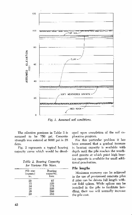
Fig. 3. Cost of piling in relation to pile size.
and contractors in selecting proper sizepile hammers that will insure the pile isdriven efficiently and without damage.
For further details of this methodsee E. A. L. Smith, "Pile-Driving Anal-ysis by the Wave Equation," Transac-tions—ASCE, 3306, Vol. 127, 1962, pp.1145-1193.
Pile pricesProbably the most important factors
influencing the selection of prestressed
pile are pile prices and availability.When designing a foundation a reviewof current unit prices for prestressedpiles available in the area should bemade before selection is made.
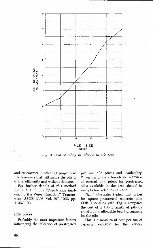
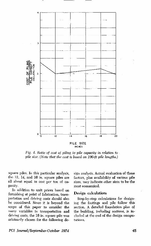
Fig. 3 illustrates typical unit pricesfor square prestressed concrete pilesFOB fabrication yard. Fig. 4 comparesthe cost of a 100-ft length of pile di-vided by the allowable bearing capacityfor the pile.
This is a measure of cost per ton ofcapacity available for the various
44
3
V' }ZUo
aa:NU- 2J
WJ0)-i0on.0
01 '
10 12 14 16 I8 20
PILE SIZEINCHES
Fig. 4. Ratio of cost of piling to pile capacity in relation topile size. (Note that the cost is based on 100-ft pile lengths.)
square piles. In this particular analysis,the 12, 14, and 16 in. square piles areall about equal to cost per ton of ca-pacity.
In addition to unit prices based onfurnishing at point of fabrication, trans-portation and driving costs should alsobe considered. Since it is beyond thescope of this paper to consider themany variables in transportation anddriving costs, the 16 in. square pile wasarbitrarily chosen for the following de-
sign analysis. Actual evaluation of thesefactors, plus availability of various pilesizes, may indicate other sizes to be themost economical.
Design calculationsStep-by-step calculations for design-
ing the footings and pile follow thissection. A detailed foundation plan ofthe building, including sections, is in-cluded at the end of the design compu-tations.
PCI Journal/September-October 1974 '45
FOUNDATION DESIGN CALCULATIONS
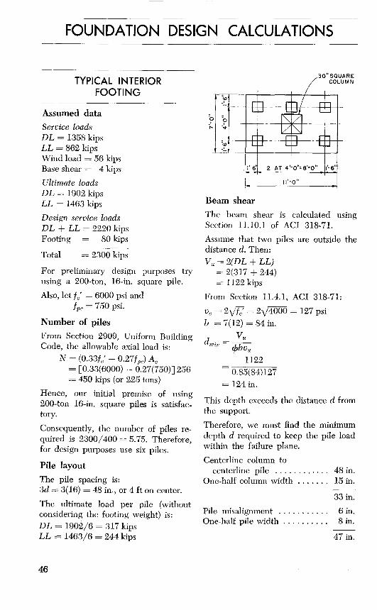
TYPICAL INTERIORFOOTING
Assumed dataService loadsDL = 1358 kipsLL = 862 kipsWind load = 56 kipsBase shear = 4 kipsUltimate loadsDL = 1902 kipsLL = 1463 kips
Design service loadsDL ± LL = 2220 kipsFooting = 80 kips
Total = 2300 kips
For preliminary design purposes tryusing a 200-ton, 16-in, square pile.
Also, let f0' = 6000 psi andf, = 750 psi.
Number of pilesFrom Section 2909, Uniform BuildingCode, the allowable axial load is:
N=(0.33f0; —0.27fo„)A,= [0.33(6000) — 0.27(750)] 256= 450 kips (or 225 tons)
Hence, our initial premise of using200-ton 16-in, square piles is satisfac-tory.
Consequently, the number of piles re-quired is 2300/400 = 5.75. Therefore,for design purposes use six piles.
Pile layout
The pile spacing is:3d = 3(16) = 48 in., or 4 ft on center.
The ultimate load per pile (withoutconsidering the footing weight) is:DL = 1902/6 = 317 kipsLL = 1463/6 = 244 kips
30' SQUARECOLUMN
ti
. I^-6^ 2 AT 4^-O"=8'-0° ^6-
11.-0„
Beam shear
The beam shear is calculated usingSection 11.10.1 of ACI 318-71.Assume that two piles are outside thedistance d. Then:V,, = 2(DL + LL)
= 2(317 + 244)= 1122 kips
From Section 11.4.1, ACI 318-71:v0 = 2\/f(,' = 2V4000 = 127 psib = 7(12)=84 in.
^udmin = ybvu
J 11220.85(84)127
= 124 in.
This depth exceeds the distance d fromthe support.
Therefore, we must find the minimumdepth d required to keep the pile loadwithin the failure plane.
Centerline column tocenterline pile ............ 48 in.
One-half column width ....... 15 in.
33 in.
Pile misalignment ........... 6 in.One-half pile width ........... 8 in.
47 in.
46
Therefore, the minimum depth d forbeam shear is 47 in. For design pur-poses use drain, = 48 in.
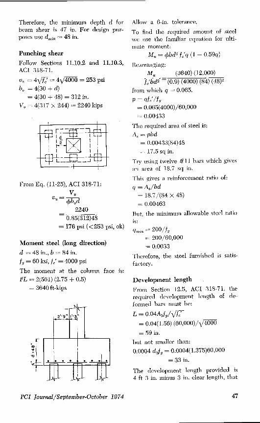
Punching shear
Follow Sections 11.10.2 and 11.10.3,ACI 318-71.
v,, = 4\/f, = 4\/4000 = 253 psibn = 4(30 + d)
= 4(30 + 48) = 312 in.V,, = 4(317 x 244) = 2240 kips
r r r LL I d L J I L J
1 2 I
L 11 J41L J L. _J L J
From Eq. (11-25), ACI 318-71:Vu
v ` obod
_ 22400.85(312)48
= 176 psi (<253 psi, ok)
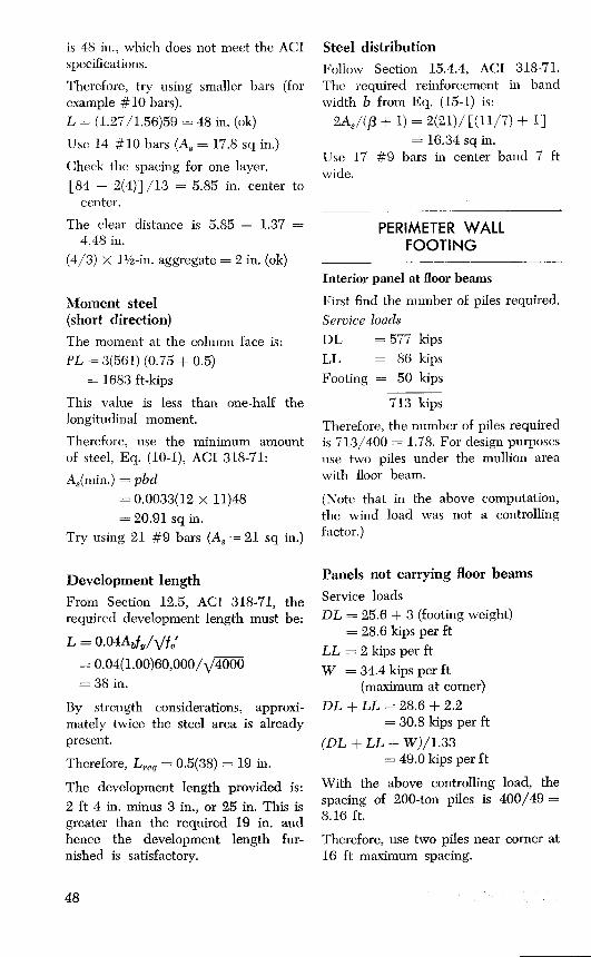
Moment steel (long direction)
d = 48 in., b = 84 in.f^ = 60 ksi, f, = 4000 psi
The moment at the column face is:PL = 2(561) (2.75 + 0.5)
= 3640 ft-kips
Allow a 6-in. tolerance.
To find the required amount of steelwe use the familiar equation for ulti-mate moment:
M,n = 4bd2 f/ q (1 — 0.59q)
Rearranging:Mu (3640) (12,000)
f, bd2 — (0.9) (4000) (84) (48)2from which q = 0.065.
p=qf//f,,= 0.065(4000)/60,000= 0.00433
The required area of steel is:A,, = pbd
= 0.00433(84)48= 17.5 sq in.
Try using twelve #11 bars which givesan area of 18.7 sq in.
This gives a reinforcement ratio of:q = A,,/bd
= 18.7/(84 x 48)= 0.00463
But, the minimum allowable steel ratiois:
q'min = 200/fv= 200/60,000= 0.0033
Therefore, the steel furnished is satis-factory.
Development lengthFrom Section 12.5, ACI 318-71, therequired development length of de-formed bars must be:
L = 0.04Abfy/1./f,= 0.04(1.56) (60,000)/V4000
= 59 in.
but not smaller than:
0.0004 dvf„ = 0.0004(1.375)60,000
= 33 in.
The development length provided is4 ft 3 in. minus 3 in. clear length, that
PCI Journal/September-October 1974 47
is 48 in., which does not meet the ACIspecifications.
Therefore, try using smaller bars (forexample #10 bars).L = (1.27/1.56)59 = 48 in. (ok)
Use 14 # 10 bars (A 3 = 17.8 sq in.)
Check the spacing for one layer.[84 — 2(4)] /13 = 5.85 in. center to
center.
The clear distance is 5.85 — 1.37 =4.48 in.
(4/3) X 1 1/z-in. aggregate = 2 in. (ok)
Moment steel(short direction)
The moment at the column face is:PL = 3(561) (0.75 + 0.5)
= 1683 ft-kips
This value is less than one-half thelongitudinal moment.
Therefore, use the minimum amountof steel, Eq. (10-1), ACI 318-71:
AS(min.) = pbd
= 0.0033(12 x 11)48= 20.91 sq in.
Try using 21 #9 bars (A 3 = 21 sq in.)
Development length
From Section 12.5, ACI 318-71, therequired development length must be:
L = 0.04AbfY/Vfc'= 0.04(1.00)60,000/x4000= 38 in.
By strength considerations, approxi-mately twice the steel area is alreadypresent.
Therefore, L,eq = 0.5(38) = 19 in.
The development length provided is:2 ft 4 in. minus 3 in., or 25 in. This isgreater than the required 19 in. andhence the development length fur-nished is satisfactory.
Steel distribution
Follow Section 15.4.4, ACI 318-71.The required reinforcement in bandwidth b from Eq. (15-1) is:
2A3 /(j3 + 1) = 2(21)/ [( 11/7) + 1]= 16.34 sq in.
Use 17 #9 bars in center band 7 ftwide.
PERIMETER WALLFOOTING
Interior panel at floor beams
First find the number of piles required.Service loadsDL =577 kipsLL = 86 kipsFooting = 50 kips
713 kips
Therefore, the number of piles requiredis 713/400 = 1.78. For design purposesuse two piles under the mullion areawith floor beam.
(Note that in the above computation,the wind load was not a controllingfactor.)
Panels not carrying floor beams
Service loadsDL = 25.6 + 3 (footing weight)
= 28.6 kips per ftLL = 2 kips per ftW = 34.4 kips per ft
(maximum at corner)DL + LL = 28.6 + 2.2
= 30.8 kips per ft
(DL + LL + W)/1.33= 49.0 kips per ft
With the above controlling load, thespacing of 200-ton piles is 400/49 =8.16 ft.
Therefore, use two piles near corner at16 ft maximum spacing.
48

FOOTING ATTRANSFER BEAM
The added load to column at transferbeam is equal to one full panel (12 ft)loading.
DL = 25.6 kips per ftLL = 2.2 kips per ft
2"i.2i kips per It
Total load = 27.8 X 12 = 334 kips
Transfer girder = 15 kips
Total load to foundation349 + 577 + 86 = 1012 kipsFooting = 50 kips
1062 kips
Therefore, the number of piles requiredis 1062/400 = 2.65. That is, for designpurposes use four piles.
LATERAL LOADANALYSIS
Wall shear (transverse), V = 369 kips
Number of piles in wall, N = 14V/N = 369/14 = 26.4 kips
Minimum vertical load at corner:1075 — 668 = 407 kips
Assume this load is distributed to sixpiles. Therefore, the load per pile is407/6 = 68 kips per pile
Maximum vertical load at interiorpanel:
713/2 = 356 kips per pile
The maximum moment in the pile isdetermined from the interaction of thepile with the soil.
The following are two suggested refer-ences:1. Broms, B. B., "Design of Laterally
Loaded Piles," Journal of Soil Me-chanics and Foundations, ASCE,May 1965.
2. Reese, L. C., and Matlock, H.,"Non-Dimensional Solutions for Lat-erally Loaded Piles," Bureau of En-gineering Research No. 29, Univers-ity of Texas, September 1956.
For purposes of this design assume themaximum in the pile to be 75 ft-kips.
Minimum conditionP = 68 kips, M = 75 ft-kips
The pile stresses are calculated from:f = P/A + Pe/Z ± M/Z
= (68/254) + 0.750 ± 75(12)/668= —2365 psi (comp) and
+329 psi (tens)
Now, since the allowable f, is:0.45(6000)1.33 = 3600 psi
the section is satisfactory in compres-sion. Also, because the allowable ten-sile stress is 600 psi, the computed ten-sile stress is below the required limit.
Maximum conditionP = 356 kips, M = 75 ft-kipsSimilarly, the pile stresses are com-puted as above:f = 356/254 + 0.750 ± 75(12)/668
= —3499 psi (comp) and—805 psi (comp)
As shown above, these stresses arewithin the allowable stress limits.
Check the interaction formula:
fa/F''a + fn/Fb < 1.33
From the Uniform Building Code:Fa =0.33 f,' —0.27 fp,
= 0.33(6000) — 0.27(750)= 1778 psi
F,, =0.45f,'= 0.45(6000)= 2700 psi
Therefore, applying the above formula:(1402/1778) + (1347/2700) = 1.287which is less than 1.33 (ok).
PCI Journal/September-October 1974 49
Note: The passive pressure of the soilon the footing in the vicinity of thetransverse wall could also be used toresist lateral load.
Pile dowels
Use the minimum amount of dowels inthe footing (i.e., 1 1/2 percent the pilearea).0.015(254) = 3.81 sq in.Use four #9 bars.
From previous calculations, the devel-opment length is 38 in.
To allow for a reduced prestress at thepile end use a 3 ft 6 in. embedment.
Use a standard hook on top of the bar.
From Section 12.8, ACI 318-71, the re-quired tensile stress in the bar is:
fh = l^f^= 540-\/4000= 34,152 psi
The minimum embedment length is:38(60 — 34)/60 = 16 in.
Pile prestress
From Section 2909, Uniform BuildingCode, the effective minimum prestressfor piles greater than 50 ft in length is700 psi.
For design purposes, including han-dling and driving resistance use a mini-mum prestress of 750 psi. Then theeffective prestress force is:
Pe = (0.750) (254) = 191 kips
The design prestress force is computedfrom:
1/z-in, diameter strand(70 percent ultimate) ... 28.91 kips
Losses (35,000 psi) ....... 5.36 kips
Designforce ............ 23.55 kips
Therefore, the required number ofstrands is 191/23.55 = 8.1.
For design purposes use nine 1/2-in. di-ameter strands.
The average compressive force then is:f, = 9(23.55)/254 = 835 psi
With reference to Section 2909, Uni-form Building Code, use a #5 gagespiral.
Top and bottom ..... 5 turns at 1 in.Bottom and top
(one-third) ........ at 3 in. pitch.Middle of pile ....... at 6 in. pitch.
The head of the pile should also bechecked for stresses using conventionalcolumn design since prestress is notpresent at the pile head. In general,this check is not a critical part of thedesign procedure.
Pickup points
f ^, = 835 psi
Use 50 percent impact with no tension.
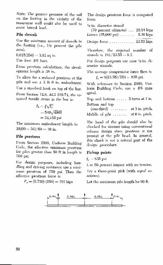
Try a three-point pick (with equal re-actions).
Let the maximum pile length be 90 ft.
0.14E 0.36E 0.36E 0.14L
50
The maximum moment is calculatedfrom:
(0.0095) (w) (L)2 (1.5)_ (0.0095) (0.273) (90) 2 (1.5)= 31.5 ft-kips
The stress is found from:
f =M/Z_ (31.5) (12)/668= 565 psi (<835 psi, ok)
The allowable maximum length is com-puted from:
L= M(0.0095) (w) (1.50)
(0.835)) ((668)
_ (0.0095) (0.273) (1.50) (12)
= 109 ft
Therefore, the selected length is sat-isfactory.
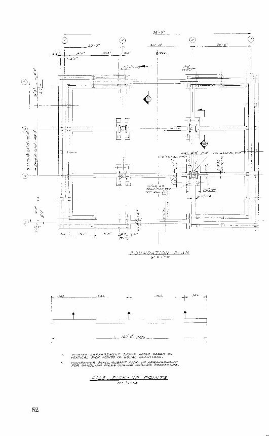
A detailed foundation plan of the building,including elevation and cross sections, aswell as the pile elevation and pile pickuparrangement, is given on the following
two pages.
Discussion of this paper is invited.Please forward your discussion to PCI Headquartersby February 1, 1975, to permit publication in theMarch-April 1975 PCI JOURNAL.
PCI Journal/September-October 1974 51
3S 0"
ISO Ca rr COSY M.
i n ^Zrorr II /-5 (TYF / 3,rI
OI
AcO
^ N
Hi___ __j r-__ CCL. BASE PL.TYP '
2 -G ESQ COL TP, {I
^ t/6r54PLS.CONC P/L TYP ^ ^ T_O'; TYP,EEE oEr / ^r ^I I
f ^^
I _I I
ti
Co" \ 13=3 ° 13S ^4 o
FOUNDAT/ON PLAN
./4L .36L _- 361. ./4L
i I
/. PICKING ARRANGEMENT SHOWN ABOVE BASED ONVEST/CAL P/C/C POINTS OP EQUAL REACTIONS.
2. CONTRACTOR SHALL -USOT/T P/C/C- UP ARRANGEMENTFOR NANOL/NG PILES OUR/NS OS/V/NO PROCEOURE-
/E P/C/<- UP POINTSNO SCALE
52
Io
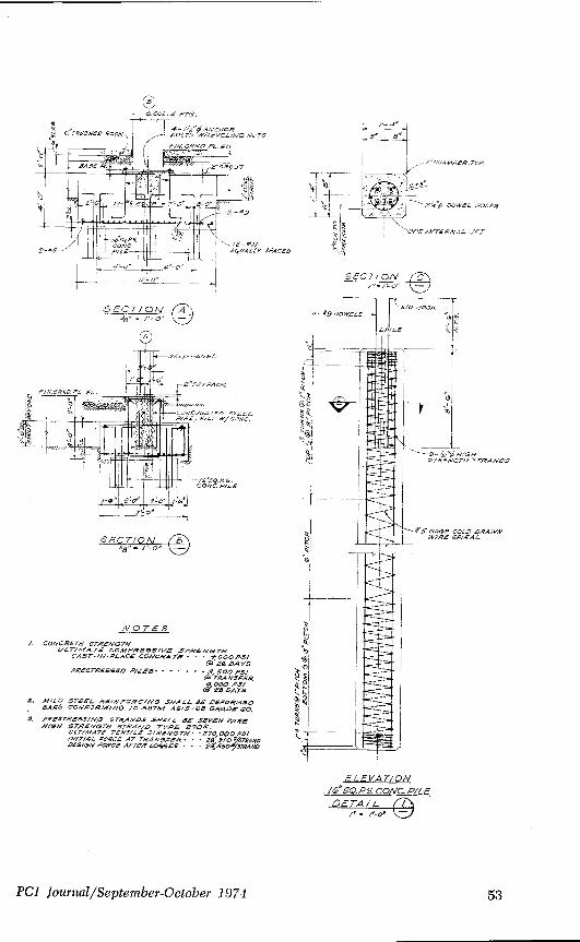
NOTES/. CONCRETE STRENG7H
LILT/MATE COMPRESS/VS STRENGTHCAST-/N-PLACE CONCRETE- - • 4, OOO PS/
@58 DAYSPRESTRESSED P/LEE • • - • - • - 3 500 PS/
@ TRANSFER600055/
G•'^ 2B 5475
2. MILD STEEL RE/NFORC/NG SNALL SE DEFORMEDEARS CONFORM/PG TO A57/N SON GRADE 60.
3, PRESTRESS//VG STRANDS SHALL SE SEVEN "V/REN/BH STRENGTH STRAND TYPE 270k.
ULT/MATE TENSILE STRENGTH • • 270,000 P5//WIT/AL FORCE AT TRANSFER .26 S/O STRAND025/54/FORCE AFTER LOSSES 23S50 /STR4RD
SECT/ON A
SECT/^
S
1-/dCHAMFER^TYG
OOWEL HOLES
'CPT /NTERNAL ,/ETz e
SPACES
SECT/ON C
ELEVATIONl"SQ.P5 CONC. PILEDETAIL t
/' /.-o.
PCI Journal/September-October 1974 53