design of penta-band omnidirectional slot antenna with slender columnar structure
TRANSCRIPT

594 IEEE TRANSACTIONS ON ANTENNAS AND PROPAGATION, VOL. 62, NO. 2, FEBRUARY 2014
Design of Penta-Band Omnidirectional Slot AntennaWith Slender Columnar Structure
Yue Li, Member, IEEE, Zhijun Zhang, Senior Member, IEEE, Zhenghe Feng, Fellow, IEEE, andMagdy F. Iskander, Life Fellow, IEEE
Abstract—In this paper, we have proposed a co-located andfolded slots antenna for multiband applications. The proposedantenna consists of three radiating slots, arranged on a compactsquare columnar structure. By properly tuning the dimensionsand the positions of the co-located slots, the proposed antennaoperates in penta-band, including DCS, PCS, UMTS, 2.5-GHz,and 3.5-GHz WiMAX bands. Additionally, omnidirectional ra-diation patterns are provided in the azimuthal plane for all theoperating bands. The overall volume of the proposed squarecolumnar antenna is only 50 10 10 mm , which is suited forvolume-limited systems. A prototype of the proposed antenna isfabricated and tested, to validate the design idea. The measureddata, including S parameter, radiation pattern, and gain, agreewell with the simulation results.
Index Terms—Antenna radiation patterns, multifrequency an-tenna, slot antennas.
I. INTRODUCTION
A NTENNA designs with multiple operating bands andomnidirectional radiation patterns are widely studied and
adopted in modern wireless communication system, especiallyfor the portable base stations and access points. By using themultiband antennas, more wireless services can be integratedto a single system. And the omnidirectional radiation patternsin the azimuthal plane are also in demand for the large areacoverage. Due to these reasons, numerous antenna researchersand engineers are working on this topic.In recent publications, different antenna design methods are
adopted to achieve omnidirectional radiation patterns in themultiple operating bands. First, the monopole antenna with aground is an acceptable candidate [1]–[10], with the intrinsic
Manuscript received June 14, 2013; revised August 26, 2013; acceptedNovember 13, 2013. Date of publication November 25, 2013; date of currentversion January 30, 2014. This work was supported by the National BasicResearch Program of China under Contract 2013CB329002, in part by theNational High Technology Research and Development Program of China (863Program) under Contract 2011AA010202, in part by the National NaturalScience Foundation of China under Contract 61301001, in part by the NationalScience and Technology Major Project of the Ministry of Science and Tech-nology of China 2013ZX03003008-002, and in part by the China PostdoctoralScience Foundation funded project 2013M530046.Y. Li, Z. Zhang, and Z. Feng are with State Key Laboratory on Microwave
and Digital Communications, Tsinghua National Laboratory for InformationScience and Technology, Department of Electronic Engineering, Tsinghua Uni-versity, Beijing, 100084, China (e-mail: [email protected]).M. F. Iskander is with HCAC, University of Hawaii at Manoa, Honolulu, HI
96822 USA (e-mail: [email protected]).Color versions of one or more of the figures in this paper are available online
at http://ieeexplore.ieee.org.Digital Object Identifier 10.1109/TAP.2013.2292517
omnidirectional radiation pattern in the azimuthal plane. Mul-tiple bands can be achieved by adopting multiple brancheswith different electrical lengths [1], [2], and parasitical loading[3]–[5] tuning the basic and higher modes. The ultra-wideband (UWB) concept is also used on monopole for multibandcoverage, with 2-D [6], [7] or 3-D [8]–[10] structures. Second,we can use dipoles with two symmetrical arms to generatethe azimuthal omnidirectional radiation patterns [11]–[14].Due to the symmetrical structures, the dipoles are feasible tobe arranged as array to achieve higher gain in the azimuthalplane [14]. Metamaterial is the third method to achieve omni-directional patterns for multiple bands application. Periodicallyarranged metallic posts are adopted to build an omnidirectionalradiated mode in [15], [16]. Left-handed loadings are integratedwith the loops in [17] and the monopoles in [18]. However,the impedance bandwidth of the metamaterial based omni-directional antenna is needed to be enhanced. Besides thesethree methods, other feasible designs are also used to achievethe azimuthal omnidirectional radiation patterns [19]–[22].For example, a dual-band series-fed antenna using continuoustransverse stub (CTS) technology is well designed and fab-ricated in [19]. In the [20], a dual-band Alford loop antennais designed to achieve horizontally polarized omnidirectionalradiation pattern. We also can employ several directional an-tennas to form the omnidirectional radiation pattern, such asback-to-back arranged Yagi antennas [21] and slot antennas[22]. However, this design strategy makes the overall antennavolume large.For the volume-limited systems, such as the portable base
stations and access points, 3-D structured antenna with com-pact dimension is preferred more. Compared with planar 2-Dstructure, 3-D structured antennas have smaller aspect ratio andmore compact volume. In the published literatures, widebandmonopoles can be folded to 3-D columnar structure for antennaminiaturization [8]–[10]. A planar ground is needed as theother pole for the monopole type antenna. However, in somecircumstances, small-volume equipment cannot provide suchlarge planar grounds. For this reason, other types of antennaswithout extra ground are required.In this paper, a penta-band omnidirectional radiated antenna
without extra ground is proposed. This antenna consists of threefolded slots, which are arranged on a square columnar structure.Omnidirectional radiation patterns are achieved in penta-band,including the digital cellular system (DCS: 1.71–1.88 GHz),the personal communication system (PCS: 1.85–1.99 GHz), theuniversal mobile telecommunication system (UMTS: 1.92–2.17GHz), the 2.5-GHz worldwide interoperability for microwave
0018-926X © 2013 IEEE. Personal use is permitted, but republication/redistribution requires IEEE permission.See http://www.ieee.org/publications_standards/publications/rights/index.html for more information.

LI et al.: DESIGN OF PENTA-BAND OMNIDIRECTIONAL SLOT ANTENNA WITH SLENDER COLUMNAR STRUCTURE 595
Fig. 1. Geometry and dimensions of the proposed antenna: (a) 3-D view;(b) expanded view.
access (WiMAX: 2.5–2.69 GHz), and 3.5-GHz WiMAX(3.4–3.69 GHz). The overall volume of the proposed antennais only 50 10 10 mm (is the wavelength in free space at 1.71 GHz), which is muchsmaller than the reference designs. A prototype of the proposedantenna is built to validate the design idea. It is worth men-tioning that, the antenna can also be built using double-sidesoft circuit around a cylinder or a square columnar dielectricdie. The operating principle and the optimization method arethe same.The manuscript is arranged as follows. In Section II, the
working principle and detailed design strategy of the proposedantenna are described and discussed. The fabrication is thendescribed and the results of the measured reflection coeffi-cient, gain, and radiation patterns are shown and discussed inSection III. Conclusions are presented in Section IV.
II. ANTENNA DESIGN
Fig. 1 shows the geometry and the dimensions of the proposedantenna. As shown in the 3-D view in Fig. 1(a), the proposed an-tenna is supported by a center-hollowed square columnar sub-strate. The substrate is made of FR4 ,with thickness mm. The proposed antenna consists offour sides (named as Side1, Side2, Side3, and Side4), whichare marked on Fig. 1(a). There are three slots (named as Slot1,
TABLE IDETAILED DIMENSIONS (UNIT: MM)
Fig. 2. Referenced antennas and the proposed antenna (a) Ref. Antenna 0,(b) Ref. Antenna 1, (c) Ref. Antenna 2, and (d) Proposed Antenna.
Slot2, and Slot3) cut from the four sides of the proposed an-tenna, and are also marked on Fig. 1(a). Slot1 is on the middleof the proposed antenna. The expanded view of Side1 to Side4is shown in Fig. 1(b). The short ends of Slot1 are on Side2.The short ends of Slot2 and Slot3 are on Side4. A 50- open-ended microstrip line is arranged on the inner side of the sub-strate, expressed using the dark area. The microstrip line is usedto feed Slot1 directly, and cross over the short ends of Slot3.Slot1, Slot2, and Slot3 are with the lengths of
, and with the uniform width of . Thevalues of each parameter are optimized by using the AnsoftHigh-Frequency Structure Simulator (HFSS) software. The de-tailed values are listed in Table I. The volume of the proposedantenna is mm .
A. Operating Mechanism
In order to discuss the operating mechanism of the proposedantenna, another three reference antennas are utilized and shownin Fig. 2. Ref. Antenna 0, 1, and 2 are with the same dimensionas the proposed antenna. Ref. Antenna 0 is with the feedingmicrostrip line and no slots. Ref. Antenna 1 is only with Slot1and Ref. Antenna 2 is only with Slot1 and Slot2. The simulatedreflection coefficients of four antennas (including the proposedantenna) are illustrated in Fig. 3.For Ref. antenna 1, the -dB bandwidth of the reflection
coefficients is from 1.91 GHz to 2.79 GHz, generated by theslot mode. Slot1 is excited by the microstrip line and operatesat half wavelength mode. The length of Slot1 determines theworking frequency. For Ref. antenna 2, Slot2 is added basedon Ref. antenna 1. As shown by the dash curve in Fig. 3, anew resonant frequency appears at approximately 3.3 GHz. Thisparasitic frequency can be tuned by changing the value of ,

596 IEEE TRANSACTIONS ON ANTENNAS AND PROPAGATION, VOL. 62, NO. 2, FEBRUARY 2014
Fig. 3. Simulated S11 of the referenced antennas and the proposed antenna.
but without impedance matching. The -dB bandwidth of thereflection coefficients is from 1.89 GHz to 2.59 GHz, succeededfrom Ref. antenna 1.For the proposed antenna, Slot3 is added base on Ref. an-
tenna 2. There are two important functions of Slot3. One isadding another resonant frequency at approximately 2.55 GHzwith good impedance matching. This resonant frequency isdetermined by the length of Slot3. The other one is the defectedground structure (DGS) by adding Slot3. As shown in Fig. 1(b),the short ends of Slot3 are on Side4, with the width narrowerthan the width of the microstrip feeding line. Seen from theport, the input impedance is on longer 50 Ohm. By adding Slot3,the radiating impedance of Slot1 and Slot2 are well matchedwith enhance bandwidth. Therefore, the simulated -dBbandwidth of the reflection coefficients is from 1.66 GHz to2.37 GHz (lower band), from 2.48 GHz to 2.70 GHz (middleband), and from 3.20 GHz to 4.01 GHz (higher band), coveringfive bands of DCS (1.71–1.88 GHz), PCS (1.85–1.99 GHz),UMTS (1.92–2.17 GHz), 2.5-GHz WiMAX (2.5–2.69 GHz),and 3.5-GHz WiMAX (3.4–3.69 GHz).The mechanism of the penta-band operation can be deduced
using “adding slot by slot” way as discussed above. However,we cannot conclude directly that each operating band is pro-vided by a certain slot. The triple slots of the proposed antennaare treated as a whole for multiple band operation. In order toexamine the working mechanismmore clearly, the complex cur-rent magnitude distributions of 2 GHz, 2.6 GHz, and 3.5 GHzare shown in Figs. 4, 5, and 6, respectively. The vector electricfield distributions in the slots are also illustrated in Fig. 7. Wesnapped the phase with maximum magnitude of electric field inthe slots.For the lower band, the radiation is mainly contributed by
Slot1. As shown in Fig. 4, the current along the edge of Slot1is the strongest. The slot operates at half wavelength mode withpeaks on the short ends and null in the middle, as illustrated inFig. 7(a). For the middle band shown in Fig. 5, the radiationis mainly contributed by Slot3, with strongest current along theedges of Slot3. The current along Slot2 is also strong. Slot2 alsoplays an important role for the middle band. From Fig. 7(b),we can see that the resonant fields in Slot2 and Slot3 are notsynchronized. For higher band shown in Fig. 6, the radiation is
Fig. 4. Complex current magnitude distribution of the proposed antenna at2 GHz. (a) Side2 and Side3; (b) Side1 and Side4.
Fig. 5. Complex current magnitude distribution of the proposed antenna at2.6 GHz. (a) Side2 and Side3; (b) Side1 and Side4.
mainly contributed by Slot2. The currents along the edges ofSlot1 and Slot3 are weaker than Slot2. As shown in Fig. 7(c),Slot2 also operates at half wavelength mode. As a more rea-sonable explanation, Slot2 leads to the creation of a parasiticmetal loop ring on the top of the column. As shown in Fig. 6,the currents along the opposite edges of Slot2 are asymmetrical.The current along the upper edge is stronger. The parasitic loopring also operates at half wavelength mode, which determinesthe operating frequency. More detailed tuning strategy is intro-duced in Part C of this section.
LI et al.: DESIGN OF PENTA-BAND OMNIDIRECTIONAL SLOT ANTENNA WITH SLENDER COLUMNAR STRUCTURE 597
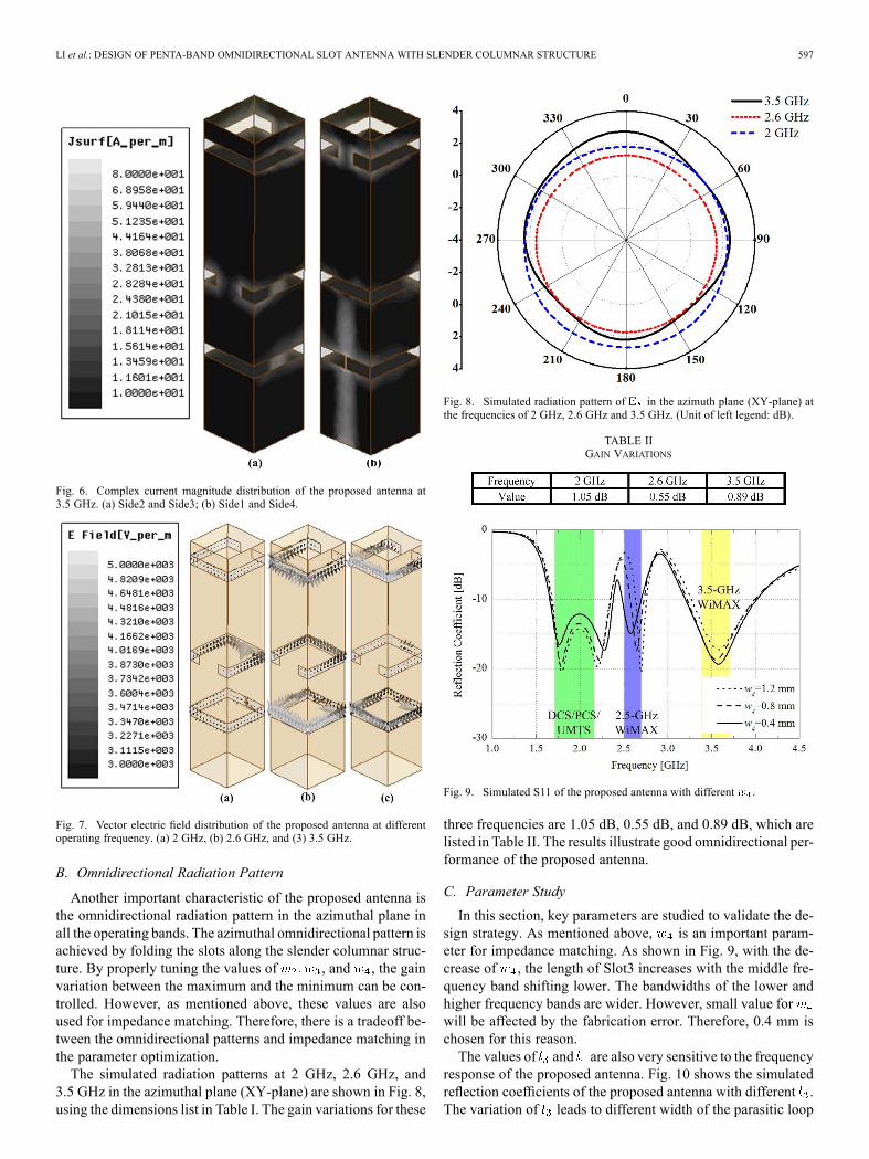
Fig. 6. Complex current magnitude distribution of the proposed antenna at3.5 GHz. (a) Side2 and Side3; (b) Side1 and Side4.
Fig. 7. Vector electric field distribution of the proposed antenna at differentoperating frequency. (a) 2 GHz, (b) 2.6 GHz, and (3) 3.5 GHz.
B. Omnidirectional Radiation Pattern
Another important characteristic of the proposed antenna isthe omnidirectional radiation pattern in the azimuthal plane inall the operating bands. The azimuthal omnidirectional pattern isachieved by folding the slots along the slender columnar struc-ture. By properly tuning the values of , and , the gainvariation between the maximum and the minimum can be con-trolled. However, as mentioned above, these values are alsoused for impedance matching. Therefore, there is a tradeoff be-tween the omnidirectional patterns and impedance matching inthe parameter optimization.The simulated radiation patterns at 2 GHz, 2.6 GHz, and
3.5 GHz in the azimuthal plane (XY-plane) are shown in Fig. 8,using the dimensions list in Table I. The gain variations for these
Fig. 8. Simulated radiation pattern of in the azimuth plane (XY-plane) atthe frequencies of 2 GHz, 2.6 GHz and 3.5 GHz. (Unit of left legend: dB).
TABLE IIGAIN VARIATIONS
Fig. 9. Simulated S11 of the proposed antenna with different .
three frequencies are 1.05 dB, 0.55 dB, and 0.89 dB, which arelisted in Table II. The results illustrate good omnidirectional per-formance of the proposed antenna.
C. Parameter Study
In this section, key parameters are studied to validate the de-sign strategy. As mentioned above, is an important param-eter for impedance matching. As shown in Fig. 9, with the de-crease of , the length of Slot3 increases with the middle fre-quency band shifting lower. The bandwidths of the lower andhigher frequency bands are wider. However, small value forwill be affected by the fabrication error. Therefore, 0.4 mm ischosen for this reason.The values of and are also very sensitive to the frequency
response of the proposed antenna. Fig. 10 shows the simulatedreflection coefficients of the proposed antenna with different .The variation of leads to different width of the parasitic loop

598 IEEE TRANSACTIONS ON ANTENNAS AND PROPAGATION, VOL. 62, NO. 2, FEBRUARY 2014
Fig. 10. Simulated S11 of the proposed antenna with different .
Fig. 11. Simulated S11 of the proposed antenna with different .
ring, which affects the resonant frequency of the higher band.With the decrease of , the resonant frequency of the middleand higher bands shift closer. The bandwidth of lower band iswider. In order to tuning the ratio between the different fre-quency bands, mm is selected.Fig. 11 shows the simulated reflection coefficients of the pro-
posed antenna with different . Due to the DGS effect, issensitive to the impedance matching for all the frequency bands.With the increase of , the dual peaks in lower band shift fur-ther from each other. The bandwidth of higher band is enhanced.The value of is also related to the impedance matching ofmiddle band. For the comprehensive consideration, mmis selected.Fig. 12 shows the simulated reflection coefficients of the pro-
posed antenna with different . The length of the microstrip lineis another important parameter for impedance matching, espe-cially for the lower band. By tuning , dual-resonant with wideimpedance bandwidth is achieved. We select mm, andthe lower band covers the DCS, PCS, and UNTS bands.The shorting positions of the triple slots are discussed here.
The Slot1 is directly fed through the microstrip line on Side4.The shorting position of Slot1 is selected on Side2. Slot3 isadopted for DGS impedance matching, and its shorting positionis selected on the same side of the microstrip line. Slot2 is fed
Fig. 12. Simulated S11 of the proposed antenna with different .
Fig. 13. Antenna application with the additional ground (equipment) with dif-ferent ground dimension.
by coupling current on the column, indirectly by the microstripline. Therefore, the shorting position of Slot2 can be selected onSide2 or Side4 with identical radiating pattern and impedancebandwidth.
D. Ground Effect Analysis
As discussed in the introduction, the proposed antenna isemployed without using large ground. In order to validate thisassumption and further emphasize this advantage, the proposedantenna was simulated with different ground plane dimensions.As shown in Fig. 13, the proposed antenna is mounted ondifferent metal boxes (e.g., main body of nearby equipment)with a distance of 5 mm. Three different dimensions of themetal boxes are used here: ground 1 (10 10 10 mm ) inFig. 13(a), ground 2 (40 20 10 mm ) in Fig. 13(b) andground 3 (100 50 10 mm ) in Fig. 13(c).Fig. 14 shows the simulated reflection coefficients of the pro-
posed antenna when placed near metal boxes of different di-mensions. As it may be seen, the performance of the proposedantenna continued to be acceptable (i.e., maintained excellentpenta-band coverage) even with the presence of nearby metalequipment. The monopole antenna in [8]–[10], on the otherhand, cannot operate without a large ground, especially for thesituation of ground 1 in Fig. 13(a). The proposed antenna can

LI et al.: DESIGN OF PENTA-BAND OMNIDIRECTIONAL SLOT ANTENNA WITH SLENDER COLUMNAR STRUCTURE 599
Fig. 14. Simulated S11 of the proposed antenna with different additionalground (equipment).
Fig. 15. Photograph of the proposed antenna.
be designed separately without considering the dimensions ofassociated transmitting or receiving equipment.
III. EXPERIMENTAL RESULTS
In order to prove the design strategy, a prototype of the pro-posed antenna was built and measured, as shown in Fig. 15.The antenna prototype consists of four printed circuit boards(PCBs), and the seams between four PCBs are covered usingfoil. Folding the soft PCB is also an acceptable way to buildthe antenna. The antenna prototype was fed by 50- coaxial ca-bles. As we know, the feeding coaxial cables can be treated as anextension of the metal ground. To avoid the radiating of the cur-rent along the feeding coaxial cables, a series of magnetic beadsare used to choke the surface current on the feeding cables. Thedetailed connection figure is also shown in Fig. 15. The innerconductor of the coaxial cable is soldered with the feeding mi-crostrip line. The outer conductor is soldered with the metal onSide4.The measured results of reflection coefficient are illustrated
in Fig. 16, and compared with the simulated results. ThedB bandwidths of the reflection coefficient are 1.69–2.37 GHzfor the lower band, 2.47–2.72 GHz for the middle band and
Fig. 16. Measured and simulated S11 of the proposed antenna.
Fig. 17. Simulated andmeasured normalized radiation patterns of the proposedantenna at 2 GHz. (a) XY-plane; (b) YZ-plane; (c) XZ-plane.
3.23–4.09 GHz for the higher band. Once again, wide band-width is achieved in a small volume of 50 10 10 mm( is the wavelength in freespace at 1.71 GHz), without using extra ground.The measured normalized radiation patterns at 2 GHz,
2.6 GHz, and 3.5 GHz are shown in Figs. 17, 18, and 19,also compared with the simulated results. It is clearly seenthat the omnidirectional radiation patterns are achieved forco-polarization in the azimuthal plane (XY-plane) at all thethree frequencies, and agree well with the simulated ones.In XZ-plane and YZ-plane, the radiation patterns are nearly“ ”shaped with the nulls at axis. Due to the undesiredradiation and reflection from the feeding cables, the cross-polarization level is higher than the simulated results. Thedifference between simulation and measurement is acceptable,given the small values of the cross-polarization powers.Fig. 20 shows the measured gain of the proposed antenna in
the azimuthal plane, and compared with the simulation results.In the band of DCS, PCS, and UMTS, the measured gain fluc-tuates between 1.95 dBi and 2.55 dBi. In the band of 2.5-GHz

600 IEEE TRANSACTIONS ON ANTENNAS AND PROPAGATION, VOL. 62, NO. 2, FEBRUARY 2014
Fig. 18. Simulated andmeasured normalized radiation patterns of the proposedantenna at 2.6 GHz. (a) XY-plane; (b) YZ-plane; (c) XZ-plane.
Fig. 19. Simulated andmeasured normalized radiation patterns of the proposedantenna at 3.5 GHz. (a) XY-plane; (b) YZ-plane; (c) XZ-plane.
WiMAX, the measured gain fluctuates between 0.7 dBi and1.12 dBi. In the band of 3.5-GHz WiMAX, the measured gainfluctuates between 2.6 dBi and 2.64 dBi. The results are accept-able for practical applications.
IV. CONCLUSION
This paper proposed a penta-band omnidirectional antennausing three co-located slots on a square columnar structure. Theslots not only play the roles of radiating elements, but also serveas the defected ground for impedance matching. The proposedantenna is able to cover five bands, including the bands of DCS,PCS, UMTS, 2.5-GHz WiMAX, and 3.5-GHz WiMAX. Theomnidirectional radiation patterns are achieved in the azimuthal
Fig. 20. Simulated and measured gains of the proposed antenna.
plane for all the operating bands, due to the compact squarecolumnar structure. The overall volume of the proposed antennais only 50 10 10 mm , which is suited for the volume-lim-ited systems. The measured gains of each operating bands arealso acceptable for the application in the portable base stationsand access points.
ACKNOWLEDGMENT
The authors would like to thank C. Deng and G. Pan from theDepartment of Electronic Engineering, Tsinghua University, fortheir help, particularly with antenna fabrication and measure-ments. They would like to thank the reviewers for their com-ments and suggestions, which are valuable in improving thepaper and also important for our future research.
REFERENCES[1] Q. Chu and L. Ye, “Design of compact dual-wideband antenna with
assembled monopoles,” IEEE Trans. Antennas Propag., vol. 58, no.12, pp. 4063–4066, Dec. 2010.
[2] W. Liu, C. Wu, and Y. Dai, “Design of triple-frequency microstrip-fedmonopole antenna using defected ground structure,” IEEE Trans. An-tennas Propag., vol. 59, no. 7, pp. 2457–2463, Jul. 2011.
[3] C. Pan, T. Horng, W. Chen, and C. Huang, “Dual wideband printedmonopole antenna for WLAN/WiMAX applications,” IEEE AntennasWireless Propag. Lett., vol. 6, pp. 149–151, 2007.
[4] W. Liu, C.Wu, and Y. Tseng, “Parasitically loaded CPW-fedmonopoleantenna for broadband operation,” IEEE Trans. Antennas Propag., vol.59, no. 6, pp. 2415–2419, Jun. 2011.
[5] S. Palud, F. Colombel, M. Himdi, and C. Meins, “Wideband omnidi-rectional and compact antenna for VHF/UHF band,” IEEE AntennasWireless Propag. Lett., vol. 10, pp. 3–6, 2011.
[6] R. Zaker and A. Abdipour, “A very compact ultrawideband printedomnidirectional monopole antenna,” IEEE Antennas Wireless Propag.Lett., vol. 9, pp. 471–473, 2010.
[7] C. Tseng and C. Huang, “A wideband cross monopole antenna,” IEEETrans. Antennas Propag., vol. 57, no. 8, pp. 2464–2468, Jun. 2009.
[8] K. Wong and C. Wu, “Wide-band omnidirectional square cylindricalmetal-plate monopole antenna,” IEEE Trans. Antennas Propag., vol.53, no. 8, pp. 2758–2761, Jun. 2005.
[9] K. Wong, S. Su, and C. Tang, “Broadband omnidirectional metal-platemonopole antenna,” IEEE Trans. Antennas Propag., vol. 53, no. 1, pp.581–583, Jan. 2005.
[10] X. Wu and A. Kishk, “Study of an ultrawideband omnidirectionalrolled monopole antenna with trapezoidal cuts,” IEEE Trans. AntennasPropag., vol. 56, no. 1, pp. 259–263, Jan. 2008.
[11] R. Bancroft and B. Bateman, “An omnidirectional planarmicrostrip an-tenna,” IEEE Trans. Antennas Propag., vol. 52, no. 7, pp. 3151–3153,Jul. 2004.

LI et al.: DESIGN OF PENTA-BAND OMNIDIRECTIONAL SLOT ANTENNA WITH SLENDER COLUMNAR STRUCTURE 601
[12] F. Hsiao and K. Wong, “Omnidirectional planar folded dipole an-tenna,” IEEE Trans. Antennas Propag., vol. 52, no. 2, pp. 1898–1902,Feb. 2004.
[13] K. Wei, Z. Zhang, W. Chen, Z. Feng, and M. Iskander, “A tribandshunt-fed omnidirectional planar dipole array,” IEEE Antennas Wire-less Propag. Lett., vol. 9, pp. 850–853, 2010.
[14] J. Li, “An omnidirectional microstrip antenna for WiMAX applica-tions,” IEEE Antennas Wireless Propag. Lett., vol. 10, pp. 167–169,2011.
[15] H. Chreim, E. Pointereau, B. Jecko, and P. Dufrane, “Omnidirectionalelectromagnetic band gap antenna for base station applications,” IEEEAntennas Wireless Propag. Lett., vol. 6, pp. 499–502, 2007.
[16] E. Pointereau, H. Chreim, B. Jecko, and P. Dufrane, “Omnidirectionalcylindrical electromagnetic bandgap antenna with dual polarization,”IEEE Antennas Wireless Propag. Lett., vol. 6, pp. 450–453, 2007.
[17] A. Borja, P. Hall, Q. Liu, and H. Iizuka, “Omnidirectional loop antennawith left-handed loading,” IEEE Antennas Wireless Propag. Lett., vol.6, pp. 495–498, 2007.
[18] J. Zhu, M. Antoniades, and G. Eleftheriades, “A compact tri-bandmonopole antenna with single-cell metamaterial loading,” IEEETrans. Antennas Propag., vol. 58, no. 4, pp. 1031–1038, Feb. 2010.
[19] R. Isom, M. Iskander, Z. Yun, and Z. Zhang, “Design and developmentof multiband coaxial continuous transverse stub (CTS) antenna arrays,”IEEE Trans. Antennas Propag., vol. 52, no. 8, pp. 2180–2184, Aug.2004.
[20] C. Ahn, S. Oh, and K. Chang, “A dual-frequency omnidirectional an-tenna for polarization diversity of MIMO and wireless communica-tion applications,” IEEE Antennas Wireless Propag. Lett., vol. 8, pp.996–999, 2009.
[21] G. Shiroma and W. Shiroma, “A two-element L-band Quasi-Yagiantenna array with omnidirectional coverage,” IEEE Trans. AntennasPropag., vol. 55, no. 12, pp. 3713–3716, Dec. 2007.
[22] M. Wong, A. Sebak, and T. Denidni, “Analysis of a dual-band dual slotomnidirectional stripline antenna,” IEEE Antennas Wireless Propag.Lett., vol. 6, pp. 199–202, 2007.
Yue Li (S’11–M’12) received the B.S. degrees intelecommunication engineering from the ZhejiangUniversity, Zhejiang, China, in 2007, and the Ph.D.degree from Tsinghua University, Beijing, China, in2012.Since 2012, he has been with Tsinghua University,
where he is a Postdoctoral Fellow in the Departmentof Electronic Engineering. His current research in-terests include reconfigurable antennas, electricallysmall antennas, mobile antennas, diversity antennas,and antennas in package. He is a reviewer of the IEEE
TRANSACTIONS ON ANTENNAS AND PROPAGATION and the IEEE ANTENNASAND WIRELESS PROPAGATION LETTERS.
Zhijun Zhang (M’00–SM’04) received the B.S. andM.S. degrees from the University of Electronic Sci-ence and Technology of China, in 1992 and 1995, re-spectively, and the Ph.D. degree from Tsinghua Uni-versity, Beijing, China, in 1999.In 1999, he was a Postdoctoral Fellow with the
Department of Electrical Engineering, University ofUtah, Salt Lake City, UT, USA, where he was ap-pointed a Research Assistant Professor in 2001. InMay 2002, he was an Assistant Researcher with theUniversity of Hawaii at Manoa, Honolulu, HI, USA.
In November 2002, he joined Amphenol T&M Antennas, Vernon Hills, IL,USA, as a Senior Staff Antenna Development Engineer and was then promotedto the position of Antenna Engineer Manager. In 2004, he joined Nokia Inc.,San Diego, CA, USA, as a Senior Antenna Design Engineer. In 2006, he joinedApple Inc., Cupertino, CA, USA, as a Senior Antenna Design Engineer andwas then promoted to the position of Principal Antenna Engineer. Since August2007, he has been with Tsinghua University, China, where he is a Professorin the Department of Electronic Engineering. He is the author of Antenna De-sign for Mobile Devices (Wiley, 2011). He is an Associate Editor of the IEEETRANSACTIONS ON ANTENNAS AND PROPAGATION and the IEEE ANTENNASAND WIRELESS PROPAGATION LETTERS.
Zhenghe Feng (M’05–SM’08–F’12) received theB.S. degree in radio and electronics from TsinghuaUniversity, Beijing, China, in 1970.Since 1970, he has been with Tsinghua University,
China, as an Assistant, Lecturer, Associate Pro-fessor, and Full Professor. His main research areasinclude numerical techniques and computationalelectromagnetics, RF and microwave circuits andantennas, wireless communications, smart antennas,and spatial temporal signal processing.
Magdy F. Iskander (S’72–M’76–SM’84–F’93–LF’12) is the Director of the Hawaii Center forAdvanced Communications (HCAC), Collegeof Engineering, University of Hawaii at Manoa,Honolulu, HI, USA. He is Co-Director the NSFIndustry/University Cooperative Research Centerwith four other universities.From 1997–1999, he was a Program Director at
the National Science Foundation, where he formu-lated a “Wireless Information Technology” Initiativein the Engineering Directorate. He edited two spe-
cial issues of the IEEE TRANSACTIONS ON ANTENNAS AND PROPAGATION onWireless Communications Technology in 2002 and 2006 and co-edited a spe-cial issue of the IEICE Journal in Japan in 2004. He was the 2002 Presidentof IEEE Antennas and Propagation Society (AP-S) and a Distinguished Lec-turer for the IEEE AP-S (1994–1997). He authored the textbook Electromag-netic Fields and Waves (Prentice Hall, 1992, and Waveland Press, 2001; secondedition 2012); edited theCAEME Software Books, Vol. I, II 1991–94; and editedfour books onMicrowave Processing of Materials (Materials Research Society,1990–1996). He has published over 230 papers in technical journals, holds eightpatents, and has made numerous presentations at national and international con-ferences. He is the founding editor of theComputer Applications in EngineeringEducation (CAE) journal, published by Wiley (1992–present). Much of his re-search is funded by the National Science Foundation, the U.S. Army CERDEC,and the Office of Naval Research, as well as several corporate sponsors. As aresult of an NSF Major Research Instrumentation grant, he established wire-less testbeds, indoor antenna ranges, microwave network analysis labs, and anRF fabrication and characterization lab at the University of Hawaii at Manoa.His Center HCAC has an ongoing ten-year grant (2005–2014) for partnershipin the NSF Industry/University Cooperative Research Center in Telecommu-nications with the University of Arizona, Arizona State University, RPI, andThe Ohio State University. His research focus is on antenna design and propa-gation modeling for wireless communications and radar systems and his grouprecently received two NSF grants and CERDEC funding for the development ofthe “Microwave Stethoscope” for vital signs and changes in lung water contentmeasurement.Dr. Iskander has received many teaching excellence and research awards, in-
cluding the 2012 University of Hawaii Board of Regent Medal for Excellencein Research and the 2010 Board of Regents’ Medal for Teaching Excellence. In2012, he received the IEEE AP-S Chen-To Tai Distinguished Educator Awardand the 2013 IEEEMTT-S Distinguished Educator Award. He also received the2010 Northrop Grumman Excellence in Teaching Award, the 2011 Hi ChangChai Outstanding Teaching Award, and the University of Utah DistinguishedTeaching Award in 2000. In 1985, he received the ASEE Curtis W. McGrawNational Research Award, and in 1991, he received the ASEE George Westing-house National Education Award. 1992, he also received the Richard R. Stod-dard Award from the IEEE EMC Society. He was a member of the 1999 WTECpanel on “Wireless Information Technology-Europe and Japan”, and chairedtwo International Technology Institute Panels on “Asian TelecommunicationTechnology” sponsored by NSF/DoD in 2001 and 2003.