design of passively safe portal signal gantries · however, although the scope of bs en 12767...
TRANSCRIPT
Interim Advice Note 85/07(W) Design of passively safe portal signal gantries
IAN 85/07(W) Page 1 of 58 Jun 07
INTERIM ADVICE NOTE 85/07(W) DESIGN OF PASSIVELY SAFE PORTAL SIGNAL GANTRIES SUMMARY This IAN sets out the performance requirements for the design of passively safe portal signal gantries.

Interim Advice Note 85/07(W) Design of passively safe portal signal gantries
IAN 85/07(W) Page 2 of 58 Jun 07
Contents Chapter 1. Introduction 2. Terminology and Definitions 3. General Requirements and Principles 4. Suitability 5. Risk Assessment and Cost Benefit Analysis 6. Performance Requirements 7. Loadings 8. Dynamic Analysis 9. Design 10. Design Considerations 11. Foundations 12. Appearance 13. References 14. Enquiries Appendices: A Typical Equipment and Cabling B Passively safe gantry risk model user guide
Interim Advice Note 85/07(W) Design of passively safe portal signal gantries
IAN 85/07(W) Page 3 of 58 Jun 07
1 INTRODUCTION General Background 1.1 There is a need for the Welsh Assembly Government to increase the amount of driver information and traffic control equipment that is installed on the trunk road network. To do this, more gantries are required. Traditional gantries are generally of solid construction, high cost and require the use of a higher containment vehicle restraint to (a) minimise any risk to an errant vehicle if it hits the gantry; and (b) to ensure that the gantry will not collapse on impact. 1.2 In general, passively safe gantries are lighter weight in construction and do not necessarily require a high containment barrier as the structure is designed so that impact with the legs will not cause major injury. They can be cheaper in whole-life cost terms, and are viable in certain conditions. 1.3 The requirements for passive safety in this document make use of BS EN 12767, “Passive safety of support structures for road equipment – Requirements and test methods”. However, although the scope of BS EN 12767 includes portal gantries, it is largely written for single supports such as lighting columns. It was therefore found necessary to depart from some of the provisions in the EN in developing the design requirements. 1.4 If having reviewed this Interim Advice Note (IAN), a passively safe gantry solution is not viable for a particular application, reference should be made to BD 51 (DMRB 2.2.4) and any future amendments and revisions for gantries not meeting the passively safe design criteria. 1.5 It is proposed that all gantry options, including passively safe designs, will be incorporated into a single fully revised BD 51 (possibly re-named) in due course, but in the meantime for expediency this Interim Advice Note (IAN 85/07) is being issued to cover passively safe designs. Formal Application to use IAN 85/07 1.6 This document outlines the performance requirements for passively safe gantries. To date it has been reviewed by an internal Technical Project Board (TPB) consisting of technical experts and industry representatives. To allow Industry to have early visibility of this document, the Welsh Assembly Government has decided to issue it for use at the same time as seeking wider feedback. All feedback will be collated and used to improve and finalise the performance requirements. 1.7 This IAN is therefore to be treated as an interim Standard. As it is not a full Standard, the Welsh Assembly Government wishes to monitor its application to (a) assess the number of schemes using passively safe gantries; and (b) ensure that any modifications or updates to this document can be issued to the users as quickly as possible. 1.8 Formal application to use this IAN is required from Design Organisations / Agents on a scheme specific basis. Applications should be submitted directly to the appropriate Project Director or Area Manager as applicable. If supported, the submission of a Departure from Standard for ‘aspects not covered by Standards’ is then required. Mandatory Requirements 1.9 Sections of this document that are mandatory requirements of the Welsh Assembly Government are contained within boxes. The remainder of the document contains advice and enlargement, which is recommended for consideration.

Interim Advice Note 85/07(W) Design of passively safe portal signal gantries
IAN 85/07(W) Page 4 of 58 Jun 07
Scope 1.10 This document specifies criteria and advice for the design of passively safe portal signal gantries (for use on motorways and all-purpose roads), where any part of the sign or motorway signal and their supporting structure is mounted over the carriageway, central reserve, hard shoulder, and/or hard strip. The gantries may also support small signs. Limitations 1.11 Structures to support signs and signals are provided to perform some or all of the following functions:
i) Support signals and associated equipment.
ii) Where required support other equipment, such as microwave aerials, tolling equipment and traffic detection equipment.
iii) Support small directional signs in place of the signals noted above. The signs will generally be no greater than the overall dimensions of the signals.
iv) Support the cable management system, distribution boxes, isolators and cable marshalling units required for the power and communication cabling associated with the equipment in i), ii) and iii) above.

Interim Advice Note 85/07(W) Design of passively safe portal signal gantries
IAN 85/07(W) Page 5 of 58 Jun 07
2 TERMINOLOGY AND DEFINITIONS Terminology2.1 The meaning and definition of terms are generally be in accordance with BS 6100, unless otherwise defined below: Carriageway 2.2 For the purpose of this document, the carriageway width is taken to be the running surface, which includes all traffic lanes, hard shoulders, hard strips and marker strips, between raised kerbs. In the absence of raised kerbs it is the width between safety fences, less the amount of set back required for these fences, being not less than 0.6m or more than 1.0m from the traffic face of each fence. The carriageway width shall be measured in a direction at right angles to the line of the raised kerbs, lane markings or edge markings. Gantry 2.3 Generic term for a structure supporting signs or signals including Variable Message Signs (VMS) cantilever structures, single and multiple portals. This IAN only covers portal structures. Sign 2.4 A device carrying directional or other informational message, e.g. route information at the approach to a junction. Signal 2.5 A device which uses lights to give advisory or mandatory instructions, e.g. red “X” lane closures or speed restriction. Variable Message Sign (VMS) 2.6 A generic term describing a signal displaying text messages and / or symbols. Road Restraint System (RRS) 2.7 Installation to provide a level of containment for errant vehicles to limit damage or injury to users of the highway. Passive Safety 2.8 Passively safe structures are those that are designed to yield or detach under vehicle impact in order to limit injury to the vehicle occupants. This IAN considers the passive safety of gantries. It assumes there are no other obstructions in the area which inhibit passively safe behaviour. In order to ensure passively safe behaviour it is necessary to consider the area as a whole. This is likely to involve, for example, either moving cabinets out of the possible path of errant vehicles or using passively safe cabinets. Scheme Design 2.9 The Scheme Design is the overall design of the length of carriageway, including but not limited to carriageway alignment, control strategy, equipment selection, signing, and gantry positioning. This design will typically be carried out by the Employer’s Agent or the Contractor’s Designer, who shall be known as the Scheme Designer. Gantry Design 2.10 The design of the gantry structure and attachments, including superstructure, foundations, equipment supports, and interfaces. This design will typically be carried out by a Designer or Designers who may or may not be the Scheme Designer. These Designers shall be known as the Gantry Designer.

Interim Advice Note 85/07(W) Design of passively safe portal signal gantries
IAN 85/07(W) Page 6 of 58 Jun 07
Gantry Leg 2.11 This is the support structure at each end of the gantry, and in the central reserve in the case of two span gantries, providing the vertical clearance to the carriageway and an access route for power and communications cabling. It may comprise of more than one element. Gantry Boom 2.12 This is the horizontal portion of the gantry spanning the carriageway between legs. It includes the mounting points for the various signals and signs and provides a route for power and communications cabling.

Interim Advice Note 85/07(W) Design of passively safe portal signal gantries
IAN 85/07(W) Page 7 of 58 Jun 07
3 GENERAL REQUIREMENTS AND PRINCIPLES Design Process3.1 Gantries designed using this IAN are intended to supplement those designed using BD 51 (DMRB 2.2.4). Their primary function will be to support traffic control and monitoring equipment and driver information systems. Their secondary function will be to support small fixed text Advanced Direction Signs (ADS). It is not envisaged that these ADS signs will be mounted on gantries which also carry signals. 3.2 The Scheme Designer shall carry out a risk assessment and whole-life costing analysis in accordance with Section 5 to reach a "go - no go” decision for the use of passively safe gantry structures. If this analysis shows that there is sufficiently low risk and a saving in whole-life cost, passively safe gantries may be used and designed in accordance with the requirements of this IAN. Technical Approval 3.3 The designs for construction, alteration and re-positioning of sign/signal portal and cantilever gantries shall comply with the requirements of BD 2 Part 1 (DMRB 1.1.1). The Design organisation shall give consideration to the appropriate procedure for the procurement of sign gantries in accordance with the requirements of Annex D of BD 2. General Aspects of Design Access 3.4 Gantries designed using this IAN must not be provided with a fixed means of access for inspection and maintenance. The designer shall consider how inspection and maintenance access is to be provided and a methodology developed and submitted as part of the approval process. The design shall include any fixing points, hard points, etc. required on the gantry structure to facilitate this access. The Gantry Designer shall also liaise with the Scheme Designer to ensure that the carriageway alignment and construction is sufficient to support the proposed maintenance and inspection methodology. Adaptability 3.5 Structural holding down bolt arrangements and foundations shall be designed such that subsequent removal and replacement of the gantry structure may be readily undertaken. 3.6 The Gantry Designer must consider whether to allow in the design for the likely future repositioning of, or changes to loading from, equipment or signage on the gantry, taking into account the probability of this within the operational life of the gantry. The decision to make such provision must be agreed with the Overseeing Organisation and recorded in the Approval in Principle. Where provision is made for future changes, adequate detail must be provided on drawings to indicate the extent of such provision Operational and design life 3.7 The operational life for new gantries (i.e. the time during which the gantry is assumed to remain safely in use at that site) is to be 30 years. In the design for wind and temperature environmental effects, the return period must be taken as the operational life of the gantry. In the design for fatigue, the design life must be based on a period of operational life plus 10 years i.e. 40 years.

Interim Advice Note 85/07(W) Design of passively safe portal signal gantries
IAN 85/07(W) Page 8 of 58 Jun 07
3.8 If there is a requirement for the gantry to remain operational beyond its design life it will be necessary for the maintaining authority to carry out a special inspection to verify the continuing ability of the structure to perform its function. This may include material testing such as ultrasonic investigation of welds. It may also require refurbishment of the structure including replacement of bolts, protection systems etc. Environmental 3.9 Due consideration shall be given to minimising the environmental impacts of the gantry design including visual and material aspects. Erection / demounting 3.10 The design shall minimise the disruption to road users by ensuring that erection can take place in short periods of time. 3.11 Where the gantry is not designed to be erected in one piece, the legs shall be self stable to allow a staged construction process. Vandalism 3.12 Measures shall be taken to reduce the risk of theft of materials, such as aluminium alloy and copper, and to minimise the risk of vandalism to equipment. Climb Resistance 3.13 Wherever practicable the arrangement or detailing of the legs should be such as to prevent them being used as a means of ready access to the boom, particularly at gantries located close to areas of habitation. Any measures used to prevent such access to the boom should be included in the passive safety testing arrangement. (See Chapter 6 for testing requirements) Procurement Route 3.14 The procurement of gantries will normally be carried out under contracts incorporating the Specification for Highway Works (MCHW). In such cases products conforming to equivalent standards and specifications of other member states of the European Economic Area and tests undertaken in other member states will be acceptable in accordance with the terms of the 104 and 105 Series of Clauses of that Specification. Any Contract not containing these Clauses must contain suitable clauses of mutual recognition having the same effect, regarding which advice should be sought. Robustness 3.15 The gantry arrangement and components shall be sufficiently robust to resist damage during transportation and erection. Mounting systems for equipment shall enable the gantry to be transported and erected with the equipment in place. Layout 3.16 All elements shall comply with TD 27 (DMRB 6.1.2) after allowing for deflections due to dead, live, wind, snow loads and temperature in the serviceability limit state combinations 1 to 5. The ends of the boom shall be at the same level and the structure will comply with the requirements of 9.8.

Interim Advice Note 85/07(W) Design of passively safe portal signal gantries
IAN 85/07(W) Page 9 of 58 Jun 07
Equipment 3.17 All signs, signals and associated equipment shall be securely attached to the structure using robust and durable fixings consistent with the gantry design. The structural design shall make adequate provision for the attachment of equipment. Any subsequent modifications to structural members and attachment of additional pieces of equipment shall only be carried out with the approval of the TAA in accordance with BD 2 (DMRB 1.1.1). Structural Connections 3.18 Access walkways are not provided for gantries designed to this IAN. Therefore to aid inspection procedures, wherever possible, the connections between main structural elements should be visible from ground level at the hard shoulder or verge. Identification 3.19 The structure site identification marking of gantries shall be in accordance with Departmental Standard BD 45 (DMRB 3.1.1). In addition the gantry shall be marked as being a Passively Safe design and attention drawn to clauses 3.3 and 3.17 of this IAN. Use of Dissimilar Metals 3.20 Where dissimilar metals are to be used, the connections shall be designed to avoid the risk of galvanic corrosion. The electrical bonding of all metal components must nonetheless be maintained. Road Restraint Systems 3.21 Gantries designed to this IAN shall comply with the passive safety requirements of Chapter 6 even if they are protected by Road Restraint Systems. Temporary Condition 3.22 Consideration should be given to using the structures to assist in the construction works traffic management scheme. Such a use of a permanent gantry should not compromise its performance in its permanent role.

Interim Advice Note 85/07(W) Design of passively safe portal signal gantries
IAN 85/07(W) Page 10 of 58 Jun 07
4 SUITABILITY Siting 4.1 The gantries shall be used at locations where large advanced direction signs are not required. This will typically be on lengths of motorway between junctions. 4.2 A gantry leg shall not be located within 2.5m of other equipment that could present a hazard to vehicles unless the interaction of the two pieces of equipment is considered in the passive safety assessment. Equipment 4.3 The equipment that a gantry is required to carry shall be defined in the Approval in Principle (AIP). An illustrative list of typical equipment and cabling requirements is provided in Appendix A. The information contained in Appendix A is for guidance only and should not be treated as definitive 4.4 Gantries shall not be used to carry equipment or cabling that is more onerous in relation to passive safety than that considered in the tests described in Chapter 6. 4.5 If special plugs or other systems are used to avoid the cabling over-constraining the structure during the passive safety tests, systems with equivalent or better performance shall be used in the real structure. 4.6 The gantry cabling shall be designed so that whichever part of the gantry is impacted, the electrical current of whatever voltage to / from the structure shall be automatically isolated from a point immediately above ground level.

Interim Advice Note 85/07(W) Design of passively safe portal signal gantries
IAN 85/07(W) Page 11 of 58 Jun 07
5 RISK ASSESSMENT AND COST BENEFIT ANALYSIS Purpose of Risk Assessment and Cost Benefit Analysis 5.1 A risk assessment and cost benefit analysis is required to inform the decision whether or not a passively safe gantry is appropriate for use at a particular site. Scope 5.2 The risk assessment shall take account of: Relative safety and journey time reliability risks of different proposed gantry types
or designs Road user, operative and 3rd party risks ‘Adaptability’ risks associated with any constraints on future functionality arising
from the proposed gantry design The cost benefit analysis shall then compare these risks with the relative costs of the different proposed gantry types or designs. Risks and costs shall be considered on a whole-life basis. Process 5.3 The minimum requirement shall be to compare the relative whole life risks and costs associated with the use of a passively safe gantry at a site, with the whole life risks and costs associated with the use of a ‘standard’ BD 51 gantry at a site. Figure 5.1 shows the gantry assessment process. Figure 5.1 Gantry Assessment Process
Interim Advice Note 85/07(W) Design of passively safe portal signal gantries
IAN 85/07(W) Page 12 of 58 Jun 07
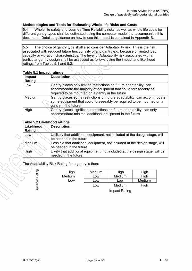
Methodologies and Tools for Estimating Whole-life Risks and Costs 5.4 Whole life safety and Journey Time Reliability risks, as well as whole life costs for different gantry types shall be estimated using the computer model that accompanies this document. Detailed guidance on how to use this model is contained in Appendix B. 5.5 The choice of gantry type shall also consider Adaptability risk. This is the risk associated with reduced future functionality of any gantry e.g. because of limited load capacity or vibration characteristics. The level of Adaptability risk associated with a particular gantry design shall be assessed as follows using the impact and likelihood ratings from Tables 5.1 and 5.2: Table 5.1 Impact ratings Impact Rating
Description
Low Gantry places only limited restrictions on future adaptability; can accommodate the majority of equipment that could foreseeably be required to be mounted on a gantry in the future
Medium Gantry places some restrictions on future adaptability; can accommodate some equipment that could foreseeably be required to be mounted on a gantry in the future
High Gantry places significant restrictions on future adaptability; can only accommodate minimal additional equipment in the future
Table 5.2 Likelihood ratings Likelihood Rating
Description
Low Unlikely that additional equipment, not included at the design stage, will be needed in the future
Medium Possible that additional equipment, not included at the design stage, will be needed in the future
High Likely that additional equipment, not included at the design stage, will be needed in the future
The Adaptability Risk Rating for a gantry is then:
High Medium High High
Medium Low Medium High Low Low Low Medium
Low Medium High
Like
lihoo
d R
atin
g
Impact Rating

Interim Advice Note 85/07(W) Design of passively safe portal signal gantries
IAN 85/07(W) Page 13 of 58 Jun 07
“Go – no go” Decision Criteria 5.6 The final decision whether to use a passively safe gantry for a particular site shall be informed by consideration of the relative whole-life risks and costs of this type of gantry compared with a ‘standard’ BD 51 design. 5.7 When assessing the acceptability of relative safety risks of a passively safe gantry compared with a ‘standard’ gantry, designers need to consider changes in safety risk to individual user groups as well as changes in total risk. For example, it is possible to have a reduced total risk for a passively safe gantry but within this to have an increased risk to operatives. The acceptability of this type of increase in safety risk shall be agreed with the Welsh Assembly Government. 5.8 The acceptability of any trade-offs between increased or decreased safety risk versus journey time reliability impact and whole-life cost associated with the use of a passively safe gantry shall be agreed with the Welsh Assembly Government. Record Keeping 5.9 Designers shall formally record all the factors considered in the risk assessment. This will include: the features and hazards present or known about at the time sources of data used to inform the risk assessment justification for the decisions made in the risk assessment

Interim Advice Note 85/07(W) Design of passively safe portal signal gantries
IAN 85/07(W) Page 14 of 58 Jun 07
6 PERFORMANCE REQUIREMENTS PASSIVE SAFETY Introduction 6.1 The severity of accidents for occupants of a vehicle striking a gantry is typically affected by the performance of the gantry legs under impact. These can be made in such a way that they detach or yield under vehicle impact. BS EN 12767 covers the general design of these types of structure and this standard refers to it and gives more specific requirements for gantries. BS EN 1317 is also referred to. 6.2 Gantry structures with no performance requirements for passive safety are class 0 in accordance with BS EN 12767 and these structures should be designed in accordance with BD 51 (DMRB 2.2.4), see 1.1 to 1.4. 6.3 BS EN 12767 considers three categories of passively safe support structures:
high energy absorbing (HE); low energy absorbing (LE); non-energy absorbing (NE).
Energy absorbing gantry structures slow the vehicle considerably and thus the risk of secondary accidents with structures, trees, pedestrians or other road users can be reduced. Non-energy absorbing gantry structures permit the vehicle to continue after the impact with a limited reduction in speed. Non-energy absorbing gantry structures may provide a lower primary injury risk than energy absorbing gantry structures. It is envisaged that the gantry structures could be either energy absorbing or non-energy absorbing depending on their design. 6.4 BS EN 12767 requires the boom of gantries to remain 4m (or other height depending on National Regulations) above the carriageway. Because the UK has significant numbers of vehicles, including coaches, above this height, it has been increased to 5.03m in this IAN. However, since it was decided it might not be practical to comply with this for all cases, particularly for single span gantries, it was decided to allow the alternative of undertaking passive safety tests on the boom. Therefore, the following gives general requirements for passive safety testing followed by details of the leg test, criteria for avoiding the requirement for the boom test and finally requirements for the boom test when required. General Requirements for Passive Safety Testing 6.5 The passive safety testing shall be in accordance with BS EN 12767 and Chapter 6 of this document. In particular the Test, Site, Test Vehicle, Calibration Test and Test Recording shall be in accordance with BS EN 12767. 6.6 The design of the testing regime, test absorption class and the testing itself shall be verified by an independent organisation. Details of the proposed approach shall be submitted with the AIP. Severity Level 6.7 The maximum severity levels for vehicle occupants involved in an impact evolution are stated in BS EN 12767 and consider two criteria; Acceleration Severity Index, and Theoretical Head Impact Velocity, descriptions of which are as follows:

Interim Advice Note 85/07(W) Design of passively safe portal signal gantries
IAN 85/07(W) Page 15 of 58 Jun 07
Acceleration severity index (ASI) This value is calculated from the triaxial vehicle accelerations. The maximum ASI value is considered to be an assessment of the accident severity for the occupants of the impacting vehicle. ASI is a non-dimensional quantity and is calculated in accordance with BS EN 1317-1. Theoretical head impact velocity (THIV) Velocity, expressed in km/h, at which a hypothetical "point mass" occupant impacts the surfaces of a hypothetical occupant compartment. THIV is calculated in accordance with BS EN 1317-1. Vehicle Impact Speed 6.8 The gantry shall be designed for one of the vehicle speed classes listed in Table 6.1. The speed class used shall be defined in the AIP but shall normally be 100km/h unless the road is subject to a permanent speed limit of 80km/h or less. Analysis shall also be undertaken for the low speed (35km/h) test from BS EN 12767. If this indicates that this is a worse case, testing for the low speed test in BS EN 12767 shall also be carried out. Table 6.1 Vehicle Impact Speed
Speed class Impact speed for testing (km/h)
50 50 70 70 100 100
Foundations 6.9 The structure shall be designed to yield or fail leaving the foundation unaffected and reusable. (See 11.1 and 11.2). Where it can be demonstrated that the foundation is significantly stiffer than the gantry it will not normally be necessary to replicate the foundation to be used at a specific installation in the test. However, the connection to the foundation used in the testing shall be the same as that to be used at the final installed location. Where the type of foundation is not significantly stiffer than the gantry structure it will be necessary to include the foundation in the testing. Justification for the testing approach shall be submitted with the AIP. (See 6.6). Equipment on Gantry in Test 6.10 The gantry shall be tested with all equipment in position. This shall include any cabling that crosses sections of the gantry predicted to yield or detach including typical underground cables and connection boxes and/or fuse units where applicable. If it is proposed to avoid testing the gantry with all the electronics in place, the corresponding cabinets shall be ballasted to match the weight and centre of gravity of the individual items of equipment. On structures that require boom tests, additional measures may be required to ensure that this does not result in major differences in the inertia or stiffness of cabinets compared with those with the real equipment installed. Test Gantry 6.11 Where otherwise similar gantries are to be used with different spans, it will be acceptable to test only one span provided calculations or other evidence is submitted to show that the tested span is the worst case. If this is not done, or if the results are inconclusive, the longest and shortest span shall be tested.

Interim Advice Note 85/07(W) Design of passively safe portal signal gantries
IAN 85/07(W) Page 16 of 58 Jun 07
Two Span Gantries 6.12 For two span gantries, separate tests for the centre and an outside leg shall be undertaken. Where required in accordance with 6.17 a separate boom tests shall be undertaken. Leg Impact test 6.13 Impact tests shall be conducted on the legs in accordance with BS EN 12767, its National Annex and Chapter 6 of this document. 6.14 For multi-legged supports structures, with intended installation perpendicular to the carriageway, and where the projected clear openings at the 20° impact direction between the support structure legs are not less than 1.5 m at any point within the height of the vehicle, the tests shall be carried out against one leg with the test vehicle impact point central to that leg. Where the same projected clear openings between legs are less than 1.5 m at any point within the height of the vehicle, the tests shall be carried out against two legs with the test vehicle impact point aligned midway between two supports. 6.15 Where in accordance with 6.14 the test on a structure with two legs in one verge or central reserve is done against one of these legs, rather than both, an explanation either of the choice of which one to test or of why the behaviour should be similar shall be provided to the satisfaction of the Technical Approval Authority (TAA). If this is not possible, separate tests for each leg shall be undertaken. 6.16 The structure shall be deemed to pass provided it complies with BS EN 12767 including the requirements for the speed class impact test for the HE1, LE1 or NE1 class and provided the boom remains attached to the leg not being tested. More severe requirements (e.g. occupant safety level 2 in place of 1) may be specified by the TAA if required. Where low speed tests are required in accordance with 6.8, the low speed test criteria from BS EN 12767 apply. Requirements for passive safety test on boom 6.17 If the boom height over the intended carriageway position 15 minutes after the test is less than 5.03m at any point, a passive safety test on the boom shall be undertaken in accordance with 6.20 to 6.22. 6.18 If the boom height after the test is greater than 5.03m a passive safety test on the boom will still be required unless it is demonstrated to the satisfaction of the TAA that the boom would not fall below this height even if the leg was impacted by an HGV. If this cannot be done by calculation, a test shall be undertaken. 6.19 If required, the HGV leg impact test shall be undertaken with the rigid 30000kg vehicle specified in BS EN 1317. The test shall be similar to that for the car except: i) The speed shall be 65km/hr, or the speed used in the car test if lower. ii) No instrumentation for ASI or THIV is required. iii) The “1.5m at any point within the height of the vehicle” in 6.14 shall be
changed to “2.5m at any point within the height of the vehicle” iv) A pass will only require that the boom stays a minimum of 5.03m above the
carriageway.

Interim Advice Note 85/07(W) Design of passively safe portal signal gantries
IAN 85/07(W) Page 17 of 58 Jun 07
Testing of boom 6.20 Unless 6.21 applies the boom test shall be undertaken with the gantry in the condition it finished the leg test. 6.21 If the boom height after the leg test is greater than 1m at all points above ground level, it shall be reconfigured so that the boom touches the ground at the end where the leg test was undertaken. 6.22 The test shall be undertaken on the same basis and with the same performance requirement as the leg test except: i) The car shall impact from a direction parallel to the carriageway ± 2° ii) The vehicle shall be aligned to impact the gantry boom at the worst case
position. Account shall be taken of the possibility that this position may not occur at the point where the boom touches the ground as a more critical case could arise when the boom impacts higher on the vehicle. The exact position chosen as the worst case shall be justified to the TAA.
iii) There is no requirement for predictability.
STRUCTURAL PERFORMANCE 6.23 The limiting structural deformations of the gantries shall be based on providing a stable platform for supporting the signal equipment to be provided. Vibration Limits 6.24 The gantry shall never expose equipment mounted on it to any level of vibration above 80% of the levels required by TR 2130 (Vibration, Random, Operational) Sections 5.2 to 5.4 with Section 5.3 amended to replace "BS EN 60068-2-6 Test Fc" with "BS EN 60068-2-64 Test Fh". Fatigue 6.25 In accordance with 3.7 the design life for fatigue purposes shall be taken as 40 years. The fatigue performance of the structure shall be verified using a Miner’s sum calculation. The Miner’s sum combination for all details should give a value of less than unity. 6.26 The structure shall be assessed for fatigue life for the forces obtained from the dynamic analysis described in Section 8. 6.27 Where forms of construction are used for which there is no adequate fatigue data, approaches to fatigue verification, including testing where necessary, shall be agreed with the TAA. 6.28 Fatigue endurance of steel structures shall be checked in accordance with BS 5400 Part 10.
6.29 BS 7608 and the CIDECT Guide may be used to give the detail classifications of tubular joints that are not covered by BS 5400 Part 10. 6.30 Aluminium structures shall conform to the requirements of BS 8118.

Interim Advice Note 85/07(W) Design of passively safe portal signal gantries
IAN 85/07(W) Page 18 of 58 Jun 07
7 LOADINGS 7.1 Loadings shall be in accordance with BD 37 (DMRB 1.3), except as modified here. 7.2 For the purpose of calculating stresses and stability the following loads shall be considered.
i) Dead load (DL) ii) Superimposed dead load (SDL) iii) Wind load iv) Temperature effects v) Snow load vi) Differential settlement vii) Icing
Application of loads 7.3 Each element and the structure as a whole shall be considered under the effects of loads in each combination given in Table 7.2. Superimposed Dead Loads 7.4 For fixed signs, initial values for nominal superimposed dead loads may be based on the densities of the materials given in BS 648. Nominal loading of a fixed sign shall not be less than 0.5 kN per metre of span of gantry. 7.5 In the case of variable message signs, signals and associated equipment, the nominal superimposed dead load initially assumed shall in all cases be accurately checked with the actual weights of the items to be used. The calculated nominal superimposed dead loading shall not be less than 1.25 kN per metre of span of gantry. Adverse Effects of Superimposed Dead Loads 7.6 The factor γfL for design load, to be applied to all parts of the superimposed dead load having an adverse effect, shall be taken for all six combinations as follows: Established by For the ULS For the SLS Calculation 1.50 1.20 Weighing 1.20 1.00 Beneficial Effects of Superimposed Dead Loads 7.7 Where, in accordance with BD 37 (DMRB 1.3), a component of superimposed dead load has a relieving effect, γfLshall be reduced to the following values:
i) Fixed elements, γfL = 1.0 ii) Removable items, such as all sign, signal and electrical equipment, etc.
γfL = zero

Interim Advice Note 85/07(W) Design of passively safe portal signal gantries
IAN 85/07(W) Page 19 of 58 Jun 07
Environmental Effects 7.8 The return period for wind and temperature effects in service may be taken as 30 years by adopting the following:
i) Wind Probability Factor Sp taken as 0.97 (see BD 37 (DMRB 1.3)) ii) Minimum and maximum shade air temperatures taken for a 120 year return
period and adjusted by an addition of 1.7oC and a subtraction of 1.7oC respectively (see BD 37 (DMRB 1.3)).
Wind Load 7.9 Gantries shall be located a distance not less that two times their maximum height away from any overbridge. Flat Sign / Signal Faces 7.10 The following drag coefficients shall be taken for flat surfaces, such as sign faces, in directions both parallel and normal to the sign: Rectangles 2.2 x modification factor as given in Table 7.1 Circles 1.15 Table 7.1 Modification factor of drag coefficients for rectangular plates
max dimension min dimension
Factor
∞ 20 17 10 8 4 2 1
1.00 0.75 0.70 0.64 0.63 0.59 0.57 0.55
Longitudinal Wind Load 7.11 The longitudinal wind load PL shall be calculated on the side elevation of the structure including any individual members not effectively shielded. Wind Load Combinations 7.12 A static analysis of wind loading shall be undertaken using the parameters given in
7.13 and 7.14. In addition, a dynamic analysis may be required in accordance with Chapter 8.
7.13 The transverse, longitudinal and vertical wind loads Pt, PL and Pv shall be combined
as follows: i) Pt alone ii) Pt in combination with +Pv and/or - P’v, whichever is worse iii) PL alone iv) 0.5 Pt in combination with PL and 0.5 ( +Pv and/or -P’v).

Interim Advice Note 85/07(W) Design of passively safe portal signal gantries
IAN 85/07(W) Page 20 of 58 Jun 07
Where Pt and Pv are as defined in BD 37 (DMRB 1.3) and PL and P’v in 3.12 and 3.13 of BD 51 (DMRB 2.2.4). 7.14 For design loads the factor γfL shall be taken as follows:
For Combination Effect
For the ULS For the SLS
2 Adverse
1.40 1.00
Relieving
1.00 1.00
3 & 5 Adverse
0.70 0.50
Relieving
0.50 0.50 Snow Load 7.15 Nominal snow load of 0.75 kN/m2 in projected plan area shall be applied to all surfaces. 7.16 For design snow loads the factor γfL shall be taken as 1.10 for ULS and 1.00 for SLS.
General Combination of Loads 7.17 Six combinations of loads are specified in Table 7.2 with values of the partial load factor γfL for the ultimate and serviceability limits states. Where any permanent load has a relieving effect γfL shall be taken as 1.0 for both ultimate limit state and serviceability limit state.

Interim Advice Note 85/07(W) Design of passively safe portal signal gantries
IAN 85/07(W) Page 21 of 58 Jun 07
Table 7.2: Loads to be taken in each combination together with appropriate partial load factors (γfL) for ultimate limit state (ULS) and serviceability limit state (SLS)
Clause Numbers Load Limit State
γfL to be Considered in Combination
BD51/98 BD 37/01 Appendix A
1 2 3 4 5 6
5.1 Dead: Fabricated metal ULS SLS
1.05 1.00
1.05 1.00
1.05 1.00
1.05 1.00
1.05 1.00
1.05 1.00
Superimposed Dead Established By:
Calculation, but not less than specified minimum
ULS SLS
1.50 1.20
1.50 1.20
1.50 1.20
1.50 1.20
1.50 1.20
1.50 1.20
3.4 to 3.7
N/A Weighing, but not less than specified minimum
ULS SLS
1.20 1.00
1.20 1.00
1.20 1.00
1.20 1.00
1.20 1.00
1.20 1.00
Reduced load factor for DL and SDL where this has a more severe effect:
Fixed ULS 1.00 1.00 1.00 1.00 1.00 1.00
3.7 5.1.2.2 and 5.2.2.2
Removable ULS 0.0 0.0 0.0 0.0 0.0 0.0 Wind: 3.8 to3.15 5.3
During erection ULS SLS
- -
1.10 1.00
- -
- -
- -
- -
In Service ULS SLS
- -
1.40 1.00
0.70 0.50
- -
0.70 0.50
- -
Relieving effect of wind ULS SLS
- -
1.00 1.00
- -
- -
- -
- -
Temperature: Restraint to movement, except frictional
ULS SLS
- -
- -
- -
1.30 1.00
- -
- -
5.4
Effect of temperature difference
ULS SLS
- -
- -
- -
1.00 0.80
- -
- -
3.16 to 17 N/A Snow ULS SLS
- -
- -
1.10 1.00
- -
- -
- -
5.6 Differential settlement ULS SLS
1.20 1.00
1.20 1.00
1.20 1.00
1.20 1.00
1.20 1.00
1.20 1.00
Design strength of legs used as applied loads for holding down bolts, anchorages, base and structural aspects of foundations designed not to require replacement in the event of impact
ULS SLS
- -
- -
- -
- -
- -
1.75 1.30
Note: References to BD 51/98 and BD 37/01 clause numbers are included to provide background to the source of the partial factors.

Interim Advice Note 85/07(W) Design of passively safe portal signal gantries
IAN 85/07(W) Page 22 of 58 Jun 07
8 DYNAMIC ANALYSIS Introduction 8.1 Passively safe gantry structures are likely to be less stiff than traditional BD 51 gantry structures and may be subject to vibration due to aerodynamic effects from environmental wind and/or vehicle buffeting. In addition to inducing forces in excess of those considered in a static analysis at the ultimate limit state, this has three other implications for design. Firstly, it can have significant torsional action in addition to the flexural action. Secondly, it can also induce significant cyclic stresses which have to be considered to avoid premature fatigue failures. Thirdly, it can have excessive vibration effects which can either damage equipment or prevent it working effectively. 8.2 Structures shall be assessed to determine if dynamic effects are significant. 8.3 For conventional steel gantries, the span where these effects become significant has been found to be around 20m. However, it may be shorter for more flexible structures. Unless there is prior experience of similar structures indicating it is not needed, further investigation will be required for structures where the first natural frequency is less than 2Hz or the first natural frequency in a torsional mode is less than 4Hz and for all structures where the span is greater than 25m. 8.4 Basic design wind speed and load factors shall be determined in accordance with 7.12 to 7.14. 8.5 The structure shall be analysed under the nominal wind loads and the load factors given in Section 7 applied to the load effects in load combination 2. 8.6 Simple dynamic analyses such as those given in 8.14 to 8.23 assume that the wind loading is not affected by the movement of the structure. In addition, structures shall be checked to ensure that they are not subject to aerodynamic effects. 8.7 In the absence of more realistic approaches, such as using wind tunnel tests or CFD (computational fluid dynamics) susceptibility to aerodynamic effects may be determined in accordance with 8.25. 8.8 The dynamic effects of ambient wind load shall be considered for ULS, SLS and Fatigue checks. However, vehicle buffeting need only be considered for fatigue. 8.9 The structure shall be checked in accordance with 9.1 to 9.4 for the maximum ultimate load effects from the dynamic analysis. 8.10 The structure shall be checked in accordance with 6.25 to 6.30 for fatigue using the forces determined from the dynamic analysis. 8.11 The maximum (unfactored) vibration of equipment from this analysis shall comply with the requirements of 6.24. 8.12 Where it is proposed to use more sophisticated approaches such as using wind tunnel tests or CFD, the approach shall be defined in the AIP and agreed with the TAA. 8.13 In the absence of more rigorous approaches, such as using wind tunnel tests or CFD, the following approach may be adopted for the dynamic analysis.
Interim Advice Note 85/07(W) Design of passively safe portal signal gantries
IAN 85/07(W) Page 23 of 58 Jun 07
Conventional Dynamic Analysis 8.14 The main dimensions of the structure will normally be determined first from a static analysis and the following approach may be used for the dynamic analysis. 8.15 Determine the frequencies and modes of vibration from an eigen value analysis. 8.16 Check if aerodynamic effects are likely to be significant using 8.25. 8.17 Generate a wind time-history using the following assumptions:
(a) An annual probability of exceedance of Q = 0.03 to calculate the probability factor (corresponding to a mean recurrence interval of 30 years).
(b) Direction factors for dynamic and fatigue analyses should be calculated from BS8100. Wind pressure waves can be considered in angular sectors (e.g. twelve 30o sectors). The duration factors and number of events can be calculated based on the BS 8100 (Figures 3.6, 3.7).
8.18 Determine local exterior pressures on the surface for an historical or simulated wind record for a critical time period. Step through the wind speed data to determine a time history of the resulting peak pressures for each pressure measurement location on the gantry surface. 8.19 If, in accordance with 8.25, aerodynamic effects are significant, modify the amplitude of the time history gust wind loading, where required, according to 8.26 to 8.30 (and 8.31 to 8.35 when applicable) to account for aerodynamic characteristics of the gantry structure. 8.20 Check the factored envelope of the load effects from this analysis for ultimate strength in load combination 2. 8.21 Use the calculated responses to derive the translational acceleration records for different locations on the gantry structure. The acceleration spectrum densities (ASD) should be calculated using Fourier transformation of the time history data. 8.22 The maximum (unfactored) vibration of equipment from this analysis should comply with the requirements of 6.24. 8.23 Check the stress history from the analysis for fatigue in accordance with 6.25 to 6.30. Vehicle Buffeting Effects 8.24 Fatigue effects from high vehicle buffeting shall be considered. The gantry shall be designed for buffeting loads from high sided vehicles. The loads on the boom structure and attachments shall be taken as given in BD94/07 (DMRB 2.2.1) for cantilever arms and attachments. They may be treated as static loads. Criteria shall be agreed with the TAA prior to AIP submission. Aerodynamic Sensitivity 8.25 An initial assessment to BD 49 (DMRB 1.3.3) should be undertaken to determine if the structure is likely to be sensitive (susceptibility parameter) to aerodynamic excitation. This will be based on the first natural frequency determined from eigen value analysis. If the structure is found to be sensitive, an aerodynamic assessment is required and the following approach may be used. 8.26 Determine turbulence intensity in accordance with BD 49 (DMRB 1.3.3).
Interim Advice Note 85/07(W) Design of passively safe portal signal gantries
IAN 85/07(W) Page 24 of 58 Jun 07
8.27 Determine a comprehensive set of aerodynamic parameters for the structure using a suitably (i.e., aerodynamically) accurate code calculation, instruments and/or CFD simulation. These parameters include: the static coefficients (lift, moment, drag etc.). These quantities are then used in the analytical simulation. 8.28 Using a detailed numerical (generally finite element) dynamic model of the structure determine a set of eigenvalues and eigenvectors and a corresponding set of generalised inertias. Generally, this will include at least 15 to 20 modes, but in some cases more may be required. 8.29 Develop an analytical framework and computational aids for synthesizing the above data. The interaction of multiple modes should be considered for very sensitive gantry structures. 8.30 Using the results of this analysis, modify the loading used in 8.19. 8.31 For long-span gantry structures with bluff type sections in smooth flow, divergent vibration called galloping should also be examined. In turbulent flow, the divergent amplitude vibration, which may turn out to be less divergent but more random, should also be considered. The aerodynamic forces acting on the typical cross section (i.e. circular, rectangular) should be considered in smooth and turbulent flow in order to examine the turbulence effects on galloping stability. 8.32 For flexible long-span gantries, the Power Spectral Density Functions (PSDFs) of the fluctuating lift, at rest, should be calculated to examine the effect of wind. The turbulence effects which may broaden the peaks of the PSDF of the lift should also be considered. For portal gantries susceptible to aerodynamic effects, it may be necessary to take into account the unsteady lift forces which can be measured by the forced oscillation method. 8.33 The vortex-induced vibrations which may also take place in long-span gantry structures at wind speeds considerably lower than their design wind speed should be considered for the stability of gantry structure. An accurate calculation for the amplitude of vortex-induced vibrations should be carried out for the design of long-span gantry structures. The mechanism and countermeasures of the vortex-induced vibrations should be studied in the design. 8.34 The vortex-induced vibrations of vertical bending mode should be examined for flexible portal gantries in smooth flow. In turbulent flow, the reduction of the amplitude of the vortex-induced vibrations can be considered. An example of the application of the approach to bridge structures is given in reference 6. 8.35 Where the effects considered in 8.31 and 8.34 are significant, specialist expertise is likely to be required and the approach used should be defined in the AIP and agreed with the TAA. The analysis is also sensitive to the assumed damping. For welded structures, values as low as 0.5% critical have sometimes been observed. If it is proposed to use higher values, assumed values should be defined in the AIP and agreed with the TAA.
Interim Advice Note 85/07(W) Design of passively safe portal signal gantries
IAN 85/07(W) Page 25 of 58 Jun 07
9 DESIGN Materials9.1 Steel and concrete gantry structures and parts of gantry structures shall be designed in accordance with the relevant parts of BS 5400, as implemented by the DMRB and this IAN. 9.2 Aluminium gantry structures and parts of gantry structures shall be designed in accordance with the relevant parts of BS 8118, as implemented by this IAN. 9.3 When structural materials other than those stated in 9.1 and 9.2 are proposed, the TAA shall be consulted and design methods and specification agreed. The TAA shall be assured by means of the track record, longevity, ductility, elastic behaviour and availability in acceptable colours of the suitability of the material. The design criteria and limits to be adopted for such a material shall also be agreed with them, before its use is approved for the construction of gantries. 9.4 Where advanced composites are proposed for use as the structural element of gantries, the design criteria must be established against which to assess the design proposed. A draft design code for polymeric structures for the construction industry has been drawn up by EUROCOMP, together with supporting background information in advance of the preparation of a Euronorm. Deformations 9.5 Structural deformation due to self weight and superimposed dead load shall be counteracted by an appropriate amount of pre-camber. 9.6 In the public’s mind even a small downward residual deformation is perceived as uncomfortable and a small upward pre-camber, over and above that allowed for above, is to be preferred. Therefore, consideration shall be given to raising the centre of spans of portals by an additional camber above the chord line for portals. Closed Hollow Sections 9.7 Hollow sections in all materials shall be designed to resist the ingress and retention of water or moisture by gravity flow, capillary action or condensation. Clearances 9.8 The horizontal dimensional clearances of the structures and safety fences and barriers shall be in accordance with the DMRB. The clear headroom under the gantry or any equipment attached to it shall be a minimum of 6.5m after consideration of maximum deflections and settlement at the serviceability limit state. Connections 9.9 The equipment shall be mounted on the gantry structure in such a way as to limit vibration and movement and to prevent the equipment from detaching during an impact. 9.10 Some but not all items of equipment are supplied with a full or partial mounting arrangement. The design of the gantry and mounting point shall be tailored to match the requirement of those integral to the equipment. For details of these integral mountings reference should be made to the current specifications which can be obtained from the plans registry.

Interim Advice Note 85/07(W) Design of passively safe portal signal gantries
IAN 85/07(W) Page 26 of 58 Jun 07
9.11 The element of the equipment mounting included in the gantry design shall provide the capability for any horizontal and vertical alignment necessary for the particular piece of equipment, not already catered for by the integral arrangement. For details refer to TD 46 (DMRB 9.1.1) and the relevant MCX drawings. 9.12 Robust and durable vibration resistant fasteners shall be used. Drainage 9.13 Provision shall be made for the drainage of water from the structure and fixings. All surfaces shall have adequate falls to allow water to run off. Where run off can concentrate, it shall discharge clear of the carriageway and hard shoulder/strip and clear of the structure. Cable Routes 9.14 A structured cable management system shall be devised and incorporated into the structural design of the gantry. Advice on the requirements for the system shall be obtained from the scheme designer where necessary. The cable route shall have sufficient capacity to allow for future developments (see 3.6 and 3.17). It shall provide continuous protection from the ducted network in the nearside verge to a point 3.5m above adjacent ground level to protect against accidental damage and vandalism. The protection shall enable simple removal for inspection and maintenance purposes. Where cable routes are external to the structure, they shall be positioned remote from the usual line of sight, i.e. on the down stream face, where possible. 9.15 The cable route shall take account of the minimum bending radius of the cables required. Electrical Earth 9.16 All metal components of the structure shall have electrical continuity in accordance with BS 7671. Provision shall be made to allow for the connection of any equipment fitted to the gantry and all individual components of the gantry to be earth bonded and for the base of the structure to be connected to earth by individual earthing rods. The earthing system shall be in accordance with BS 7430. 9.17 By providing electrical connection between the reinforcement in the foundations, holding down bolts and metal gantries it may be possible to achieve adequate earth without the need for earthing rods. Tests shall be made in dry conditions at each location to ensure that this has been achieved. The method of providing electrical connection shall be in place for any impact testing (refer to Chapter 6) to ensure that its effect is accounted for. Lightning Conduction 9.18 A conduction path, to convey lightning strikes from all parts of the structure to earth, shall be provided in accordance with BS 6651. Lifting 9.19 Provision for lifting the various elements of the gantry shall be provided as part of the permanent design of the gantry. Design for Erection and Demounting 9.20 The design of the gantry shall facilitate the pre-outfitting of gantries with equipment and cabling prior to erection to reduce or eliminate the need for further road closures to complete the gantry installation.

Interim Advice Note 85/07(W) Design of passively safe portal signal gantries
IAN 85/07(W) Page 27 of 58 Jun 07
9.21 The design of the connections between the main structural elements shall facilitate quick and safe erection. 9.22 The design of the gantry shall facilitate erection and demounting with the minimum of disruption to road users. Wherever possible the need for full closure of the carriageway shall be limited to periods that can be provided by ‘rolling blocks’ to remove the necessity for full closures. Design for Maintenance 9.23 The design of the gantry shall adopt the guidance given in IAN 69/05. 9.24 The design shall locate items requiring inspection and maintenance, such as bolted connections, junction boxes, CCTV cameras etc. as far away from the trafficked lanes as possible. Typically this will be at the verge end of the gantry. 9.25 Where possible, connections should be simple and clearly visible from the verge to enable visual inspection with binoculars from a position of relative safety. 9.26 The design should give consideration to the possibility of temporarily demounting and then re-erecting the boom to facilitate both inspection and maintenance.

Interim Advice Note 85/07(W) Design of passively safe portal signal gantries
IAN 85/07(W) Page 28 of 58 Jun 07
10 DESIGN CONSIDERATIONS Introduction General 10.1 Typical attributes required of gantry structures include the following:
i) Good appearance. ii) The means afforded to attach signs and/or signals should permit maintenance
and enable the maximum flexibility in position and size, including re-configuration during the life of the structure.
iii) Simplicity in construction and ease of erection. iv) Use standard interfaces at points of connection. v) Minimum maintenance. vi) Suitable for easy dismantling and possible reuse elsewhere.
Standardised Design 10.2 To be flexible in use, any standard design of gantry should satisfy the following additional objectives:
i) Maximise the potential use of the design at a wide variety of sites and applications for minimum extra structural cost.
ii) Be capable of reuse for revised equipment configurations, or future re-positioning to a new site with minimal alteration.
iii) Have standard interfaces between various structural components, equipment and foundations, to permit replacement or reuse.
Size of Direction Sign to be Allowed for 10.3 As detailed in 1.10 small direction signs may be supported in place of signals. The size of the sign allowed shall not exceed the front face area of signals they replace as defined in the AIP. Where signs are to be provided consideration should be given to lighting requirements etc. and advice obtained from the scheme designer where necessary. Mounting of Direction Signs 10.4 Where appropriate, signs shall be mounted at a small inclination to the vertical to improve visibility. The structural member to which the sign is to be attached shall be flush faced and suitable for use with bands or clamps to fasten the signs. Projecting bolt heads and cover plates that prevent the sign from being fixed in one plane shall be avoided. The design of the sign support members shall be such that subsequent resigning can be implemented, possibly to a different sign size, without major disruption to the main members of the gantry. The sign support members shall be readily capable of removal and replacement to suit revised sign configurations. Construction on Site 10.5 Consideration should be given to minimising disruption on site. As much of the gantry structure as possible should be constructed off site. Foundations should be constructed in advance of the erection of the superstructure. Templates for both position and alignment of the holding down arrangements should be used, especially when the gantry superstructure is to be erected on foundations constructed by others. Durability 10.6 The gantry structure shall be protected against deterioration from environmental causes with appropriate protection systems. These systems shall be designed to require no major maintenance during the operational life of the structure as defined in 3.7.

Interim Advice Note 85/07(W) Design of passively safe portal signal gantries
IAN 85/07(W) Page 29 of 58 Jun 07
Corrosion of Holding Down Arrangements 10.7 The area of the holding down arrangements shall be designed to be free draining and corrosion resistant. Vandalism 10.8 Where it is recognised that gantries are generally at risk from unauthorised entry, particularly where the legs are adjacent to retaining walls, or the possibility exists that the enforcement equipment might be the target of vandalism, a risk assessment shall be undertaken. Gantries on Elevated Structures 10.9 Occasionally it is necessary to mount gantries over roads that are on elevated structures. This can lead to difficulties in accommodating the holding down arrangements on the bridge or viaduct deck. On new designs of elevated structures this may be achieved by constructing a sponson or blister on the edge of the deck. Features to be incorporated in Design 10.10 The above design considerations provide the user with the opportunity to pick those features for immediate and possible future use needed on the scheme under consideration. A check list of the items that might be included is given in Annex B of BD 51. By this means many of the necessary requirements can be described and against which new designs submitted for approval can be evaluated.

Interim Advice Note 85/07(W) Design of passively safe portal signal gantries
IAN 85/07(W) Page 30 of 58 Jun 07
11 FOUNDATIONS Foundations 11.1 Foundations are required to transmit the reactions from the structure safely to the supporting ground. Traditional gantries have typically utilised spread footings where possible, although piled foundations have also been used where ground conditions are poor or where their use proved cost effective. It is anticipated that passively safe gantries designed to this IAN are likely to be lighter in weight and subjected to less onerous wind loading than traditional gantries, and alternative forms of foundations such as helical screw type piles should be considered. 11.2 The design of the foundations, including holding down bolts, plinths, bases and all other structural aspects, shall be such that they have greater reserves of strength than the supported gantry structure. This requirement is to ensure that the foundations will survive an impact load intact so that a replacement leg can be installed with minimum down time. (See 6.9) Nominal Foundation Design Loads 11.3 Foundations shall be designed for the following nominal loads: • The applied shear force that would cause shear failure of the gantry leg Or • The applied moment that would cause flexural failure of the gantry leg
combined with a coexistent shear force determined assuming that the applied moment is caused by a point load acting at 0.6m above ground level.
These loads should be combined with either zero axial load or the axial load induced by the weight of the gantry, whichever gives the most onerous effect. Design of Foundation Structural Components 11.4 The structural components of the foundations shall be designed for the ultimate limit state and the serviceability limit state. The partial factors (�fL) to be applied to the loads defined in 11.3 for these limit states are given in Table 7.2. Where relevant, axial loads should be factored in accordance with dead load and superimposed dead load factors from Table 7.2. 11.5 Ultimate limit state corresponds with failure of the structural components and is defined in BS5400: Parts 3 and 4 as implemented by BD 13 (DMRB 1.3.14) and BD 24 (DMRB 1.3.1), for steel and concrete respectively. The structural design and detailing shall be in accordance with those codes. 11.6 Serviceability limit state of the structural components corresponds with the acceptable limits as described in BS5400: Parts 3 and 4 as implemented by BD 13 (DMRB 1.3.14) and BD 24 (DMRB 1.3.1), for steel and concrete respectively. The structural design and detailing shall be in accordance with those codes. 11.7 When structural materials other than steel or concrete are proposed for the design of the foundation components, the TAA shall be consulted and design methods and specification agreed. These proposals should be included in the AIP

Interim Advice Note 85/07(W) Design of passively safe portal signal gantries
IAN 85/07(W) Page 31 of 58 Jun 07
Design for Soil Structure Stability 11.8 The soil surrounding the foundation shall be designed for both the ultimate limit state and the serviceability limit state. 11.9 The ultimate limit state corresponds with the following failure modes of the soil and the soil structure interface: • Sliding • Overturning • Bearing capacity of the foundation soil • Slip failure of the surrounding soil Design for sliding and overturning shall be based on achieving an overall factor of safety of 2.0. Design for bearing capacity of the foundation soil and slip failure of the surrounding soil shall be based on the design procedures given in BS8004 as implemented by BD74 (DMRB 2.1.8). Nominal values of design loads detailed in 11.3 shall be used in the calculations. 11.10 In designing for the serviceability condition of the soil the adoption of recommended safe bearing capacities for the foundation design should avoid undesirable settlements and tilting of the foundation. Nevertheless a separate assessment of the differential settlements and tilting of the structure is necessary for the design of associated superstructures with in-built redundancy or cantilevers. Such movements can be calculated from a displacement or consolidation analysis. The predicted movements shall be taken into account in the overall design of the structure. Nominal values of the earth pressures and the design loads detailed in 11.3 shall be used in the calculations.
Interim Advice Note 85/07(W) Design of passively safe portal signal gantries
IAN 85/07(W) Page 32 of 58 Jun 07
12 APPEARANCE General 12.1 The overall appearance is an important consideration for gantries. The gantry design should be submitted to the TAA for approval of its appearance at the time of approval in principle. The designer should consult with the TAA prior to formal AIP submission to establish outline agreement. 12.2 When considering the environmental and aesthetic aspects related to the location and detailed design of signal gantries, the designer shall ensure that visual impact and appearance are given full attention to that of the function. The designer shall take into account the following clauses in considering the visual impact and appearance of sign gantries. Environmental and Aesthetic Considerations Context 12.3 When locating gantries and signs in their general landscape setting to accord with current European Community legislation in the preparation of Environmental Statements, designers shall consider the environmental advice embodied in the DMRB. These volumes advise on the Environmental Assessment of highway schemes to identify in particular the visual impact created by the location of highways and highway features including signs and gantries, together with methods of mitigating such impact. 12.4 Visual impact shall be assessed by a combination of the degree to which the feature is prominent in the view, and the quality of the landscape, urban and rural, in which the feature is located. Visual impact will be caused upon the surrounding landscape by gantry construction both during the day, and by any associated lighting during the hours of darkness. These impacts shall be assessed and minimised in relation to: a) The quality of landscape in which the gantry is proposed. (Designated
Landscapes, etc.). b) The extent of the visual envelope created, day and night. c) The number of residential properties affected, day and night. Information collected under a), b) and c) above shall be presented for assessment in the textual and environmental framework format required in the DMRB. 12.5 Further assessment of visual impact caused by lighting shall be considered in conjunction with the Department of Transport publication Road Lighting and the Environment. 12.6 As a general guide, gantries shall be located low in the landscape, preferably in cutting and not visible above the skyline. In practice there are overriding functional constraints which establish the required location and size of signs and gantries in relation to road geometry and proximity to junctions. Although the most effective mitigation is the initial choice of location for a gantry, where standards dictate this is not possible, developing a sympathetic appearance to the structure is the best solution to adopt, accompanied by consideration of physical and vegetative visual barriers which can assist in mitigating the visual impact created. Form and Aesthetics 12.7 Gantries should not be perceived as an isolated or “bolt on” element in the design of a road scheme but must be considered an integrated part of a total design solution. Ideally a theme of design should be established which runs through the separate elements of highway

Interim Advice Note 85/07(W) Design of passively safe portal signal gantries
IAN 85/07(W) Page 33 of 58 Jun 07
development including structures, gantries, signs, fencing, noise barriers and lighting, lending visual sympathy between elements and establishing a continuity to the overall proposal. 12.8 More satisfactory aesthetics will be achieved, if the gantry design includes the following features:
a) Simplicity and unobtrusiveness. b) Visually light and uncluttered structures. c) Continuity of design with other highway elements. d) Innovative design. Appropriate choice between “technical” and “organic”
appearance to gantry design in urban and rural settings. e) Appropriate use of colour. f) Spanning over several carriageways/slip roads to reduce number of vertical
supports. g) Spanning more than the mere minimum distance between vertical barriers or
bunds for a more integrated appearance. h) Balancing the visual impact of the need to illuminate signs against
endeavouring to reduce the visual impact of lighting when viewed from outside the highway.
i) Proportioning gantry in relation to signals, signs and other highway elements. j) Creating a “sense of place” with individual designs or sculptural forms. For
example, at the beginning of a motorway as it leaves a city, this transition point could be emphasised by a unique design, however, such a feature may be more appropriate for a bridge.
k) Lateral thought and innovation. This is required in conceiving original gantry design, by a combined team of engineers and architects/landscape architects.
l) Omission of excessive structure, superfluous retaining walls and concrete plinths and bases, wherever possible.
Colour 12.9 The same aesthetic criteria should be applied to the use of colour on gantries and signs as is indicated for form, with the added caution that the colour of a gantry should assist in promoting the function of communication, not compete with it. 12.10 Generally multi-colours are not found to enhance any particular form, however, designers should not be discouraged from experimentation. In other European Countries innovative use of colour has made a positive contribution to the highway environment and in Britain brighter colours and transparent panels have been successfully utilised on recent noise barrier designs. Illustrations and computer generated impressions will assist construction experimentation with colour options. Detail 12.11 The visual impact caused by the provision of gantries and signs may be mitigated by the selection of a suitable form of either a vertical barrier, earth bund, dense tree and shrub planting or a combination of these three elements. 12.12 There is frequently a shortage of space within the highway land take, particularly where motorway widening has taken place. Where required, sufficient space should be made available to establish sustainable screen vegetation and allow for good horticultural practice. 12.13 Assessment must be made of the necessary access from the highway to maintain horticultural plots which have the function of screening gantries and signs, with reasonable ease. Access through barriers, bunds and fences has traditionally been spaced at 200 m ensuring none of the landscape maintenance is placed further than 100 m from an access from the highway.

Interim Advice Note 85/07(W) Design of passively safe portal signal gantries
IAN 85/07(W) Page 34 of 58 Jun 07
12.14 Forward visibility requirements towards gantries shall be checked to ensure no conflict with planting which has to function as a high dense screen, often as a condition of the mitigation commitment made to adjacent residents. 12.15 Where possible, access and cables routes to gantries should be located to avoid essential planting plots. It is recommended that a procedure be adopted that records existing cables and accesses and mitigates damage where existing horticultural commitments have been identified and recorded. 12.16 Records of long term mitigation commitments shall be established in order to ensure that maintenance regimes accord with the preservation of these undertakings.

Interim Advice Note 85/07(W) Design of passively safe portal signal gantries
IAN 85/07(W) Page 35 of 58 Jun 07
13 REFERENCES 1. Design Manual for Roads and Bridges, The Stationery Office Volume 1: Section 1: Approval Procedures
BD 2/05 (DMRB 1.1.1) - Introduction to the Design Manual for Roads and Bridges (DMRB)
Volume 1: Section 3: General Design
BD 24/92 (DMRB 1.3.1) - Design of Concrete Bridges. Use of BS 5400: Part 4: 1990 BD 49/01 (DMRB 1.3.3) - Design Rules for Aerodynamic Effects on Bridges BD 13/06 (DMRB 1.3.14) - Use of BS 5400-3:2000 BD 37/01 (DMRB 1.3) - Loads for Highway Bridges
Volume 2: Section 1: Substructures
BD 74/00 (DMRB 2.1.8) - Foundations Volume 2: Section 2: Special Structures
BD 94/07 (DMRB 2.2.1) - Design of Minor Structures BD 51/98 (DMRB 2.2.4) - Portal and Cantilever Signs/Signal Gantries
Volume 3: Section 1: Inspection
BD 45/93 (DMRB 3.1.1) - Identification Marking of Highway Structures Volume 6: Section 1: Links
TD 27/05 (DMRB 6.1.2) - Cross-Sections and Headrooms Volume 9: Section 1: Standards of Provision
TD 46/05 (DMRB 9.1.1) – Motorway Signalling 2. Manual of Contract Documents for Highway Works (MCHW), The Stationery Office 3. Interim Advice Notes, The Highways Agency IAN 69/05 - Designing for Maintenance 4. Highways Agency Specifications, The Highways Agency MCE 0107B - NMCS2 AMI Equipment Requirements MCE 2215B - Motorway Signal MK4 (MS4) Requirements for enclosures and mounting brackets, cantilever structures and holding down arrangement

Interim Advice Note 85/07(W) Design of passively safe portal signal gantries
IAN 85/07(W) Page 36 of 58 Jun 07
TR 2130 - Environmental Tests for Motorway Communications Equipment and Portable and Permanent Traffic Control Equipment TR 2196C - Message signs and motorway signals Mk3 (MS3) Requirements for Enclosures and mounting brackets TR 2197C - Message signs and motorway signals MK3 (MS3) Requirements for cantilever gantry structures and holding down arrangements 5. British Standards, British Standards Institute BS 648:1964 - Schedule of weights of building materials BS 5400-3:2000 - Steel, concrete and composite bridges – Part 3: Code of practice for design of steel bridges BS 5400-4:1990 - Steel, concrete and composite bridges – Part 4: Code of practice for design of concrete bridges BS 5400-10:1980 - Steel, concrete and composite bridges – Part 10: Code of practice for fatigue BS 6100-2.4.1:1992 - Glossary of building and civil engineering terms – Part 2: Civil engineering – Section 2.4: Highways, rail and airport engineering – Subsection 2.4.1: Highway engineering BS 6651:1999 – Code of practice for protection of structures against lightning strikes BS 7430:1998 - Code of practice for earthing BS 7608:1993 - Code of practice for fatigue design and assessment of steel structures BS 7671:2001 - Requirements for electrical installations. IEE wiring regulations BS 8002:1994 - Code of practice for earth retaining structures BS 8004:1986 - Code of practice for foundations BS 8100-1:1986 - Lattice towers and masts – Part 1:Code of practice for loading BS 8100-2:1986 - Lattice towers and masts – Part 2: Guide to the background and use of Part 1 'Code of practice for loading' BS 8100-3:1999 - Lattice towers and masts – Part 3: Code of practice for strength assessment of members of lattice towers and masts (AMD Corrigendum 12097) BS 8118-1:1991 - Structural use of aluminium – Part 1: Code of practice for design BS EN 1317-1:1998 - Road restraint systems – Part 1: Terminology and general criteria for test methods BS EN 1991-1-1:2002 - Eurocode 1: Actions on structures - Part 1.1: General actions - Densities, self-weight, imposed loads for buildings

Interim Advice Note 85/07(W) Design of passively safe portal signal gantries
IAN 85/07(W) Page 37 of 58 Jun 07
BS EN 12767 (2000) - Passive safety of support structures for road equipment - requirements and test methods 6. Davenport, A.G. 1962, "Buffeting of a suspension bridge by storm winds", Proc. ASCE, Vol.88, ST3. 7. CIDECT “Design Guide 8 For CHS and RHS welded joints under fatigue loading”, CIDECT 2001 (www.cidect.com)

Interim Advice Note 85/07(W) Design of passively safe portal signal gantries
IAN 85/07(W) Page 38 of 58 Jun 07
14 ENQUIRIES Chief Highway Engineer Transport Wales Welsh Assembly Government Cathays Park MJA PARKER Cardiff Chief Highway Engineer CF10 3NQ Transport Wales

Interim Advice Note 85/07(W) Design of passively safe portal signal gantries
IAN 85/07(W) Page 39 of 58 Jun 07
APPENDIX A: TYPICAL EQUIPMENT AND CABLING A.1. The equipment that a gantry is required to carry should be defined on a project specific basis in accordance with 4.3. Typical equipment and cabling requirements are given in Table A.1 and A.2 respectively A.2 Tables A.1 and A.2 are provided to assist in developing testing regimes to demonstrate the ability of gantries to satisfy passive safety requirements relevant to a range of schemes. It is emphasised that Tables A.1 and A.2 contain typical requirements for guidance alone. They are based on recent experience and practice and should not be treated as definitive. Table A.1 Typical Equipment Equipment Maximum
Size (mm) Typical Weight (kg)
Cable Entry Position
Quantity per Gantry
Advanced Motorway Indicator (AMI)
1840 wide 1500 high 350 deep
150 Rear 1 per lane, including hard shoulder, front facing, mounted above lane centreline
Advanced Motorway Indicator (AMI) – Enforcement Type
1840 wide 1500 high 350 deep
200 Rear 1 per lane, including hard shoulder, front facing, mounted above lane centreline
Digital Enforcement Equipment (DEE) Camera Head Unit
1000 wide 550 high 510 deep
50 Side 1 per lane, including hard shoulder, rear facing, mounted above lane centreline
DEE Flash Unit 365 wide 325 high 460 deep
20 TBC 1 per DEE camera head unit , rear facing, offset from camera head unit
Variable Message Sign (2x12)1
4410 wide 1755 high 500 deep
420 Rear 1 (design to consider most onerous possible location)
Variable Message Sign (2x16)1
7790 wide 2390 high 500 deep
870 Rear 1 (design to consider most onerous possible location)
Automated Number Plate Recognition (ANPR) Camera
400 wide 275 high 100 deep
8 Rear 1 per lane, including hard shoulder, front face, above lane centreline
ITS Beacon 600 wide 200 high 100 deep
5 Rear 1 per lane, including hard shoulder, front face, above lane centreline
Lane Traffic Detector 250 wide 275 high 600 deep
5 Rear 1 per lane, including hard shoulder, front face, above lane centreline
Fixed CCTV Camera 250 wide 275 high 600 deep
25 Underside of camera housing
2 (design to consider most onerous possible locations)
1 These signals will not be installed together on a gantry.

Interim Advice Note 85/07(W) Design of passively safe portal signal gantries
IAN 85/07(W) Page 40 of 58 Jun 07
Table A.2 Typical Cabling Requirements From/To Type No. & Dia.
(mm) Weight (kg/m)
Min. Bend Radius (mm)
Bottom of gantry leg to message sign 2 pair signal 1 x 10 0.11 75
MCAB to Message Sign 4mm2 3 core 1 x 11 0.25 30
Bottom of gantry leg to CMU RS485 (quad) 1 x 10 0.10 30
CMU to AMI 30 way 1 x 20 0.40 120
MCAB to AMI 4mm2 3 core 1 x 11 0.25 30
Roadside cabinet to DEE Fibre Optic 2 x 10 0.15 50
CMU to DEE 14 way 1 x 13 0.26 100
MCAB to DEE 4mm2 3 core 1 x 11 0.25 30
MCAB to DEE Flash Unit 4mm2 3 core 1 x 11 0.25 30
DEE Flash Unit to DEE 2 way 1 x 8 0.08 30
Bottom of gantry leg to ANPR camera Composite 1 x 10 0.52 90
MCAB to ANPR camera 4mm2 3 core 1 x 11 0.25 30
Bottom of gantry leg to ITS beacon Quad 1 x 10 0.52 90
MCAB to ITS beacon 4mm2 3 core 1 x 11 0.25 30 Bottom of gantry leg to Lane Traffic Detector Quad 1 x 10 0.52 90
MCAB to Lane Traffic Detector 4mm2 3 core 1 x 11 0.25 30
Bottom of gantry leg to CCTV camera Composite 1 x 13.5 0.11 150
Bottom of gantry leg to MCAB 4mm2 3 core - Armoured 10 x 15.8 0.52 96
Bottom of gantry leg to ALM processor unit RS485 (quad) 1 x 10 0.10 30
ALM processor unit to ALM sensor head 8 core 1 x 10 0.15 30

Interim Advice Note 85/07(W) Design of passively safe portal signal gantries
IAN 85/07(W) Page 41 of 58 Jun 07
APPENDIX B: PASSIVELY SAFE GANTRY RISK MODEL USER GUIDE B1 Introduction B1.1 In early 2006, the Highways Agency commissioned work to develop a Performance Standard for a new type of low cost, passively safe gantry. This included a requirement for the Standard to include a risk assessment process for designers to use to decide whether or not a passively safe gantry is suitable for a particular site. B1.2 It was originally intended that the risk assessment should comprise two tools; a high level flowchart/decision tree that would identify those sites where a passively safe gantry definitely should or should not be used and a computer-based model to be used in those cases where the risks associated with the use of a passively safe gantry were less clear-cut. B1.3 Sensitivity analyses conducted using the computer-based model did not identify any clear-cut cases where a passively safe gantry either definitely should or should not be used; the Performance Standard therefore requires the computer model to be used in all cases. B1.4 This document is part of the material written to support the model. It describes how the model is constructed, the assumptions and data that underpin it and the results that it generates. B2 Background Purpose of the model B2.1 The purpose of the model is to quantify the relative risks associated with a Passively Safe Gantry, compared with a Standard gantry, designed to the current version of BD 51. Risks considered by the model are:
• Safety • Journey Time Reliability (JTR)
The model also calculates the Whole Life Costs for different gantry designs. Assumptions B2.2 Assumptions behind the model are:
• The scheme specification defines the required gantry and signal locations • The design decision is whether to use passively safe or ‘standard’ BD51
gantry design • The baseline is the ‘standard’ BD51 gantry design – the model then compares
the benefits/disbenefits of a passively safe gantry relative to a ‘standard’ BD51 design
• The model can accommodate baseline BD51 gantry designs without a walkway providing access for maintenance, or BD51 gantry designs with a walkway providing access for maintenance. In order to reflect the content of IAN 86, the default model assumption is that the BD51 gantry will be designed without a walkway.
• All gantry designs will be required to carry the same signal technology i.e. signals are the same for the passively safe and ‘standard’ gantry options
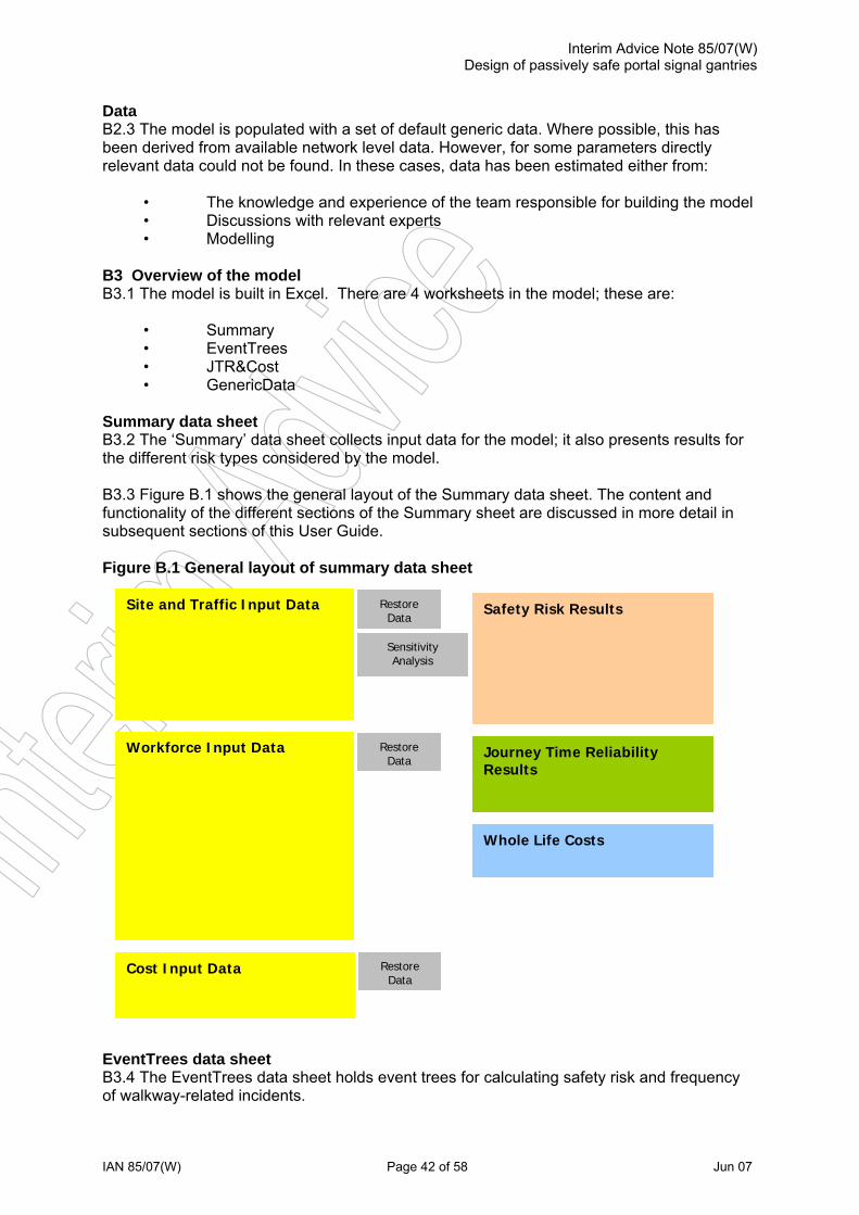
Interim Advice Note 85/07(W) Design of passively safe portal signal gantries
IAN 85/07(W) Page 42 of 58 Jun 07
Data B2.3 The model is populated with a set of default generic data. Where possible, this has been derived from available network level data. However, for some parameters directly relevant data could not be found. In these cases, data has been estimated either from:
• The knowledge and experience of the team responsible for building the model • Discussions with relevant experts • Modelling
B3 Overview of the model B3.1 The model is built in Excel. There are 4 worksheets in the model; these are:
• Summary • EventTrees • JTR&Cost • GenericData
Summary data sheet B3.2 The ‘Summary’ data sheet collects input data for the model; it also presents results for the different risk types considered by the model. B3.3 Figure B.1 shows the general layout of the Summary data sheet. The content and functionality of the different sections of the Summary sheet are discussed in more detail in subsequent sections of this User Guide. Figure B.1 General layout of summary data sheet
Safety Risk Results Site and Traffic Input Data Restore Data
Sensitivity Analysis
Workforce Input Data Restore Data
Journey Time Reliability Results
Whole Life Costs
Cost Input Data Restore Data
EventTrees data sheet B3.4 The EventTrees data sheet holds event trees for calculating safety risk and frequency of walkway-related incidents.

Interim Advice Note 85/07(W) Design of passively safe portal signal gantries
IAN 85/07(W) Page 43 of 58 Jun 07
B3.5 Users are not required to do anything with this sheet. It shows the detail of the safety risk calculation to inform sensitivity analyses and the understanding of what is driving safety risk. JTR&Cost data sheet B3.6 The JTR&Cost sheet calculates the Journey Time Reliability (JTR) impacts of different gantry types; it also calculates their whole life costs. B3.7 Users are not required to do anything with this sheet. It draws data from the ‘Summary’ and ‘GenericData’ sheets to perform calculations. The sheet then shows the detail of the JTR and WLC calculations to inform sensitivity analyses and the understanding of what is driving journey time reliability impact and whole life costs. GenericData data sheet B3.8 The GenericData sheet holds several types of data:
• Conditional probability data for safety risk event tees • Other frequency data for safety risk event trees • Consequence data for safety and Journey Time Reliability
Data on this sheet can be changed if designers feel the default data is not appropriate for their site or design. Hazards included in the model B4.1 Table B.1 describes the hazards and related event trees included within the model: Table B.1 Model hazards and related event trees
User Hazard Event Tree Operative and/or TM vehicle hit in TM (construction)
Operative hit behind protective barrier during construction
Gantry leg Road Restraint System
Gantry leg hit by errant vehicle
Occupant(s) of errant vehicle
Operative and/or TM vehicle hit in TM (operation)
Operative and/or TM vehicle in TM
Collapse of gantry onto the carriageway following impact Debris from vehicle impact
Other road users hit accident debris
Items dropped on the carriageway (operatives)
Operative on walkway/platform
Items dropped/thrown onto the carriageway (unauthorised access)
Unauthorised access by third party
Other road users
Items fall off gantry (as a result of unobserved deterioration/defects)
Object falls off gantry
Installing and removing TM (construction)
Operative hit crossing carriageway during construction
Working adjacent to live carriageway (construction)
Operative hit behind protective barrier during construction
Working at height (construction) Operative falls from height during construction
Installing and removing Traffic Management (Operation)
Operative hit crossing carriageway + Operative and/or TM vehicle hit in TM
Working at height on gantry walkway (Operation)
Operative on walkway/platform
Working at height on mobile platform (Operation)
Operative on walkway/platform + Operative and/or TM vehicle hit in TM
Operatives
Working adjacent to live traffic (operation)
Operative accident caused by errant vehicle
3rd Parties Fall from height (unauthorised access) Unauthorised access by third party

Interim Advice Note 85/07(W) Design of passively safe portal signal gantries
IAN 85/07(W) Page 44 of 58 Jun 07
B5 Description of input data B5.1 This section describes the input data required by the model. B5.2 Data can be input via yellow cells within the ‘Summary’ and ‘GenericData’ sheets. These cells are populated initially with default data, taken from network average data/estimates. However, data in these cells can be changed to reflect uncertainties/variability in data values for local sites or schemes. B5.3 To help determine whether the default data is appropriate, each yellow cell has a ‘comment’ attached to it which gives the basis for the default data value. ‘Comments’ can be viewed by positioning the cursor over the cell. Site and traffic input data B5.4 Table B.2 describes the site and traffic input data parameters. Site and traffic data is input via the ‘Summary’ data sheet. Table B.2 Site and traffic data parameters
Parameter Description Standard gantry design to include a walkway?
Select ‘yes’ or ‘no’ from the drop-down menu to set the baseline BD51 gantry design that the PSG will be compared with
Length of site within hitting distance of gantry leg
Length of carriageway in advance of gantry over which it is considered feasible that an errant vehicle could reach a gantry leg
Length of barrier in relation to above site length
Length of barrier to be provided at the site within the ‘length of site within hitting distance’. Note this length cannot be greater than the ‘length of site within hitting distance’.
Type of barrier Select from ‘None’, ‘N2’, ‘H1’ or ‘H4a’ Average frequency that vehicles leave carriageway
Average frequency of errant vehicles at the site expressed as the number of vehicles per 1km site length per year
Average frequency of unauthorised access to gantry (with or without a walkway)
Number of times per 10 year period per gantry that expect someone to attempt to climb a gantry (enter zero if not an ‘at risk’ site)
Time between General Inspection Number of years between General Inspections of the gantry structure
Time between Principal Inspection Number of years between Principal Inspections of the gantry structure
Time between re-painting for Standard gantries (steel construction)
Number of years between re-painting for steel gantries
Mean time between critical structural defects on a gantry
Mean number of years before an object falls into the carriageway if a critical defect that is present on the gantry is not detected
Average traffic mix passing through site Average mix of cars, LGVs, buses/coaches and HGVs

Interim Advice Note 85/07(W) Design of passively safe portal signal gantries
IAN 85/07 Page 45 of 58 Jun 07
Workforce input data B5.5 Table B.3 describes the workforce data parameters. Workforce data is input via the ‘Summary’ data sheet. Table B.3: Workforce data parameters Parameter Description
Duration of TM Input duration of TM to allow construction work adjacent to the live carriageway Day, night or 24h? Select ‘day’, ‘night’ or ‘24h’ for whether the TM is in place during day (only), night (only) or 24 hours Hard shoulder closed? Select ‘yes’ or ‘no’ for whether TM to allow construction work adjacent to the live carriageway involves
closure of the hard shoulder No. of carriageway lanes closed Select ‘0’, ‘1’, ‘2’ or ‘3’ for number of carriageway lanes closed to allow construction work adjacent to
the live carriageway Duration of work Input number of hours workforce are present adjacent to the live carriageway during construction No. of times operative required to cross live carriageway
Input number of ‘operative crossings’ required to install advance warning signs for construction TM (e.g. 2 operatives required to make 3 crossings per sign for 6 advance warning signs = 2 x 3 x 6 = 36)
Working adjacent to live carriageway, during construction
No. of operatives Input average number of operatives working adjacent to the live carriageway at any time during construction
Duration of closure Input duration of road closure to allow installation of the gantry boom Day, night or 24h? Select ‘day’, ‘night’ or ‘24h’ for whether installation of the gantry occurs during the day, at night or over
a 24 hour period
Working at height installing boom, during construction
No. of operatives Input number of operatives working at height during installation of the gantry boom General Inspections per year Value calculated from input ‘Time between General Inspection’ Other events per year Input number of times per year ‘other’ work is expected to be required adjacent to the live carriageway
during normal operation. Number to include visits to any equipment mounted adjacent to the gantry e.g. fixed CCTV cameras and communications cabinets.
Total no. of events per year Value calculated from number of General Inspections per year, plus number of ‘other’ events per year Average duration of TM Input average duration of any TM required to allow work adjacent to the live carriageway during normal
operation Day, night or 24h? Select ‘day’, ‘night’ or ‘24h’ for whether average work event (and therefore TM) occurs during the day,
at night or at any time over a 24 hour period Hard shoulder closed? Select ‘yes’ or ‘no’ for whether average TM to allow work adjacent to the live carriageway during
normal operation involves closure of the hard shoulder No. of carriageway lanes closed Select ‘0’, ‘1’, ‘2’ or ‘3’ for average number of carriageway lanes closed per work event to allow work
adjacent to the live carriageway during normal operation Average duration of work Input average number of hours per work event that workforce are present adjacent to the live
carriageway during normal operation Average no. of times operative required to cross live carriageway
Input average number of ‘operative crossings’ required to install advance warning signs for TM per work event
Working adjacent to live carriageway, normal operation
Average no. of operatives Input average number of operatives working adjacent to the live carriageway per work event Working at height on Principal Inspections per year Value calculated from input ‘Time between Principal Inspection’

Interim Advice Note 85/07(W) Design of passively safe portal signal gantries
IAN 85/07 Page 46 of 58 Jun 07
Parameter Description Other events per year Input number of times per year ‘other’ work is expected to be required from the gantry walkway.
Number to include routine inspection and maintenance of signals and other gantry-mounted equipment, plus reactive repairs of signals and other gantry-mounted equipment.
Total no. of events per year Value calculated from number of Principal Inspections per year, plus number of ‘other’ events per year Day, night or 24h? Select ‘day’, ‘night’ or ‘24h’ for whether average work event occurs during the day, at night or at any
time over a 24 hour period Average duration of work Input average number of hours per work event that workforce are present on the gantry walkway
during normal operation
Standard gantry walkway, normal operation
No. of operatives Input average number of operatives working adjacent to the live carriageway per event Principal Inspections per year Value calculated from input ‘Time between Principal Inspection’ Other events per year Input number of times per year ‘other’ work is expected to be required from a mobile platform during
normal operation. Number to include routine inspection and maintenance of signals and other gantry-mounted equipment, plus reactive repairs of signals and other gantry-mounted equipment.
Total no. of events per year Value calculated from number of Principal Inspections per year, plus number of ‘other’ events per year Average duration of TM Input average duration of any TM required to allow working at height on a mobile platform during
normal operation Day, night or 24h? Select ‘day’, ‘night’ or ‘24h’ for whether average work event (and therefore TM) occurs during the day,
at night or at any time over a 24 hour period Hard shoulder closed? Select ‘yes’ or ‘no’ for whether average TM to allow work from a mobile platform during normal
operation involves closure of the hard shoulder No. of carriageway lanes closed Select ‘0’, ‘1’, ‘2’ or ‘3’ for average number of carriageway lanes closed per work event to allow work
from a mobile platform during normal operation Average duration of work Input average number of hours per work event that workforce are on or around a mobile platform, (i.e.
working with TM on a live carriageway) during normal operation Average no. of times operative required to cross live carriageway
Input average number of ‘operative crossings’ required to install advance warning signs for TM per work event
Working at height on mobile platform with TM, normal operation
Average no. of operatives Input average number of operatives working on or around a mobile platform (i.e. working with TM on a live carriageway) per work event
Events per year Value calculated from input ‘Time between re-painting for Standard gantries’ Average duration of TM Input average duration of any TM required to allow re-painting work during normal operation Day, night or 24hr? Select ‘day’, ‘night’ or ‘24h’ for whether average work event (and therefore TM) occurs during the day,
at night or at any time over a 24 hour period Hard shoulder closed? Select ‘yes’ or ‘no’ for whether average TM to allow re-painting work during normal operation involves
closure of the hard shoulder No. of carriageway lanes closed
Input average number of carriageway lanes closed per work event to allow work associated with re-painting during normal operation
Average duration of work Input average number of hours per work event that workforce are working adjacent to a live carriageway during normal operation
Standard gantry re-painting
Average no. of times operative required to cross live carriageway
Input average number of ‘operative crossings’ required to install advance warning signs for TM per work event

Interim Advice Note 85/07(W) Design of passively safe portal signal gantries
IAN 85/07 Page 47 of 58 Jun 07
Parameter Description Average no. of operatives Input average number of operatives working on re-painting and adjacent to the live carriageway per
work event per work event
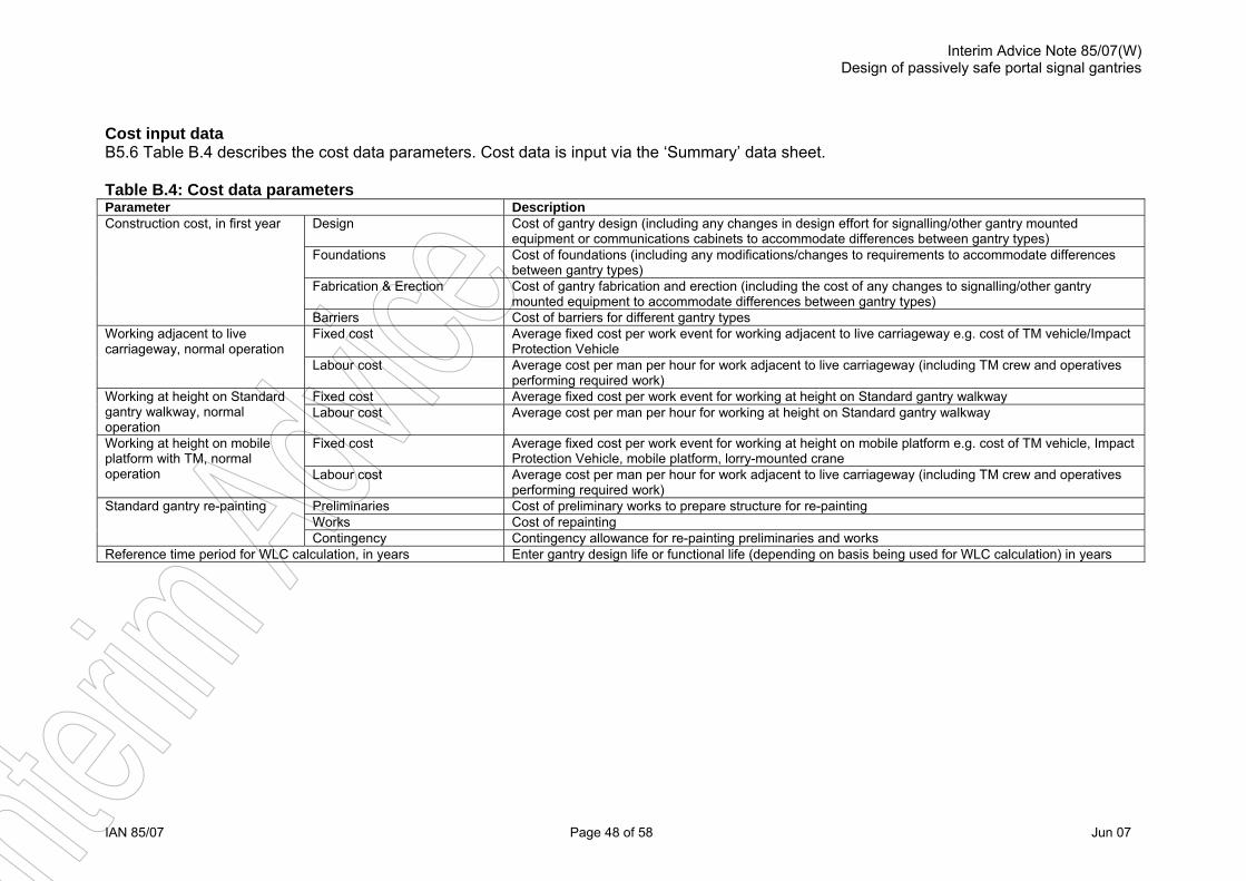
Interim Advice Note 85/07(W) Design of passively safe portal signal gantries
IAN 85/07 Page 48 of 58 Jun 07
Cost input data B5.6 Table B.4 describes the cost data parameters. Cost data is input via the ‘Summary’ data sheet. Table B.4: Cost data parameters Parameter Description
Design Cost of gantry design (including any changes in design effort for signalling/other gantry mounted equipment or communications cabinets to accommodate differences between gantry types)
Foundations Cost of foundations (including any modifications/changes to requirements to accommodate differences between gantry types)
Fabrication & Erection Cost of gantry fabrication and erection (including the cost of any changes to signalling/other gantry mounted equipment to accommodate differences between gantry types)
Construction cost, in first year
Barriers Cost of barriers for different gantry types Fixed cost Average fixed cost per work event for working adjacent to live carriageway e.g. cost of TM vehicle/Impact
Protection Vehicle Working adjacent to live carriageway, normal operation
Labour cost Average cost per man per hour for work adjacent to live carriageway (including TM crew and operatives performing required work)
Fixed cost Average fixed cost per work event for working at height on Standard gantry walkway Working at height on Standard gantry walkway, normal operation
Labour cost Average cost per man per hour for working at height on Standard gantry walkway
Fixed cost Average fixed cost per work event for working at height on mobile platform e.g. cost of TM vehicle, Impact Protection Vehicle, mobile platform, lorry-mounted crane
Working at height on mobile platform with TM, normal operation Labour cost Average cost per man per hour for work adjacent to live carriageway (including TM crew and operatives
performing required work) Preliminaries Cost of preliminary works to prepare structure for re-painting Works Cost of repainting
Standard gantry re-painting
Contingency Contingency allowance for re-painting preliminaries and works Reference time period for WLC calculation, in years Enter gantry design life or functional life (depending on basis being used for WLC calculation) in years

Interim Advice Note 85/07(W) Design of passively safe portal signal gantries
IAN 85/07 Page 49 of 58 Jun 07
Generic data B5.7 Generic data are held on the ‘GenericData’ data sheet. It is not expected that users will need to change default values for generic model data. Default values for the generic data are shown in Section B5.9. Sensitivity analysis B5.8 The Site and Traffic section of the ‘Summary’ data sheet includes scroll bars for sensitivity analysis. Moving these bars left or right increases or decreases the values for the relevant parameters. Effects of any changes made on model outputs are shown instantly in the results section. Restore data B5.9 The data input areas of the model include buttons that run macros, as follows:

Interim Advice Note 85/07(W) Design of passively safe portal signal gantries
IAN 85/07 Page 50 of 58 Jun 07
• Restore default site data. Loads in a default set of Site input data (the data displayed in Figure B.2).
Figure B.2 Default site and traffic input data
Site and Traffic Input DataStandard gantry design to include a walkway? no
Length of site within hitting distance of gantry leg, in metresPassively Safe 50
Standard 50Length of barrier in relation to above site length, in metres(enter zero if no barrier present)
Passively Safe 0Standard 30
Type of barrierPassively Safe none
Standard H1
Average frequency that vehicles leave carriageway 1.0(no. of vehicles per 1km site length per year)
Average frequency of unauthorised access to gantry (with or without a walkway)(no. of events per 10 year period per gantry, enter zero if not an at risk site)
Passively Safe 0.0Standard 0.0
Time between General Inspections, in yearsPassively Safe 2
Standard 2Time between Principal Inspections, in years
Passively Safe 6Standard 6
Time between re-painting for Standard gantries (steel construction), in years 15
Mean time between critical structural defects on a gantry, in years(Mean no. of years before object falls into carriageway if not detected)
Passively Safe 10.0Standard 10.0
Average traffic mix passing through siteCar 81%LGV 12%
Bus / Coach 1%HGV 6%

Interim Advice Note 85/07(W) Design of passively safe portal signal gantries
IAN 85/07 Page 51 of 58 Jun 07
• Restore default workforce data. Loads in a default set of Workforce input data (the
data displayed in Figure B.3). Figure B.3: Default workforce input data
Workforce Input DataWorking adjacent to live carriageway, during construction
Duration of TM, in hours 350 1350 1350Day, night or 24h? 24h 24h 24h
Hard shoulder closed? yes yes yesNo. of carriageway lanes closed 0 0 0
Duration of work, in hours 115 450 450No. of times operative required to cross live carriageway 30 30 30
No. of operatives 10 10 10Working at height installing boom (carriageway closed), during construction
Duration of closure, in hours 0.5 0.5 0.5Day, night or 24h? night night nightNo. of operatives 2 2 2
Working adjacent to live carriageway (routine I&M), normal operationGeneral Inspections per year (calculated from above) 0.5 0.5 0.5
Other events per year 2.5 2.5 2Total no. of events per year 3 3 2.5
Average duration of TM, in hours 0 0 0Day, night or 24h? day day day
Hard shoulder closed? no no noNo. of carriageway lanes closed 0 0 0
Average duration of work, in hours 1 1 1Average no. of times operative required to cross live carriageway, per event 0 0 0
Average no. of operatives 1 1 1Working at height on Standard gantry walkway, normal operation
Principal Inspections per year (calculated from above) 0 0.17Other events per year 0 5
Total no. of events per year 0 5.17Day, night or 24h? day day
Average duration of work, in hours 0 1No. of operatives 0 1
Working at height on mobile platform with TM, normal operationPrincipal Inspections per year (calculated from above) 0.17 0.17 0.00
Other events per year 5.5 5.5 0.5Total no. of events per year 5.67 5.67 0.50
Average duration of TM, in hours 7 7 7Day, night or 24h? night night night
Hard shoulder closed? yes yes yesNo. of carriageway lanes closed 2 2 2
Average duration of work, in hours 3 3 4Average no. of times operative required to cross live carriageway, per event 30 30 30
Average no. of operatives 3 3 3Standard gantry (steel construction) re-painting
Events per year (calculated from above) 0.07 0.07Average duration of TM, in hours 42 42
Day, night or 24h? night nightHard shoulder closed? yes yes
No. of carriageway lanes closed 3.33 3.33Average duration of work, in hours 42 42
Average no. of times operative required to cross live carriageway, per event 30 30Average no. of operatives 8 8
Passively Safe
Std. no walkway
Std. with walkway

Interim Advice Note 85/07(W) Design of passively safe portal signal gantries
IAN 85/07 Page 52 of 58 Jun 07
• Restore default cost data. Loads in a default set of Cost input data (the data displayed in Figure B.4).
Figure B.4: Default cost input data Cost Input DataConstruction cost, in first year
Design 10,000£ 10,000£ 10,000£ Foundations 10,000£ 40,000£ 40,000£
Fabrication & Erection 35,000£ 44,000£ 54,000£ Barriers -£ 70,000£ 70,000£
Working adjacent to live carriageway (routine I&M), normal operationFixed cost, £ per event 10£ 10£ 10£
Labour cost, £ per man hour 30£ 30£ 30£ Working at height on Standard gantry walkway, normal operation
Fixed cost, £ per event 0 10£ Labour cost, £ per man hour 0 30£
Working at height on mobile platform with TM, normal operationFixed cost, £ per event 100£ 100£ 100£
Labour cost, £ per man hour 30£ 30£ 30£ Standard gantry (steel construction) re-painting, per event
Preliminaries 16,000£ 16,000£ Works 55,000£ 55,000£
Contingency 9,000£ 9,000£
Reference time period for WLC calculation, in years 30 30 30
Passively Safe
Std. with walkway
Std. no walkway
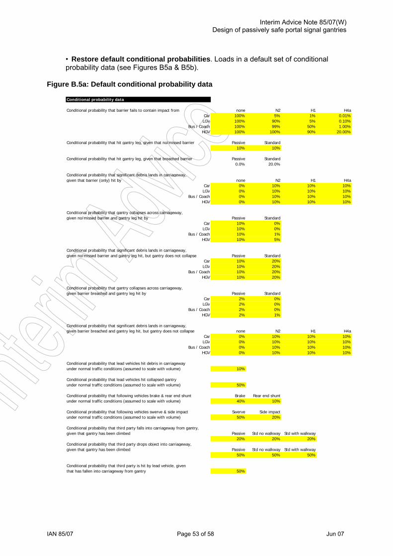
Interim Advice Note 85/07(W) Design of passively safe portal signal gantries
IAN 85/07 Page 53 of 58 Jun 07
• Restore default conditional probabilities. Loads in a default set of conditional probability data (see Figures B5a & B5b).
Figure B.5a: Default conditional probability data Conditional probability data
Conditional probability that barrier fails to contain impact from none N2 H1 H4aCar 100% 5% 1% 0.01%LGV 100% 90% 5% 0.10%
Bus / Coach 100% 99% 50% 1.00%HGV 100% 100% 90% 20.00%
Conditional probability that hit gantry leg, given that no/missed barrier Passive Standard10% 10%
Conditional probability that hit gantry leg, given that breached barrier Passive Standard0.0% 20.0%
Conditional probability that significant debris lands in carriageway,given that barrier (only) hit by none N2 H1 H4a
Car 0% 10% 10% 10%LGV 0% 10% 10% 10%
Bus / Coach 0% 10% 10% 10%HGV 0% 10% 10% 10%
Conditional probability that gantry collapses across carriageway,given no/missed barrier and gantry leg hit by Passive Standard
Car 10% 0%LGV 10% 0%
Bus / Coach 10% 1%HGV 10% 5%
Conditional probability that significant debris lands in carriageway,given no/missed barrier and gantry leg hit, but gantry does not collapse Passive Standard
Car 10% 20%LGV 10% 20%
Bus / Coach 10% 20%HGV 10% 20%
Conditional probability that gantry collapses across carriageway,given barrier breached and gantry leg hit by Passive Standard
Car 2% 0%LGV 2% 0%
Bus / Coach 2% 0%HGV 2% 1%
Conditional probability that significant debris lands in carriageway,given barrier breached and gantry leg hit, but gantry does not collapse none N2 H1 H4a
Car 0% 10% 10% 10%LGV 0% 10% 10% 10%
Bus / Coach 0% 10% 10% 10%HGV 0% 10% 10% 10%
Conditional probability that lead vehicles hit debris in carriageway As Modeledunder normal traffic conditions (assumed to scale with volume) 10% 10.00%
Conditional probability that lead vehicles hit collapsed gantry As Modeledunder normal traffic conditions (assumed to scale with volume) 50% 50.00%
Conditional probability that following vehicles brake & rear end shunt Brake Rear end shunt As Modeledunder normal traffic conditions (assumed to scale with volume) 40% 10% 4.00%
Conditional probability that following vehicles swerve & side impact Swerve Side impact As Modeledunder normal traffic conditions (assumed to scale with volume) 50% 20% 10.00%
Conditional probability that third party falls into carriageway from gantry,given that gantry has been climbed Passive Std no walkway Std with walkway Std as modelled
20% 20% 20% 20%Conditional probability that third party drops object into carriageway,given that gantry has been climbed Passive Std no walkway Std with walkway Std as modelled
50% 50% 50% 50%
Conditional probability that third party is hit by lead vehicle, giventhat has fallen into carria geway from gantry 50%

Interim Advice Note 85/07(W) Design of passively safe portal signal gantries
IAN 85/07 Page 54 of 58 Jun 07
Figure B.5b: Default conditional probability data (Continued)
Working adjacent to live carriageway, day night 24herrant vehicle rate factor for day, night, or 24h working 1.4 0.16 1.0
Conditional probability that operative(s) working adjacent to carriageway Passive Standardwhen errant vehicle leaves carriageway 0.034% 0.034%
Conditional probability that operative(s) hit, given that errant vehicle Passive Standardmissed barrier 10% 10%
Conditional probability that operative(s) hit, given that errant vehicle Passive Standardbreached barrier 0.0% 14.3%
Working on Standard walkway, day night 24herrant vehicle rate factor for day, night, or 24h working 1.4 0.16 1.0
Working on mobile platform, day night 24herrant vehicle rate factor for day, night, or 24h working 1.4 0.16 1.0
Conditional probability that operative falls into carriageway fromwalkway or platform walkway platform
0.000916% 0.0366%Conditional probability that operative drops significant objectinto carriageway from walkway or platform walkway platform
0.0073% 0.0018%Conditional probability that operative is hit by lead vehicle, giventhat has fallen into carriageway from walkway or platform walkway platform
50% 10%Conditional probability that General Inspection misses any critical defects present,per inspection performed
20%
Conditional probability that Principal Inspection misses any critical defects present,per inspection performed from walkway or platform walkway platform
5% 10%
Conditional probability that cursory inspection misses any critical defects present,per inspection performed from walkway or platform walkway platform
25% 50%
Conditional probability that operatives and/or TM vehicle present in TM whenerrant vehicle leaves carriageway Passive Standard
Working adjacent to live carriageway 0.00% 0.00%Platform 0.19% 0.23%
Conditional probability that operatives hit,given that errant vehicle breaches TM whilst operatives present Passive Standard
Working adjacent to live carriageway 10.0% 10.0%Platform 30.0% 30.0%
Conditional probability that TM vehicle hit,given that errant vehicle breaches TM whilst operatives present Passive Standard
Working adjacent to live carriageway 12.0% 12.0%Platform 12.0% 12.0%
Conditional probability that operative hit when crossing carriageway,per carriageway crossing 0.00002%
Working adjacent to live carriageway during construction, day night 24herrant vehicle rate factor for day, night, or 24h working 1.4 0.16 1.0
Conditional probability that operatives hit,given that errant vehicle breaches barrier during construction Passive Standard
100.0% 100.0%

Interim Advice Note 85/07(W) Design of passively safe portal signal gantries
IAN 85/07 Page 55 of 58 Jun 07
• Restore default consequences data. Loads in a default set of consequences data
(see Figure B6a & B6b). Figure B.6a: Default consequence
Event Tree Group AffectedGantry Leg Hit by Errant Vehicle Errant VehicleHit barrier & impact is contained No barrier N2 barrier H1 barrier H4a barrier
Car Several No Injury(ies) Several Minor Injury(ies) Several Major Injury(ies) Several Major Injury(ies)LGV One No Injury(ies) One Minor Injury(ies) One Major Injury(ies) One Major Injury(ies)
Bus / Coach Multiple No Injury(ies) Multiple Minor Injury(ies) Multiple Major Injury(ies) Multiple Major Injury(ies)HGV One No Injury(ies) One Minor Injury(ies) One Major Injury(ies) One Major Injury(ies)
Breach barrier & miss Passively Safe/Standard leg
Car Several Major Injury(ies) 0.30LGV One Major Injury(ies) 0.10
Bus / Coach Multiple Major Injury(ies) 1.00HGV One Major Injury(ies) 0.10
Breach barrier & hit Passively Safe legCar Several Major Injury(ies) 0.30LGV One Major Injury(ies) 0.10
Bus / Coach Multiple Major Injury(ies) 1.00HGV One Major Injury(ies) 0.10
Breach barrier & hit Standard legCar One Fatality(ies) 1.00LGV One Fatality(ies) 1.00
Bus / Coach One Fatality(ies) 1.00HGV One Fatality(ies) 1.00
Miss barrier & miss Passively Safe/Standard legCar Several Minor Injury(ies) 0.03LGV One Minor Injury(ies) 0.01
Bus / Coach Multiple Minor Injury(ies) 0.10HGV One Minor Injury(ies) 0.01
Miss barrier & hit Passively Safe legCar Several Minor Injury(ies) 0.03LGV One Minor Injury(ies) 0.01
Bus / Coach Multiple Minor Injury(ies) 0.10HGV One Minor Injury(ies) 0.01
Miss barrier & hit Standard legCar Several Fatality(ies) 3.00LGV One Fatality(ies) 1.00
Bus / Coach Multiple Fatality(ies) 10.00HGV One Fatality(ies) 1.00
Event Tree Group AffectedOther Road Users Hit Accident Debris Other Road Users As ModeledLead vehicles hit debris from barrier impact or gantry partial collapse
Lead veh. One Minor Injury(ies) 0.01Lead vehicles hit collapsed Passively Safe gantry on carriageway
Lead veh. Multiple Minor Injury(ies) 0.10Lead vehicles hit collapsed Standard gantry on carriageway
Lead veh. Multiple Major Injury(ies) 1.00Following vehicles brake & rear end shunt
Follow veh. Multiple Minor Injury(ies) 0.10Following vehicles swerve & side impact
Follow veh. Multiple Minor Injury(ies) 0.10
Event Tree Group AffectedOther Road Users Hit Dropped/Thrown/Fallen Object Other Road Users As ModeledLead vehicles hit object
Lead veh. One Minor Injury(ies) 0.01Following vehicles brake & rear end shunt
Follow veh. Multiple Minor Injury(ies) 0.10Following vehicles swerve & side impact
Follow veh. Multiple Minor Injury(ies) 0.10
Event Tree Group AffectedUnauthorised Third Party on Walkway/Platform Third Parties
Third party fallen into carriageway and hit by lead vehicleThird party One Fatality(ies) 1.00
Third party fallen into carriageway and missed by lead vehicleThird party One Major Injury(ies) 0.10
Event Tree Group AffectedOperative Accident Caused by Errant Vehicle Wokforce
Operative hit by errant vehicle (per operative hit)Workforce One Fatality(ies) 1.00
Event Tree Group AffectedOperative on walkway/platform Workforce
Operative fallen into carriageway and hit by lead vehicleWorkforce One Fatality(ies) 1.00
Operative fallen into carriageway and missed by lead vehicleWorkforce One Major Injury(ies) 0.10
Event Tree Group AffectedOperative and/or TM vehicle hit in TM / crossing carriageway Workforce, Errant Vehicle
Operative hit by vehicle (per operative hit)Workforce One Fatality(ies) 1.00
Errant vehicle hits TM vehicleCar Several Minor Injury(ies) 0.03LGV One Minor Injury(ies) 0.01
Bus / Coach Multiple Minor Injury(ies) 0.10HGV One Minor In jury(ies) 0.01

Interim Advice Note 85/07(W) Design of passively safe portal signal gantries
IAN 85/07 Page 56 of 58 Jun 07
Figure B.6b: Default consequence data (Continued) Emergency TM consequence data
Initial clearance of barrier impactPassively Safe 0.5 yes 2
Standard 0.5 yes 2Emergency roadworks to repair barrier
Passively Safe 3 yes 1Standard 3 yes 1
Removal of accident debris from carriagewayPassively Safe 0.5 no 2
Standard 0.5 no 2Removal of collapsed gantry from carriageway
Passively Safe 4 yes 3Standard 4 yes 3
Removal of dropped/thrown objects from carriagewayPassively Safe 0.5 no 2
Standard 0.5 no 2
Duration of TM, in hours
Hard shoulder closed?
No. of c.way lanes closed
B6 Model outputs and results B6.1 Outputs from the model are:
• Safety risk of different gantry designs (in units of Fatalities and Weighted Injuries/year)
• Journey Time Reliability impacts of different gantry designs (in units of Lost Lane Hours)
• Whole Life Costs of different gantry designs (as a discounted annual equivalent cost, in £)
The following sub-sections describe the outputs and results produced by the model in more detail. Safety risk results B6.2 Figure B.7 shows the format of the safety risk results, comparing a passively safe gantry with a standard BD51 gantry without walkway access:

Interim Advice Note 85/07(W) Design of passively safe portal signal gantries
IAN 85/07 Page 57 of 58 Jun 07
Figure B.7: Safety risk results Safety Risk:Fatalities + Weighted Injuries/ yr StandardOccupants of errant vehicles 1.36E-03 1.44E-02Other road users 3.04E-05 1.38E-05Workforce 7.56E-05 7.59E-05Third parties 0.00E+00 0.00E+00Total 1.46E-03 1.45E-02
Workforce risk during constructio
GreenSafety Risk for Passively Safe relative to Standard design
-90%
Passively Safe
n 1.29E-04 2.68E-04
Fatalities plus Weighted Injuries / year
0.0000
0.0020
0.0040
0.0060
0.0080
0.0100
0.0120
0.0140
0.0160
Passively Safe Standard
Occupants of errant vehicles Other road usersWorkforce Third parties
B6.3 Differences in safety risk between passively safe and standard gantries are presented in units of ‘Fatalities and Weighted Injuries/year’. Differences in safety risk are provided for:
• Workforce • Road users • Unauthorised Third Parties • Total
B6.4 The model shows the % difference in safety risk between Passively Safe and Standard gantries.
• If a Passively Safe gantry is >20% safer than a Standard gantry then Passively Safe gantry risk is rated as ‘Green’.
• If a Passively Safe gantry is >20% less safe than a Standard gantry then Passively Safe gantry risk rated as ‘Red’.
• For cases where Passively Safe gantry risk is within +/- 20% of Standard gantry risk then Passively Safety gantry risk is rated as ‘Amber’.
B6.5 The workforce safety risk associated with construction is also presented for Passively Safe and Standard gantries.

Interim Advice Note 85/07(W) Design of passively safe portal signal gantries
IAN 85/07 Page 58 of 58 Jun 07
B6.6 Safety risk results are also summarised in a graph that updates automatically as input data is changed. Journey time reliability results B6.7 Figure B.8 shows the format of the Journey Time Reliability results: Figure B.8: Journey time reliability results Journey Time Reliability:Lane Hours Lost / year StandardCarriageway, day 0.01 0.11Carriageway, night 79.33 88.67Hard shoulder, day 0.00 0.09Hard shoulder, night 39.67 42.48Total 119.01 131.35
Lane hours lost during construction 352.00 1,352.00
Passively Safe
B6.8 Journey Time Reliability impact is calculated in terms of ‘lane hours lost’ i.e. number of hours that lanes are closed because of planned or emergency Traffic Management associated with inspection, maintenance or repair of different gantry designs. B6.9 Lane hours lost are provided for:
• Carriageway, day • Carriageway, night • Hard shoulder, day • Hard shoulder, night • Total
The total lane hours lost during construction are also provided for different gantry designs. Whole-life cost results B6.10 Figure B.9 shows the format of the Whole Life Cost results (where ‘I&M’ is ‘Inspection & Maintenance’): Figure B.9: Whole-life cost results Whole life cost for constructionand routine I&M activities: Standard
Discounted annual equivalent cost £3,192 £8,417
Passively Safe
B6.11 The model calculates a discounted annual equivalent cost for different gantry designs. For each gantry, this is the total Present Value cost over the lifecycle, divided by the cycle duration. Within this, the model assumes a discount rate of 3.5%.