design of multi level car park using pre- cast/pre...
TRANSCRIPT

R. V. College of Engineering, Bengaluru-560059
(An Autonomous Institution affiliated to VTU, Belgavi)
Department of Civil Engineering
DESIGN OF MULTI LEVEL CAR PARK USING PRE-
CAST/PRE-STRESSED CONCRETE
PROJECT REPORT
Submitted by
NAME OF THE CANDIDATE USN
Uma Maheshwar Reddy S 1RV11CV036
Under the guidance of
Dr. Ravindra R. (Internal Guide)
Associate Professor,
Department of Civil Engineering, RV College Of Engineering, Bengaluru
&
Arjun M.V (External Guide)
General Manager,
TRC Engineering (I) PVT LTD., Bengaluru
In partial fulfilment for the award of degree
Bachelor of Engineering
in
Civil Engineering
2015

R.V. COLLEGE OF ENGINEERING, BENGALURU - 560059
(Autonomous Institution Affiliated to VTU, Belagavi)
DEPARTMENT OF CIVIL ENGINEERING
CERTIFICATE
Certified that the project work titled „Design of Multi-Level Car Park using Pre-Cast/Pre-
Stressed Concrete‟ is carried out by Uma Maheshwar Reddy (1RV11CV036) who is a
bonafide student of R.V College of Engineering, Bangalore, in partial fulfilment for the
award of degree of Bachelor of Engineering in Civil Engineering of the Visvesvaraya
Technological University, Belagavi during the year 2014-2015. It is certified that all
corrections/suggestions indicated for the internal assessment have been incorporated in the
report deposited in the departmental library. The project report has been approved as it
satisfies the academic requirements in respect of project work prescribed by the institution for
the said degree.
Signature of Guide Signature of Head of the Department Signature of Principal
External Viva
Name of Examiners Signature with date
1
2

R.V COLLEGE OF ENGINEERING, BENGALURU-560059
(Autonomous Institution Affiliated To VTU, Belagavi)
DEPARTMENT OF CIVIL ENGINEERING
DECLARATION
I, Uma Maheshwar Reddy S, the student of eighth semester B.E, Civil
Engineering, hereby declare that the project titled “DESIGN OF MULTI-
LEVEL CAR PARK USING PRE-CAST/PRE-STRESSED CONCRETE”
has been carried out by me and submitted in partial fulfilment for the award of
degree of Bachelor of Engineering in Civil Engineering. I do declare that this
work is not carried out by any other student for the award of degree in any other
branch.
Place: Bangalore Names Signature
Date: 1. Uma Maheshwar Reddy S

ACKNOWLEDGEMENT
I would like to express my deepest gratitude to my guide Dr. Ravindra R, Associate
Professor, faculty of Civil Engineering Department, RVCE, Bangalore for efficiently guiding
me throughout the project with his years of experience.
I would also like to express my deepest appreciation for my co-guide Mr Arjun M.V,
General Manager, TRC Engineering (I) PVT LTD. and Dr R. Ravindra, for their
invaluable guidance, advice, suggestions and encouragement, rendered at every stage in my
project work.
I would like to thank Mr. B.M Sagar for helping me in getting this internship.
I am grateful to Dr B.C. Udayashankar, Professor and Head, Department of Civil
Engineering, RVCE for encouraging the project.
I am grateful to our honourable Principal, Dr B.S.Satyanarayana for giving me the
permission to conduct this project.
I am deeply indebted to all the faculty members of Department of Civil Engineering, RVCE
for their knowledge advice and encouragement throughout the course of study.
Above all I wish to express my heartfelt thanks to the almighty GOD, for giving me an
opportunity to do this course.

DESIGN OF MULTI-LEVEL CAR PARK
ABSTRACT
With the rising number of vehicular population along with the city’s growth and rise in per
capita income, high volumes of vehicular traffic and congestion is presently the focus for
attention in most metropolitan cities across the world. A consequence to the inflation in the
traffic scenario, i.e. number of vehicles in cities & unplanned urbanization has led to
congestion. Hence, a decongestion programme backed by a systematic development plan in
basic infrastructure is required. One of the solutions to decongest roads and solve parking
problems is to adopt a multi‐level car parking system to maximise car parking capacity by
utilising vertical space, rather than expanding horizontally. Hence, in this project precast/pre-
stress concrete which are produced by casting concrete in a reusable mold and then cured in a
controlled environment, transported to the construction site and lifted into place using cranes
and connected using various connections for Structural Integrity has been adopted for
structurally designing a Multi-Level Car Park. This parking structure consists of four levels
of parking with two bays of ramp and is situated at Albany, New York. Except for the ground
floor, which is Cast in Situ, every other structural member used for the construction of the
building is made up of pre-cast/pre-stressed concrete.
The following methodology is adopted for this project. Firstly, the lateral loads and vertical
loads acting on the structure are assessed using STRUWARE Code Search. Then the
structure was modelled and analysed for lateral loads such as earthquake, wind loads, etc.
using ETABS. After the structure has satisfied the requirements for lateral loads, the gravity
load bearing members such as Double-Tee beams, Inverted-Tee beams, Spandrels, Columns
and Shear Walls are designed using PRESTO and VERTEX. Finally, the drawings are
prepared and assessed for conformity with accepted standards.
All the individual elements of the parking structure were successfully designed for lateral and
veertical forces and moments acting on them. Furthermore, the connections required to
develop the structural integrity of the parking garage were designed and analysed. Finally, the
parking garage was designed successfully conforming to accepted standards and deemed safe
for use for the purpose of parking vehicles.
Keywords: Precast concrete, Connections, Pre-stressed concrete, Lateral Analysis.

CONTENTS
List of Symbols, Abbreviations and Nomenclature i-ii
List of Tables iii-iv
List of Figures v-vii
Chapter-1 Introduction 01-08
1.1 Preamble. 01
1.2 Applications of Pre-Cast and Pre-Stressed Concrete. 02
1.1.1 Parking Structures 02
1.1.2 Bridges 03
1.1.3 Building Structures 03
1.3 Materials used in Pre-Cast and Pre-Stressed Concrete. 04
1.3.1 Cement 04
1.3.2 Concrete 04
1.3.3 Steel 04
1.4 Literature Review 05
1.5 Motivation 07
1.6 Objective 08
1.7 Methodology 08
1.8 Organisation of Dissertation. 08
Chapter-2 Theory and Fundamentals 09-22
2.1 Analysis of Pre-Cast/Pre-Stressed Structures 09
2.1.1 Gravity Loads 09
2.1.1.1 Dead Loads 09
2.1.1.2 Live Loads 09
2.1.1.3 Snow Loads 10
2.1.2 Lateral Loads 11
2.1.2.1 Wind Loads 11
2.1.2.1.1 ASCE 7-05[2] Method 11
2.1.2.2 Earthquake Loads. 13
2.1.2.2.1 Equivalent Lateral Force Method 14
2.2 Pre-Cast Products 18
2.2.1 Double Tee Beams 19
2.2.2 Spandrel Beams 19
2.2.3 Shear Walls 20
2.2.4 Columns 21
2.2.5 Inverted Tee Beams 21
2.3 Description of Parking Structure 22
Chapter-3 Objectives and Methodology 25-27
3.1 Objectives 25
3.2 Outlines of Methodology 25
3.3 Preparation of Design Criteria using STRUWARE Code Search 26
3.3.1 Codes & Standards 26
3.3.2 Expected Results from STRUWARE Code Search 26
3.4 Lateral Analysis of Structure using ETABS Software. 26
3.5 Overturning Analysis of Shear Wall. 27
3.6 Diaphragm Analysis. 27
3.7 Typical Connection Designs. 27
3.8 Gravity Analysis of Pre-Cast Components. 27
3.9 Preparation of Design Drawings. 27
Chapter-4 Lateral Analysis of Parking Garage 28-74
4.1 ETABS Output 30
4.2 Overturning Analysis 56
4.2.1 Tabulation of Results 56
4.2.2 Overturning Analysis for Walls in X-Direction. 58
4.2.2.1 PDL Calculation 59
4.2.2.2 Overturning Analysis 59
4.2.3 Overturning Analysis for Walls in Y-Direction. 60
4.2.3.1 Overturning Analysis for Shear Wall along Grid‘2’ 60
4.2.3.1.1 PDL Calculation. 61
4.2.3.1.2 Overturning Analysis. 62
4.2.3.1.3 Calculation of Reinforcement. 62
4.2.3.2 Overturning Analysis for Shear Wall along Grid‘4’ 63
4.2.3.2.1 PDL Calculation. 64
4.2.3.2.2 Overturning Analysis. 65
4.2.3.2.3 Calculation of Reinforcement. 65
4.3 Diaphragm Analysis 65

4.3.1 Tabulation of Results 66
4.3.2 Analysis 67
4.3.2.1 Diaphragm Analysis in N-S Direction 69
4.3.2.2 Diaphragm Analysis in E-W Direction. 70
4.3.2.2.1 Diaphragm Analysis (#1 & #2) 71
4.3.2.2.2 Diaphragm Analysis (#3 & #4) 73
Chapter-5 Design of Connections 75-85
5.1 Design of Foundation Connections 75
5.1.1 Design of Column Foundation Connection for Column 24’*34’ 75
5.1.2 Design of Shear Wall Foundation Connection 78
5.1.2.1 Design of Shear Wall Foundation Connection at Grid ‘2’ 78
5.1.2.2 Design of Shear Wall Foundation Connection at Grid ‘4’ 80
5.2 Design of Double-Tee Shear Wall Connection. 82
Chapter-6 Gravity Analysis of Pre-Cast/Pre-Stressed Components 86-117
6.1 Design of Double-Tee Beam Sections using Presto 86
6.1.1 Design of Double-Tee Beam Sections for End Conditions 86
6.1.2 Design of Double-Tee Beam Sections for Interior Conditions 90
6.2 Design of Inverted-Tee Beam Sections using Presto 95
6.2.1 Design of Inverted-Tee Beam Sections using Presto 95
6.3 Design of Spandrel Beam Sections using Presto 100
6.4 Design of Columns Sections using Vertex 103
6.5 Design of Shear Wall Sections using Vertex 106
6.6 Design of Lite Wall Sections using Vertex 111
Chapter-7 Conclusions 118
References 119-121
Annexures 122-127

DESIGN OF MULTI LEVEL CAR PARK
i
LIST OF SYMBOLS, ABBREVIATIONS AND NOMENCLATURES
AB : Area of base of structure, ft2
Ai : Web area of shear walls i, ft2
As : Tension Reinforcement, ft2.
b : Width of Design Section.
Cd : Deflection Amplification Factor.
Ce : exposure factor.
Cplee : Leeward Coefficient.
Cpwind : Windward Coefficient.
Cs : Seismic response coefficient.
Ct : Thermal factor.
CS : Seismic Response Coefficient
d : Depth to Flange Steel
Di : Length of shear wall i, ft.
Fa : Site Coefficient.
f'c : Concrete Strength. .
ft : Mesh Steel Yield Strength.
Fv : Site Coefficient.
G : Gust Effect Factor.
hi : Height of shear wall i, ft.
Ι : Importance factor.
Kd : Directionality Factor.
Kzt : Topographical Factor.
KZT : topographic factor.
Lc : Length of Cantilever
MOT : Over Turning Moment.
MR : Resisting Moment.
P : Concentrated Load.
Pg : Ground snow load, lb./ft2, from Design Aid 4.11.2, 4.11.3(a)[1], or as specified by local
authorities.
Ps : Combined windward and leeward net pressures.
Pf : Flat roof snow load, lb./ft2.
Ps30 : Wind pressure for exposure B at h = 30 ft.

DESIGN OF MULTI LEVEL CAR PARK
ii
qz : Velocity Pressure .
R : Response Modification Factor.
Ss : Mapped MCE Spectral Response Acceleration.
S1 : Mapped MCE Spectral Response Acceleration.
SMS : MCE Spectral Response Acceleration.
SM1 : MCE Spectral Response Acceleration.
SDS : Design Spectral Response Acceleration,
SD1 : Design Spectral Response Acceleration.
S : Distance between Stems.
tf : Thickness of Precast Flange.
Tl : Long-Period Transition Period.
V : Basic Wind Speed.
V : Seismic Base Shear.
Vu : Shear Force.
W : total dead load of structure.
WLL : Distributed Live Load.
WSL : Distributed Snow Load.
Wt : Weight of Precast Flange Concrete.
x : number of shear walls in the building effective in resisting lateral forces in the direction
under consideration.
zg : Gradient Height.
θ : Influence Angle
Φ : Strength Reduction Factor.
Ωo : System Overstrength Factor.
α : Empirical Exponent.
λ : Height and exposure adjustment factor.
DESIGN OF MULTI LEVEL CAR PARK
iii
LIST OF TABLES
Table 4.1 Load combination used for modelling...........................................................................29
Table 4.2 Story Data......................................................................................................................31
Table 4.3 Grid Systems................................................................................................................. 31
Table 4.4 Grid Lines......................................................................................................................32
Table 4.5 Material Properties - Summary..................................................................................... 32
Table 4.6 Frame Sections - Summary............................................................................................33
Table 4.7 Shell Sections - Summary..............................................................................................33
Table 4.8 Load Patterns.................................................................................................................34
Table 4.9 Auto Wind - ASCE 7-05 (Part 1 of 2)...........................................................................34
Table 4.10 Auto Wind - ASCE 7-05 (Part 1 of 2).........................................................................34
Table 4.11Applied Story Forces in X-Direction and Y-Direction................................................ 36
Table 4.12 Auto Seismic - ASCE 7-05 (Part 1 of 3)......................................................................37
Table 4.13 Auto Seismic - ASCE 7-05 (Part 2 of 3)......................................................................37
Table 4.14 Auto Seismic - ASCE 7-05 (Part 3 of 3)......................................................................38
Table 4.15 Calculated Base Shear along direction-X.....................................................................39
Table 4.16 Lateral Loads along direction-X..................................................................................40
Table 4.17 Calculated Base Shear along direction-Y.....................................................................42
Table 4.18 Lateral Loads along direction-Y..................................................................................43
Table 4.19 Calculated Base Shear along direction X+Ecc Y........................................................45
Table 4.20 Lateral Loads along direction-X + Ecc Y....................................................................46
Table 4.21 Calculated Base Shear along direction X - Ecc Y........................................................48
Table 4.22 Lateral Loads along direction-X -Ecc Y......................................................................49
Table 4.23 Calculated Base Shear along direction Y + Ecc X.......................................................51
Table 4.24 Lateral Loads along direction Y+Ecc X.......................................................................52
Table 4.25 Calculated Base Shear along direction Y - Ecc X........................................................54
Table 4.26 Lateral Loads along direction Y-Ecc X........................................................................55
Table 4.27 Shear Loads on lite wall P2..........................................................................................56
Table 4.28 Shear Loads on lite wall P3..........................................................................................56
Table 4.29 Shear Loads on shear wall P1......................................................................................56
Table 4.30 Shear Loads on shear wall P4......................................................................................57
Table 4.31 Lite Wall Lateral Foundation Forces...........................................................................57
Table 4.32 Shear Wall Lateral Foundation Forces.........................................................................57
DESIGN OF MULTI LEVEL CAR PARK
iv
Table 4.33 Story Shear for North-South Direction........................................................................66
Table 4.34 Story Shear for East-West Direction............................................................................67
Table 4.35 Comparisons between Lateral Analysis Story Shear and IBC Story Shear for N-S
Direction........................................................................................................................................68
Table 4.36 Comparisons between Lateral Analysis Story Shear and IBC Story Shear for E-W
Direction........................................................................................................................................68
Table 5.1 Strength of bolts and Threaded fasteners.......................................................................77
Table 5.2 Equivalent Area of Corresponding Steel Bars...............................................................81
Table 5.3 Shear Loads in kips for each Shear walls at Corresponding Floor Levels for Shear Wall
at grid ‘2’........................................................................................................................................82
Table 5.4 Shear Loads in kips for each Shear walls at Corresponding Floor Levels for Shear Wall
at grid ‘4’........................................................................................................................................82
Table 6.1 Shear forces for various Pier Labels..............................................................................96
Table 6.2 Reaction from DT stem on LB spandrel in Kips..........................................................101
Table 6.3 Loads in Klf..................................................................................................................101
Table 6.4 Loads and Moment on P1 and P2.................................................................................104

DESIGN OF MULTI LEVEL CAR PARK
v
LIST OF FIGURES
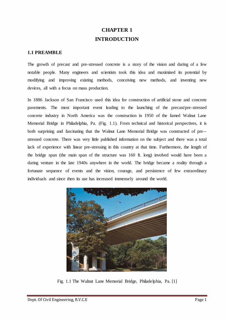
Fig. 1.1 The Walnut Lane Memorial Bridge, Philadelphia, Pa....................................................1
Fig. 1.2 A parking structure made completely of precast/pre-stressed concrete Bridge..............2
Fig. 1.3 Precast concrete proved to be a key element in completing the Arthur Ravenel Jr.
(Cooper River) Bridge in Charleston, S.C....................................................................................3
Fig. 1.4 Architectural precast concrete panels being used as load-bearing elements...................4
Fig. 2.1 Wind pressure zones on typical building elevations......................................................12
Fig. 2.2 Building Motion during an Earthquake..........................................................................13
Fig. 2.3 An isometric view of a building constructed with Pre-Casted product..........................18
Fig. 2.4 Pre-Cast double Tee beams............................................................................................19
Fig. 2.5 A typical L- Shaped spandrel beam................................................................................20
Fig. 2.6 A Pre Cast Spandrel Beam.............................................................................................20
Fig. 2.7 A Typical Shear wall......................................................................................................20
Fig. 2.8 Columns Pocketed with Corbels.....................................................................................21
Fig. 2.9 An Inverted T-Beam.......................................................................................................22
Fig. 2.10 3-D view of the Parking Garage...................................................................................22
Fig. 2.11 Plan of the Garage at Level-2.......................................................................................23
Fig. 2.12 Elevation Along Grid ‘B’.............................................................................................23
Fig. 2.13 Elevation Along Grid ‘2’..............................................................................................24
Fig. 3.1 Methodology of Work....................................................................................................27
Fig. 4.1 Isometric view of the Howard Street Parking Garage....................................................30
Fig. 4.2 Applied forces along direction-X...................................................................................36
Fig. 4.3 Applied forces along direction-X...................................................................................36
Fig. 4.4 Lateral Load in X- Direction…………………………………………………………..40
Fig. 4.5 Lateral Loads along direction-Y.....................................................................................43
Fig. 4.6 Lateral Loads along direction-X + Ecc Y.......................................................................46
Fig. 4.7 Lateral Loads along direction-X - Ecc Y........................................................................49
Fig. 4.8 Lateral Loads along direction Y + Ecc X.......................................................................52
Fig. 4.9 Lateral Loads along direction Y - Ecc X........................................................................55
Fig. 4.10 Elevation of Litewalls..................................................................................................58
Fig. 4.11 Plan of Litewalls..........................................................................................................59
Fig. 4.12 Plan of Shear Wall………...........................................................................................60
Fig. 4.13 Elevation of Shear Wall...............................................................................................61

DESIGN OF MULTI LEVEL CAR PARK
vi
Fig. 4.14 Elevation of Shear Wall................................................................................................63
Fig. 4.15 Plan of Shear Wall........................................................................................................64
Fig. 4.16 Plan of Diaphragm under consideration in N-S direction............................................69
Fig. 4.17 Bending Moment and Shear Force Diagrams for Diaphragm in N-S direction...........70
Fig. 4.18 Plan of Diaphragm (#1 & #2).......................................................................................71
Fig. 4.19 Bending Moment and Shear Force Diagrams for Diaphragm (#1 & #2) in E-W
direction…………........................................................................................................................72
Fig. 4.20 Plan of Diaphragm (#3 & #4).......................................................................................73
Fig. 4.21 Bending Moment and Shear Force Diagrams for Diaphragm (#3 & #4) in E-W
direction……………………………………………………………………………………........74
Fig. 5.1 Plan and Section of Column-Foundation Connection.....................................................76
Fig. 5.2 Section of Shear Wall-Foundation Connection..............................................................79
Fig. 5.3 Section of Double-Tee to Shear Wall Connection..........................................................83
Fig. 5.4 Embed Plate in Double-Tee............................................................................................84
Fig. 5.5 Embed Plate in Shear Wall.............................................................................................85
Fig. 5.6 Strap Plate for Insert.......................................................................................................85
Fig. 6.1 Load Distributions at the cantilever portion of the Double-Tee.....................................87
Fig. 6.2 Load Distributions at the stem portion of the Double-Tee.............................................88
Fig. 6.3 Load Distributions at the cantilever portion of the Double-Tee.....................................91
Fig. 6.4 Load Distributions at the stem portion of the Double-Tee.............................................93
Fig. 6.5 ITB Load Layout............................................................................................................95
Fig. 6.6 C/S at A-A......................................................................................................................95
Fig. 6.7 Ledge of Inverted-Tee Beam…………………………………………………………..97
Fig. 6.8 Loads acting on the Spandrel………………………………………………………….100
Fig. 6.9 C/S of the given spandrel..............................................................................................100
Fig. 6.10 Loading Diagram........................................................................................................103
Fig. 6.11 Section A-A................................................................................................................103
Fig. 6.12 Cross Section of Column............................................................................................104
Fig. 6.13 Shear Wall along Grid B2 and B4...............................................................................107
Fig. 6.14 12” Shear Wall............................................................................................................108
Fig. 6.15 Line Diagram of Column, h=5’...................................................................................109
Fig. 6.16 Lite Wall Elevation for LW's along grids 'B' between grids '3' and '4'........................112
Fig. 6.17 Line Diagram of Column, h=6’...................................................................................113

DESIGN OF MULTI LEVEL CAR PARK
vii
Fig. 6.18 Line Diagram of Column, h=6’....................................................................................115
Fig. 6.19 Line Diagram of Column, h=6’....................................................................................116
Design of Multi Level Car Park
Dept. Of Civil Engineering, R.V.C.E Page 1
CHAPTER 1
INTRODUCTION
1.1 PREAMBLE
The growth of precast and pre-stressed concrete is a story of the vision and daring of a few
notable people. Many engineers and scientists took this idea and maximized its potential by
modifying and improving existing methods, conceiving new methods, and inventing new
devices, all with a focus on mass production.
In 1886 Jackson of San Francisco used this idea for construction of artificial stone and concrete
pavements. The most important event leading to the launching of the precast/pre-stressed
concrete industry in North America was the construction in 1950 of the famed Walnut Lane
Memorial Bridge in Philadelphia, Pa. (Fig. 1.1). From technical and historical perspectives, it is
both surprising and fascinating that the Walnut Lane Memorial Bridge was constructed of pre--
stressed concrete. There was very little published information on the subject and there was a total
lack of experience with linear pre-stressing in this country at that time. Furthermore, the length of
the bridge span (the main span of the structure was 160 ft. long) involved would have been a
daring venture in the late 1940s anywhere in the world. The bridge became a reality through a
fortunate sequence of events and the vision, courage, and persistence of few extraordinary
individuals and since then its use has increased immensely around the world.
Fig. 1.1 The Walnut Lane Memorial Bridge, Philadelphia, Pa. [1]

Design of Multi Level Car Park
Dept. Of Civil Engineering, R.V.C.E Page 2
The 1950s were the years that brought into focus the seven-wire strand, long-line beds,
admixtures, high-strength concrete, vacuum concrete, steam curing, and many other innovations.
With these developments, coupled with the technical and logistical support the industry grew,
and the applications of precast and prestressed concrete began to appear in an impressive variety
of structures.
1.2 APPLICATIONS OF PRE-CAST AND PRE-STRESSED CONCRETES
Pre-cast and pre-stressed concrete have tremendous scope for application in the construction
industry and their usage is only going to proliferate with time. Some of the applications of pre-
cast and pre-stressed concrete is given below.
1.2.1 Parking Structures
Architects, engineers, developers, and owners have made precast and prestressed concrete the
material of choice for their commercial, municipal, and institutional parking needs. Though
classified and constructed as buildings, parking structures are unique; in some ways, they may be
compared with bridges with multiple decks. They are subjected to moving loads from automobile
traffic, and the roof level of a parking structure is exposed to weather in much the same way as a
bridge deck. They are subjected to moving loads from automobile traffic. In addition, they are
usually open-air structures and, thus, the entire structure is subjected to ambient weather
conditions, hence it requires special consideration of durability to ensure long-term performance.
An example of a parking structure is shown in Fig. 2.
Fig. 1.2 A parking structure made completely of precast/pre-stressed concrete [1]

Design of Multi Level Car Park
Dept. Of Civil Engineering, R.V.C.E Page 3
1.2.2 Bridges
Bridge construction gave the pre-stressing industry its start in North America. Precast and pre-
stressed concrete is now the dominant structural material for short- to medium-span bridges.
With its inherent durability, low maintenance, performance, and assured quality, precast and pre-
stressed concrete is a natural product for bridge construction. The ability to quickly erect precast
concrete components in all types of weather with little disruption of traffic adds to the economy
of the project. Fig 1.3. Is an example of pre-cast concrete being used as a vital element in the
construction of Arthur Ravenel Jr. (Cooper River) Bridge in Charleston.
Fig. 1.3 Precast concrete proved to be a key element in completing the Arthur Ravenel Jr.
(Cooper River) Bridge in Charleston, S.C.[1]
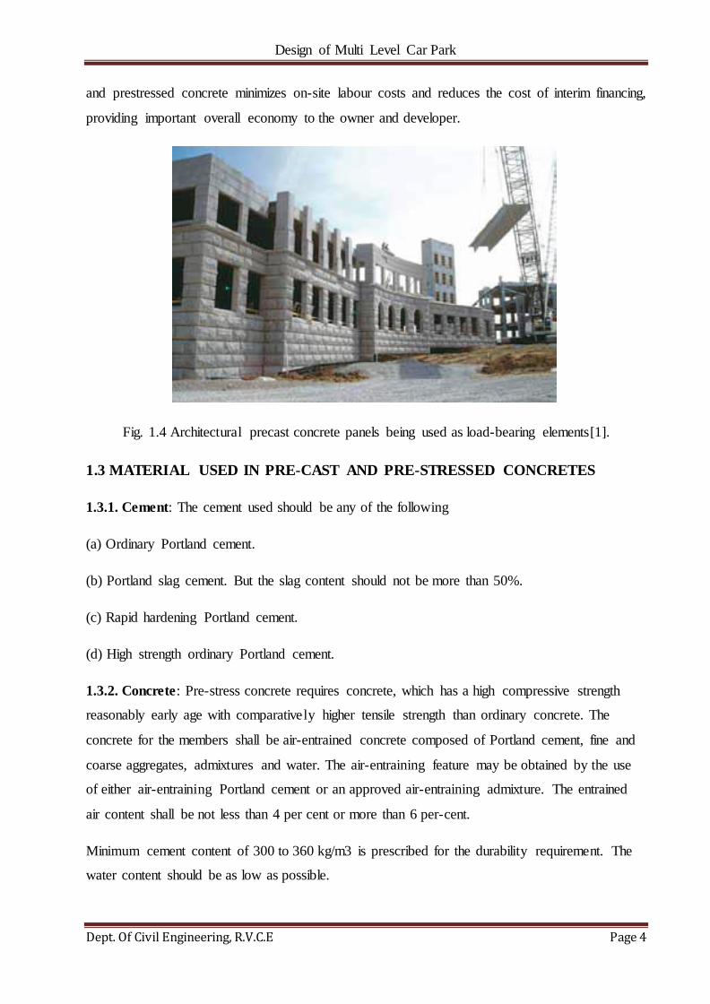
1.2.3 Building Structures
Owners, developers, and designers recognize the many inherent qualities of precast and pre-
stressed concrete that make it suitable for many types of building structures. Precast and pre-
stressed concrete building structures, assembled from high-quality, plant-produced products,
provide superior flexibility for achieving the required degrees of fire resistance, sound control,
energy efficiency, sustainability, and durability. The availability of various materials and finishes
makes it possible to render almost any desired aesthetic character and hence is used for
architectural works as shown in Fig. 1.4. The speed of construction that is possible with precast
Design of Multi Level Car Park
Dept. Of Civil Engineering, R.V.C.E Page 4
and prestressed concrete minimizes on-site labour costs and reduces the cost of interim financing,
providing important overall economy to the owner and developer.
Fig. 1.4 Architectural precast concrete panels being used as load-bearing elements[1].
1.3 MATERIAL USED IN PRE-CAST AND PRE-STRESSED CONCRETES
1.3.1. Cement: The cement used should be any of the following
(a) Ordinary Portland cement.
(b) Portland slag cement. But the slag content should not be more than 50%.
(c) Rapid hardening Portland cement.
(d) High strength ordinary Portland cement.
1.3.2. Concrete: Pre-stress concrete requires concrete, which has a high compressive strength
reasonably early age with comparatively higher tensile strength than ordinary concrete. The
concrete for the members shall be air-entrained concrete composed of Portland cement, fine and
coarse aggregates, admixtures and water. The air-entraining feature may be obtained by the use
of either air-entraining Portland cement or an approved air-entraining admixture. The entrained
air content shall be not less than 4 per cent or more than 6 per-cent.
Minimum cement content of 300 to 360 kg/m3 is prescribed for the durability requirement. The
water content should be as low as possible.
Design of Multi Level Car Park
Dept. Of Civil Engineering, R.V.C.E Page 5
1.3.3. Steel:-Few types of steel used are high tensile steel, tendons, strands and cables.
The steel used in pre-stress shall be any one of the following:-
(a) Plain hard-drawn steel wire
(b) Cold drawn indented wire
(c) High tensile steel wire bar
(d) Uncoated stress relived strand
High strength steel contains:
0.7 to 0.8% carbons,
0.6% manganese,
0.1% silica
1.4 LITERATURE REVIEW
Lepech et al.[2] discusses the problems arising in the construction industry relating to
sustainability and deterioration of the environment. He has developed a cradle-to-cradle mindset
where infrastructure systems can be designed, built, operated, maintained, reconfigured, and
recycled in a highly sustainable fashion. Through adoption of an integrated design framework for
sustainable infrastructure, durable prefabricated elements can become an important element of
highly sustainable infrastructure systems. Furthermore Lepech et al. discusses the importance of
pre-cast concrete and extols its merits.
Kaar et al. [3] investigated the development of continuity in precast, prestressed concrete bridge
girders used in conventional designs for extending span lengths. The conventional design used
deformed reinforcement in the CIP deck slab over the girders to provide continuity designed for
resisting the live loads. Kaar et al. [3] carried out tests on the connection detail where the
deformed rebar in the deck slab is made continuous over the supports and resists the negative
bending moment. This detail also included the use of a diaphragm over the piers extending
laterally between the girders on either side. The width of the diaphragms was greater than the
spacing between the ends of the girders, which helped to provide lateral restraint to strengthen
the concrete in compression. The results from this study found that this continuity connection
detail was desirable as it permits sufficient redistribution of moment and is simple to construct
and relatively economical.

Design of Multi Level Car Park
Dept. Of Civil Engineering, R.V.C.E Page 6
Mirmiran et al.[4] conducted a research study on positive moment cracking in the diaphragms of
simple-span prestressed girders made continuous. This study was aimed atinvestigating precast
bridge girders that can be made continuous for live loads by providing a moment connection over
the supports. The researchers achieved this by placing negative moment reinforcement in a CIP
deck over the support and by placing a diaphragm between the girder ends. The study also
recommended that ―a minimum amount of positive moment reinforcement equivalent to 1.2Mcr‖
should be used to limit the crack width in the diaphragm and to avoid significant loss of
continuity, where Mcr is the cracking moment of the diaphragm section.
Mattock [5] conducted a study to investigate the accuracy of the fps equation given in ACI 318-
77[6], and proposed an equation, which is currently being used by ACI 318-02[7] and the
AASHTO Standard Specifications, to estimate the stress in the prestressing steel at ultimate
capacity. Mattock related the limit on the maximum amount of tensile steel to the stress in the
prestressing strand at ultimate load and stated that the limit of 0.30 on the reinforcing index is a
good approximation to the point of fps=fpy for low concrete strengths. However, the reinforcing
index corresponding to fps=fpy decreases significantly as the concrete strength increases. Based
on these results, the new limit on the reinforcing index was proposed to be 0.36β1, instead of
0.30. In the 1983 edition of ACI Code (ACI, 1983)[6], the limiting value of 0.30 in ACI 318-
77[6] was changed to 0.36β1 ―so as to account for the effect of increase in concrete strength.
Ronald[8] highlighted the use of a post-tensioning splicing system coupled with high
performance concrete to build longer spans ranging up to 320 ft in Florida. This article focused
on the various factors to be accounted for in the analysis, design, and construction of prestressed,
post-tensioned bulb-tee girders. In this design approach, the bulb-tee girders were precast, pre-
tensioned, and then spliced using post-tensioning performed in two stages on the construction
site. Two types of spliced post-tensioned systems using haunched girder segments over the piers
were discussed in this article. The precast, prestressed bulb-tee girders fabricated in short
segment lengths were spliced on the construction site. Stage 1 post-tensioning allowed for girders
to become continuous before casting of the deck. Stage 2 post-tensioning resulted in residual
compression in the deck for serviceability and deflection control. The two-stage system of post-
tensioning allowed for wider spacing between the girders, and the higher cost of posttensioning
was compensated for by a reduction in the number of piers. The proposed system did not use
intermediate diaphragms. Because lateral stability became an important issue for long and
slender girders, it was recommended to use sections with wide top and bottom flanges. Creep and
shrinkage significantly affect the stress and deflection in continuous composite prestressed

Design of Multi Level Car Park
Dept. Of Civil Engineering, R.V.C.E Page 7
concrete members; therefore, the use of the ultimate creep and shrinkage coefficients in the
analysis was found to be critical. It was recommended to use the coefficients obtained from
previous projects or mix design testing and adjust the girder fabrication and construction
schedules to alleviate the time-dependent effects. The construction process for this spliced
structural system was found to be simple and cost-effective compared to span-by-span and
balanced cantilever construction.
Ng Ban Kiong et al [9]. discuss the factors that will lead to maintenance issues for building using
precast concrete system. These factors will be those that need to be considered at the design,
manufacturing and construction stage for the precast concrete system. Lastly, they also propose
recommendations to be used by designers, contractors, manufacturers and researchers who are
involved in precast concrete system.
A report put forth to the Karnataka government by KSIIDC-IL&FS Project Development
Company (KIPDC)[10], delineates the problems faced due to on road parking as detailed further.
High population density, large number of pavement hawkers, sidewalk encroachments,
heterogeneous nature of traffic and commercial area development along all the major roads have
compounded the problem of congestion on the main as well as internal roads of these cities.
Since there is no planned parking space available within these cities, currently, the city traffic
police allow parking of passenger vehicles on the side of the road thereby eating away a sizeable
portion of motorable road. The precious time of citizens is wasted due to traffic jams and if this
problem is not solved at this stage, and then it would become a serious and complicated problem
in future. Multi‐level parking lots at strategic places and a rational parking fee are inevitable for
solving the problem of finding parking space for the growing number of vehicles.
Jack P. Moehle et al.[11] provides explicit details for the analysis of diaphragm. Furthermore, the
functions of the diaphragm are delineated and different methods of analysis are provided
depending on the state and condition of the diaphragm.
1.5 MOTIVATION
Regular method of in-situ construction is prone to a number of problems such as wastage of
materials, difficulty in controlling the construction phase, susceptibility to large deflections and
cracks due to shrinkage and creep, etc. It has been found that the use of pre-stressed concrete can
negate these drawbacks and offer several other advantages such as improved quality control,
acoustic control, thermal efficiency, etc. Hence, an attempt is made to implement the concept of

Design of Multi Level Car Park
Dept. Of Civil Engineering, R.V.C.E Page 8
pre-stress concrete in the construction of large structures to improve the efficiency of the
construction process.
1.6 OBJECTIVE
The main objective of this project is to understand and implement the concepts of Pre-stressed
and pre-cast concrete in the design of a Multi-Level Car Park for lateral loads (seismic, wind,
etc.), vertical loads (dead load, live load, self-weight, etc.) and design of connections.
1.7 METHODOLOGY
Firstly the plan and the elevation of the parking structure is obtained from the Engineer of Record
(EOR) and the seismic, wind, snow, etc. data is collected pertaining to the location of the parking
structure using a software called STRUWARE code search. After which, the data collected is
used in modelling the parking structure for lateral analysis using ETABS. Then, various
connections were designed for the purpose of connecting various pre-cast elements so as to
achieve structural integrity. Finally, each component is designed for vertical/gravity loads using
PRESTO for horizontal elements and VERTEX for vertical elements.
1.8 ORGANIZATION OF THE DISSERTATION
In this report, in chapter 1 an introduction and history of pre-cast/pre-stressed industry is
delineated. Chapter 2 provides an in-depth explanation of the methods involved in the analysis,
different pre-cast/pre-stressed elements used and the description of the parking structure which is
to be designed. Chapter 3 outlines the methodology adopted in carrying out the project. Chapter 4
contains information regarding lateral analysis of the structure of ETABS which includes
overturning analysis of shear walls and diaphragm analysis. Chapter 5 and Chapter 6 contain
information regarding the design of connections and individual pre-cast elements respectively.
Chapter 8 presents the conclusions of the project and finally the references and annexures are
provided.
***
Design of Multi Level Car Park
Dept. Of Civil Engineering, R.V.C.E Page 9
CHAPTER 2
THEORY AND FUNDAMENTALS
2.1 ANALYSIS OF PRE-CAST/PRE-STRESSED STRUCTRES.
Pre-cast and pre-stressed structures are analysed for various loads such as gravity loads and
lateral loads which are as follows-
1. Gravity Loads
a. Dead Loads
b. Live Loads
c. Snow Loads
2. Lateral Loads
a. Wind Loads
b. Earthquake Loads
2.1.1 GRAVITY LOADS
Gravity loads are generally both live loads and dead loads whose main component is the vertical
force acting on the structure. Typical vertical loads include dead load of the structure, live loads,
loads due to fixed machinery in the building and snow loads. Vertical loads vary in intensity
depending on the type of building, structural materials, height and shape.
2.1.1.1 DEAD LOADS
Dead loads include the self-weight of the structural components plus any materials or elements
that are attached to or permanently in place on the component or assembly. Since the dead loads
are presumed to be determinable with a reasonable degree of accuracy, the load factor by ASCE
7-05[13] is 1.2 when combined with live loads. The ultimate factored load, however, may not be
less than 1.4D when live loads are low.
2.1.1.2 LIVE LOADS
Live loads are considered variable, transient, and not accurately determinable, so the load factor
is higher and is equal to 1.6. In some cases, a maximum live load may be calculated with a high
degree of accuracy (for example, fluid pressure), and a lower load factor is then used.

Design of Multi Level Car Park
Dept. Of Civil Engineering, R.V.C.E Page 10
2.1.1.3 SNOW LOADS
Snow loads are treated differently from other live loads by ASCE 7-05[13] because they are very
transient and vary by geographical location and terrain. The basic snow load for flat roofs is
determined by:
Pf= 0.7CeCtΙPg … (2.1)
Limited by:
Pf≥ ΙpgwherePg≤ 20 lb/ft2
Pf≥ 20Ι where Pg> 20 lb/ft2
where:
Pf= flat roof snow load, lb/ft2
Ce= exposure factor from Design Aid 4.11.3(b)[A1]
Ct= thermal factor from Design Aid 4.11.3(c)[A1]
Ι = importance factor from Design Aid 4.11.1[A2]
Pg= ground snow load, lb/ft2, from Design Aid 4.11.2, 4.11.3(a)[A1], or as
specified by local authorities.
2.1.2 LATERAL LOADS
Most lateral loads are live loads whose main component is horizontal force acting on the
structure. Typical lateral loads would be a wind load against a facade, an earthquake, the wave
pressure against a beach front retaining wall or the earth pressure against a basement wall. Most
lateral loads vary in intensity depending on the building's geographic location, structural
materials, height and shape. The dynamic effects of wind and earthquake loads are usually
analysed as an equivalent static load in most small and moderate-sized buildings. Others must
utilize the iterative potential of the computer.
2.1.2.1 WIND LOADS
The most common lateral load is a wind load. The Eiffel Tower is one example of a building
which has a structure that was designed to resist a high wind load. Wind against a building builds

Design of Multi Level Car Park
Dept. Of Civil Engineering, R.V.C.E Page 11
up a positive pressure on the windward side and a negative pressure (or suction) on the leeward
side. Depending upon the shape of the structure it may also cause a negative pressure on the side
walls or even the roof. The pressure on the walls and roof is not uniform, but varies across the
surface. Winds can apply loads to structures from unexpected directions. Thus, a designer must
be well aware of the dangers implied by this lateral load. The magnitude of the pressure that acts
upon the surfaces is proportional to the square of the wind speed.
There are 3 methods of determining wind loads as per ASCE 7-05[13]:-
Method 1 – Simplified procedure
Method 2 – Analytical procedure
Method 3 – Wind tunnel procedure
In this project only Method 1 is used for the analysis and design for wind loads.
2.1.2.1.1 ASCE 7-05[13] – METHOD 1 FOR WIND DESIGN
The limitations on structures for which this method can be used are generally as follows:
1. Height ≤ 60 ft. or least lateral dimension.
2. Enclosed building (includes parking structures).
3. Regular shaped.
4. No expansion joints.
5. Fundamental frequency H ≤ 1 Hz. (Nearly all concrete buildings under 60 ft. will qualify.)
6. Flat or shallow pitched roof.
The following illustrates the procedures required for this simplified analysis:
1. Determine the basic wind speed from Design Aid 4.11.5[A3].
2. Determine the importance factor Ι from Design Aid 4.11.1[A2].
3. Determine the exposure category that applies to upwind direction.
• Exposure B: Urban and suburban areas, wooded areas
• Exposure D: Flat, unobstructed areas outside hurricane-prone regions

Design of Multi Level Car Park
Dept. Of Civil Engineering, R.V.C.E Page 12
• Exposure C: All others
4. Determine the pressure zones on each side of the building from Fig. 3.1.
5. Determine the height and exposure adjustment factor λ from Design Aid 4.11.6(c)[A4].
6. Determine topographic factor KZT from ASCE 7-05[13].
7. Determine the ps30 forces for each zone from Design Aid 4.11.6(a)[A4].
Fig. 2.1 Wind pressure zones on typical building elevations.[1]
8. The pressure on the MWFRS for each zone is then determined from:
Ps= λKZTΙPs30 … (2.2)
,where:
Ps= combined windward and leeward net pressures
λ = height and exposure adjustment factor
Ι = importance factor
KZT = topographic factor as defined in Section 6.5.7 of ASCE 7-05[13].
Ps30 = wind pressure for exposure B at h = 30 ft.
9. The force on the MWFRS is then determined by multiplying the values of Ps by their
respective zone areas.
ZONE A ZONE B
Width of zone A = the lesser of 20% of the least dimension of the building, or 80% of
the mean roof height, but not less than 8% of the least dimension of the building, or 6 ft. Zone A can be on either end, depending on wind direction.

Design of Multi Level Car Park
Dept. Of Civil Engineering, R.V.C.E Page 13
2.1.2.2 EARTHQUAKE LOADS
Earthquakes generate horizontal and vertical ground movement. When the seismic waves pass
beneath a structure, the foundation will tend to move with the ground, while the superstructure
will tend to remain in its original position. The lag between foundation and superstructure
movement will cause distortions and develop forces in the structure. As the ground moves,
changing distortions and forces are produced throughout the height of the structure. The current
philosophy for the design of earthquake-resistant structures permits minor damage for moderate
earthquakes and accepts major damage for severe earthquakes, provided that the possibility of
complete collapse is minimized. The design details often require large, inelastic deformations to
occur in order to absorb the inertial forces. This is achieved by providing component and
connection ductility. While this ductility can prevent total collapse, the resultant distortions may
lead to significant damage to mechanical, electrical, and architectural elements. Seismic damage
can be minimized by setting limitations on structural deflections, such as interstory drift.
Fig. 2.2 Building Motion during an Earthquake

Design of Multi Level Car Park
Dept. Of Civil Engineering, R.V.C.E Page 14
The response of a structure to the ground motion of an earthquake depends on the structural
system with its damping characteristics and on the distribution of its mass. With mathematical
idealization, a designer can determine the probable response of the structure to an imposed
earthquake. ASCE 7-05[13] requires a dynamic analysis for structures that have highly irregular
shapes or framing systems, or are particularly tall in seismic design categories D, E, and F. While
ASCE 7-05[13] allows a dynamic analysis for other structures, most precast buildings are not tall
and have structural systems and shapes that are more or less regular. Most designers use the
equivalent static force method for these structures.
Different methods of analysing a structure for earthquake loads are as follows:-
1) Time-History Analysis
2) Response Spectrum Analysis
3) Equivalent Lateral Force Method
In this project, only Equivalent Lateral Force Method is adopted and hence, and effort is made to
explain the above mentioned method in detail.
2.1.2.2.1 EQUIVALENT LATERAL FORCE METHOD
The procedure described is applicable to all buildings in seismic design categories B, C, and to
most precast concrete structures in D, E, and F. This method may not apply to buildings with
irregularities in seismic design categories D, E, or F, depending on the nature of the irregularity.
The seismic base shear V in a given direction is determined by:
V = Cs*W … (2.3)
Where:
Cs= seismic response coefficient
W = total dead load of structure plus:
• 25% of floor live load in storage areas (live load in parking structures
not included).
• If partition load is included in gravity load, include the actual partition
weight or a minimum weight of 10 lb./ft2, whichever is greater.

Design of Multi Level Car Park
Dept. Of Civil Engineering, R.V.C.E Page 15
• Total weight of permanent operating equipment.
• 20% of flat-roof snow load where snow load exceeds 30 lb./ft2.
The seismic response coefficient Cs is proportional to the design-response spectrum. The design-
response spectrum has two segments: a short-period plateau and a descending curve with lower
values for longer building periods. Two coefficients, SS and S1, define these two segments, and
they vary with geographical location. Maps of the United States showing contours for SS and S1
are provided in ASCE 7-05[2] and in IBC 2006[4].
To determine Cs:
1. Determine SS and S1 from the map or from local building codes.
2. Determine site classification from soil reports or Design Aid 4.11.7(a)[A5]. If site soils are not
known, use site class D.
3. Calculate response accelerations:
SMS= FaSS … (2.4)
SM1 = FvS1 … (2.5)
Where:
Fa and Fvre site coefficients from Design Aid 4.11.7(b) and
(c)[A5].
4. Calculate the 5% damped design-spectral-response accelerations:
SDS= )SMS … (2.6)
SD1 = (2/3)SM1 … (2.7)
To= (0.2)SD1/ SDS … (2.8)
Ts= SD1/ SDS … (2.9)
5. Determine the seismic design category from Table 4.2.1 of PCI Handbook [1]. This will
sometimes restrict the type of seismic-force-resisting system (SFRS) used.
6. Determine the fundamental period of the building from:

Design of Multi Level Car Park
Dept. Of Civil Engineering, R.V.C.E Page 16
Ta = Cthnx … (2.10)
Where:
Ct = 0.016 for moment-resisting-frame systems of reinforced
concrete in which the frames resist 100% of the required seismic
forces and are not enclosed or adjoined by more rigid components
that prevent that frame from deflecting when subjected to seismic
forces
= 0.020 for other concrete structural systems
hn = distance from base to highest level, ft.
x = 0.9 for concrete moment-resisting frames
= 0.75 for other concrete structural systems
For shear-wall structures, the approximate fundamental period may also be determined from:
√ … (2.11)
Where
∑
(
)
… (2.12)
And
AB= area of base of structure, ft2
Ai = web area of shear walls i, ft2
Di = length of shear wall i, ft.
hi= height of shear wall i, ft.
x = number of shear walls in the building effective in resisting
lateral forces in the direction under consideration.
Design of Multi Level Car Park
Dept. Of Civil Engineering, R.V.C.E Page 17
When designing the lateral-force-resisting system for strength, the period used for the calculation
for the base shear may not exceed the approximate period by more than a factor Cu, which
depends on SD1. The coefficient Cu can be determined from Table 4.2.2 in PCI Handbook [1].
Linear interpolation is permitted for values of SD1 between the values in the table. For shear-wall
buildings, the design period factor may be applied to the longer period value of (2.11) or (2.12).
However, as noted above, the period shall not be taken greater than:
Tmax= CuTa … (2.13)
Cu is found from Table 4.2.2 in PCI Handbook [1].
7. Determine Cs from the lesser of Eq. 2-15 and 2-16 (or 2-17):
Cs= SDS /(R / I) … (2.14)
Where:
R = response modification factor from Design Aid 4.11.8[A6]
I = importance factor from Design Aid 4.11.1[A2]
Cs= SDS /(R / I) for T ≤ TL … (2.15)
Cs = SD1TL/{T2(R / I)}for T >TL … (2.16)
Where:
TL= long-period transition period ASCE 7-05[2]
But cannot be less than:
Cs = 0.044SDSΙ ≥ 0.01 … (2.17)
In addition, for structures located where S1 ≥ 0.6g, Cs cannot be less than:
Cs= 0.5S1/(R / I) … (2.18)
The base shear determined by (2.4) is a function of Cs, which is calculated using (2.15) to (2.19).
Each of these equations has the term R, the response modification coefficient, which is a function
of the lateral-force-resisting system and is provided in Design Aid 4.11.8[A6]. In many cases,
engineering judgement is required to assign the appropriate R. Systems with walls that carry most
Design of Multi Level Car Park
Dept. Of Civil Engineering, R.V.C.E Page 18
of the gravity loads (bearing-wall systems) get lower R factors than systems where structural
walls essentially brace complete gravity frames. This reflects the concern for additional safety
where structural elements that are resisting lateral forces also support gravity loads. Where there
is a gravity system that is independent of the shear walls, but some of the shear walls directly
carry vertical loads to the foundation, the engineer must determine if this creates a bearing-wall
system, or if the building may be defined as a building-frame system that uses shear walls for
lateral-load resistance with the same walls incidentally sharing in part of the vertical support.
Such a system with ordinary, reinforced-concrete shear walls is assigned an R of 5. The
distinction is an important one, because the difference in the R values that are assigned results in
11.1% more lateral load for the bearing-wall system. If the shear walls are truly incidental to the
vertical load frame, then the higher R value is appropriate. It is possible to have different values
of R in two orthogonal directions of the same structure.
2.2 PRE-CAST/PRE-STRESSED PRODUCTS
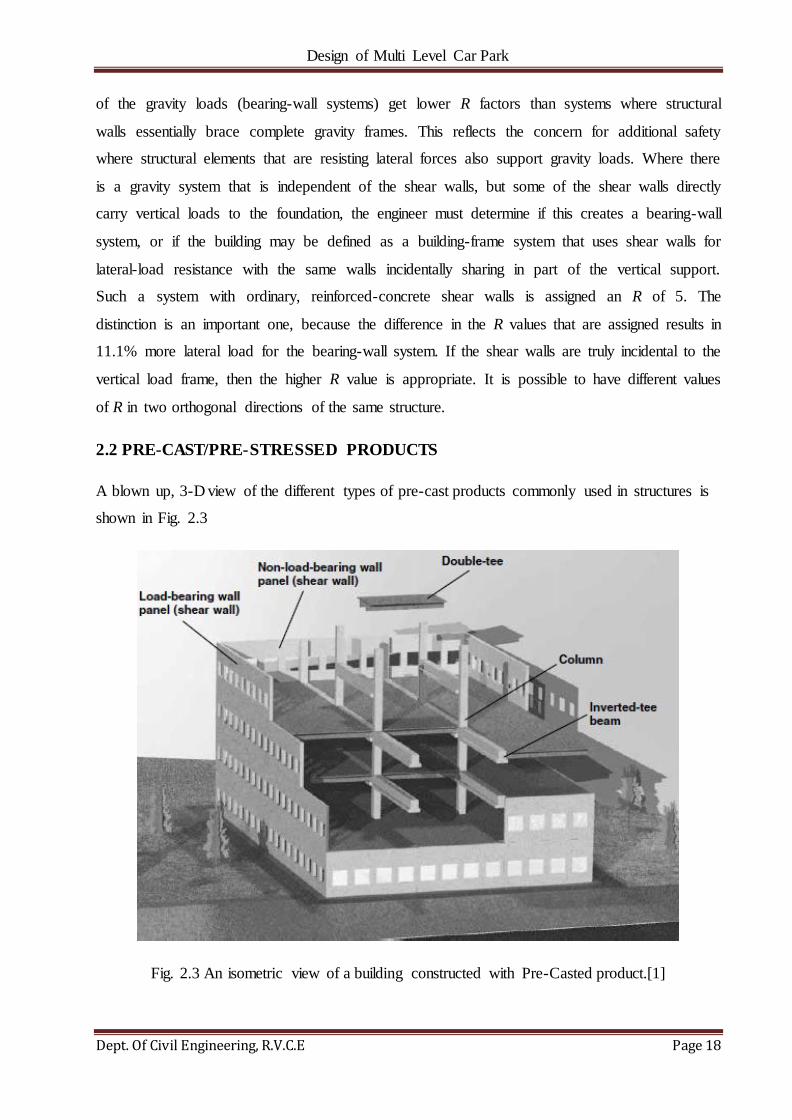
A blown up, 3-D view of the different types of pre-cast products commonly used in structures is
shown in Fig. 2.3
Fig. 2.3 An isometric view of a building constructed with Pre-Casted product.[1]
Design of Multi Level Car Park
Dept. Of Civil Engineering, R.V.C.E Page 19
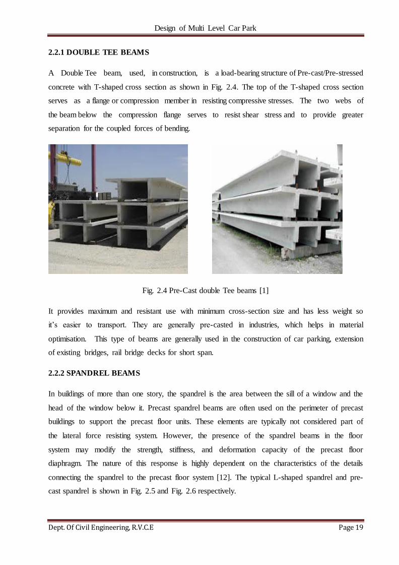
2.2.1 DOUBLE TEE BEAMS
A Double Tee beam, used, in construction, is a load-bearing structure of Pre-cast/Pre-stressed
concrete with T-shaped cross section as shown in Fig. 2.4. The top of the T-shaped cross section
serves as a flange or compression member in resisting compressive stresses. The two webs of
the beam below the compression flange serves to resist shear stress and to provide greater
separation for the coupled forces of bending.
Fig. 2.4 Pre-Cast double Tee beams [1]
It provides maximum and resistant use with minimum cross-section size and has less weight so
it‘s easier to transport. They are generally pre-casted in industries, which helps in material
optimisation. This type of beams are generally used in the construction of car parking, extension
of existing bridges, rail bridge decks for short span.
2.2.2 SPANDREL BEAMS
In buildings of more than one story, the spandrel is the area between the sill of a window and the
head of the window below it. Precast spandrel beams are often used on the perimeter of precast
buildings to support the precast floor units. These elements are typically not considered part of
the lateral force resisting system. However, the presence of the spandrel beams in the floor
system may modify the strength, stiffness, and deformation capacity of the precast floor
diaphragm. The nature of this response is highly dependent on the characteristics of the details
connecting the spandrel to the precast floor system [12]. The typical L-shaped spandrel and pre-
cast spandrel is shown in Fig. 2.5 and Fig. 2.6 respectively.

Design of Multi Level Car Park
Dept. Of Civil Engineering, R.V.C.E Page 20
Fig. 2.5 A typical L- Shaped spandrel beam Fig. 2.6 A Pre Cast Spandrel Beam [1]
2.2.3 SHEAR WALL
In structural engineering, a shear wall is a structural system composed of braced panels (also
known as shear panels) to counter the effects of lateral load acting on a structure. Wind and
seismic loads are the most common loads that shear walls are designed to carry. Shear walls are
vertical elements of the horizontal force resisting system. When shear walls are designed and
constructed properly, they will have the strength and stiffness to resist the horizontal forces. (Fig.
2.7)
Fig. 2.7 A typical Shear wall
Shear walls should be located on each level of the structure including the crawl space. To form
an effective box structure, equal length shear walls should be placed symmetrically on all four
exterior walls of the building. Shear walls should be added to the building interior when the
Design of Multi Level Car Park
Dept. Of Civil Engineering, R.V.C.E Page 21
exterior walls cannot provide sufficient strength and stiffness or when the allowable span-width
ratio for the floor or roof diaphragm is exceeded.
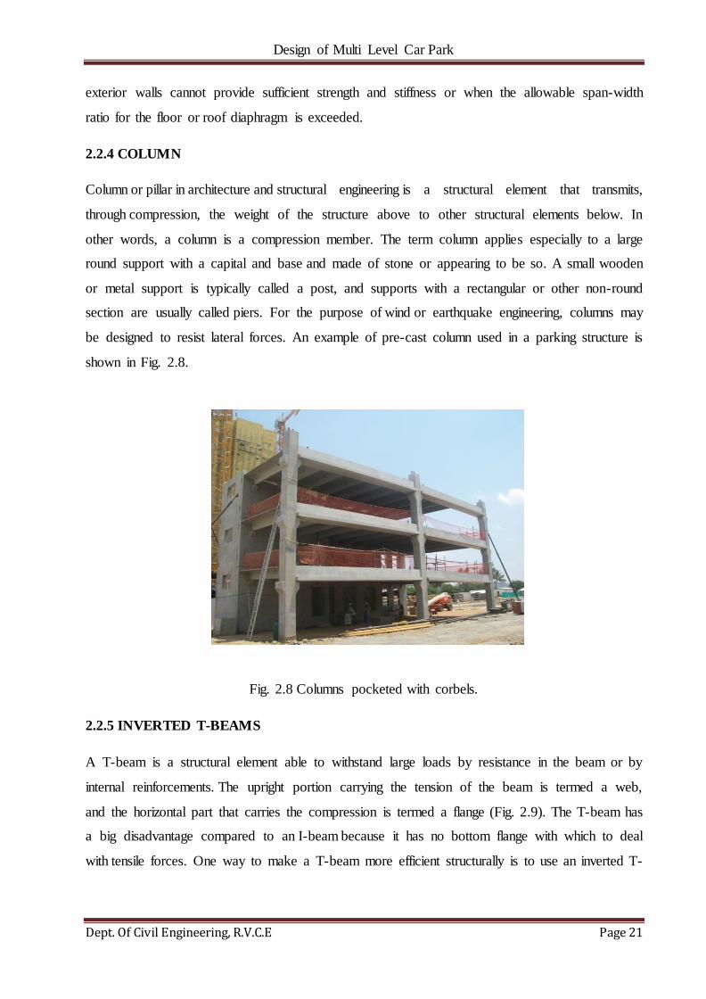
2.2.4 COLUMN
Column or pillar in architecture and structural engineering is a structural element that transmits,
through compression, the weight of the structure above to other structural elements below. In
other words, a column is a compression member. The term column applies especially to a large
round support with a capital and base and made of stone or appearing to be so. A small wooden
or metal support is typically called a post, and supports with a rectangular or other non-round
section are usually called piers. For the purpose of wind or earthquake engineering, columns may
be designed to resist lateral forces. An example of pre-cast column used in a parking structure is
shown in Fig. 2.8.
Fig. 2.8 Columns pocketed with corbels.
2.2.5 INVERTED T-BEAMS
A T-beam is a structural element able to withstand large loads by resistance in the beam or by
internal reinforcements. The upright portion carrying the tension of the beam is termed a web,
and the horizontal part that carries the compression is termed a flange (Fig. 2.9). The T-beam has
a big disadvantage compared to an I-beam because it has no bottom flange with which to deal
with tensile forces. One way to make a T-beam more efficient structurally is to use an inverted T-

Design of Multi Level Car Park
Dept. Of Civil Engineering, R.V.C.E Page 22
beam with a floor slab or bridge deck joining the tops of the beams. Done properly, the slab acts
as the compression flange.
Fig. 2.9 An Inverted T-Beam
2.3 DESCRIPTION OF PARKING STRUCTURE
The Structure comprises of 4 levels of Parking with 2 bays of Ramp. Apart from the ground floor
and foundation which is cast in place (CIP) all other floors are entirely comprised of pre-cast
elements. It is situated in Albany, New York, USA, the longitudinal coordinates and latitudinal
coordinates of the site is 42o 39’ 16” and 73o 46’ 32”, respectively. It comprises of a
compartment which consists of stair case and an elevator for convenience of the garage users
situated at the north-west and south-east corners of the building. The garage spans 177.6ft in
length, 125.6ft in breath and 57.3ft in height with a distance of 11ft between each floor. The plan
and various elevations are shown through Fig. 2.10-Fig 2.13.
Fig.2.10 3-D view of the Parking Garage.

Design of Multi Level Car Park
Dept. Of Civil Engineering, R.V.C.E Page 23
Following building elements were used for construction of the garage:
1. Double Tee Beams
2. Inverted Tee Beams
3. Spandrels
4. Column
5. Shear Walls
6. Lite Walls
Fig. 2.11 Plan of the Garage at Level-2
Fig. 2.12 Elevation Along Grid ‗B‘

Design of Multi Level Car Park
Dept. Of Civil Engineering, R.V.C.E Page 24
Fig. 2.13 Elevation Along Grid ‗2‘
***

Design of Multi Level Car Park
Dept. Of Civil Engineering, R.V.C.E Page 25
CHAPTER 3
OBJECTIVES AND METHODOLOGY
3.1 OBJECTIVES
1. To understand the concepts of Pre-stressed and pre-cast concrete.
2. To analyse and design a structure for lateral loads such as wind loads and seismic loads
and for vertical loads such as dead loads, live loads and snow loads.
3. To design connections so as to transfer load, restrain movement and provide stability.
3.2 OUTLINE OF METHODOLOGY
Fig. 3.1 Methodology of Work.
PREPARATION OF FINAL REPORT.
PREPARATION OF DESIGN DRAWINGS.
GRAVITY ANALYSIS OF PRECAST COMPONENTS.
TYPICAL CONNECTION DESIGNS.
DIAPHRAGM ANALYSIS.
OVERTURNING ANALYSIS OF SHEAR WALLS.
LATERAL ANALYSIS OF THE STRUCTURE USING ETABS SOFTWARE FROM CSI BERKELEY.
PREPARATION OF DESIGN CRITERIA USING STRUWARE CODE SEARCH PROGRAM

Design of Multi Level Car Park
Dept. Of Civil Engineering, R.V.C.E Page 26
3.3 PREPARATION OF DESIGN CRITERIA USING STRUWARE CODE
SEARCH PROGRAM
The loads are assessed and calculated based on the location and relevant codes involved using the
software Struware Code Search. The structure to be designed is located at Albany, New York and
thus, the software uses this information to assess the atmospheric and geological conditions
existing in the area such as seismic zones, wind speed, soil pressure, etc. along with relevant
building codes such as those mentioned in [3.3.1], etc. to calculate the final loads acting on the
building.
3.3.1 CODES AND STANDARDS
1. International Building Code (IBC) 2006 & 2010 New York State Code
2. Minimum Design Loads for Buildings and Other Structures-ASCE 7-05.
3. Building Code requirements of Structural Concrete-ACI 318-05.
4. PCI Design Handbook-Seventh Edition.
3.3.2 EXPECTED RESULTS FROM STRUWARE CODE SEARCH
1. Live Loads
2. Dead Loads
3. Wind Design Data
4. Roof Snow Loads
5. Earthquake Design Data
3.4 LATERAL ANALYSIS OF THE STRUCTURE USING ETABS.
The parking structure is modelled as per the drawings provided by the client for various lateral
loads such as earthquake loads and wind loads using ETABS. The loads acting on the shear walls
and lite walls are determined and are tabulated. These values are then used to carry out
overturning analysis of shear walls as well as diaphragm analysis for the purpose of determining
the stability and integrity of the structure against lateral forces.
Design of Multi Level Car Park
Dept. Of Civil Engineering, R.V.C.E Page 27
3.5 OVERTURNING ANALYSIS OF SHEAR WALLS.
Shear walls act as vertical cantilever beams, which transfer lateral forces acting parallel to the
face of the wall, from the superstructure to the foundation. Shear walls should be oriented to
resist lateral loads applied to the building along both principal axes of the building.
3.6 DIAPHRAGM ANALYSIS
Diaphragms transmit inertial forces from the floor system to the vertical elements of the seismic
force-resisting system. They also tie the vertical elements together and thereby stabilize and
transmit forces among these elements as may be required during earthquake shaking.
Diaphragms are thus an essential part of the seismic force-resisting system and require design
attention by the structural engineer to ensure the structural system performs adequately during
earthquake shaking. [11].
3.7 TYPICAL CONNECTION DESIGNS.
The design of connections is one of the most important considerations in the structural design of
a precast concrete structure. There are many successful solutions to each connection condition.
The purpose of a connection is to transfer load, restrain movement, and/or provide stability.
Within any one connection, there may be several load transfers; each one must be designed for
adequate strength and ductility and be appropriately detailed. The detailing should take into
account allowable tolerances, provide for a good fit between the selected materials, and avoid
interference between strand or reinforcing steel and the connection components, such as headed
concrete anchors or deformed bar anchors.
3.8 GRAVITY ANALYSIS OF PRECAST COMPONENTS.
Each pre-cast member is analyzed and designed according the dead loads, live loads, etc.
prescribed by relevant code books as mentioned in [3.3.1].
3.9 PREPARATION OF DESIGN DRAWINGS.
Sections of the pre-cast members as well as the plan and elevation of the car park are prepared
using AutoCADD.
***

Design of Multi Level Car Park
Dept. Of Civil Engineering, R.V.C.E Page 28
CHAPTER 4
LATERAL ANALYSIS OF THE PARKING GARAGE
Lateral Analysis for the was done using ―ETABS‖ software designed by Computers and
Structures Inc., CA, This program was used mainly to obtain values for the lateral forces resisted
by Lateral force resisting elements, i.e., the structural walls. The program assigns these forces to
the walls/frames based on their relative stiffness and their location within the structure using
mathematical models.
A (3-D) model was created graphically in the program and the structure was analysed for the
effects of wind and seismic forces in accordance with the International Building Code (IBC)
2006 [15] and ASCE 7-05 [13]– Minimum Design Loads for Buildings and Other Structures.
The structure contains 5 levels of parking with 2 bays of Ramps. The extent of Grids is Grid ‗1‘
to ‗5‘at North-South direction and Grids ‗A‘ to ‗C‘ at East-West Direction.
Following are some of the assumptions made to model the structure in ETABS:
1. 12‖ thick Shear walls along Grid ‗2‘ and Grid ‗4‘ of the Structure which are running for entire
height in Global ‗Y‘ (East-West) and 12‖ thick Lite Walls along Grid ‗B‘ which runs for the
entire height in Global ‗X‘ (North-South) directions respectively are considered to be the part of
Lateral resisting system.
2. Some of the walls in the structure were not used as part of the lateral system, however, they
were modelled in order to get the correct mass for the entire structure.
3. The floor members in the Parking area (15DT30s) in the model are assigned with 6.37‖
Thickness which gives it‘s correct self-weight of 79.625 psf.
4. Ramps are modelled ―flat‖ at its upper level in ETABS conservatively.
5. All of the Precast Floors/Roofs as mentioned above are modelled as ―Rigid Diaphragm‖ to
transfer the lateral forces to the lateral resisting elements.
6. The Response Factor, R = 4 for Lite walls & Shear walls.
7. The load combination which was used in modelling is given in Table 4.1 below.

Design of Multi Level Car Park
Dept. Of Civil Engineering, R.V.C.E Page 29
The program calculates and distributes all story shears to the lateral load resisting elements based
on the Stiffness‘s etc. The resulting Base Shears and Overturning Moments have been tabulated
for each of the lateral load resisting elements. The stability of the lateral loads resisting elements
was studied based on the output obtained.
A Quality Control Check was done to ensure that the program has calculated the correct seismic
weight and corresponding total base shear on the structure.
The load combinations used for modelling the structure is displayed in Table 4.1.
Table 4.1 Load combination used for modelling
Type of Load Multiplication Factor Referral Code Book
DL 1.2 ASCE 07-05[13]
LL 1.5 ASCE 07-05[13]
SL 0.2 ASCE 07-05[13]

Design of Multi Level Car Park
Dept. Of Civil Engineering, R.V.C.E Page 30
4.1 ETABS OUTPUT
Fig. 4.1 Isometric wireframe view of the Howard Street Parking Garage
ETABS OUTPUT
HOWARD STREET PG
MULTI LEVEL CAR PARK
Design of Multi Level Car Park
Dept. Of Civil Engineering, R.V.C.E Page 31
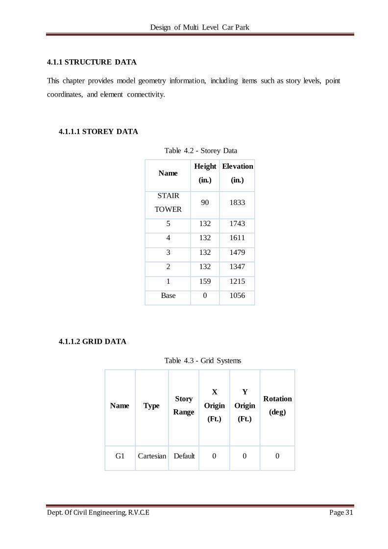
4.1.1 STRUCTURE DATA
This chapter provides model geometry information, including items such as story levels, point
coordinates, and element connectivity.
4.1.1.1 STOREY DATA
Table 4.2 - Storey Data
Name Height
(in.)
Elevation
(in.)
STAIR
TOWER 90 1833
5 132 1743
4 132 1611
3 132 1479
2 132 1347
1 159 1215
Base 0 1056
4.1.1.2 GRID DATA
Table 4.3 - Grid Systems
Name Type Story
Range
X
Origin
(Ft.)
Y
Origin
(Ft.)
Rotation
(deg)
G1 Cartesian Default 0 0 0

Design of Multi Level Car Park
Dept. Of Civil Engineering, R.V.C.E Page 32
Table 4.4 - Grid Lines
Grid
System
Grid
Direction Grid ID Visible
Ordinate
(Ft.)
G1 X 1 Yes 0
G1 X 1.2 Yes 11.17
G1 X 2 Yes 42
G1 X 3 Yes 87
G1 X 4 Yes 132
G1 X 4.5 Yes 153.33
G1 X 5 Yes 174
G1 Y C Yes 0
G1 Y C.4 Yes 20.67
G1 Y B Yes 59
G1 Y A.4 Yes 96.5
G1 Y A Yes 118
4.1.2 PROPERTIES
This chapter provides property information for materials, frame sections, shell sections, and
links.
4.1.2.1 MATERIALS
Table 4.5 - Material Properties - Summary
Name Type E
(lb./in²)
Unit
Weight
(lb./ft³)
Design Strengths
A615Gr60 Rebar 29000000 490 Fy=60000 lb./in²,
Fu=90000 lb./in²
PRECAST Concrete 4415201 150 Fc=6000 lb./in²

Design of Multi Level Car Park
Dept. Of Civil Engineering, R.V.C.E Page 33
4.1.2.2 FRAME SECTIONS
Table 4.6 - Frame Sections - Summary
Name Material Shape
10C10 PRECAST Concrete Rectangular
10SP132 PRECAST Concrete Rectangular
10SP159 PRECAST Concrete Rectangular
10SP52 PRECAST Concrete Rectangular
12SP84 PRECAST Concrete Rectangular
24C34 PRECAST Concrete Rectangular
32C34 PRECAST Concrete Rectangular
32IT36 PRECAST Concrete Rectangular
34C34 PRECAST Concrete Rectangular
48C34 PRECAST Concrete Rectangular
4.1.2.3 SHELL SECTIONS
Table 4.7 - Shell Sections - Summary
Name Design
Type
Element
Type Material
Total
Thickness
(in.)
15DT30 Slab Membrane PRECAST 6.37
16'' STAIRCASE
SLAB Slab Membrane PRECAST 16
LITE WALLS Wall Shell-Thin PRECAST 12
SHEAR WALL Wall Shell-Thin PRECAST 12
Design of Multi Level Car Park
Dept. Of Civil Engineering, R.V.C.E Page 34
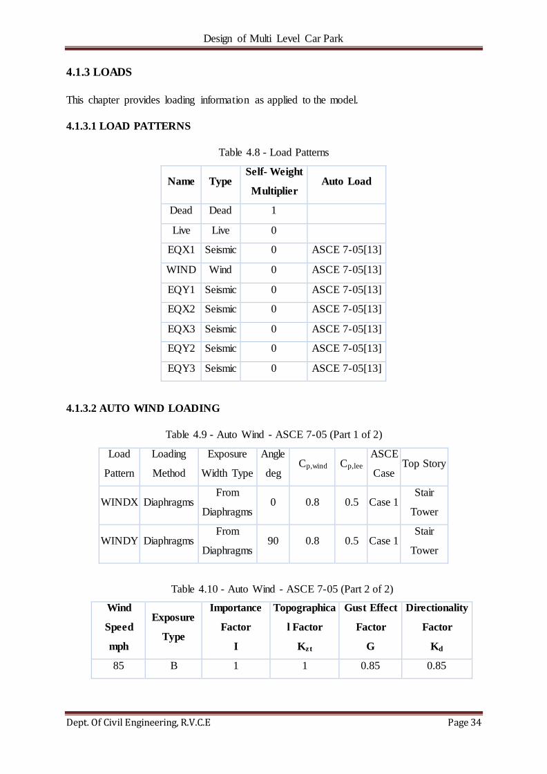
4.1.3 LOADS
This chapter provides loading information as applied to the model.
4.1.3.1 LOAD PATTERNS
Table 4.8 - Load Patterns
Name Type Self- Weight
Multiplier Auto Load
Dead Dead 1
Live Live 0
EQX1 Seismic 0 ASCE 7-05[13]
WIND Wind 0 ASCE 7-05[13]
EQY1 Seismic 0 ASCE 7-05[13]
EQX2 Seismic 0 ASCE 7-05[13]
EQX3 Seismic 0 ASCE 7-05[13]
EQY2 Seismic 0 ASCE 7-05[13]
EQY3 Seismic 0 ASCE 7-05[13]
4.1.3.2 AUTO WIND LOADING
Table 4.9 - Auto Wind - ASCE 7-05 (Part 1 of 2)
Load
Pattern
Loading
Method
Exposure
Width Type
Angle
deg Cp,wind Cp,lee
ASCE
Case Top Story
WINDX Diaphragms From
Diaphragms 0 0.8 0.5 Case 1
Stair
Tower
WINDY Diaphragms From
Diaphragms 90 0.8 0.5 Case 1
Stair
Tower
Table 4.10 - Auto Wind - ASCE 7-05 (Part 2 of 2)
Wind
Speed
mph
Exposure
Type
Importance
Factor
I
Topographica
l Factor
Kzt
Gust Effect
Factor
G
Directionality
Factor
Kd
85 B 1 1 0.85 0.85

Design of Multi Level Car Park
Dept. Of Civil Engineering, R.V.C.E Page 35
4.1.3.3 ASCE 7-05 AUTO WIND LOAD CALCULATION
This calculation presents the automatically generated lateral wind loads for load pattern WIND
according to ASCE 7-05[2], as calculated by ETABS.
Exposure Parameters
Exposure From = Diaphragms
Exposure Category = B
Wind Direction = 0 degrees
Basic Wind Speed, V [ASCE 6.5.4][2]
Windward Coefficient, Cp,wind [ASCE 6.5.11.2.1][2]
Leeward Coefficient, Cp,lee [ASCE 6.5.11.2.1][2]
Wind Cases = All Cases
Top Story = 5A
Bottom Story = Base
Include Parapet = No
Factors and Coefficients
Gradient Height, zg [ASCE Table 6-2][2]
Emperical Exponent, α [ASCE Table 6-2][2]
Topographical Factor, Kzt [ASCE 6.5.7.2] [2]
Directionality Factor, Kd [ASCE 6.5.4.4] [2]
Importance Factor, I [ASCE 6.5.5][2]
Gust Effect Factor, G [ASCE 6.5.8][2]
Lateral Loading
Velocity Pressure, qz [ASCE 6.5.10 Eq. 4-1][2]
Design Wind Pressure, p [ASCE 6.5.12.2.1 Eq. 4-2][2]
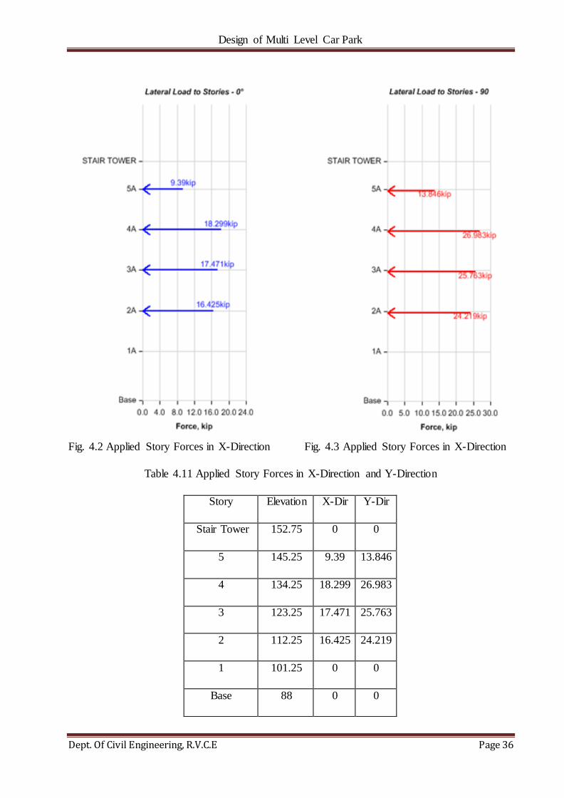
Design of Multi Level Car Park
Dept. Of Civil Engineering, R.V.C.E Page 36
Fig. 4.2 Applied Story Forces in X-Direction Fig. 4.3 Applied Story Forces in X-Direction
Table 4.11 Applied Story Forces in X-Direction and Y-Direction
Story Elevation X-Dir Y-Dir
Stair Tower 152.75 0 0
5 145.25 9.39 13.846
4 134.25 18.299 26.983
3 123.25 17.471 25.763
2 112.25 16.425 24.219
1 101.25 0 0
Base 88 0 0

Design of Multi Level Car Park
Dept. Of Civil Engineering, R.V.C.E Page 37
4.1.3.4 AUTO SEISMIC LOADING
Table 4.12 - Auto Seismic - ASCE 7-05 (Part 1 of 3)
Load
Pattern Type Direction
Eccentricity
%
Ecc.
Overridden
Period
Method
User T
sec Top Story
Bottom
Story R
EQX1 Seismic X No User
Specified 0.416
STAIR
TOWER Base 4
EQY1 Seismic Y No User
Specified 0.416
STAIR
TOWER Base 4
EQX2 Seismic X + Ecc. Y 5 No User
Specified 0.416
STAIR
TOWER Base 4
EQX3 Seismic X - Ecc. Y 5 No User
Specified 0.416
STAIR
TOWER Base 4
EQY2 Seismic Y + Ecc. X 5 No User
Specified 0.416
STAIR
TOWER Base 4
EQY3 Seismic Y - Ecc. X 5 No User
Specified 0.416
STAIR
TOWER Base 4
Table 4.13 - Auto Seismic - ASCE 7-05 (Part 2 of 3)
Ω Cd I SS/S1 Source SS S1 Site
Class Fa Fv SDS SD1
2.5 4 1 User Specified 0.229 0.069 D 1.6 2.4 0.244267 0.1104
2.5 4 1 User Specified 0.229 0.069 D 1.6 2.4 0.244267 0.1104
2.5 4 1 User Specified 0.229 0.069 D 1.6 2.4 0.244267 0.1104
2.5 4 1 User Specified 0.229 0.069 D 1.6 2.4 0.244267 0.1104
2.5 4 1 User Specified 0.229 0.069 D 1.6 2.4 0.244267 0.1104
2.5 4 1 User Specified 0.229 0.069 D 1.6 2.4 0.244267 0.1104

Design of Multi Level Car Park
Dept. Of Civil Engineering, R.V.C.E Page 38
Table 4.14 - Auto Seismic - ASCE 7-05 (Part 3 of 3)
Period
Used
(sec)
Co-eff
Used
Weight
Used
(kip)
Base
Shear
(kip)
0.416 0.061067 11748.71 717.455
0.416 0.061067 11748.71 717.455
0.416 0.061067 11748.71 717.455
0.416 0.061067 11748.71 717.455
0.416 0.061067 11748.71 717.455
0.416 0.061067 11748.71 717.455
4.1.3.5 ASCE 7-05 AUTO SEISMIC LOAD CALCULATION
This calculation presents the automatically generated lateral seismic loads for load pattern EQX1
according to ASCE 7-05[2], as calculated by ETABS.
Direction and Eccentricity
Direction = X
Structural Period
Period Calculation Method = User Specified
User Period
Long-Period Transition Period, TL [ASCE 11.4.5][2]
Factors and Coefficients
Response Modification Factor, R [ASCE Table 12.2-1][2]
System Overstrength Factor, Ω0 [ASCE Table 12.2-1][2]
Deflection Amplification Factor, Cd [ASCE Table 12.2-1][2]
Importance Factor, I [ASCE Table 11.5-1][2]
Ss and S1 Source= User Specified

Design of Multi Level Car Park
Dept. Of Civil Engineering, R.V.C.E Page 39
Mapped MCE Spectral Response Acceleration, Ss [ASCE 11.4.1][2]
Mapped MCE Spectral Response Acceleration, S1 [ASCE 11.4.1][2]
Site Class [ASCE Table 20.3-1][2] = D - Stiff Soil
Site Coefficient, Fa [ASCE Table 4.3-1][2]
Site Coefficient, Fv [ASCE Table 4.3-2][2]
Seismic Response
MCE Spectral Response Acceleration, SMS
[ASCE 11.4.3, Eq. 4.4-1][2]
MCE Spectral Response Acceleration, SM1
[ASCE 11.4.3, Eq. 4.4-2][2]
Design Spectral Response Acceleration, SDS
[ASCE 11.4.4, Eq. 4.4-3][2]
Design Spectral Response Acceleration, SD1
[ASCE 11.4.4, Eq. 4.4-4][2]
Equivalent Lateral Forces
Seismic Response Coefficient, CS [ASCE 12.8.1.1, Eq. 4.5-2]
[ASCE 12.8.1.1, Eq. 4.5-3][2]
[ASCE 12.8.1.1, Eq. 4.5-5][2]
Calculated Base Shear
Table 4.15 Calculated Base Shear along direction-X
Direction Period Used
(sec) Cs
W
(kip)
V
(kip)
X 0.416 0.061067 11748.7099 717.4545

Design of Multi Level Car Park
Dept. Of Civil Engineering, R.V.C.E Page 40
Applied Story Forces
Fig.4.4 Lateral Load in X- Direction.
Table 4.16 Lateral Load in X- Direction.
Story Elevation X-Dir Y-Dir
Stair Tower 152.75 0 0
5 145.25 9.39 0
4 134.25 18.299 0
3 123.25 17.471 0
2 112.25 16.425 0
1 101.25 0 0
Base 88 0 0

Design of Multi Level Car Park
Dept. Of Civil Engineering, R.V.C.E Page 41
4.1.3.6 ASCE 7-05 AUTO SEISMIC LOAD CALCULATION
This calculation presents the automatically generated lateral seismic loads for load pattern EQY1
according to ASCE 7-05, as calculated by ETABS.
Direction and Eccentricity
Direction = Y
Structural Period
Period Calculation Method = User Specified
User Period
Long-Period Transition Period, TL [ASCE 11.4.5][2]
Factors and Coefficients
Response Modification Factor, R [ASCE Table 12.2-1][2]
System Overstrength Factor, Ω0 [ASCE Table 12.2-1][2]
Deflection Amplification Factor, Cd [ASCE Table 12.2-1][2]
Importance Factor, I [ASCE Table 11.5-1][2]
Ss and S1 Source= User Specified
Mapped MCE Spectral Response Acceleration, Ss [ASCE 11.4.1][2]
Mapped MCE Spectral Response Acceleration, S1 [ASCE 11.4.1][2]
Site Class [ASCE Table 20.3-1][2] = D - Stiff Soil
Site Coefficient, Fa [ASCE Table 11.4-1][2]
Site Coefficient, Fv [ASCE Table 11.4-2][2]
Seismic Response
MCE Spectral Response Acceleration, SMS
[ASCE 11.4.3, Eq. 4.2-1][2]

Design of Multi Level Car Park
Dept. Of Civil Engineering, R.V.C.E Page 42
MCE Spectral Response Acceleration, SM1
[ASCE 11.4.3, Eq. 4.2-2][2]
Design Spectral Response Acceleration,
SDS[ASCE 11.4.4, Eq. 4.2-3][2]
... (4.1)
Design Spectral Response Acceleration, SD1
[ASCE 11.4.4, Eq. 4.2-4][2]
. ... (4.2)
Equivalent Lateral Forces
Seismic Response Coefficient, CS [ASCE 12.8.1.1, Eq. 4.3-2][2]
... (4.3)
[ASCE 12.8.1.1, Eq. 4.3-3][2]
... (4.4)
[ASCE 12.8.1.1, Eq. 4.3-4][2]
Calculated Base Shear
Table 4.17 Calculated Base Shear along direction-Y
Direction Period Used
(sec) Cs
W
(kip)
V
(kip)
Y 0.416 0.06106
7
11748.709
9
717.454
5

Design of Multi Level Car Park
Dept. Of Civil Engineering, R.V.C.E Page 43
Applied Story Forces
Fig. 4.5 Lateral Loads along direction-Y
Table 4.18 Lateral Loads along direction-Y
Story Elevation X-Dir Y-Dir
Ft. kip kip
STAIR
TOWER 152.75 0 25.831
5 145.25 0 230.664
4 134.25 0 197.691
3 123.25 0 148.504
2 112.25 0 103.992
1 101.25 0 10.772
Base 88 0 0

Design of Multi Level Car Park
Dept. Of Civil Engineering, R.V.C.E Page 44
4.1.3.7 ASCE 7-05 AUTO SEISMIC LOAD CALCULATION
This calculation presents the automatically generated lateral seismic loads for load pattern EQX2
according to ASCE 7-05, as calculated by ETABS.
Direction and Eccentricity
Direction = X + Eccentricity Y
Eccentricity Ratio = 5% for all diaphragms
Structural Period
Period Calculation Method = User Specified
User Period
Long-Period Transition Period, TL [ASCE 11.4.5][2]
Factors and Coefficients
Response Modification Factor, R [ASCE Table 12.2-1][2]
System Overstrength Factor, Ω0 [ASCE Table 12.2-1][2]
Deflection Amplification Factor, Cd [ASCE Table 12.2-1][2]
Importance Factor, I [ASCE Table 11.5-1][2]
Ss and S1Source=User Specified
Mapped MCE Spectral Response Acceleration, Ss [ASCE
11.4.1][2]
Mapped MCE Spectral Response Acceleration, S1 [ASCE
11.4.1][2]
Site Class [ASCE Table 20.3-1][2] = D - Stiff Soil
Site Coefficient, Fa [ASCE Table 11.4-1][2]
Site Coefficient, Fv [ASCE Table 11.4-2][2]

Design of Multi Level Car Park
Dept. Of Civil Engineering, R.V.C.E Page 45
Seismic Response
MCE Spectral Response Acceleration, SMS
[ASCE 11.4.3, Eq. 4.2-1][2]
... (4.5)
MCE Spectral Response Acceleration,
SM1[ASCE 11.4.3, Eq. 4.2-2][2]
... (4.6)
Design Spectral Response Acceleration, SDS
[ASCE 11.4.4, Eq. 4.2-3][2]
... (4.7)
Design Spectral Response Acceleration, SD1
[ASCE 11.4.4, Eq. 4.2-4] [2]
... (4.8)
Equivalent Lateral Forces
Seismic Response Coefficient, CS
[ASCE 12.8.1.1, Eq. 4.3-2]
... (4.9)
[ASCE 12.8.1.1, Eq. 4.3-3] [2]
... (4.10)
[ASCE 12.8.1.1, Eq. 4.3-5] [2]
Calculated Base Shear
Table 4.19 Calculated Base Shear along direction X+Ecc Y
Direction Period Used
(sec) Cs
W
(kip)
V
(kip)
X + Ecc. Y 0.416 0.061067 11748.7099 717.4545
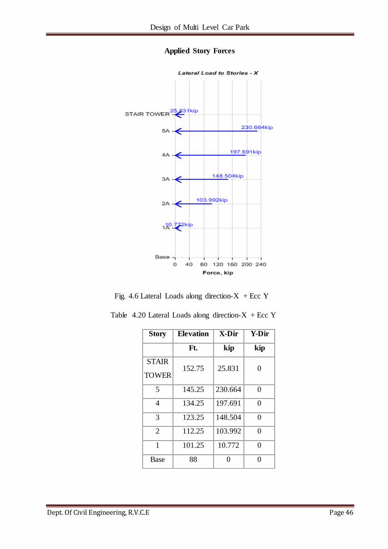
Design of Multi Level Car Park
Dept. Of Civil Engineering, R.V.C.E Page 46
Applied Story Forces
Fig. 4.6 Lateral Loads along direction-X + Ecc Y
Table 4.20 Lateral Loads along direction-X + Ecc Y
Story Elevation X-Dir Y-Dir
Ft. kip kip
STAIR
TOWER 152.75 25.831 0
5 145.25 230.664 0
4 134.25 197.691 0
3 123.25 148.504 0
2 112.25 103.992 0
1 101.25 10.772 0
Base 88 0 0

Design of Multi Level Car Park
Dept. Of Civil Engineering, R.V.C.E Page 47
4.1.3.8 ASCE 7-05 AUTO SEISMIC LOAD CALCULATION
This calculation presents the automatically generated lateral seismic loads for load pattern EQX3
according to ASCE 7-05, as calculated by ETABS.
Direction and Eccentricity
Direction = X - Eccentricity Y
Eccentricity Ratio = 5% for all diaphragms
Structural Period
Period Calculation Method = User Specified
User Period
Long-Period Transition Period, TL [ASCE 11.4.5] [2]
Factors and Coefficients
Response Modification Factor, R [ASCE Table 12.2-1] [2]
System Overstrength Factor, Ω0 [ASCE Table 12.2-1] [2]
Deflection Amplification Factor, Cd [ASCE Table 12.2-1] [2]
Importance Factor, I [ASCE Table 11.5-1] [2]
Ss and S1 Source=User Specified
Mapped MCE Spectral Response Acceleration, Ss [ASCE 11.4.1]
Mapped MCE Spectral Response Acceleration, S1 [ASCE 11.4.1]
Site Class [ASCE Table 20.3-1] [2]= D - Stiff Soil
Site Coefficient, Fa [ASCE Table 11.4-1] [2]
Site Coefficient, Fv [ASCE Table 11.4-2] [2]

Design of Multi Level Car Park
Dept. Of Civil Engineering, R.V.C.E Page 48
Seismic Response
MCE Spectral Response Acceleration, SMS
[ASCE 11.4.3, Eq. 4.2-1] [2]
... (4.11)
MCE Spectral Response Acceleration, SM1
[ASCE 11.4.3, Eq. 4.2-2] [2]
... (4.12)
Design Spectral Response Acceleration, SDS
[ASCE 11.4.4, Eq. 4.2-3] [2]
... (4.13)
Design Spectral Response Acceleration, SD1
[ASCE 11.4.4, Eq. 4.2-4] [2]
... (4.14)
Equivalent Lateral Forces
Seismic Response Coefficient, CS [ASCE 12.8.1.1, Eq. 4.3-2]
... (4.15)
[ASCE 12.8.1.1, Eq. 4.3-3] [2]
... (4.16)
[ASCE 12.8.1.1, Eq. 4.3-5] [2]
Calculated Base Shear
Table 4.21 Calculated Base Shear along direction X - Ecc Y
Direction Period Used
(sec) Cs
W
(kip)
V
(kip)
X - Ecc. Y 0.416 0.061067 11748.7099 717.4545

Design of Multi Level Car Park
Dept. Of Civil Engineering, R.V.C.E Page 49
Applied Story Forces
Fig. 4.7 Lateral Loads along direction-X - Ecc Y
Table 4.22 Lateral Loads along direction-X –Ecc Y
Story Elevation X-Dir Y-Dir
Ft. kip kip
STAIR
TOWER 152.75 25.831 0
5 145.25 230.664 0
4 134.25 197.691 0
3 123.25 148.504 0
2 112.25 103.992 0
1 101.25 10.772 0
Base 88 0 0
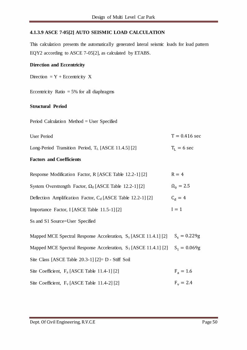
Design of Multi Level Car Park
Dept. Of Civil Engineering, R.V.C.E Page 50
4.1.3.9 ASCE 7-05[2] AUTO SEISMIC LOAD CALCULATION
This calculation presents the automatically generated lateral seismic loads for load pattern
EQY2 according to ASCE 7-05[2], as calculated by ETABS.
Direction and Eccentricity
Direction = Y + Eccentricity X
Eccentricity Ratio = 5% for all diaphragms
Structural Period
Period Calculation Method = User Specified
User Period
Long-Period Transition Period, TL [ASCE 11.4.5] [2]
Factors and Coefficients
Response Modification Factor, R [ASCE Table 12.2-1] [2]
System Overstrength Factor, Ω0 [ASCE Table 12.2-1] [2]
Deflection Amplification Factor, Cd [ASCE Table 12.2-1] [2]
Importance Factor, I [ASCE Table 11.5-1] [2]
Ss and S1 Source=User Specified
Mapped MCE Spectral Response Acceleration, Ss [ASCE 11.4.1] [2]
Mapped MCE Spectral Response Acceleration, S1 [ASCE 11.4.1] [2]
Site Class [ASCE Table 20.3-1] [2]= D - Stiff Soil
Site Coefficient, Fa [ASCE Table 11.4-1] [2]
Site Coefficient, Fv [ASCE Table 11.4-2] [2]

Design of Multi Level Car Park
Dept. Of Civil Engineering, R.V.C.E Page 51
Seismic Response
MCE Spectral Response Acceleration, SMS
[ASCE 11.4.3, Eq. 4.2-1] [2]
... (4.17)
MCE Spectral Response Acceleration, SM1
[ASCE 11.4.3, Eq. 4.2-2] [2]
... (4.18)
Design Spectral Response Acceleration,
SDS [ASCE 11.4.4, Eq. 4.2-3] [2]
... (4.19)
Design Spectral Response Acceleration,
SD1 [ASCE 11.4.4, Eq. 4.2-4] [2]
... (4.20)
Equivalent Lateral Forces
Seismic Response Coefficient, CS [ASCE 12.8.1.1, Eq. 4.3-2] [2]
... (4.21)
[ASCE 12.8.1.1, Eq. 4.3-3] [2]
... (4.22)
[ASCE 12.8.1.1, Eq. 4.3-5] [2]
Calculated Base Shear
Table 4.23 Calculated Base Shear along direction Y + Ecc X
Direction Period Used
(sec) Cs
W
(kip)
V
(kip)
Y + Ecc. X 0.416 0.061067 11748.7099 717.4545
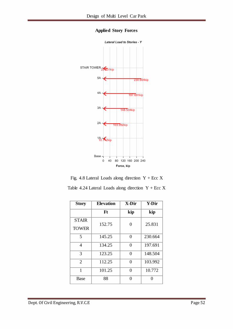
Design of Multi Level Car Park
Dept. Of Civil Engineering, R.V.C.E Page 52
Applied Story Forces
Fig. 4.8 Lateral Loads along direction Y + Ecc X
Table 4.24 Lateral Loads along direction Y + Ecc X
Story Elevation X-Dir Y-Dir
Ft kip kip
STAIR
TOWER 152.75 0 25.831
5 145.25 0 230.664
4 134.25 0 197.691
3 123.25 0 148.504
2 112.25 0 103.992
1 101.25 0 10.772
Base 88 0 0

Design of Multi Level Car Park
Dept. Of Civil Engineering, R.V.C.E Page 53
4.1.3.10 ASCE 7-05[2] Auto Seismic Load Calculation
This calculation presents the automatically generated lateral seismic loads for load pattern
EQY3 according to ASCE 7-05[2], as calculated by ETABS.
Direction and Eccentricity
Direction = Y - Eccentricity X
Eccentricity Ratio = 5% for all diaphragms
Structural Period
Period Calculation Method = User Specified
User Period
Long-Period Transition Period, TL [ASCE 11.4.5] [2]
Factors and Coefficients
Response Modification Factor, R [ASCE Table 12.2-1] [2]
System Overstrength Factor, Ω0 [ASCE Table 12.2-1] [2]
Deflection Amplification Factor, Cd [ASCE Table 12.2-1] [2]
Importance Factor, I [ASCE Table 11.5-1] [2]
Ss and S1 Source=User Specified
Mapped MCE Spectral Response Acceleration, Ss [ASCE 11.4.1] [2]
Mapped MCE Spectral Response Acceleration, S1 [ASCE 11.4.1] [2]
Site Class [ASCE Table 20.3-1] [2] = D - Stiff Soil
Site Coefficient, Fa [ASCE Table 11.4-1] [2]
Site Coefficient, Fv [ASCE Table 11.4-2] [2]

Design of Multi Level Car Park
Dept. Of Civil Engineering, R.V.C.E Page 54
Seismic Response
MCE Spectral Response Acceleration, SMS
[ASCE 11.4.3, Eq. 4.2-1] [2]
... (4.23)
MCE Spectral Response Acceleration,
SM1[ASCE 11.4.3, Eq. 4.2-2] [2]
... (4.24)
Design Spectral Response Acceleration, SDS
[ASCE 11.4.4, Eq. 4.2-3] [2]
... (4.25)
Design Spectral Response Acceleration, SD1
[ASCE 11.4.4, Eq. 4.2-4] [2]
... (4.26)
Equivalent Lateral Forces
Seismic Response Coefficient, CS
[ASCE 12.8.1.1, Eq. 4.3-2]
... (4.27)
[ASCE 12.8.1.1, Eq. 4.3-3] [2]
... (4.28)
[ASCE 12.8.1.1, Eq. 4.3-5] [2]
Calculated Base Shear
Table 4.25 Calculated Base Shear along direction Y - Ecc X
Direction Period Used
(sec) Cs
W
(kip)
V
(kip)
Y - Ecc. X 0.416 0.061067 11748.7099 717.4545

Design of Multi Level Car Park
Dept. Of Civil Engineering, R.V.C.E Page 55
Applied Story Forces
Fig. 4.9 Lateral Loads along direction Y - Ecc X
Table 4.26 Lateral Loads along direction Y- Ecc X
Story Elevation X-Dir Y-Dir
ft kip kip
STAIR
TOWER 152.75 0 25.831
5 145.25 0 230.664
4 134.25 0 197.691
3 123.25 0 148.504
2 112.25 0 103.992
1 101.25 0 10.772
Base 88 0 0
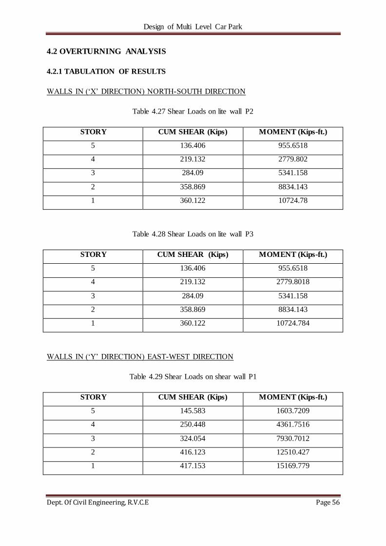
Design of Multi Level Car Park
Dept. Of Civil Engineering, R.V.C.E Page 56
4.2 OVERTURNING ANALYSIS
4.2.1 TABULATION OF RESULTS
WALLS IN (‗X‘ DIRECTION) NORTH-SOUTH DIRECTION
Table 4.27 Shear Loads on lite wall P2
STORY CUM SHEAR (Kips) MOMENT (Kips-ft.)
5 136.406 955.6518
4 219.132 2779.802
3 284.09 5341.158
2 358.869 8834.143
1 360.122 10724.78
Table 4.28 Shear Loads on lite wall P3
STORY CUM SHEAR (Kips) MOMENT (Kips-ft.)
5 136.406 955.6518
4 219.132 2779.8018
3 284.09 5341.158
2 358.869 8834.143
1 360.122 10724.784
WALLS IN (‗Y‘ DIRECTION) EAST-WEST DIRECTION
Table 4.29 Shear Loads on shear wall P1
STORY CUM SHEAR (Kips) MOMENT (Kips-ft.)
5 145.583 1603.7209
4 250.448 4361.7516
3 324.054 7930.7012
2 416.123 12510.427
1 417.153 15169.779
Design of Multi Level Car Park
Dept. Of Civil Engineering, R.V.C.E Page 57
Table 4.30 Shear Loads on shear wall P4
STORY CUM SHEAR (Kips) MOMENT (Kips-ft.)
5 130.678 1436.72
4 195.235 3583.605
3 252.924 6365.844
2 308.047 9753.719
1 309.077 11724.09
Table 4.31 Lite Wall Lateral Foundation Forces
STORY PIER LOAD LOCATION V2(Kips) M3(Kips-ft.)
1 P3 WIND X Bottom 30.973 798.3737
1 P3 EQX1 Bottom 360.182 10724.55
1 P3 EQX2 Bottom 360.242 10724.33
1 P3 EQX3 Bottom 360.122 10724.78
1 P2 WIND X Bottom 30.973 798.3737
1 P2 EQX1 Bottom 360.182 10724.55
1 P2 EQX2 Bottom 360.242 10724.33
1 P2 EQX3 Bottom 360.122 10724.78
Table 4.32 Shear Wall Lateral Foundation Forces
STORY PIER LOAD LOCATION V2(Kips) M3(Kips-ft.)
1 P1 WIND Y Bottom 45.983 1449.4999
1 P1 EQX1 Bottom 348.148 12794.7234
1 P1 EQX2 Bottom 279.143 10419.6677
1 P1 EQX3 Bottom 417.153 15169.7791
1 P4 WINDY Bottom 45.966 1453.5021
1 P4 EQX1 Bottom 378.029 14106.5006
1 P4 EQX2 Bottom 446.981 16488.9157
1 P4 EQX3 Bottom 309.077 11724.0856

Design of Multi Level Car Park
Dept. Of Civil Engineering, R.V.C.E Page 58
4.2.2 OVERTURNING ANALYSIS FOR WALLS IN X-DIRECTION
Assumptions
PDL is the sum of the wall panel self-weight and the DT stem loads (Linear load
multiplied by panel width) from the Foundation Load Summary Sheet.
PDL conservatively acts at the centre of the Wall Panel.
The Tension support is 1.50' from the end.
The compression support is 0.50' from the end.
For all Light Walls, the Lever arm distance to calculate the Tu will be Width of LW' -
(1.50 + 0.5').
Fig. 4.10 Elevation of LITEWALLS
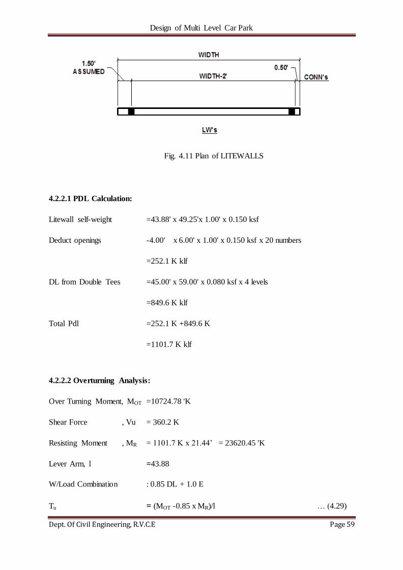
Design of Multi Level Car Park
Dept. Of Civil Engineering, R.V.C.E Page 59
Fig. 4.11 Plan of LITEWALLS
4.2.2.1 PDL Calculation:
Litewall self-weight =43.88' x 49.25'x 1.00' x 0.150 ksf
Deduct openings -4.00' x 6.00' x 1.00' x 0.150 ksf x 20 numbers
=252.1 K klf
DL from Double Tees =45.00' x 59.00' x 0.080 ksf x 4 levels
=849.6 K klf
Total Pdl =252.1 K +849.6 K
=1101.7 K klf
4.2.2.2 Overturning Analysis:
Over Turning Moment, MOT =10724.78 'K
Shear Force , Vu = 360.2 K
Resisting Moment , MR = 1101.7 K x 21.44‘ = 23620.45 'K
Lever Arm, l =43.88
W/Load Combination : 0.85 DL + 1.0 E
Tu = (MOT -0.85 x MR)/l … (4.29)
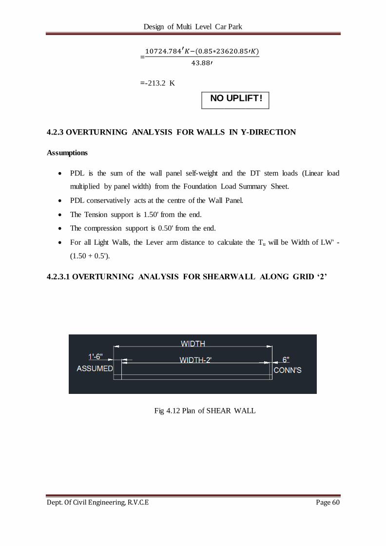
Design of Multi Level Car Park
Dept. Of Civil Engineering, R.V.C.E Page 60
=
=-213.2 K
4.2.3 OVERTURNING ANALYSIS FOR WALLS IN Y-DIRECTION
Assumptions
PDL is the sum of the wall panel self-weight and the DT stem loads (Linear load
multiplied by panel width) from the Foundation Load Summary Sheet.
PDL conservatively acts at the centre of the Wall Panel.
The Tension support is 1.50' from the end.
The compression support is 0.50' from the end.
For all Light Walls, the Lever arm distance to calculate the Tu will be Width of LW' -
(1.50 + 0.5').
4.2.3.1 OVERTURNING ANALYSIS FOR SHEARWALL ALONG GRID ‘2’
Fig 4.12 Plan of SHEAR WALL
NO UPLIFT!

Design of Multi Level Car Park
Dept. Of Civil Engineering, R.V.C.E Page 61
Fig 4.13 Elevation of SHEAR WALL
4.2.3.1.1 PDL Calculation:
Shear wall self-weight = 30.00‘ x 50.38' x 1.00' x 0.150 ksf
Pilaster self-weight =3.00' x 50.38' x 1.00' x 0.150 ksf
=249.4 K klf
Deduct openings -4.00' x 5.00' x 1.00' x 0.150 ksfx8 numbers

Design of Multi Level Car Park
Dept. Of Civil Engineering, R.V.C.E Page 62
=225.4 K klf
DL from IT-beams =1.09 klf x 22.94' x4 levels
=100.0 K klf
DL from Double Tees =21.00' x 59.00' x 0.081 ksf x 4 levels
=401.4 K klf
Load from Concrete pad = ((32.0' x 16.0' x 0.075 ksf) x 16.0') / 61.5'
=10.0 K klf
Total Pdl =225.4 K +100.0 K +401.4 K +10.0 K
=736.8 K klf
4.2.3.1.2 Over Turning Analysis:
Over Turning Moment, MOT=15169.78 'K
Shear Force , Vu =417 K
Resisting Moment , MR =760.8 K x 14.50‘ = 11031.60 'K
Lever Arm, l = 28‘
W/Load Combination : 0.85 DL + 1.0 E
Tension, Tu = (MOT -0.85 x MR)/l … (4.30)
=
= 206.9 ‘K
4.2.3.1.3 Calculation of Reinforcement
Steel Required, As =Tu/Φfy … (4.31)
=206.9/ (0.9*60)
PROVIDE As
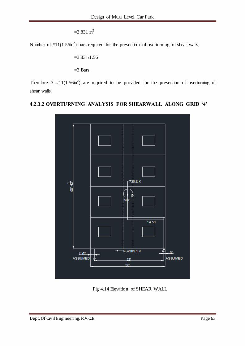
Design of Multi Level Car Park
Dept. Of Civil Engineering, R.V.C.E Page 63
=3.831 in2
Number of #11(1.56in2) bars required for the prevention of overturning of shear walls,
=3.831/1.56
=3 Bars
Therefore 3 #11(1.56in2) are required to be provided for the prevention of overturning of
shear walls.
4.2.3.2 OVERTURNING ANALYSIS FOR SHEARWALL ALONG GRID ‘4’
Fig 4.14 Elevation of SHEAR WALL

Design of Multi Level Car Park
Dept. Of Civil Engineering, R.V.C.E Page 64
Fig 4.15 Plan of SHEAR WALL
4.2.3.2.1 PDL Calculation:
Shear wall self-weight = 30.00‘ x 50.38' x 1.00' x 0.150 ksf
Pilaster self-weight =3.00' x 50.38' x 1.00' x 0.150 ksf
=249.4 K klf
Deduct openings -4.00' x 5.00' x 1.00' x 0.150 ksf x8 numbers
=225.4 K klf
DL from IT-beams =1.09 klf x 22.94' x4 levels
=100.0 K klf
DL from Double Tees =21.00' x 59.00' x 0.081 ksf x 4 levels
=401.4 K klf
Load from Concrete pad = ((32.0' x 16.0' x 0.075 ksf) x 16.0') / 61.5'
=10.0 K klf
Total Pdl =225.4 K +100.0 K +401.4 K +10.0 K
=736.8 K klf
4.2.3.2.2 Over Turning Analysis:
Over Turning Moment, MOT=15169.78 'K
Shear Force , Vu =417 K
Resisting Moment , MR =760.8 K x 14.50‘
= 11031.60 'K
Lever Arm, l =28‘
Design of Multi Level Car Park
Dept. Of Civil Engineering, R.V.C.E Page 65
W/Load Combination : 0.85 DL + 1.0 E
Tu = (MOT -0.85 x MR)/l … (4.32)
=
= 254 ‘K
4.2.3.2.3 Calculation of Steel Required For the Prevention of Overturning of Shear
Walls
Steel Required, As =Tu/Φfy … (4.33)
=254/ (0.9*60)
=4.704 in2
Number of #11(1.56in2) bars required for the prevention of overturning of shear walls,
=4.704/1.56
=4 Bars
Therefore 4 #11(1.56in2) are required to be provided for the prevention of overturning of
shear walls.
4.3 DIAPHRAGM ANALYSIS
Diaphragms transmit inertial forces from the floor system to the vertical elements of the
seismic force-resisting system. They also tie the vertical elements together and thereby
stabilize and transmit forces among these elements as may be required during earthquake
shaking. Diaphragms are thus an essential part of the seismic force-resisting system and
require design attention by the structural engineer to ensure the structural system performs
adequately during earthquake shaking.[11]
PROVIDE As
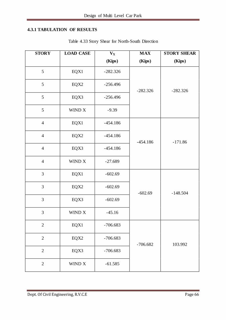
Design of Multi Level Car Park
Dept. Of Civil Engineering, R.V.C.E Page 66
4.3.1 TABULATION OF RESULTS
Table 4.33 Story Shear for North-South Direction
STORY LOAD CASE VX
(Kips)
MAX
(Kips)
STORY SHEAR
(Kips)
5 EQX1 -282.326
-282.326 -282.326
5 EQX2 -256.496
5 EQX3 -256.496
5 WIND X -9.39
4 EQX1 -454.186
-454.186 -171.86
4 EQX2 -454.186
4 EQX3 -454.186
4 WIND X -27.689
3 EQX1 -602.69
-602.69 -148.504
3 EQX2 -602.69
3 EQX3 -602.69
3 WIND X -45.16
2 EQX1 -706.683
-706.682 103.992
2 EQX2 -706.683
2 EQX3 -706.683
2 WIND X -61.585
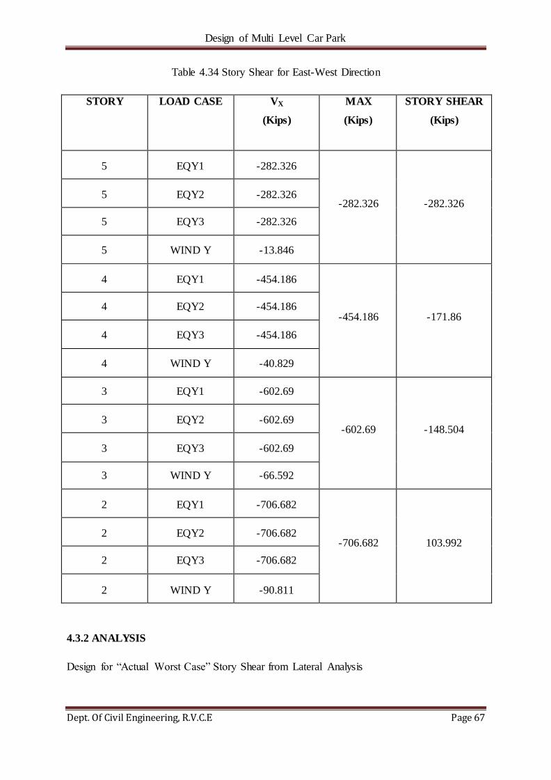
Design of Multi Level Car Park
Dept. Of Civil Engineering, R.V.C.E Page 67
Table 4.34 Story Shear for East-West Direction
STORY LOAD CASE VX
(Kips)
MAX
(Kips)
STORY SHEAR
(Kips)
5 EQY1 -282.326
-282.326 -282.326 5 EQY2 -282.326
5 EQY3 -282.326
5 WIND Y -13.846
4 EQY1 -454.186
-454.186 -171.86 4 EQY2 -454.186
4 EQY3 -454.186
4 WIND Y -40.829
3 EQY1 -602.69
-602.69 -148.504 3 EQY2 -602.69
3 EQY3 -602.69
3 WIND Y -66.592
2 EQY1 -706.682
-706.682 103.992 2 EQY2 -706.682
2 EQY3 -706.682
2 WIND Y -90.811
4.3.2 ANALYSIS
Design for ―Actual Worst Case‖ Story Shear from Lateral Analysis

Design of Multi Level Car Park
Dept. Of Civil Engineering, R.V.C.E Page 68
However, we will check this value against Fp as calculated from IBC 2006 (ASCE 7-05, EQ.
12.10)
∑
∑
Actual Calculated Fp Value (Design Story Shear) … (4.34)
Fp=0.2IESDSwp Minimum Calculated Fp Value … (4.35)
Fp=0.4IESDSwp Maximum Calculated Fp Value … (4.36)
IE=1.00 SDS=0.244
Table 4.35 Comparison between Lateral Analysis Story Shear and IBC Story Shear for N-S
Direction
Story
Shear
(Kips)
Story
Shear
(Kips)
Cumulative
Weight
(Kips)
Wt At
Each
Level
(Kips)
Fp
(Min)
(Kips)
Fp
(Max)
(Kips)
Design
Story
Shear
(Kips)
5 282.326 282.326 3030.97 3060.97 147.911 295.822 282.326
4 454.186 171.86 5848.32 2787.35 136.024 272.048 216.47
3 602.69 148.504 8635.67 2787.35 136.024 272.048 194.4
2 706.682 103.992 11423.03 2787.35 136.024 272.048 172.44
Table 4.36 Comparison between Lateral Analysis Story Shear and IBC Story Shear for E-W
Direction
Story
Shear
(Kips)
Story
Shear
(Kips)
Cumulative
Weight
(Kips)
Wt At
Each
Level
(Kips)
Fp
(Min)
(Kips)
Fp
(Max)
(Kips)
Design
Story
Shear
(Kips)
5 282.326 282.326 3030.97 3060.97 147.911 295.822 282.326
4 454.186 171.86 5848.32 2787.35 136.024 272.048 216.47
3 602.69 148.504 8635.67 2787.35 136.024 272.048 194.4
2 706.682 103.992 11423.03 2787.35 136.024 272.048 172.44

Design of Multi Level Car Park
Dept. Of Civil Engineering, R.V.C.E Page 69
4.3.2.1 DIAPHRAGM ANALYSIS IN THE N-S DIRECTION
Entire Floor is assumed as one Single Diaphragm for the analysis in North-South Direction.
Fig. 4.16 Plan of Diaphragm under consideration in N-S direction
Critical Case Shear is at Level 5
Worst case shear loads occur at Level 5 =282.326 kips
Total load at worst case story Eu (kips/ft.) =282.326 kips/118.00‘
=2.393 kips/ft.
Seismic Force "E" is resisted by the Lite walls along Grid "B"
N SEISMIC
FORCE (E)

Design of Multi Level Car Park
Dept. Of Civil Engineering, R.V.C.E Page 70
Fig. 4.17 Bending Moment and Shear Force Diagrams for Diaphragm in N-S direction
Worst Case Mu = (2.393 klf x 59 ^ 2) /2 =4165.02 kip-ft.
d = (177.58' - 7') =170.58'
Design Tu =4165.02 kips / 170.58 ft. =24.42 kips
Tu to be resisted by DT to ITB connection
4.3.2.2 DIAPHRAGM ANALYSIS IN THE E-W DIRECTION
Entire Floor is divided into (4) Separate Diaphragms -
2 Flat Diaphragms-Diaphragm #1 b/w Grids 'A-C'/'1-2'
Diaphragm #2 b/w Grids 'A-C'/'4-5'
2 Ramp Diaphragms-Diaphragm #3 b/w Grids 'A-B'/'2-4'
Diaphragm #4 b/w Grids 'B-C'/'2-4'
1.82 klf
C
59.0'
A
59.0'
B
107.4 kips
3167.7 kips-ft
118.0'
107.4 kips
Vu
Mu
2.393 kips/ft.
141.19 kips
141.19 kips
4165.02 kips/ft.

Design of Multi Level Car Park
Dept. Of Civil Engineering, R.V.C.E Page 71
4.3.2.2.1 DIAPHRAGM ANALYSIS (#1 & #2)
Fig. 4.18 Plan of Diaphragm (#1 & #2)
Critical Case Shear is at Level 5
Shear load is at Level 5 =282.326 kips
Total load at worst case story Eu (kips/ft.) =282.326 K/174.0‘=1.623 k/ft.
Seismic Force "E" is resisted by the Shear Walls along Grids "2" & "4".
N
SEISMIC
FORCE (E)
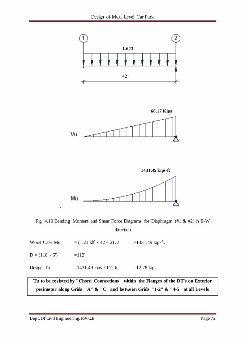
Design of Multi Level Car Park
Dept. Of Civil Engineering, R.V.C.E Page 72
`
Fig. 4.19 Bending Moment and Shear Force Diagrams for Diaphragm (#1 & #2) in E-W
direction
Worst Case Mu = (1.23 klf x 42 ^ 2) /2 =1431.49 kip-ft.
D = (118' - 6') =112'
Design Tu =1431.49 kips / 112 ft. =12.78 kips
Tu to be resisted by "Chord Connections" within the Flanges of the DT's on Exterior
perimeter along Grids "A" & "C" and between Grids "1-2" & "4-5" at all Levels
1.623
42‘
68.17 Kips
1431.49 kips-ft
Kips

Design of Multi Level Car Park
Dept. Of Civil Engineering, R.V.C.E Page 73
4.3.2.2.2 DIAPHRAGM ANALYSIS (#3 & #4)
Fig. 4.20 Plan of Diaphragm (#3 & #4)
Critical Case Shear is at Level 5
Shear load is at Level 5 =282.326 kips
Total load at worst case story Eu (kips/ft.) =282.326 K/(174.0‘ * 2)=0.811 k/ft.
Seismic Force "E" is resisted by the Shear Walls along Grids "2" & "4".
N
SEISMIC
FORCE (E)

Design of Multi Level Car Park
Dept. Of Civil Engineering, R.V.C.E Page 74
Fig. 4.21 Bending Moment and Shear Force Diagrams for Diaphragm (#3 & #4) in E-W
direction
Worst Case Mu = (0.811 klf x 90 ^ 2) / 8 =821.14 kip-ft.
d = (59' - 6') =53'
Design Tu =821.14 kips / 53 ft. =15.49 kips
Tu to be resisted by "Chord Connections" within the Flanges of the DT's on Exterior
perimeter along Grids "A", "B" & "C" and between Grids "2"-"4" at all Levels.
***
0.811 kips/ft.
90.00’
36.5 kips
36.5 kips
821.14 kips-ft.

Design of Multi Level Car Park
Dept. Of Civil Engineering, R.V.C.E Page 75
CHAPTER 5
DESIGN OF CONNECTIONS
The design of connections is one of the most important considerations in the structural design
of a precast concrete structure. There are many successful solutions to each connection
condition. The purpose of a connection is to transfer load, restrain movement, and/or provide
stability. Within any one connection, there may be several load transfers; each one must be
designed for adequate strength and ductility and be appropriately detailed. The detailing
should take into account allowable tolerances, provide for a good fit between the selected
materials.
5.1 DESIGN OF FOUNDATION CONNECTIONS
Foundation connections are used in the part of the building where connections between pre-
cast products and CIP are required to be established. It helps in maintaining structural
integrity and hence improves the redundancy and ductility of structures, thereby reducing the
risk of failure or collapse of parts or all of a building due to damage occurring to a relatively
small area of a building.
5.1.1 DESIGN OF COLUMN FOUNDATION CONNECTIONS FOR COLUMN24'' x
34''
CONNECTION LOADS
TENSION LOADS
Since the Column is pocketed for Spandrels, Effective Gross Area Ag is considered only as
24'' x 21''
Tu,reqd =200 Ag =200 (24'' x 21'') =100.8 K … (5.1)
BEARING-AXIAL LOADS
Service DL to Column =760.1 K
Service LL to Column =185.7 K Pu = 1228.9 K
Service SL to Column =39.3 K

Design of Multi Level Car Park
Dept. Of Civil Engineering, R.V.C.E Page 76
Fig. 5.1 Plan and Section of Column-Foundation Connection
Factored Load to Column =1.2 x 760.086 K + 1.6 x 185.698 K + 0.5 x 39.344 K
=1228.9 K
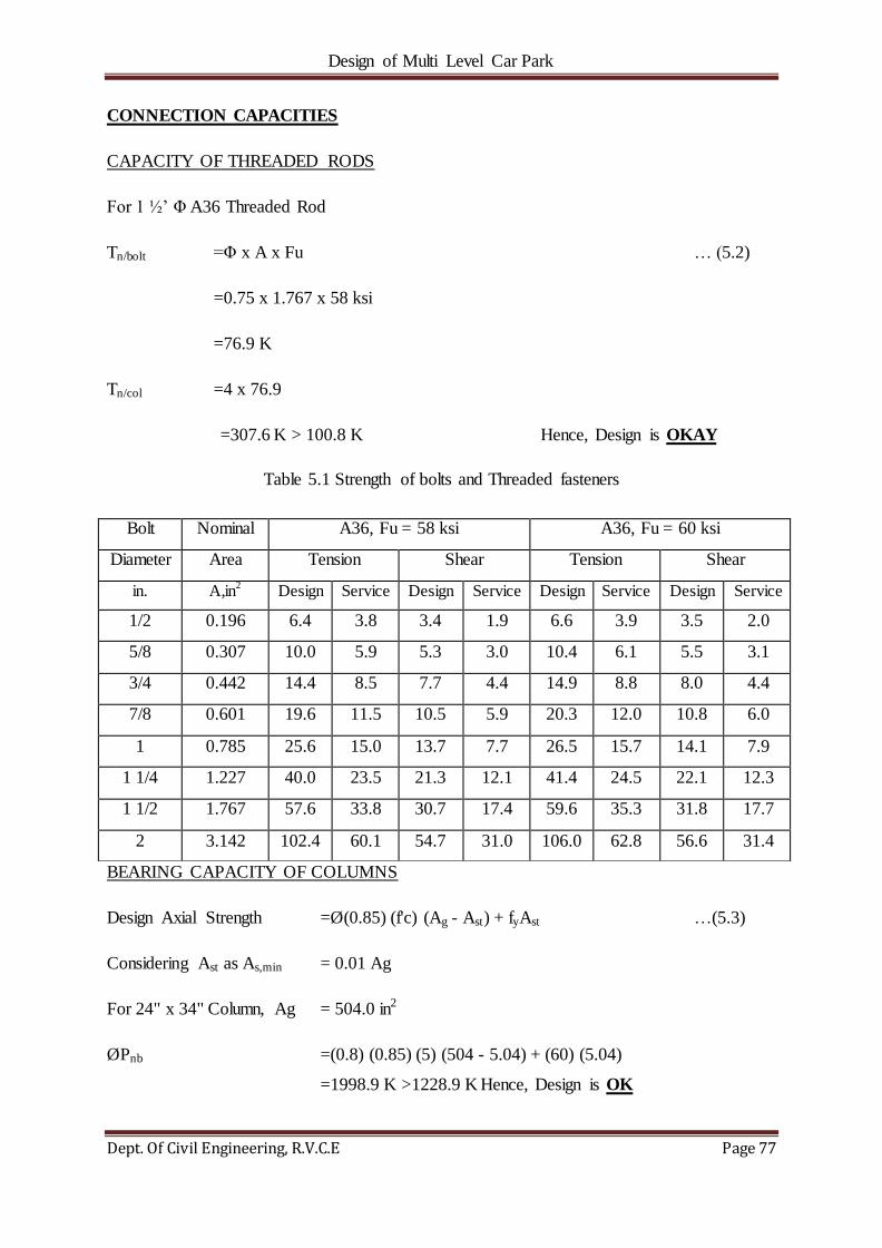
Design of Multi Level Car Park
Dept. Of Civil Engineering, R.V.C.E Page 77
CONNECTION CAPACITIES
CAPACITY OF THREADED RODS
For 1 ½‘ Φ A36 Threaded Rod
Tn/bolt =Φ x A x Fu … (5.2)
=0.75 x 1.767 x 58 ksi
=76.9 K
Tn/col =4 x 76.9
=307.6 K > 100.8 K Hence, Design is OKAY
Table 5.1 Strength of bolts and Threaded fasteners
BEARING CAPACITY OF COLUMNS
Design Axial Strength =Ø(0.85) (f'c) (Ag - Ast) + fyAst …(5.3)
Considering Ast as As,min = 0.01 Ag
For 24" x 34" Column, Ag = 504.0 in2
ØPnb =(0.8) (0.85) (5) (504 - 5.04) + (60) (5.04)
=1998.9 K >1228.9 K Hence, Design is OK
Bolt Nominal A36, Fu = 58 ksi A36, Fu = 60 ksi
Diameter Area Tension Shear Tension Shear
in. A,in2 Design Service Design Service Design Service Design Service
1/2 0.196 6.4 3.8 3.4 1.9 6.6 3.9 3.5 2.0
5/8 0.307 10.0 5.9 5.3 3.0 10.4 6.1 5.5 3.1
3/4 0.442 14.4 8.5 7.7 4.4 14.9 8.8 8.0 4.4
7/8 0.601 19.6 11.5 10.5 5.9 20.3 12.0 10.8 6.0
1 0.785 25.6 15.0 13.7 7.7 26.5 15.7 14.1 7.9
1 1/4 1.227 40.0 23.5 21.3 12.1 41.4 24.5 22.1 12.3
1 1/2 1.767 57.6 33.8 30.7 17.4 59.6 35.3 31.8 17.7
2 3.142 102.4 60.1 54.7 31.0 106.0 62.8 56.6 31.4
Design of Multi Level Car Park
Dept. Of Civil Engineering, R.V.C.E Page 78
5.1.2 DESIGN OF SHEAR WALL FOUNDATION CONNECTION
5.1.2.1 DESIGN OF SHEAR WALL FOUNDATION CONNECTIONS ALONG GRID
‘2’
CONNECTION LOADS
TENSION LOADS
Uplift at Ends of Shearwall, Tu =206.9 K (Refer section 4.2.3.1.2)
Use (6) #11's Bars ends, for Uplift
Tu/No. of Bars =206.9/6 K
=37.4 K
SHEAR LOADS
Shear: SW1 has Uplift/Tension, therefore the dead load on the compression side is permanent
and can be used to reduce the amount of shear friction reinforcement (per AC1 318-05
11.7.7)
Base Shear, Vu =417.2 K (Refer section 4.2.3.1.2)
ØVn (from DL on Comp. Side) = (0.9 - 0.2SDS)(0.5*Pdl)(m) … (5.4)
=199.6 K
Where, m =0.6
SDS =0.244
Pdl =736.8
ØVn (from #11's in shear friction) =(6) x 42.12 K
=252.7 K
Vu,rem./No. of Bars =229/6 K
=38.2 K
*Note: Vu,rem. = Vu - ØVn(from DL on Comp. Side)

Design of Multi Level Car Park
Dept. Of Civil Engineering, R.V.C.E Page 79
Fig. 5.2 Section of Shear Wall-Foundation Connection
Design of Multi Level Car Park
Dept. Of Civil Engineering, R.V.C.E Page 80
CONNECTION CAPCITIES
SHEAR CAPACITY
Using Shear Friction per PCI Design Handbook, 7th Edition m = 0.6
ØVn (Per #11 Bar) =(0.75) (60 ksi) (1.56 in2) (0.6)
=42.1 K> 38.2 K Hence, Design is OKAY
TENSION CAPACITY
ØTn (Per #11 Bar) =(0.9) (60 ksi) (1.56 in2)
=84.2 K> 37.4 K Hence, Design is OKAY
7.1.2.2 DESIGN OF SHEAR WALL FOUNDATION CONNECTIONS ALONG GRID
‘4’
CONNECTION LOADS
TENSION LOADS
Uplift at Ends of Shear wall, Tu =254.0 K (Refer section 4.2.3.2.2)
Use (6) #11's Bars ends, for Uplift
Tu/No. of bars =254.0/6 K
=42.3 K
SHEAR LOADS
Shear: SW2 has Uplift/Tension, therefore the dead load on the compression side is permanent
and can be used to reduce the amount of shear friction reinforcement (per AC1 318-05
11.7.7)
Base Shear, Vu =309.1 K (Refer section 4.2.3.2.2)
ØVn (from DL on Comp. Side) = (0.9 - 0.2SDS)(0.5*Pdl)(m) … (5.5)
=199.6 K
Where, m =0.6

Design of Multi Level Car Park
Dept. Of Civil Engineering, R.V.C.E Page 81
SDS =0.244
Pdl =736.8
ØVn (from #11's in shear friction) =(6) x 42.12 K
=252.7 K
Vu,rem./No. of Bars =120.9/6 K
=20.2 K
*Note: Vu,rem. = Vu - ØVn (from DL on Comp. Side) … (5.6)
CONNECTION CAPACITIES
SHEAR CAPACITY
Using Shear Friction per PCI Design Handbook, 7th Edition m = 0.6
ØVn (Per #11 Bar) = (0.75) (60 ksi) (1.56 in2) (0.6)
=42.1 K>20.2 K Hence, Design is OKAY
TENSION CAPACITY
ØTn (Per #11 Bar) = (0.9) (60 ksi) (1.56 in2)
=84.2 K>42.3 K Hence, Design is OKAY
Table 5.2 Equivalent Area of Corresponding Steel Bars
Diameter(in) Area(in2)
5 0.31
6 0.44
7 0.60
8 0.79
9 1.00
10 1.27
11 1.56
14 2.25

Design of Multi Level Car Park
Dept. Of Civil Engineering, R.V.C.E Page 82
5.2 DESIGN OF DOUBLE-TEE-SHEAR WALL CONNECTIONS
CONNECTION LOADS:
Table 5.3.Shear Loads in kips for each Shear walls at Corresponding Floor Levels for Shear
Wall at grid ‗2‘.
STORY CUM SHEAR
(Kips)
STORY SHEAR
Vu(Kips)
NO. OF
CONNECTIONS
VU/(No. of
Connections)
4 250.448 104.865 12 8.739
3 324.054 73.606 12 6.133
2 416.123 92.069 12 7.672
Table 5.4.Shear Loads in kips for each Shear walls at Corresponding Floor Levels for Shear
Wall at grid ‗4‘.
STORY CUM SHEAR
(Kips)
STORY SHEAR
Vu (Kips)
NO. OF
CONNECTIONS
VU/(No. of
Connections)
4 195.235 64.557 12 5.380
3 252.924 57.689 12 4.807
2 308.047 55.123 12 4.593
CONNECTION CAPACITY
Embed Plate in Double-Tee (Unistress STD Plate No. P108S2)
Shear taken by (2) 1/2" diameter studs
ØVn =15.30 kips
Eccentricity taken out by the #4 bars
ØTn = (0.9)*(0.2)*(60)*(1)
=10.80 kips

Design of Multi Level Car Park
Dept. Of Civil Engineering, R.V.C.E Page 83
Fig 5.3 Section of Double-Tee to Shear Wall Connection

Design of Multi Level Car Park
Dept. Of Civil Engineering, R.V.C.E Page 84
Tu =Vu x e/d … (5.7)
ØVn =ØTn (d/e) … (5.8)
= (10.8 kips)(8")/4.75
= 18.19 kips
Fig 5.4 Embed Plate in Double-Tee
Embed Plate in Shearwall (Dayton Superior - P38 Slotted Corewall Insert II)
ØVn = 8.7 * 3 * .75
= 19.6 K
Strap Plate for Insert (JVI PSA Strap Anchor 2" wide x 8" long with e = 3")
ØVn = 11.3 K Controls Shear
Since Shear Capacity, 11.3 K > Connection Load, 8.739 K, Design is OKAY
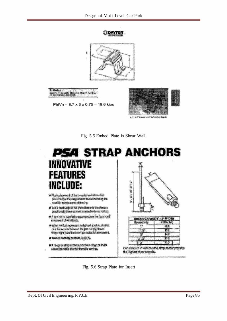
Design of Multi Level Car Park
Dept. Of Civil Engineering, R.V.C.E Page 85
Fig. 5.5 Embed Plate in Shear Wall.
Fig. 5.6 Strap Plate for Insert

Design of Multi Level Car Park
Dept. Of Civil Engineering, R.V.C.E Page 86
CHAPTER 6
GRAVITY ANALYSIS OF PRE-CAST/PRE-STRESSED COMPONENTS
6.1 DESIGN OF DOUBLE-TEE SECTIONS USING PRESTO
6.1.1 DESIGN OF DOUBLE-TEE FLANGE CONNECTION FOR END CONDITION
DESIGN DATA INPUT:
Thickness of Precast Flange, tf =4.000in.
Depth to Flange Steel, d =2in.
Length of Cantilever, Lc =3.13ft.
Distance between Stems, S =6.3ft
Influence Angle, θ =60.0˚ (Per PCI 7th Edition, Chapter 5, Section
5.12.1. research suggests an influence angle of
60˚ results in an effective width consistent with
crack patterns from actual load tests.)
Concentrated Load - Loaded Area Length, x =4.50in.
Concentrated Load - Loaded Area Width, y =4.50in.
Distributed Live Load, wLL =0.04ksf
Distributed Snow Load, wSL =0.0336ksf
Concentrated Load, P =2.00kips (Since some of the concentrated load
is shared by adjacent DT through flange/chord
connection 70% of3K = 2K of concentrated load
is considered.)
Concrete Strength, f'c =6.0ksi
Mesh Steel Yield Strength, fy =60.0ksi
Weight of Precast Flange Concrete, wt =0.15kcf

Design of Multi Level Car Park
Dept. Of Civil Engineering, R.V.C.E Page 87
Width of Design Section, b =1ft
Strength Reduction Factor, Φ =0.9
LOAD AT THE END OF DOUBLE-TEE (CORNER CONDITION)
Fig 6.1 Load Distributions at the cantilever portion of the Double-Tee
Self-weight of Precast Flange = (tf/12) * wt … (6.1)
= (4/12)*0.15
=WDL, TOTAL
=0.050 ksf
Effective Width of Cantilever, E = tanθ(Lc-(0.5x/12)) + (y/12) … (6.2)
=tan60(3.125-(2.25/12)) + (4.5/12)
=5.46ft.
LOAD CONDITION #1 -Self Weight + Concentrated Load, P
Mu,DL =1.2(WDL,TOTAL*Lc*Lc/2*12) … (6.3)
=1.2*(0.05*3.125*(3.125/2)*12)
=3.52k-in/ft
Mu,LL =1.6((P*Lc*12)/E)
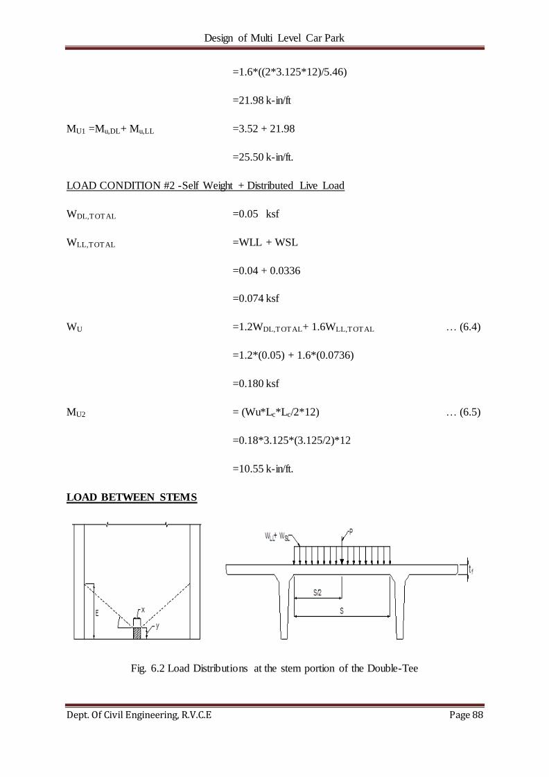
Design of Multi Level Car Park
Dept. Of Civil Engineering, R.V.C.E Page 88
=1.6*((2*3.125*12)/5.46)
=21.98 k-in/ft
MU1 =Mu,DL+ Mu,LL =3.52 + 21.98
=25.50 k-in/ft.
LOAD CONDITION #2 -Self Weight + Distributed Live Load
WDL,TOTAL =0.05 ksf
WLL,TOTAL =WLL + WSL
=0.04 + 0.0336
=0.074 ksf
WU =1.2WDL,TOTAL+ 1.6WLL,TOTAL … (6.4)
=1.2*(0.05) + 1.6*(0.0736)
=0.180 ksf
MU2 = (Wu*Lc*Lc/2*12) … (6.5)
=0.18*3.125*(3.125/2)*12
=10.55 k-in/ft.
LOAD BETWEEN STEMS
Fig. 6.2 Load Distributions at the stem portion of the Double-Tee
Design of Multi Level Car Park
Dept. Of Civil Engineering, R.V.C.E Page 89
LOAD CONDITION #3 -Self Weight + Concentrated Load, P
Mu,DL =1.2(WDL,TOTAL*S2/8*12) … (6.6)
=1.2*(0.05*(6.25^2/8)*12)
=3.52 k-in/ft
Mu,LL =1.6((P*S*12)/4E) … (6.7)
=1.6*((2*6.25*12)/(4*5.46))
=10.99 k-in/ft
MU3 = Mu,DL + Mu,LL =3.52 + 10.99
=14.51 k-in/ft
LOAD CONDITION #4 -Self Weight + Distributed Live Load
WDL,TOTAL =0.050 ksf
WLL,TOTAL =0.074 ksf
WU =0.180 ksf
MU4 = (Wu*S2/8*12) … (6.8)
=0.18*(6.25^2/8) *12
=10.55 k-in/ft
Determine Area of Steel Required for 1' Width of Flange
MU1 =25.50 k-in/ft.
MU2 =10.55 k-in/ft. Max Mu = 25.50 k-in/ft.
MU3 =14.51 k-in/ft.
MU4 =10.55 k-in/ft.

Design of Multi Level Car Park
Dept. Of Civil Engineering, R.V.C.E Page 90
ΦMn =ΦAsfy (d - (Asfy/1.7bf'c)) … (6.9)
= (ΦAs2fy2/1.7bf'c) - ΦAsfyd + Mu = 0
Using the Quadratic Equation, As = √
… (6.10)
= √
=3.83in2/ft or 0.25in2/ft
Therefore required As is 0.25 in2/ft
Thus, Provide WWR 12x4 - d4.0 x d4.5 (equivalent area=0.135 in2/ft) mesh throughout
the length of the tee and provide (1) #4 (equivalent area=0.2 in2/ft) at the ends of the
double tees.
Provided As =0.34 in2/ft.>0.25 in2/ft. OK
ΦMn = (0.9*0.34*60)(2-(0.34*60)/(1.7*6*12))
=33.66 k-in/ft. > Max Mu =25.50 k-in/ft OK
6.1.2 DESIGN OF DOOUBLE-TEE FLANGE CONNECTION FOR INTERIOR
CONDITION
DESIGN DATA INPUT:
Thickness of Precast Flange, tf =4.000in.
Depth to Flange Steel, d =2in.
Length of Cantilever, Lc =3.13ft.
Distance between Stems, S =6.3ft
Influence Angle, θ =60.0˚ (Per PCI 7th Edition, Chapter 5, Section
5.12.1. research suggests an influence angle of
60˚ results in an effective width consistent with
crack patterns from actual load tests.)

Design of Multi Level Car Park
Dept. Of Civil Engineering, R.V.C.E Page 91
Concentrated Load - Loaded Area Length, x =4.50in.
Concentrated Load - Loaded Area Width, y =4.50in.
Distributed Live Load, wLL =0.04ksf
Distributed Snow Load, wSL =0.0336ksf
Concentrated Load, P =3.00kips
Concrete Strength, f'c =6.0ksi
Mesh Steel Yield Strength, fy =60.0ksi
Weight of Precast Flange Concrete, wt =0.15kcf
Width of Design Section, b =1ft
Strength Reduction Factor, Φ =0.9
LOAD AT THE END OF DOUBLE-TEE (CORNER CONDITION)
Fig.6.3 Load Distributions at the cantilever portion of the Double-Tee.
Self-weight of Precast Flange = (tf/12) * wt … (6.11)
= (4/12)*0.15
=WDL, TOTAL
=0.050 ksf

Design of Multi Level Car Park
Dept. Of Civil Engineering, R.V.C.E Page 92
Effective Width of Cantilever, E = 2tanθ(Lc-(0.5x/12)) + (y/12) … (6.12)
= 2tan60(3.125-(2.25/12)) + (4.5/12)
= 10.55ft.
LOAD CONDITION #1 -Self Weight + Concentrated Load, P
Mu,DL =1.2(WDL,TOTAL*Lc*Lc/2*12) … (6.13)
=1.2*(0.05*3.125*(3.125/2)*12)
=3.52k-in/ft
Mu,LL =1.6((P*Lc*12)/E)
=1.6*(((3/2*3.125*12)/10.55)
=21.98 k-in/ft
MU1 =Mu,DL+ Mu,LL =3.52 + 8.53
=12.05 k-in/ft.
LOAD CONDITION #2 -Self Weight + Distributed Live Load
WDL,TOTAL =0.05 ksf
WLL,TOTAL =WLL + WSL
=0.04 + 0.0336
=0.074 ksf
WU =1.2WDL,TOTAL+ 1.6WLL,TOTAL
=1.2*(0.05) + 1.6*(0.0736)
=0.180 ksf
MU2 = (Wu*Lc*Lc/2*12)
=0.18*3.125*(3.125/2)*12
=10.55 k-in/ft.

Design of Multi Level Car Park
Dept. Of Civil Engineering, R.V.C.E Page 93
LOAD BETWEEN STEMS
Fig. 6.4 Load Distributions at the stem portion of the Double-Tee
LOAD CONDITION #3 -Self Weight + Concentrated Load, P
Mu,DL =1.2(WDL,TOTAL*S2/8*12) … (6.14)
=1.2*(0.05*(6.25^2/8)*12)
=3.52 k-in/ft
Mu,LL =1.6((P*S*12)/4E) … (6.15)
=1.6*((3*6.25*12)/(4*10.55))
=8.53 k-in/ft
MU3 = Mu,DL + Mu,LL =3.52 + 8.53
=12.05 k-in/ft
LOAD CONDITION #4 -Self Weight + Distributed Live Load
WDL,TOTAL =0.050 ksf
WLL,TOTAL =0.074 ksf
WU =0.180 ksf
MU4 = (Wu*S2/8*12) … (6.16)

Design of Multi Level Car Park
Dept. Of Civil Engineering, R.V.C.E Page 94
=0.18*(6.25^2/8) *12
=10.55 k-in/ft.
Determine Area of Steel Required for 1' Width of Flange
MU1 =12.05 k-in/ft.
MU2 =10.55 k-in/ft. Max Mu = 12.05 k-in/ft.
MU3 =12.05 k-in/ft.
MU4 =10.55 k-in/ft.
ΦMn = ΦAsfy (d - (Asfy/1.7bf'c)) … (6.17)
= (ΦAs2fy2/1.7bf'c) - ΦAsfyd + Mu = 0
Using the Quadratic Equation, As = √
… (6.18)
= √
=3.97in2/ft. or 0.11in2/ft.
Therefore required As is 0.11 in2/ft.
Thus, Provide WWR 12x4 - D4.0 x D4.5 (equivalent area=0.135 in2/ft) mesh throughout
the length of the tee
Provided As =0.14 in2/ft>0.11 in2/ft OK
ΦMn = (0.9*0.14*60)(2-(0.14*60)/(1.7*6*12))
=14.60 k-in/ft > Max Mu =12.05 k-in/ft OK

Design of Multi Level Car Park
Dept. Of Civil Engineering, R.V.C.E Page 95
6.2 DESIGN OF INVERTED-TEE BEAM SECTIONS USING PRESTO
6.2.1 DESIGN OF INVERTED-TEE BEAMS FOR THE ROOF LEVEL
ITB is located Along Grid 'B' and b/w Grids '1' & '2' at Roof Level with a Span of 39'-10‘.
Fig. 6.5 ITB Load Layout
Fig. 6.6 C/S at A-A
Load Combination: 1.2DL + 1.0LL + 1.6SL Controls Design Bending
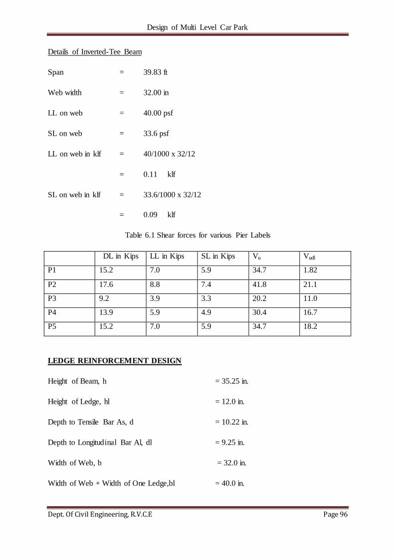
Design of Multi Level Car Park
Dept. Of Civil Engineering, R.V.C.E Page 96
Details of Inverted-Tee Beam
Span = 39.83 ft
Web width = 32.00 in
LL on web = 40.00 psf
SL on web = 33.6 psf
LL on web in klf = 40/1000 x 32/12
= 0.11 klf
SL on web in klf = 33.6/1000 x 32/12
= 0.09 klf
Table 6.1 Shear forces for various Pier Labels
DL in Kips LL in Kips SL in Kips Vu Vudl
P1 15.2 7.0 5.9 34.7 1.82
P2 17.6 8.8 7.4 41.8 21.1
P3 9.2 3.9 3.3 20.2 11.0
P4 13.9 5.9 4.9 30.4 16.7
P5 15.2 7.0 5.9 34.7 18.2
LEDGE REINFORCEMENT DESIGN
Height of Beam, h = 35.25 in.
Height of Ledge, hl = 12.0 in.
Depth to Tensile Bar As, d = 10.22 in.
Depth to Longitudinal Bar Al, dl = 9.25 in.
Width of Web, b = 32.0 in.
Width of Web + Width of One Ledge,bl = 40.0 in.
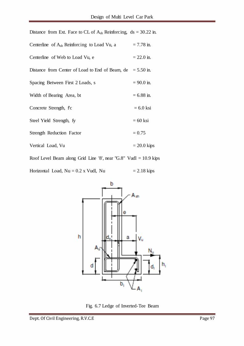
Design of Multi Level Car Park
Dept. Of Civil Engineering, R.V.C.E Page 97
Distance from Ext. Face to CL of Ash Reinforcing, ds = 30.22 in.
Centerline of Ash Reinforcing to Load Vu, a = 7.78 in.
Centerline of Web to Load Vu, e = 22.0 in.
Distance from Center of Load to End of Beam, de = 5.50 in.
Spacing Between First 2 Loads, s = 90.0 in.
Width of Bearing Area, bt = 6.88 in.
Concrete Strength, f'c = 6.0 ksi
Steel Yield Strength, fy = 60 ksi
Strength Reduction Factor = 0.75
Vertical Load, Vu = 20.0 kips
Roof Level Beam along Grid Line '8', near "G.8" Vudl = 10.9 kips
Horizontal Load, Nu = 0.2 x Vudl, Nu = 2.18 kips
Fig. 6.7 Ledge of Inverted-Tee Beam
Design of Multi Level Car Park
Dept. Of Civil Engineering, R.V.C.E Page 98
TRANSVERSE (CANTILEVER) BENDING OF THE LEDGE
AS,REQ'D = [1/Φfy] * [Vu(a/d) + Nu(hl/d)] … (6.19)
= 1/(0.75*60)*[20(7.78/10.22)+2.184(12/10.22)]
= 0.40 in2
Distribute Steel over a distance of
de + 6hl = 78''
de + s/2 = 50.5''
de + (bt + hl)/2 =14.9'' Controls … (6.20)
Therefore, AS,REQ'D =0.4/(14.9375/12)
=0.33 in²/ft.
PROVIDE #4 STIRRUPS at 6 in. O.C.
As(PROVD.) = (0.20/0.50)
= 0.40 in2/ft. >0.33 in2/ft.
HENCE O.K
LONGITUDINAL BENDING OF THE LEDGE
Al,REQ'D = 200 (bl - b) dl / fy … (6.21)
=[200*(40-32)(9.25/60)]/1000
= 0.25 in² for fy = 60 ksi
Al,REQ'D = 200 (bl - b) dl / fy … (6.22)
= [200*(40-32)(9.25/270)]/1000
= 0.06 in² for fy = 270 ksi
Therefore Provide (1) #5 Bar at Top & Bottom of Ledge
AL(PROVD.) = (0.31) (1) = 0.31 in2 > 0.25 in2 HENCE OK

Design of Multi Level Car Park
Dept. Of Civil Engineering, R.V.C.E Page 99
TORSION AND SHEAR REINFORCEMENT
TRANSVERSE REINFORCING:
1) (Av + 2At) REQ‘D from Presto run. = 0.28 in.2 / ft. … (6.23)
2) (Ash) REQ‘D (From Hanger Steel Req.) = 0.66in.2 / ft.
(0.33 in.2 / ft. x 2)
(Av + 2At)PROV'D = (0.2 x 2 x 12/6)
= 0.80 in2/ft. > 0.66 in2/ft.
HENCE O.K
Therefore Provide #4 Stirrups at 6" O.C.
LONGITUDINAL REINFORCING:
AL,REQ'Dfrom Presto = 6.83 in.2
Therefore Provide ( 6 ) #7 Hair Pins.
AL,PROV'D = (0.60) ( 6 ) ( 2 )
= 7.20 in.2 > 6.83 in.2 HENCE O.K.
Therefore Provide (6) #7 X 6'-0" Lg. U-Bars

Design of Multi Level Car Park
Dept. Of Civil Engineering, R.V.C.E Page 100
6.3 DESIGN OF SPANDREL SECTIONS USING PRESTO
Span of Spandrel – 44.92‘
Fig 6.8 Loads acting on the Spandrel
Fig. 6.9 C/S of the given spandrel
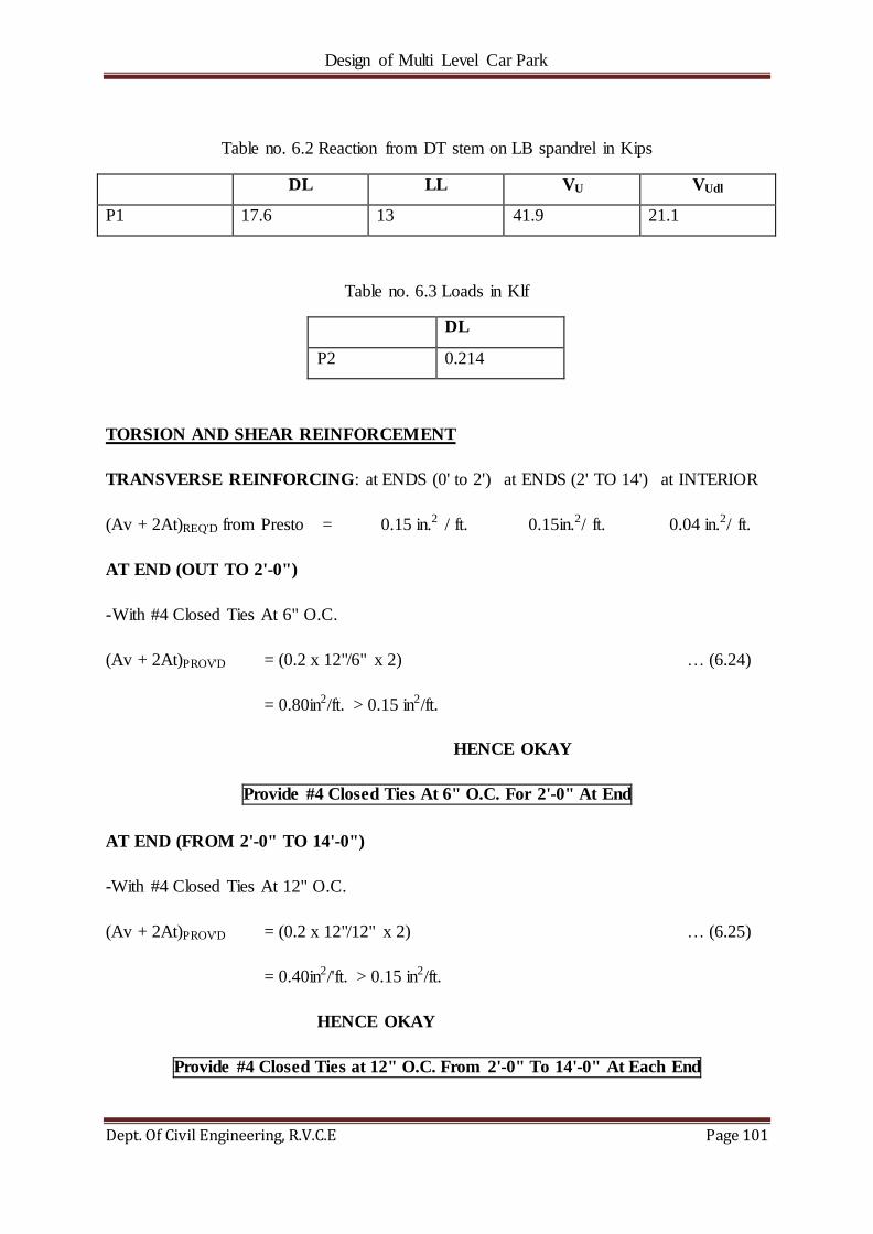
Design of Multi Level Car Park
Dept. Of Civil Engineering, R.V.C.E Page 101
Table no. 6.2 Reaction from DT stem on LB spandrel in Kips
DL LL VU VUdl
P1 17.6 13 41.9 21.1
Table no. 6.3 Loads in Klf
DL
P2 0.214
TORSION AND SHEAR REINFORCEMENT
TRANSVERSE REINFORCING: at ENDS (0' to 2') at ENDS (2' TO 14') at INTERIOR
(Av + 2At)REQ'D from Presto = 0.15 in.2 / ft. 0.15in.2/ ft. 0.04 in.2/ ft.
AT END (OUT TO 2'-0")
-With #4 Closed Ties At 6" O.C.
(Av + 2At)PROV'D = (0.2 x 12"/6" x 2) … (6.24)
= 0.80in2/ft. > 0.15 in2/ft.
HENCE OKAY
Provide #4 Closed Ties At 6" O.C. For 2'-0" At End
AT END (FROM 2'-0" TO 14'-0")
-With #4 Closed Ties At 12" O.C.
(Av + 2At)PROV'D = (0.2 x 12"/12" x 2) … (6.25)
= 0.40in2/'ft. > 0.15 in2/ft.
HENCE OKAY
Provide #4 Closed Ties at 12" O.C. From 2'-0" To 14'-0" At Each End

Design of Multi Level Car Park
Dept. Of Civil Engineering, R.V.C.E Page 102
AT MID-PORTION (BALANCE)
-With One Layer Of "Fm7" Mesh At Ext. Face And One Layer Of "Fm9" Mesh at Interior
Face (Both Have D7 Wires at 16" O.C. Max).
(Av + 2At)PROV'D = (0.07 x 12/16 x 2) = 0.11 in2/ft. > 0.04 in2/ft. … (6.26)
HENCE OKAY
Provide (1) Layer Of "Fm7" Mesh at Exterior Face And Provide (1) Layer Of "Fm9"
Mesh at Interior Face
LONGITUDINAL REINFORCING:
AT END:
AL,REQ'D from Presto run = 4.05 in2
Provide ( 5 ) #6 Hair Pins
AL,PROV'D = (0.44 ) ( 5 ) ( 2 )
=4.40 in.2> 4.05 in.2 HENCE OKAY.
AT MID PORTION:
AL ,REQ'D from Presto run =4.37 in2
Provide (10) #6 Continuous Bars
AL,PROV'D = ( 0.44 ) ( 10 )
= 4.40 in.2> 4.37 in.2
HENCE OKAY
Provide (5) #6 X 5'-0" Long. U-Bars with (10) #6 X Continuous Bars

Design of Multi Level Car Park
Dept. Of Civil Engineering, R.V.C.E Page 103
6.4 DESIGN OF COLUMN SECTIONS USING VERTEX
Fig. 6.10 Loading Diagram Fig. 6.11SectionA-A

Design of Multi Level Car Park
Dept. Of Civil Engineering, R.V.C.E Page 104
Fig. 6.12 Cross Section of Column
Table 6.4 Loads and Moment on P1 and P2
P1 P2
DL(Kips) 76.5 76.5
Mx(Kips-in) 1539.6 1539.6
Mz(Kips-in) 688.5 688.5
LL(Kips) 26.4 26.4
Mx(Kips-in) 531.3 531.3
Mz(Kips-in) 237.6 237.6
SL(Kips) 22.2 -
Mx(Kips-in) 446.8 -
Mz(Kips-in) 199.8 -
Vu(Kips) 153.7 134.0
Vudl(Kips-in) 91.8 91.8
24"
34
"+ Mx
X
ex=
9"
ex=
-9"
z
+ Mz
21
12"
12
12"
PK
T.
P1/P2P1/P2
ex=
9"
ex=
-9"
ez=
+2
01
8"
DESIGN
SECTION
TOP FACE
CL
CL
LEFT FACE

Design of Multi Level Car Park
Dept. Of Civil Engineering, R.V.C.E Page 105
According to IBC-2006 - Section 1605.2.1
Load Combinations:
1) 1.2 DL + 1.6 LL + 0.5 SL
2) 1.2 DL + 1.6 LL (Max. LL on one side) + 0.5 SL
3) 1.2 DL + 1.0 LL + 1.6 SL
4) 1.2 DL + 1.0 LL (Max. LL on one side) + 1.6 SL
MIN. / MAX COLUMN REINFORCEMENT (PER ACI SECTION 10.9.1)
Column Width = 24 in.
Column Depth = 21.5 in.
Gross Column Area (Ag) = 516.0 in.2
As min = 0.01 Ag
= 5.16 in2
As max = 0.08 Ag
= 41.28 in2
PROVIDE 4 #11 BARS
As,PROV'D = 4*1.56in2
=6.24 in2
As min < As PROV'D < As max HENCE O.K.
DETERMINE COLUMN TIE SPACING (PER ACI SECTION 7.10.5)
USING #11 LONGITUDINAL BARS
SPACING NOT TO EXCEED:
16 LONGITUDINAL BAR DIAMETERS =16 * 1.41in. =22.6in
Design of Multi Level Car Park
Dept. Of Civil Engineering, R.V.C.E Page 106
48 TIE BAR DIAMETERS = 48 *0.5 in. =24.0 in
LEAST DIMENSION OF THE COLUMN = 21.5 in. =21.5 in
SPACE# 4 TIES at 21'' MAX
6.5 DESIGN OF SHEAR WALL SECTIONS USING VERTEX
SW Design Approach Summary
This project was determined to be seismic design category 'B' and has a lateral force resisting
system that is defined as a "Bearing Wall System" comprised of "Intermediate Precast Shear
walls".
The Codes and Standards followed are IBC 2006[15] (New York State Building Code 2010),
ASCE 7-05[13]Per ACI 318-05[14], Section 21.1 as added by IBC 2006[15] Section
1908.1.3, the vertical elements of the Shear walls are permitted to be designed as "wall piers"
as long as they meet certain dimensional criteria. On this project all vertical elements shall be
designed as wall piers. Per ACI 318-05[14] Section 21.2.1.2, as modified by IBC 2006[15]
section 1908.1.4, for Seismic Design Category 'B' Structures, the vertical "wall pier" elements
and the solid portions above and below the openings may be designed and reinforced in
accordance with ACI 318-05[14] chapter 1 thru 18 and 22. Since the Shear walls are
considered as "Intermediate Precast Shear walls" and Structure falls within the Seismic
Design Category 'B' region, no special ductile detailing is required to be considered for the
design. The Shear walls are hence reinforced "nominally" to resist both Lateral and Gravity
loads. Below listed is the step by step approach.
Lateral Design:
Shear walls "SW1" & "SW2" are combined into a Single group since all of them support
same loadings. Critical SW among each group is designed for its Lateral Loadings by
designing their Vertical Column Strips as Wall piers. These Wall piers are adequately
designed to resist both Shear and Flexure due to Lateral Forces. Horizontal portions above
openings are designed to resist cumulative shear at given level and reinforced accordingly.
Gravity Design:
The most critical full-height "Pilaster section" is analysed for gravity loads.
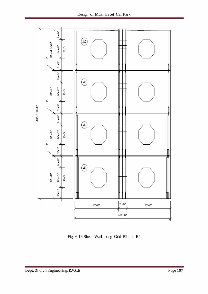
Design of Multi Level Car Park
Dept. Of Civil Engineering, R.V.C.E Page 107
Fig. 6.13 Shear Wall along Grid B2 and B4

Design of Multi Level Car Park
Dept. Of Civil Engineering, R.V.C.E Page 108
SHEARWALL DESIGN TO RESIST LATERAL LOADS
Shear wall Elevation for SW's at grid 'B/2' (Critical Case)
Fig 6.14 12‖ Shear Wall
Determine if Vertical Sections Can be Classified as Wall Piers
-Per IBC 2006, Section 1908.1:
Horizontal length-to-thickness ratio is between 2.5 and 6.
Clear height is at least two times the horizontal length.
at End Vertical Segments
Horizontal Length-to-Thickness Ratio = 5.00'/1.00‘ = 5.0 Consider as a Wall Pier
Clear Height-to-Length Ratio = 5.00'/5.00‘ =1.0 Conservatively consider as a Wall Pier
at Middle Vertical Segment
Horizontal Length-to-Thickness Ratio = 10.00'/1.00‘ = 10.0 Consider as a Wall
Clear Height-to-Length Ratio = 5.00'/10.00‘ = 0.5 Consider as a Wall
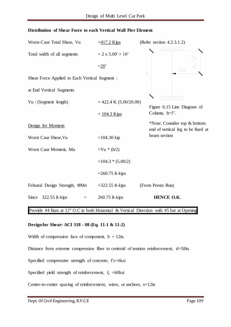
Design of Multi Level Car Park
Dept. Of Civil Engineering, R.V.C.E Page 109
Distribution of Shear Force to each Vertical Wall Pier Element
Worst-Case Total Shear, Vu =417.2 Kips (Refer section 4.2.3.1.2)
Total width of all segments = 2 x 5.00' + 10‘
=20‘
Shear Force Applied to Each Vertical Segment :
at End Vertical Segments
Vu / (Segment length) = 422.4 K (5.00/20.00)
= 104.3 Kips
Design for Moment:
Worst Case Shear,Vu =104.30 kip
Worst Case Moment, Mu =Vu * (h/2)
=104.3 * (5.00/2)
=260.75 ft-kips
Felxural Design Strength, ΦMn =322.55 ft-kips (From Presto Run)
Since 322.55 ft-kips > 260.75 ft-kips HENCE O.K.
Provide #4 Bars at 12" O.C in both Hoizontal & Vertical Direction with #5 bar at Opening
Design for Shear: ACI 318 - 08 (Eq. 11-1 & 11-2)
Width of compression face of component, b = 12in.
Distance from extreme compression fiber to centroid of tension reinforcement, d=58in.
Specified compressive strength of concrete, f‘c=6ksi
Specified yield strength of reinforcement, fy =60ksi
Center-to-center spacing of reinforcement, wires, or anchors, s=12in
Figure 6.15 Line Diagram of
Column, h=5‘.
*Note: Consider top & bottom
end of vertical leg to be fixed at
beam section

Design of Multi Level Car Park
Dept. Of Civil Engineering, R.V.C.E Page 110
Strength-reduction factor, Φ = 0.75
Worst Case Shear,Vu =105.60 kip
Factored Shear Strength, φVc =Φ *2*SQRT(f'c)*b*d … (6.27)
= 0.75 * 2 * SQRT(6000) * 12.00 * 58.00
=80.9 kips
Φ Vc / 2 =40.4 kips
Therefore, Vu > φVc
Hence, provide As,reqd to satisfy Vn = Vc + Vs, Av,min or (50*b*s)/fy
φVs,req'd = Vu - φVc … (6.28)
=105.6 - 80.87
=24.73 kips
Av,min =φ * SQRT(f'c) * ((b*s) / fy)
=0.75*SQRT(6000)*((12.00*12.0)/60000)
=0.14 in2/ft
or =(50 * b * s) / fy
=(50 *12.00 * 12.0) / 60000
=0.12 in2/ft
or =(Vs,req'd * s) / (φ * fy * d)
=(24.73 * 12.0) / (0.75 * 60 * 58.00)
Therefore Av,min =0.11 in2/ft.
Provide #4 Bars @ 12" O.C. in both Hoizontal & Vertical Direction which is =0.8 in2>.14 in2

Design of Multi Level Car Park
Dept. Of Civil Engineering, R.V.C.E Page 111
6.5 DESIGN OF LITE WALL SECTIONS USING VERTEX
This design type covers all horizontal litewalls along Grid "B"
Lite Wall Design Approach Summary
This project was determined to be seismic design category 'B' and has a lateral force resisting
system that is defined as a "Bearing Wall System" comprised of "Intermediate Precast
Shearwalls". The Codes and Standards followed are IBC 2006[4] (New York State Building
Code 2010), ASCE 7-05[13] Per ACI 318-05[14], Section 21.1 as added by IBC 2006[15]
Section 1908.1.3, the vertical elements of the Litewalls are permitted to be designed as "wall
piers" as long as they meet certain dimensional criteria. On this project all vertical elements
shall be designed as wall piers. Per ACI 318-05[14] Section 21.2.1.2, as modified by IBC
2006[15] section 1908.1.4, for Seismic Design Category 'B' Structures, the vertical "wall
pier" elements and the solid portions above and below the openings may be designed and
reinforced in accordance with ACI 318-05[14] chapter 1 thru 18 and 22. Since the Litewalls
are considered as "Intermediate Precast Shearwalls" and Structure falls within the Seismic
Design Category 'B' region, no special ductile detailing is required to be considered for the
design. The Litewalls are hence reinforced "nominally" to resist both Lateral and Gravity
loads. Below listed is the step by step approach.
Lateral Design:
Litewalls "LiteWalls1" & "LiteWalls2" are combined into a Single group since Both of them
support same loadings. Critical LW among each group is designed for its Lateral Loadings by
designing their Vertical Column Strips as Wall piers. These Wall piers are adequately
designed to resist both Shear and Flexure due to Lateral Forces.
Gravity Design:
The most critical full-height "column strip" is analyzed for gravity loads with Out-of-Plane
moments incombination with the seismic orthogonal (In-plane) moments at the top and
bottom of each vertical wall pier elements.
The elevation of a litewall is shown in Fig. 6.16.

Design of Multi Level Car Park
Dept. Of Civil Engineering, R.V.C.E Page 112
Fig. 6.16 LiteWall Elevation for LiteWall's along grids 'B' between grids '3' and '4'
Determine if Vertical Sections Can be Classified as Wall Piers
-Per IBC 2006, Section 1908.1:
Horizontal length-to-thickness ratio is between 2.5 and 6.
Clear height is at least two times the horizontal length.
at End Vertical Segments near Grid ‗3‘
Horizontal Length-to-Thickness Ratio = 5.46'/1.00‘ = 5.46 Consider as a Wall Pier
Clear Height-to-Length Ratio = 6.00'/5.46‘ =1.1 Conservatively consider as a Wall Pier
at Interior Vertical Segment
Horizontal Length-to-Thickness Ratio = 3.50'/1.00‘ = 3.5 Consider as a Wall Pier
Clear Height-to-Length Ratio = 6.00'/3.50‘ = 1.7 Conservatively consider as a Wall Pier
at End Vertical Segments near Grid ‗4‘
Horizontal Length-to-Thickness Ratio = 4.50'/1.00‘ = 4.5 Consider as a Wall Pier
Clear Height-to-Length Ratio = 6.00'/4.50‘ = 1.3 Conservatively consider as a Wall Pier

Design of Multi Level Car Park
Dept. Of Civil Engineering, R.V.C.E Page 113
Distribution of Shear Force to each Vertical Wall Pier Element
Worst-Case Total Shear, Vu =360.2 Kips (Refer section 4.2.2.2)
Total width of all segments = 4.5' + 4 x 3.5' + 5.46'
=23.96'
Shear Force Applied to Each Vertical Segment :
at End Vertical Segments near Grid ‗3‘
Vu / (Segment length) = 360.2 K (5.46/23.96)
= 72.9 Kips
at Interior Vertical Segment
Vu / (Segment length) = 360.2 K (3.5/23.96)
= 46.7 Kips
at End Vertical Segments near Grid ‗4‘
Vu / (Segment length) = 360.2 K (4.50/23.96) = 60 Kips
Wall Pier Design at End Vertical Segments near Grid ‘3’
Design for Moment:
Worst Case Shear,Vu =72.90 kip
Worst Case Moment, Mu =Vu * (h/2)
=72.90 * (5.00/2)
=218.70 ft-kips
Flexural Design Strength, ΦMn =265.15 ft-kips (From Presto Run)
Since 265.15 ft-kips > 218.70 ft-kips HENCE O.K.
Provide (2) #5 Bars at each side of wall pier and (2) #5 bar at Center
Fig. 6.17 Line Diagram of
Column, h=6‘.
*Note: Consider top &
bottom end of vertical leg to
be fixed at beam section
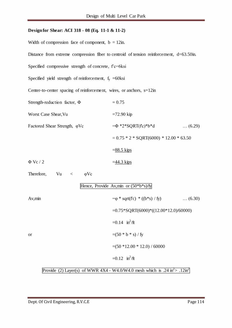
Design of Multi Level Car Park
Dept. Of Civil Engineering, R.V.C.E Page 114
Design for Shear: ACI 318 - 08 (Eq. 11-1 & 11-2)
Width of compression face of component, b = 12in.
Distance from extreme compression fiber to centroid of tension reinforcement, d=63.50in.
Specified compressive strength of concrete, f‘c=6ksi
Specified yield strength of reinforcement, fy =60ksi
Center-to-center spacing of reinforcement, wires, or anchors, s=12in
Strength-reduction factor, Φ = 0.75
Worst Case Shear,Vu =72.90 kip
Factored Shear Strength, φVc =Φ *2*SQRT(f'c)*b*d … (6.29)
= 0.75 * 2 * SQRT(6000) * 12.00 * 63.50
=88.5 kips
Φ Vc / 2 =44.3 kips
Therefore, Vu < φVc
Hence, Provide Av,min or (50*b*s)/fy
Av,min =φ * sqrt(f'c) * ((b*s) / fy) … (6.30)
=0.75*SQRT(6000)*((12.00*12.0)/60000)
=0.14 in2/ft
or =(50 * b * s) / fy
=(50 *12.00 * 12.0) / 60000
=0.12 in2/ft
Provide (2) Layer(s) of WWR 4X4 - W4.0/W4.0 mesh which is .24 in2> .12in2

Design of Multi Level Car Park
Dept. Of Civil Engineering, R.V.C.E Page 115
Wall Pier Design at Interior Segments
Design for Moment:
Worst Case Shear,Vu =46.70 kip
Worst Case Moment, Mu =Vu * (h/2)
=46.70 * (5.00/2)
=140.10 ft-kips
Felxural Design Strength, ΦMn =166.79 ft-kips (From Presto Run)
Since 166.79 ft-kips > 140.10 ft-kips HENCE O.K.
Provide (2) #5 Bars at each side of wall pier and (2) #5 bar at Center
Design for Shear: ACI 318 - 08 (Eq. 11-1 & 11-2)
Width of compression face of component, b = 12in.
Distance from extreme compression fiber to centroid of tension reinforcement, d=40in.
Specified compressive strength of concrete, f‘c=6ksi
Specified yield strength of reinforcement, fy =60ksi
Center-to-center spacing of reinforcement, wires, or anchors, s=12in
Strength-reduction factor, Φ = 0.75
Worst Case Shear,Vu =46.7 kip
Factored Shear Strength, φVc =Φ *2*SQRT(f'c)*b*d…(6.31)
= 0.75 * 2 * SQRT(6000) * 12.00 * 40
Fig 6.18 Line Diagram of
Column, h=6‘.
*Note: Consider top &
bottom end of vertical leg to
be fixed at beam section

Design of Multi Level Car Park
Dept. Of Civil Engineering, R.V.C.E Page 116
=55.8 kips
Φ Vc / 2 =27.9 kips
Therefore, Vu < φVc
Hence, Provide Av,min or (50*b*s)/fy
Av,min =φ * SQRT(f'c) * ((b*s) / fy) … (6.32)
=0.75*SQRT(6000)*((12.00*12.0)/60000)
=0.14 in2/ft
or =(50 * b * s) / fy
=(50 *12.00 * 12.0) / 60000
=0.12 in2/ft
Provide (2) Layer(s) of WWR 4X4 - W4.0/W4.0 mesh which is 0.24 in2> 0.12in2
Wall Pier Design at Interior Segments
Design for Moment:
Worst Case Shear,Vu =60.10 kip
Worst Case Moment, Mu =Vu * (h/2)
=60.10 * (5.00/2)
=180.30 ft-kips
Felxural Design Strength, ΦMn =217.02ft-kips (From Presto Run)
Since 217.02 ft-kips > 180.30 ft-kips HENCE O.K.
Provide (2) #5 Bars at each side of wall pier and (2) #5 bar at Center
Fig. 6.19 Line Diagram of
Column, h=6‘.
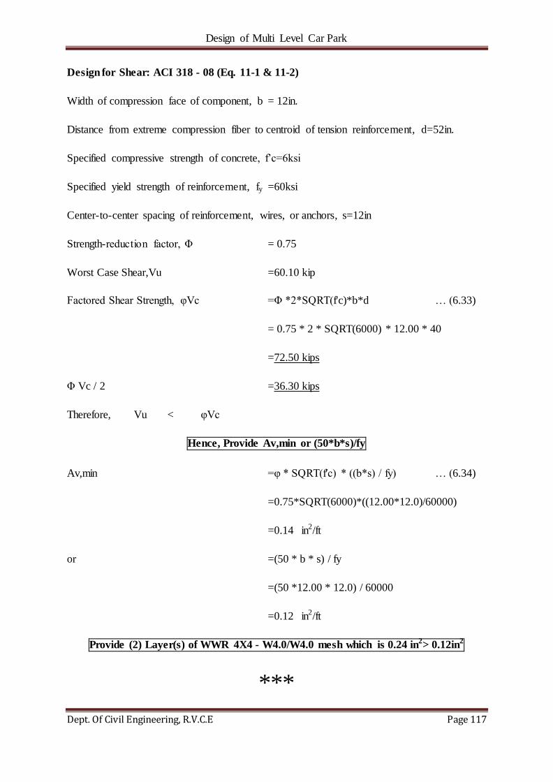
Design of Multi Level Car Park
Dept. Of Civil Engineering, R.V.C.E Page 117
Design for Shear: ACI 318 - 08 (Eq. 11-1 & 11-2)
Width of compression face of component, b = 12in.
Distance from extreme compression fiber to centroid of tension reinforcement, d=52in.
Specified compressive strength of concrete, f‘c=6ksi
Specified yield strength of reinforcement, fy =60ksi
Center-to-center spacing of reinforcement, wires, or anchors, s=12in
Strength-reduction factor, Φ = 0.75
Worst Case Shear,Vu =60.10 kip
Factored Shear Strength, φVc =Φ *2*SQRT(f'c)*b*d … (6.33)
= 0.75 * 2 * SQRT(6000) * 12.00 * 40
=72.50 kips
Φ Vc / 2 =36.30 kips
Therefore, Vu < φVc
Hence, Provide Av,min or (50*b*s)/fy
Av,min =φ * SQRT(f'c) * ((b*s) / fy) … (6.34)
=0.75*SQRT(6000)*((12.00*12.0)/60000)
=0.14 in2/ft
or =(50 * b * s) / fy
=(50 *12.00 * 12.0) / 60000
=0.12 in2/ft
Provide (2) Layer(s) of WWR 4X4 - W4.0/W4.0 mesh which is 0.24 in2> 0.12in2
***

Design of Multi Level Car Park
Dept. Of Civil Engineering, R.V.C.E Page 118
CHAPTER 7
CONCLUSION
7.1 CONCLUSION
The parking structure was analysed for lateral loads using ETABS. Shear walls and
diaphragms are designed to take up acting lateral forces. Lateral Analysis includes the
following-
o Overturning Analysis of Shear Walls
o Diaphragm Analysis
Connections are designed to connect separate components of the parking structure to
develop integrity of the structure. The connections designed are as follows-
o Double-Tee Shear Wall Connection
o Foundation Column Connection
o Shear Wall Foundation Connection
Individual components of the parking structure are designed using PRESTO and
VERTEX so that the moments developed in the elements are lesser than the moment
strength of the elements. The individual elements designed are as follows-
o Double-Tee Section
o Spandrels
o Inverted-Tee Beams
o Columns
o Shear Walls
o Lite Walls
***

Design of Multi Level Car Park
Dept. Of Civil Engineering, R.V.C.E Page 119
REFERENCES
[1] PCI Design Handbook-7TH EDITION published by PCI Industry Handbook Committee in U.S.A. in 2007.
[2] Michael Lepech, ―Sustainable Design and Manufacturing of Prefabricated Durable Infrastructure‖, CIFE proposal, Stanford, 2009.
[3] Kaar, P.H., L.B. Kriz, and E. Hognestad, ―Precast-Prestressed Concrete Bridges‖, 1. Pilot Tests of Continuous Girders. Journal of PCA Research and Development
Laboratories, 2(2), pp. 21–37, 1960.
[4] Mirmiran, A., S. Kulkarni, R. Miller, M. Hastak, B. Shahrooz, and R. Castrodale. ―Positive Moment Cracking in the Diaphragms of Simple-Span Prestressed Girders
Made Continuous.‖, American Concrete Institute, Detroit, pp.117–134, 2001.
[5] Mattock, A.H. and P.H. Kaar. ―Precast-prestressed Concrete Bridges III: Further Tests
of Continuous Girders‖. Journal of PCA Research and Development Laboratories,
2(3), pp. 51–78, 1960.
[6] ACI 318 ―Building Codes Requirement of Structural Concrete‖ published by American Institute Committee 318 in U.S.A. in 1977.
[7] ACI 318 ―Building Codes Requirement of Structural Concrete‖ published by
American Institute Committee 318 in U.S.A. in 2002.
[8] Ronald, H.D.‖ Design and Construction Considerations for Continuous Post-
tensioned Bulb Tee Girder Bridges‖. PCI Journal, Vol. 46, No. 3, pp. 44–66, 2001.
[9] Ng Ban Kiong, Zainal Abidin Akasah, ―An Overview Of Precast Concrete System
For Building Maintenance: Malaysian Perspective‖ Volume-2, Issue-6, 1684 – 1689,
2012.
[10] KSIIDC-IL&FS Project Development Company (KIPDC), ―Development Of Multi
Level Car Parking Facilities‖, 2009.
[11] Jack P. Moehle, Tony Ghodsi, John D. Hooper, David C. Fields, Rajnikanth Gedhada,
―Seismic Design of Cast-in-Place Concrete Special Structural Walls and Coupling
Beams.‖, NEHRP Seismic Design Technical Brief No. 6, 2006.
[12] Wan, G., R. B. Fleischman, and D. Zhang. "Effect of Spandrel Beam to Double Tee
Connection Characteristic on Flexure- Controlled Precast Diaphragms", Journal of
Structural Engineering, 2012.

Design of Multi Level Car Park
Dept. Of Civil Engineering, R.V.C.E Page 120
[13] ASCE-07 ―Minimum Design Load For Building And Other Structure‖ published by American Society for Civil Engineers in U.S.A. in 2005.
[14] ACI 318 ―Building Codes Requirement Of Structural Concrete‖ published by American Institute Committee 318 in U.S.A. in 2008.
[15] IBC-2006 ―Design Standardization‖ published by International Code Councilin U.S.A. in 2006.
[16] Ghosh, S.K. and A. W. DomelJr..―Design of Concrete Buildings for Earthquake and
Wind Forces‖ .Skokie, IL: Portland Cement Association, 1992.
[17] Abdel-Karim, A. M., and Maher K. Tadros. ―Stretched-Out Precast Concrete I-Girder
Bridge Spans. Concrete International‖, V. 13, No. 9, September, 1991.
[18] World Commission on Environment and Development, ―Report on Our Common
Future,‖ Oxford University Press, New, York, NY, 1987.
[19] Jorge Gutierrez, ―Reglamento de Diseño Estructuralpara la República de Panamá‖
REP-2003 (―Structural Design Code for the Republic of Panama‖), 2003.
[20] J. Humar and M.A. Mahgoub, ―Determination of seismic design forces by equivalent
static load method‖, Department of Civil and Environmental Engineering, Carleton
University,1125 Colonel By Drive, Ottawa, ON K1S 5B6, Canada, 2006.
[21] Timothy P. McCormick, ―Shear Walls‖, Seismic Retrofit Training, 2000.
[22] N Krishna Raju, ―Pre-Stressed Concrete‖, Tata Mcgraw Hill Publishing Company, 4th
Edition, 2007.
[23] Gawade S.S. &Chawan D.S., ―Load-deflection analysis of flat & corrugated stainless
steel diaphragms by theoretical & finite element method‖, International Journal of
Engineering Research and Applications, Vol. 3, Issue 4, Jul-Aug 2013, pp.799—802.
[24] Jingyao Zhang, Makoto Ohsaki and Atsushi Uchida, ―Equivalent Static Loads For
Nonliner Seismic Design Of Spatial Structures‖, World Conference on Earthquake
Engineering, October 12-17, 2008, Beijing, China.
[25] David T. Finley, Ricky A. Cribbs, ―Equivalent Static vs. Response Spectrum A
Comparison of Two Methods‖, HLA Engineers, Inc., 7267 Envoy Ct., Dallas, TX,
USA 75247.
[26] Philip Line, William L. Coulbourne, ―ASCE 7-10 Wind Provisions and Effects on
Wood Design and Construction‖, 2008.
Design of Multi Level Car Park
Dept. Of Civil Engineering, R.V.C.E Page 121
[27] Anil K Chopra, ―Dynamics of Structures‖, Pearson, Prentice Hall, 3rd Edition, 2007.
***
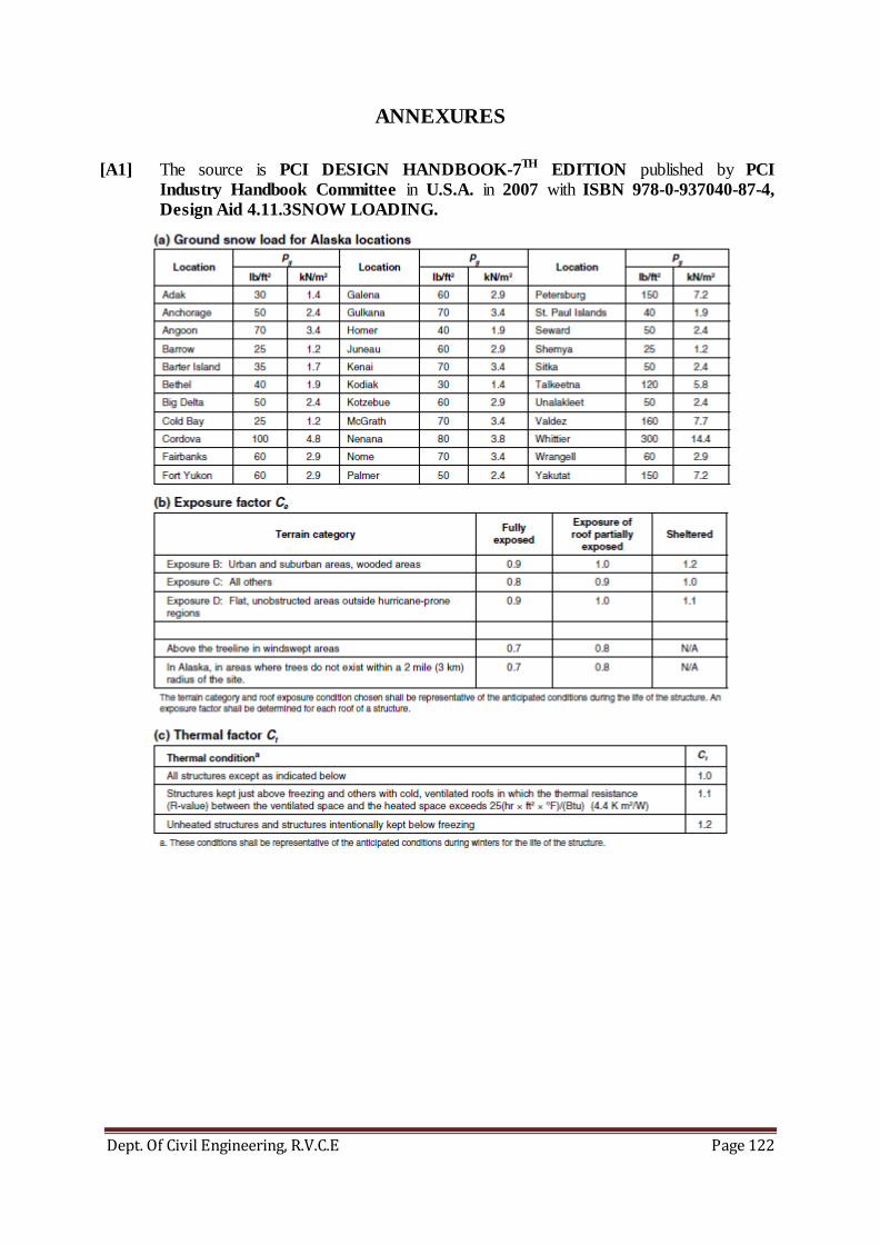
Design of Multi Level Car Park
Dept. Of Civil Engineering, R.V.C.E Page 122
ANNEXURES
[A1] The source is PCI DESIGN HANDBOOK-7TH EDITION published by PCI
Industry Handbook Committee in U.S.A. in 2007 with ISBN 978-0-937040-87-4,
Design Aid 4.11.3SNOW LOADING.
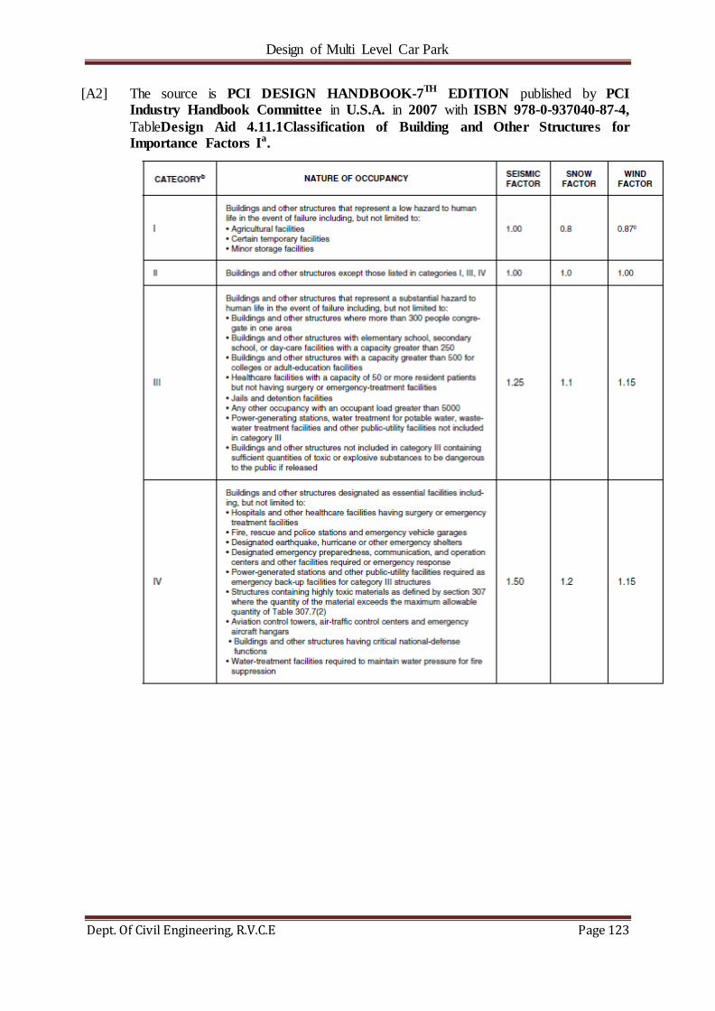
Design of Multi Level Car Park
Dept. Of Civil Engineering, R.V.C.E Page 123
[A2] The source is PCI DESIGN HANDBOOK-7TH EDITION published by PCI
Industry Handbook Committee in U.S.A. in 2007 with ISBN 978-0-937040-87-4,
TableDesign Aid 4.11.1Classification of Building and Other Structures for
Importance Factors Ia.

Design of Multi Level Car Park
Dept. Of Civil Engineering, R.V.C.E Page 124
[A3] The source is PCI DESIGN HANDBOOK-7TH EDITION published by PCI
Industry Handbook Committee in U.S.A. in 2007 with ISBN 978-0-937040-87-4,
TableDesign Aid 4.11.5Basic Wind Speed, mph (m/s).

Design of Multi Level Car Park
Dept. Of Civil Engineering, R.V.C.E Page 125
[A4] The source is PCI DESIGN HANDBOOK-7TH EDITION published by PCI
Industry Handbook Committee in U.S.A. in 2007 with ISBN 978-0-937040-87-4,
Table Design Aid 4.11.6 Factors for Use with ASCE 7-05 Method 1 Wind Design.

Design of Multi Level Car Park
Dept. Of Civil Engineering, R.V.C.E Page 126
[A5] The source is PCI DESIGN HANDBOOK-7TH EDITION published by PCI
Industry Handbook Committee in U.S.A. in 2007 with ISBN 978-0-937040-87-4,
Table Design Aid 4.11.7 Site Classifications and Coefficients.

Design of Multi Level Car Park
Dept. Of Civil Engineering, R.V.C.E Page 127
[A6] The source is PCI DESIGN HANDBOOK-7TH EDITION published by PCI
Industry Handbook Committee in U.S.A. in 2007 with ISBN 978-0-937040-87-4,
Table Design Aid 4.11.8 Design Coefficients and Factors for Precast Concrete
Seismic-Force-Resisting Systems.
***