design of machine structures topics
TRANSCRIPT
1
ME EN 7960 – Precision Machine Design – Design of Machine Structures 14-1
Design of Machine Structures
ME EN 7960 – Precision Machine DesignTopic 14
ME EN 7960 – Precision Machine Design – Design of Machine Structures 14-2
Topics
• Overall design approach for the structure• Stiffness requirements• Damping requirements• Structural configurations for machine tools• Other structural system considerations

2
ME EN 7960 – Precision Machine Design – Design of Machine Structures 14-3
Design Strategies
• Strategies for Accuracy:– Accuracy obtained from component accuracy
• Most machine tools are built this way– Accuracy obtained by error mapping
• Most coordinate measuring machines are built this way– Accuracy obtained from a metrology frame
• Special machines are built this way (usually one-of-a-kind cost-is-no-object machines)
• Kinematic design:– Deterministic– Less reliance on manufacturing– Stiffness and load limited, unless pot in epoxy
ME EN 7960 – Precision Machine Design – Design of Machine Structures 14-4
Design Strategies (contd.)
• Elastically averaged design:– Non-deterministic– More reliance on manufacturing– Stiffness and load not limited
• Passive temperature control:– Minimize and isolate heat sources– Minimize coefficient of thermal expansion– Maximize thermal diffusivity– Insulate critical components– Use indirect lighting– Use PVC curtains to shield the machine from infrared sources
3
ME EN 7960 – Precision Machine Design – Design of Machine Structures 14-5
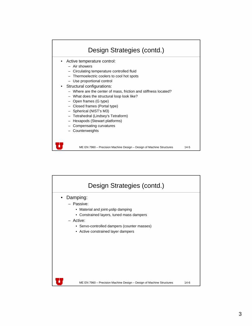
Design Strategies (contd.)• Active temperature control:
– Air showers– Circulating temperature controlled fluid– Thermoelectric coolers to cool hot spots– Use proportional control
• Structural configurations:– Where are the center of mass, friction and stiffness located?– What does the structural loop look like?– Open frames (G type)– Closed frames (Portal type)– Spherical (NIST's M3)– Tetrahedral (Lindsey's Tetraform)– Hexapods (Stewart platforms)– Compensating curvatures– Counterweights
ME EN 7960 – Precision Machine Design – Design of Machine Structures 14-6
Design Strategies (contd.)
• Damping:– Passive:
• Material and joint-µslip damping• Constrained layers, tuned mass dampers
– Active:• Servo-controlled dampers (counter masses)• Active constrained layer dampers

4
ME EN 7960 – Precision Machine Design – Design of Machine Structures 14-7
Summary of Strategies for Accuracy
• Accuracy obtained from component accuracy:– Inexpensive once the process is perfected– Accuracy is strongly coupled to thermal and mechanical loads on
the machine
• Accuracy obtained by error mapping:– Inexpensive once the process is perfected– Accuracy is moderately coupled to thermal and mechanical
loads on the machine
• Accuracy obtained from a metrology frame:– Expensive, but sometimes the only choice– Accuracy is uncoupled to thermal and mechanical loads on the
machine
ME EN 7960 – Precision Machine Design – Design of Machine Structures 14-8
Stiffness Requirements
• Engineers commonly ask "how stiff should it be?"• A minimum specified static stiffness is a useful but not
sufficient specification• Static stiffness and damping must be specified• Static stiffness requirements can be predicted• Damping can be specified and designed into a machine
5
ME EN 7960 – Precision Machine Design – Design of Machine Structures 14-9
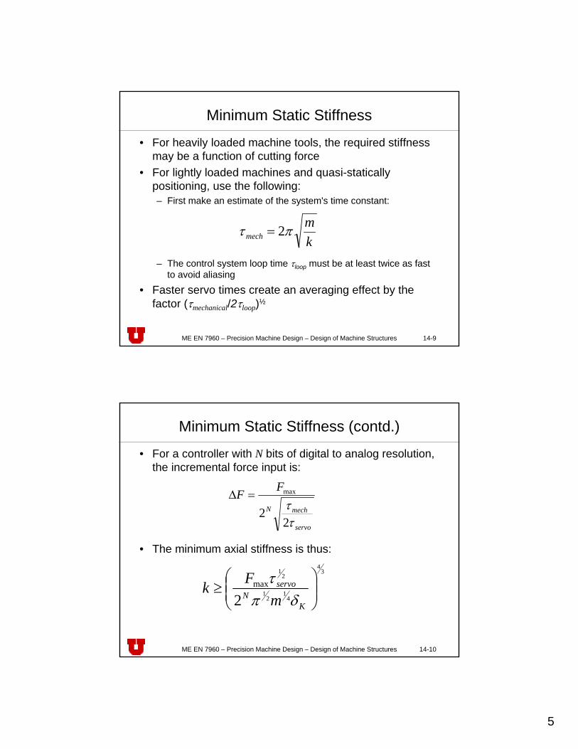
Minimum Static Stiffness
• For heavily loaded machine tools, the required stiffness may be a function of cutting force
• For lightly loaded machines and quasi-statically positioning, use the following:– First make an estimate of the system's time constant:
– The control system loop time τloop must be at least twice as fast to avoid aliasing
• Faster servo times create an averaging effect by the factor (τmechanical/2τloop)½
km
mech πτ 2=
ME EN 7960 – Precision Machine Design – Design of Machine Structures 14-10
Minimum Static Stiffness (contd.)
• For a controller with N bits of digital to analog resolution, the incremental force input is:
• The minimum axial stiffness is thus:
servo
mechN
FF
ττ2
2
max=Δ
34
41
21
21
2max
⎟⎟⎠
⎞⎜⎜⎝
⎛≥
KN
servo
mFk
δπτ
6
ME EN 7960 – Precision Machine Design – Design of Machine Structures 14-11
Minimum Static Stiffness (contd.)
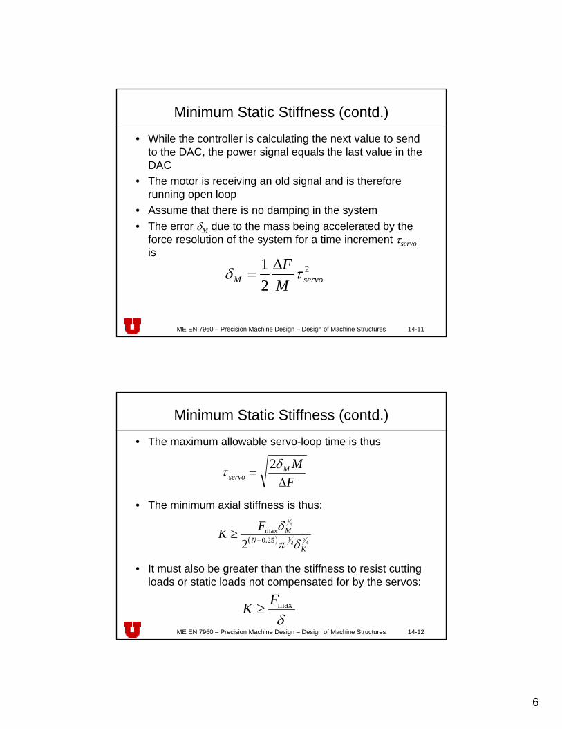
• While the controller is calculating the next value to send to the DAC, the power signal equals the last value in the DAC
• The motor is receiving an old signal and is therefore running open loop
• Assume that there is no damping in the system• The error δM due to the mass being accelerated by the
force resolution of the system for a time increment τservois
2
21
servoM MF τδ Δ
=
ME EN 7960 – Precision Machine Design – Design of Machine Structures 14-12
Minimum Static Stiffness (contd.)
• The maximum allowable servo-loop time is thus
• The minimum axial stiffness is thus:
• It must also be greater than the stiffness to resist cutting loads or static loads not compensated for by the servos:
FMM
servo Δ=
δτ 2
( ) 45
21
41
25.0max
2 KN
MFKδπ
δ−
≥
δmaxFK ≥
7
ME EN 7960 – Precision Machine Design – Design of Machine Structures 14-13
Minimum Static Stiffness (contd.)
• The maximum servo-loop time is thus:
• Typically, one would set δK = δM = ½δservo
• Usually, τservo actual = τservo /L, where L is the number of past values used in a recursive digital control algorithm
• Example: Required static stiffness for a machine with 800 N max. axial force, 250 kg system mass, and 14 bit DAC:
( )
max
75.0 41
43
21 2
Fm KM
N
servoδδπτ
+
≤
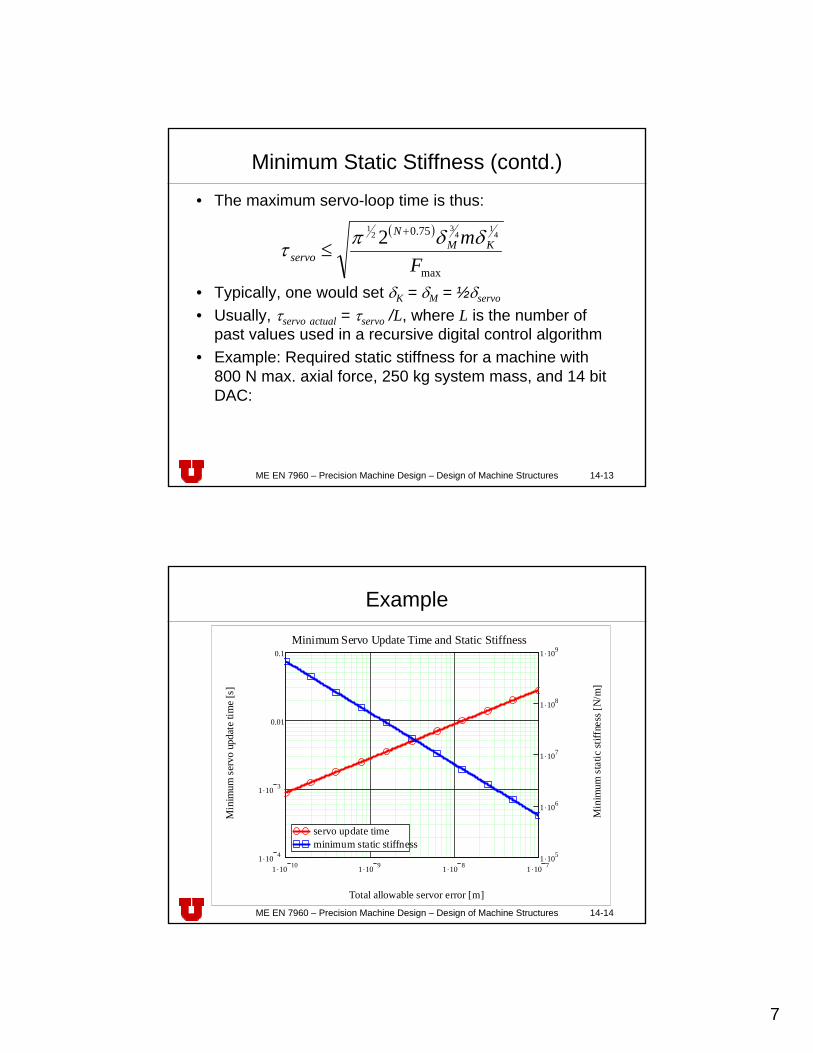
ME EN 7960 – Precision Machine Design – Design of Machine Structures 14-14
Example
1 .10 10 1 .10 9 1 .10 8 1 .10 71 .10 4
1 .10 3
0.01
0.1
1 .105
1 .106
1 .107
1 .108
1 .109
servo update timeminimum static stiffness
Minimum Servo Update Time and Static Stiffness
Total allowable servor error [m]
Min
imum
serv
o up
date
tim
e [s
]
Min
imum
stat
ic st
iffne
ss [N
/m]
8
ME EN 7960 – Precision Machine Design – Design of Machine Structures 14-15
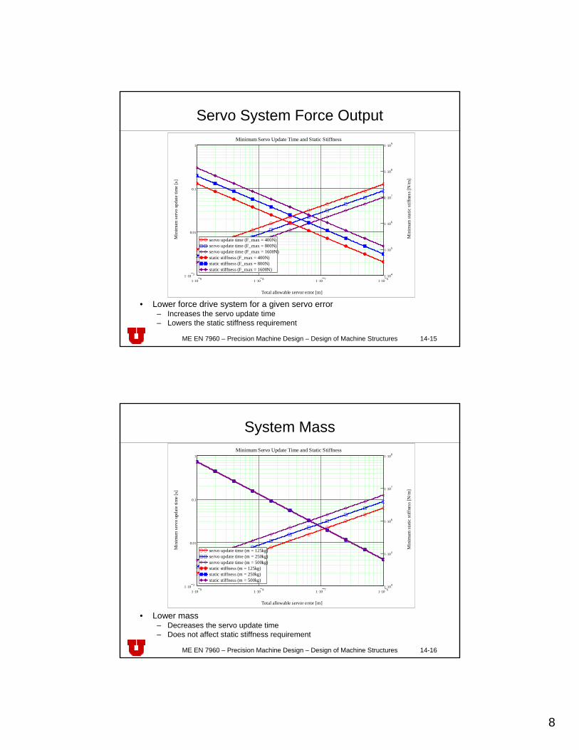
Servo System Force Output
• Lower force drive system for a given servo error– Increases the servo update time– Lowers the static stiffness requirement
1 .10 9 1 .10 8 1 .10 7 1 .10 61 .10 3
0.01
0.1
1
1 .104
1 .105
1 .106
1 .107
1 .108
1 .109
servo update time (F_max = 400N)servo update time (F_max = 800N)servo update time (F_max = 1600N)static stiffness (F_max = 400N)static stiffness (F_max = 800N)static stiffness (F_max = 1600N)
Minimum Servo Update Time and Static Stiffness
Total allowable servor error [m]
Min
imum
ser
vo u
pdat
e tim
e [s
]
Min
imum
sta
tic st
iffne
ss [N
/m]
ME EN 7960 – Precision Machine Design – Design of Machine Structures 14-16
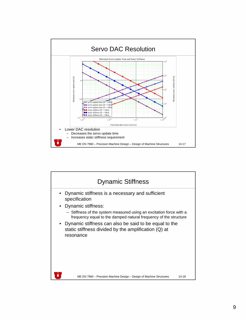
System Mass
• Lower mass– Decreases the servo update time– Does not affect static stiffness requirement
1 .10 9 1 .10 8 1 .10 7 1 .10 61 .10 3
0.01
0.1
1
1 .104
1 .105
1 .106
1 .107
1 .108
servo update time (m = 125kg)servo update time (m = 250kg)servo update time (m = 500kg)static stiffness (m = 125kg)static stiffness (m = 250kg)static stiffness (m = 500kg)
Minimum Servo Update Time and Static Stiffness
Total allowable servor error [m]
Min
imum
ser
vo u
pdat
e tim
e [s
]
Min
imum
sta
tic st
iffne
ss [N
/m]
9
ME EN 7960 – Precision Machine Design – Design of Machine Structures 14-17
Servo DAC Resolution
• Lower DAC resolution– Decreases the servo update time– Increases static stiffness requirement
1 .10 9 1 .10 8 1 .10 7 1 .10 61 .10 3
0.01
0.1
1
1 .104
1 .105
1 .106
1 .107
1 .108
servo update time (N = 12bit)servo update time (N = 14bit)servo update time (N = 16bit)static stiffness (N = 12bit)static stiffness (N = 14bit)static stiffness (N = 16bit)
Minimum Servo Update Time and Static Stiffness
Total allowable servor error [m]
Min
imum
ser
vo u
pdat
e tim
e [s
]
Min
imum
sta
tic st
iffne
ss [N
/m]
ME EN 7960 – Precision Machine Design – Design of Machine Structures 14-18
Dynamic Stiffness
• Dynamic stiffness is a necessary and sufficient specification
• Dynamic stiffness:– Stiffness of the system measured using an excitation force with a
frequency equal to the damped natural frequency of the structure
• Dynamic stiffness can also be said to be equal to the static stiffness divided by the amplification (Q) at resonance
10
ME EN 7960 – Precision Machine Design – Design of Machine Structures 14-19
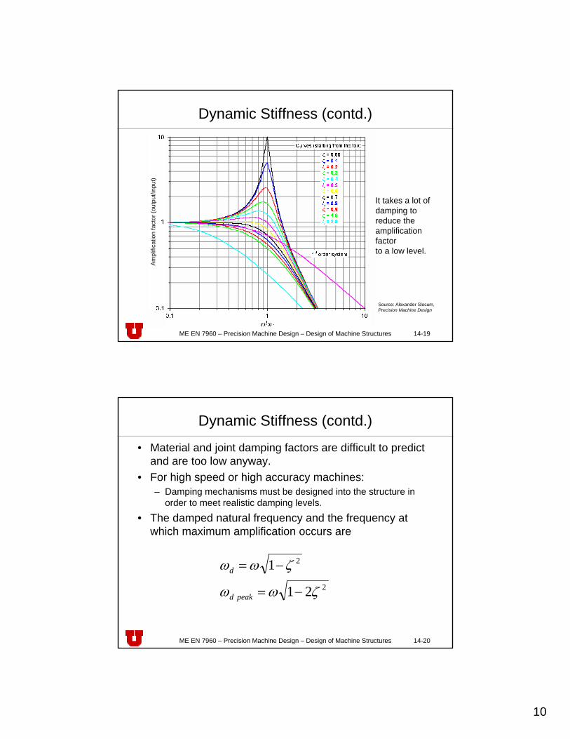
Dynamic Stiffness (contd.)
It takes a lot of damping to reduce the amplification factorto a low level.
Ampl
ifica
tion
fact
or (o
utpu
t/inp
ut)
Source: Alexander Slocum, Precision Machine Design
ME EN 7960 – Precision Machine Design – Design of Machine Structures 14-20
Dynamic Stiffness (contd.)
• Material and joint damping factors are difficult to predict and are too low anyway.
• For high speed or high accuracy machines:– Damping mechanisms must be designed into the structure in
order to meet realistic damping levels.
• The damped natural frequency and the frequency at which maximum amplification occurs are
2
2
21
1
ζωω
ζωω
−=
−=
peakd
d
11
ME EN 7960 – Precision Machine Design – Design of Machine Structures 14-21
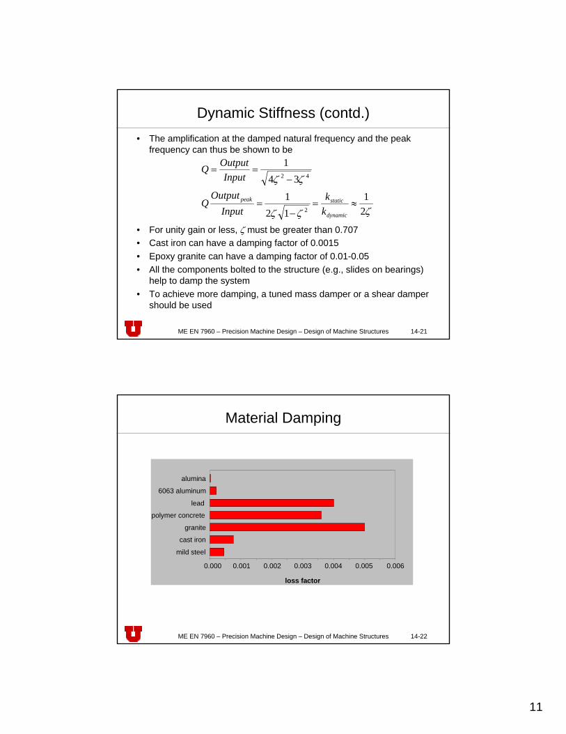
Dynamic Stiffness (contd.)• The amplification at the damped natural frequency and the peak
frequency can thus be shown to be
• For unity gain or less, ζ must be greater than 0.707• Cast iron can have a damping factor of 0.0015• Epoxy granite can have a damping factor of 0.01-0.05• All the components bolted to the structure (e.g., slides on bearings)
help to damp the system• To achieve more damping, a tuned mass damper or a shear damper
should be used
ζζζ
ζζ
21
121
341
2
42
≈=−
=
−==
dynamic
staticpeak
kk
InputOutput
Q
InputOutputQ
ME EN 7960 – Precision Machine Design – Design of Machine Structures 14-22
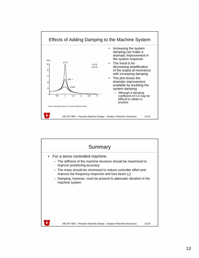
Material Damping
0.000 0.001 0.002 0.003 0.004 0.005 0.006
loss factor
granite
polymer concrete
lead
6063 aluminum
alumina
mild steel
cast iron

12
ME EN 7960 – Precision Machine Design – Design of Machine Structures 14-23
Effects of Changing System Mass• Adding mass:
– Adding sand or lead shot increases mass and damping via the particles rubbing on each other
– Higher mass slows the servo response, but helps attenuates high frequency noise
• Decreasing mass– Faster respond to command
signals– Increases a higher natural
frequency• Higher speed controller signals
must be used– Improved damping, a result of
the increased loss factor (the loss factor ζ = c/(2m)
– However, low mass systems show less noise rejection at higher frequencies
• This suggests that the machine will be less able to attenuate noise and vibration
m=2.0
m=1.0
m=0.5
c=0.2k=1.0
2
4
6
8
10H( )
0.5 1 1.5 2 2.5 3
Source: Alexander Slocum, Precision Machine Design
ME EN 7960 – Precision Machine Design – Design of Machine Structures 14-24
Effects of Adding Stiffness to the Machine System
• Higher stiffness gives a flatter response at low frequencies and give smaller displacements for a given force input
• The compromise of decreased noise attenuation is not as dramatic as is the case with lowering the system mass
– This is shown by the similar shapes in the three response curves at high frequencies
• This suggests that raising the stiffness of a system is always a desirable course of action
– However, acoustical noise may be worsened by adding stiffness (frequency of vibration is moved to the audible region of the human ear)
Source: Alexander Slocum, Precision Machine Design
13
ME EN 7960 – Precision Machine Design – Design of Machine Structures 14-25
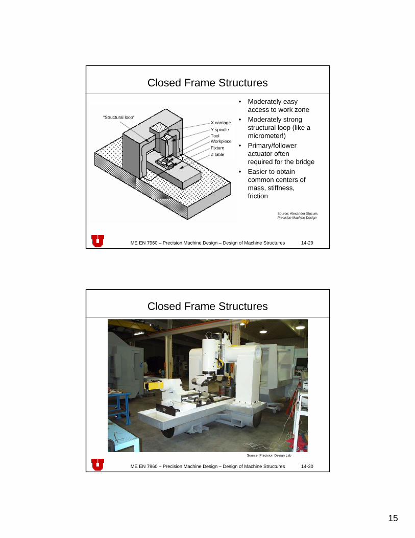
Effects of Adding Damping to the Machine System
• Increasing the system damping can make a dramatic improvement in the system response
• The trend is for decreasing amplification of the output at resonance with increasing damping
• The plot shows the dramatic improvement available by doubling the system damping:– Although a damping
coefficient of 0.4 may be difficult to obtain in practice
Source: Alexander Slocum, Precision Machine Design
ME EN 7960 – Precision Machine Design – Design of Machine Structures 14-26
Summary
• For a servo controlled machine:– The stiffness of the machine structure should be maximized to
improve positioning accuracy– The mass should be minimized to reduce controller effort and
improve the frequency response and loss factor (ζ) – Damping, however, must be present to attenuate vibration in the
machine system

14
ME EN 7960 – Precision Machine Design – Design of Machine Structures 14-27
SpindleToolWorkpieceFixtureX-Z table
“Structural loop”
Y X
Z
Open Frame Structures
• Easy access to work zone
• Structural loop prone to Abbeerrors (like calipers!)
Source: Alexander Slocum, Precision Machine Design
ME EN 7960 – Precision Machine Design – Design of Machine Structures 14-28
Open Frame Structures (contd.)
Spindle housing
Faceplate
Base
Carriage
Y2C
YR
XR
ZR
X2C
Z2C
Z2S
X2S
Y2S
Source: Alexander Slocum, Precision Machine Design
15
ME EN 7960 – Precision Machine Design – Design of Machine Structures 14-29
“Structural loop”X carriageY spindleToolWorkpieceFixtureZ table
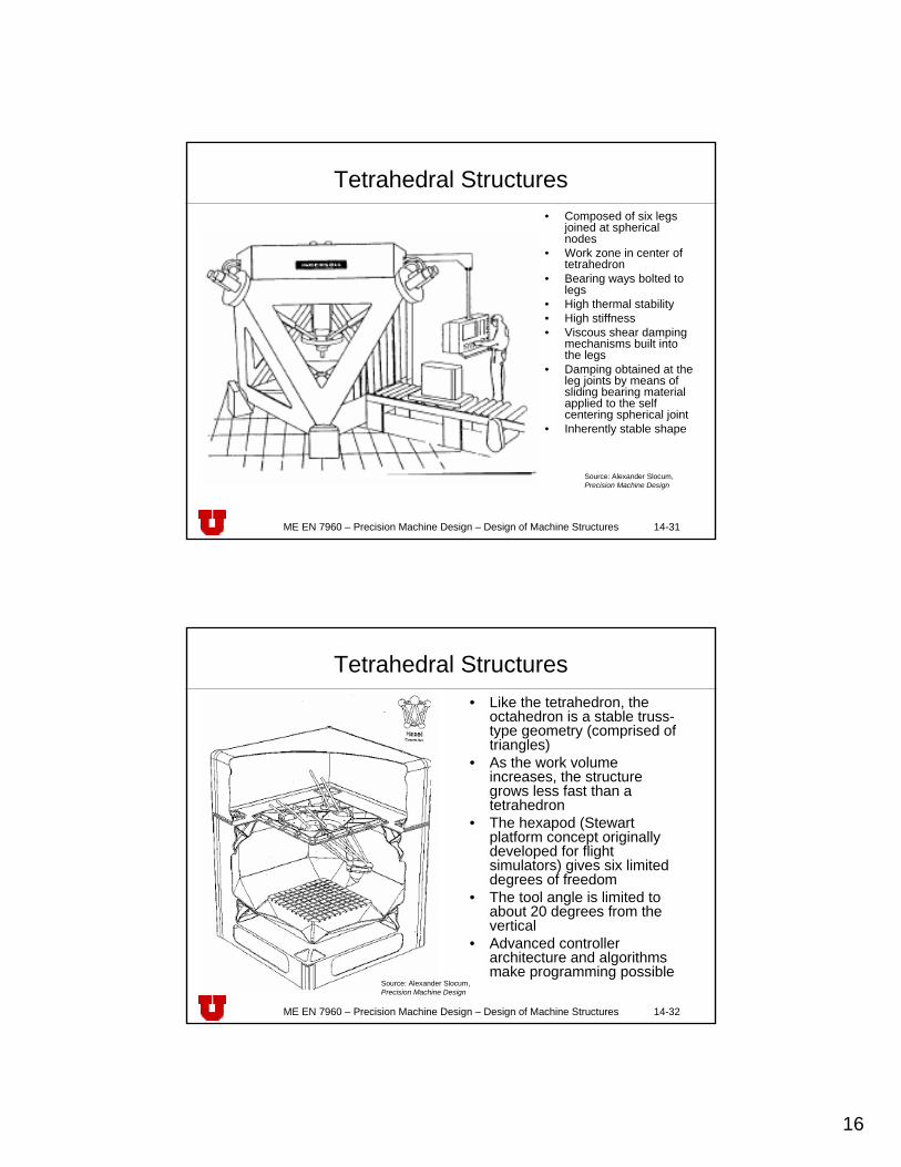
Closed Frame Structures• Moderately easy
access to work zone• Moderately strong
structural loop (like a micrometer!)
• Primary/follower actuator often required for the bridge
• Easier to obtain common centers of mass, stiffness, friction
Source: Alexander Slocum, Precision Machine Design
ME EN 7960 – Precision Machine Design – Design of Machine Structures 14-30
Closed Frame Structures
Source: Precision Design Lab
16
ME EN 7960 – Precision Machine Design – Design of Machine Structures 14-31
Tetrahedral Structures• Composed of six legs
joined at spherical nodes
• Work zone in center of tetrahedron
• Bearing ways bolted to legs
• High thermal stability• High stiffness• Viscous shear damping
mechanisms built into the legs
• Damping obtained at the leg joints by means of sliding bearing material applied to the self centering spherical joint
• Inherently stable shape
Source: Alexander Slocum, Precision Machine Design
ME EN 7960 – Precision Machine Design – Design of Machine Structures 14-32
Tetrahedral Structures• Like the tetrahedron, the
octahedron is a stable truss-type geometry (comprised of triangles)
• As the work volume increases, the structure grows less fast than a tetrahedron
• The hexapod (Stewart platform concept originally developed for flight simulators) gives six limited degrees of freedom
• The tool angle is limited to about 20 degrees from the vertical
• Advanced controller architecture and algorithms make programming possible
Source: Alexander Slocum, Precision Machine Design
17
ME EN 7960 – Precision Machine Design – Design of Machine Structures 14-33
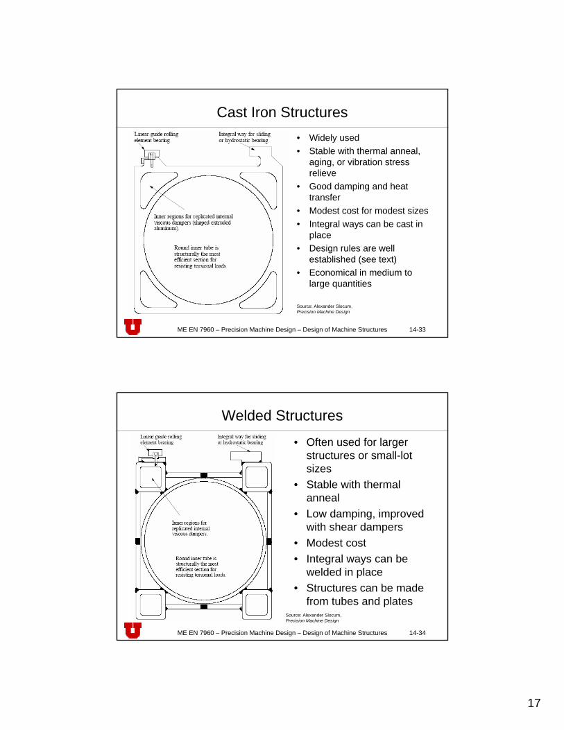
Cast Iron Structures• Widely used• Stable with thermal anneal,
aging, or vibration stress relieve
• Good damping and heat transfer
• Modest cost for modest sizes• Integral ways can be cast in
place• Design rules are well
established (see text)• Economical in medium to
large quantities
Source: Alexander Slocum, Precision Machine Design
ME EN 7960 – Precision Machine Design – Design of Machine Structures 14-34
Welded Structures
• Often used for larger structures or small-lot sizes
• Stable with thermal anneal
• Low damping, improved with shear dampers
• Modest cost• Integral ways can be
welded in place• Structures can be made
from tubes and platesSource: Alexander Slocum, Precision Machine Design

18
ME EN 7960 – Precision Machine Design – Design of Machine Structures 14-35
Epoxy Granite Structures
• Can be cast with intricate passages and inserts• Eepoxy granite/Ecast iron = 5/20• Exterior surface can be smooth and is ready to paint• Cast iron or steel weldments can be cast in place, but
beware of differential thermal expansion effects• Epoxy granite’s lower modulus, and use of foam cores
means that local plate modes require special care when designing inserts to which other structures are bolted
• Sliding contact bearing surfaces can be replicated onto the epoxy granite
ME EN 7960 – Precision Machine Design – Design of Machine Structures 14-36
Epoxy Granite Structures• Foam cores reduce weight:
• For some large one-of-a-kind machines• A mold is made from thin welded steel plate that remains an integral
part of the machine after the material is cast• Remember to use symmetry to avoid thermal warping• Consider the effects of differential thermal expansion when
designing the steel shell• The steel shell should be fully annealed after it is welded together
Source: Alexander Slocum, Precision Machine Design
19
ME EN 7960 – Precision Machine Design – Design of Machine Structures 14-37
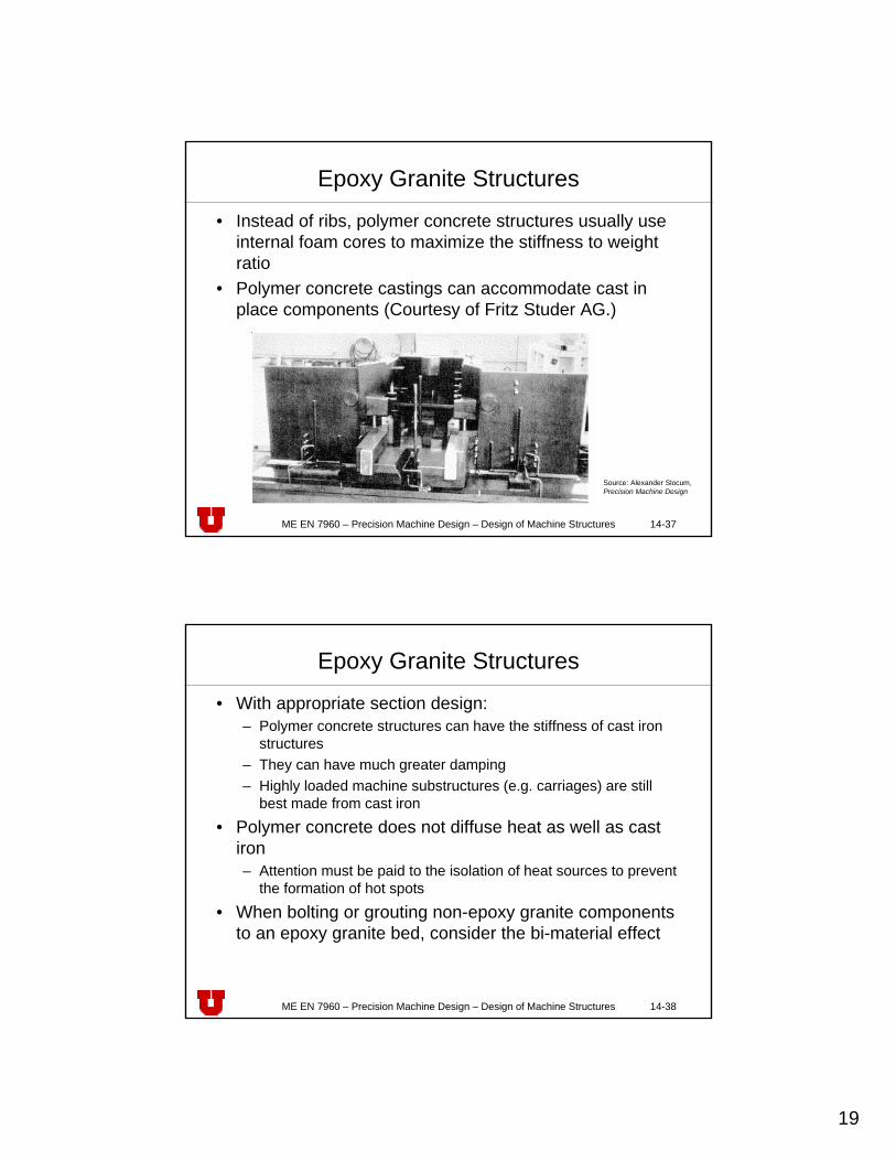
Epoxy Granite Structures
• Instead of ribs, polymer concrete structures usually use internal foam cores to maximize the stiffness to weight ratio
• Polymer concrete castings can accommodate cast in place components (Courtesy of Fritz Studer AG.)
Source: Alexander Slocum, Precision Machine Design
ME EN 7960 – Precision Machine Design – Design of Machine Structures 14-38
Epoxy Granite Structures
• With appropriate section design:– Polymer concrete structures can have the stiffness of cast iron
structures– They can have much greater damping– Highly loaded machine substructures (e.g. carriages) are still
best made from cast iron
• Polymer concrete does not diffuse heat as well as cast iron– Attention must be paid to the isolation of heat sources to prevent
the formation of hot spots
• When bolting or grouting non-epoxy granite components to an epoxy granite bed, consider the bi-material effect
20
ME EN 7960 – Precision Machine Design – Design of Machine Structures 14-39
Granite
• Dimensionally very stable• Must be sealed to avoid absorption of water• Can be obtained from a large number of vendors
providing excellent flatness and orthogonality• Cannot be tapped, therefore bolt holes consist of steel
plugs that have been potted in place that are drilled and tapped after the epoxy has cured
• Can chip• Provides excellent damping
ME EN 7960 – Precision Machine Design – Design of Machine Structures 14-40
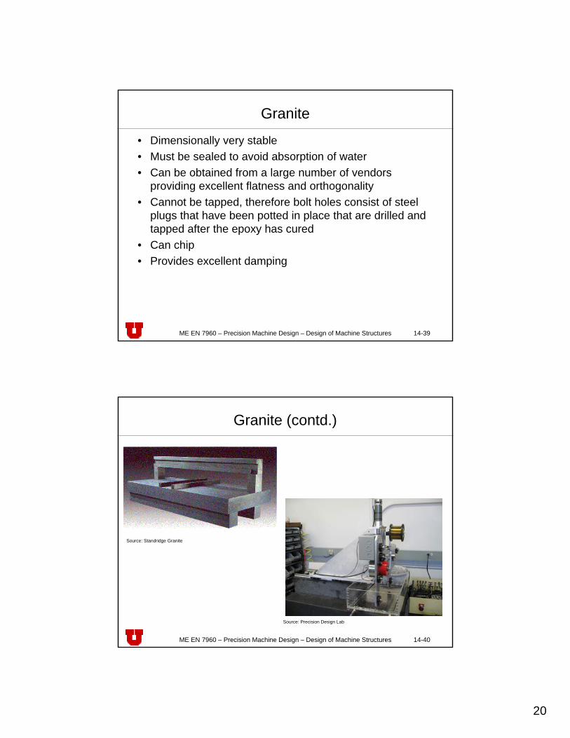
Granite (contd.)
Source: Standridge Granite
Source: Precision Design Lab

21
ME EN 7960 – Precision Machine Design – Design of Machine Structures 14-41
Constrained Layer DampingHow does it work?
• Visco-elastic layer damps motion between structure and constraining layer (from bending or torsion) by dissipating kinetic energy into heat
Top Constraining LayerA3, I3, E3
Bottom Constraining LayerA2, I2, E2
StructureA1, I1, E1
Viscoelastic DampingMaterial Gd, η
x
y
by2
y3
y1
L
ME EN 7960 – Precision Machine Design – Design of Machine Structures 14-42
Design parameters to tune damper
10
−= ∞
EIEIr
0 10 20 30 40 50 600.2
0.4
0.6
0.8
1
1.2
1.4
1.6
1.8Stiffness Ratio vs. Dynamic Compliance
Constrained Layer Wall Thickness [mm]
Com
plia
nce
Q*1
0, r
stiffness ratio r dynamic compliance Q*10
∑ ∞∞ −+=i
iii yyAEEIEI )( 220
x
y
by2
y3
y1

22
ME EN 7960 – Precision Machine Design – Design of Machine Structures 14-43
How is it implemented?
• For round structures, inner tube serves as constraining layer (ShearDamper™)
• Constraining layer is wrapped with damping material• Coated inner tube is inserted and gap filled with epoxy
ConstrainingLayer Ac, Ic
StructureAs, Is
Damping Material,Thickness td
ϕ
Epoxyyc
x
yRc
tc
ϕ
td
Ø DS,Thickness tS
Ø Dc,Thickness tc
ME EN 7960 – Precision Machine Design – Design of Machine Structures 14-44
ShearDamper™ - step by stepStep 1: split tube Step 2: wrap damping sheet around
Step 3: fill gap with epoxy Step 4: done
23
ME EN 7960 – Precision Machine Design – Design of Machine Structures 14-45
Any tradeoffs?
• Labor intensive – inner tube needs to be split• Inner tube and epoxy are expensive• Added weight lowers modal frequencies• Challenging if bottom is not accessible for sealing• Constraining layer performance depends on available
wall thickness• Only works for round or rectangular structures where a
matching split tube is available
ME EN 7960 – Precision Machine Design – Design of Machine Structures 14-46
How can we make it better?
• Replace steel tube AND epoxy with cheaper material that has better internal damping
• Make the need for splitting the constraining layer obsolete
• Make design more flexible in terms of shape and required stiffness
• Remove design constraints

24
ME EN 7960 – Precision Machine Design – Design of Machine Structures 14-47
But how?
• Four “sausage-like” damping sleeves are inserted between the outer structural and the inner support tube
• Dampers are filled with expanding concrete
Structure
As
, Is
Constraining
Layer Ac
, Ic
Damping Material
Thickness td
ϕ
Support Tube
AST
, IST
E. Bamberg, A.H. Slocum, “Concrete-based constrained layer damping”, Precision Engineering, 26(4), October 2002, pp. 430-441.
ME EN 7960 – Precision Machine Design – Design of Machine Structures 14-48
Concrete cast – it’s simple!
• Flexible constraining layer thickness – wide range of standard tubes can be used as support tube, wall thickness is no longer a design constraint
• Concrete provides additional damping• Cheap• Fast
25
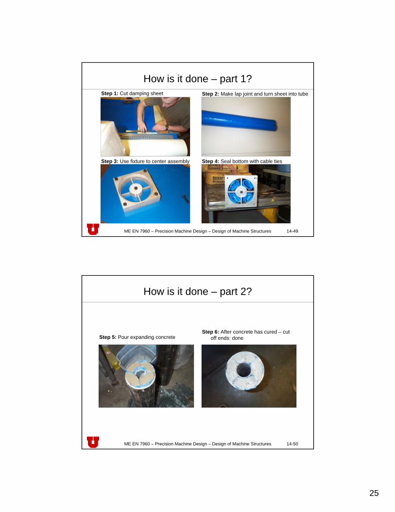
ME EN 7960 – Precision Machine Design – Design of Machine Structures 14-49
How is it done – part 1?Step 1: Cut damping sheet Step 2: Make lap joint and turn sheet into tube
Step 3: Use fixture to center assembly Step 4: Seal bottom with cable ties
ME EN 7960 – Precision Machine Design – Design of Machine Structures 14-50
How is it done – part 2?
Step 5: Pour expanding concreteStep 6: After concrete has cured – cut
off ends: done
26
ME EN 7960 – Precision Machine Design – Design of Machine Structures 14-51
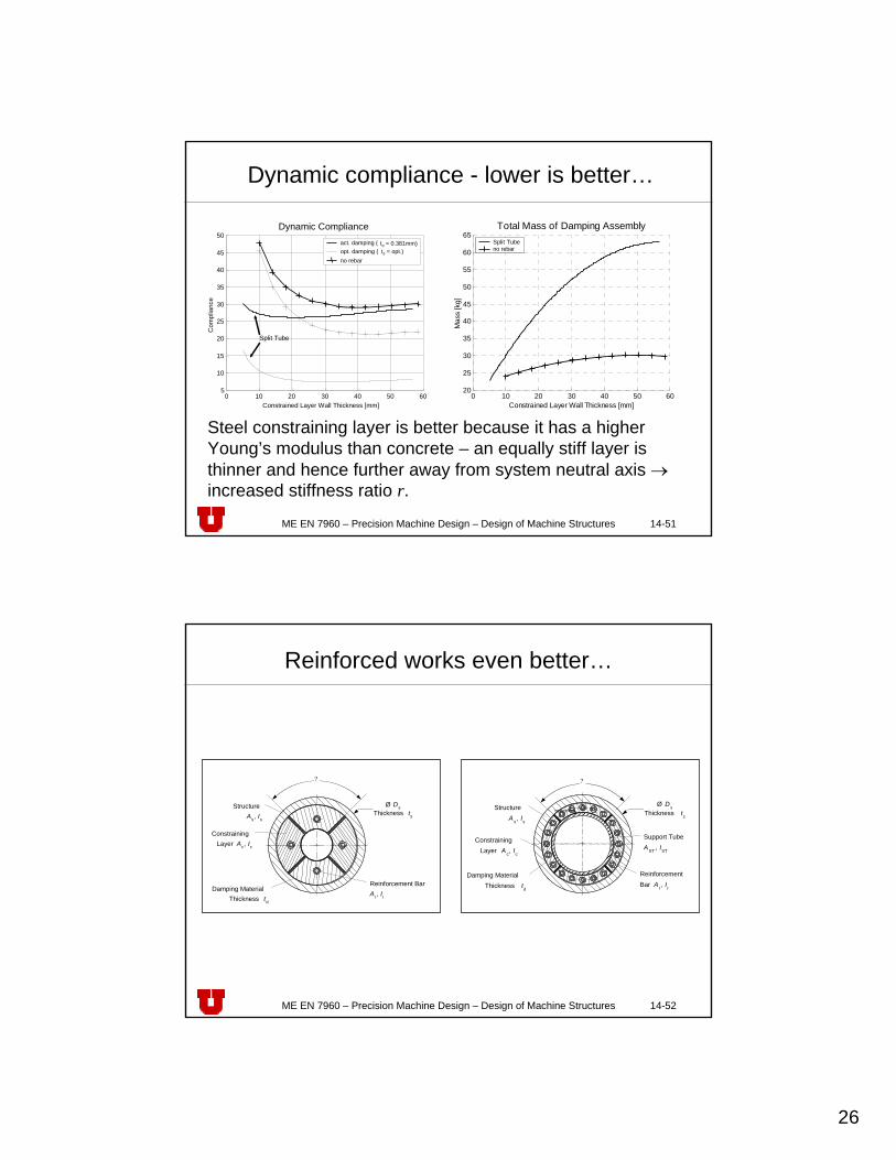
Dynamic compliance - lower is better…
0 10 20 30 40 50 6020
25
30
35
40
45
50
55
60
65Total Mass of Damping Assembly
Constrained Layer Wall Thickness [mm]
Mas
s [k
g]
Split Tubeno rebar
0 10 20 30 40 50 605
10
15
20
25
30
35
40
45
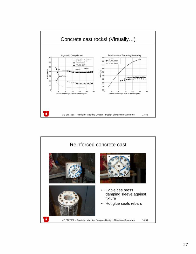
50Dynamic Compliance
Constrained Layer Wall Thickness [mm]
Com
plia
nce
Split Tube
act. damping ( td = 0.381mm)opt. damping ( td = opt.) no rebar
Steel constraining layer is better because it has a higher Young’s modulus than concrete – an equally stiff layer is thinner and hence further away from system neutral axis →increased stiffness ratio r.
ME EN 7960 – Precision Machine Design – Design of Machine Structures 14-52
Reinforced works even better…
StructureA s, Is
ConstrainingLayer A c, Ic
Damping MaterialThickness td
ReinforcementBar A r, Ir
Ø DsThickness ts
?
Support TubeAST , IST
StructureAs, Is
ConstrainingLayer Ac, Ic
Damping MaterialThickness td
Reinforcement BarAr, Ir
?
Ø DsThickness ts
27
ME EN 7960 – Precision Machine Design – Design of Machine Structures 14-53
Concrete cast rocks! (Virtually…)
0 10 20 30 40 50 6020
25
30
35
40
45
50
55
60
65Total Mass of Damping Assembly
Constrained Layer Wall Thickness [mm]
Mas
s [k
g]
Split Tube 0.5" rebar (3 pcs.) 0.75" rebar (2 pcs.)1.0" rebar (1 pcs.)
0 10 20 30 40 50 605
10
15
20
25
30
35
40Dynamic Compliance
Constrained Layer Wall Thickness [mm]
Com
plia
nce
Split Tube
act. damping ( td = 0.381mm)opt. damping ( td = opt.)
0.5" rebar (3 pcs.) 0.75" rebar (2 pcs.) 1.0" rebar (1 pcs.)
ME EN 7960 – Precision Machine Design – Design of Machine Structures 14-54
Reinforced concrete cast
• Cable ties press damping sleeve against fixture
• Hot glue seals rebars

28
ME EN 7960 – Precision Machine Design – Design of Machine Structures 14-55
Test setup
• HP 4-channel frequency analyzer• 3-axis accelerometer• 28 data points• Free-free setup
ME EN 7960 – Precision Machine Design – Design of Machine Structures 14-56
Response to impulse
-2 0 2 4 6 8 10
x 10-3
-0.3
-0.2
-0.1
0
0.1
0.2
0.3
0.4Concrete Filled Structure
Time [s]
-2 0 2 4 6 8 10
x 10-3
-0.2
-0.15
-0.1
-0.05
0
0.05
0.1
0.15
0.2Split Tube Damped Structure
Time [s]-2 0 2 4 6 8 10
x 10-3
-0.2
-0.15
-0.1
-0.05
0
0.05
0.1
0.15
0.2Concrete Cast Damped Structure
Time [s]-2 0 2 4 6 8 10
x 10-3
-0.2
-0.15
-0.1
-0.05
0
0.05
0.1
0.15
0.2Reinforced Concrete Cast Damped Structure
Time [s]
-2 0 2 4 6 8 10
x 10-3
-0.2
-0.15
-0.1
-0.05
0
0.05
0.1
0.15
0.2
0.25Sand Filled Structure
Time [s]-2 0 2 4 6 8 10
x 10-3
-0.25
-0.2
-0.15
-0.1
-0.05
0
0.05
0.1
0.15
0.2
0.25Undamped Structure
Time [s]
E. Bamberg, A.H. Slocum, “Concrete-based constrained layer damping”, Precision Engineering, 26(4), October 2002, pp. 430-441.
29
ME EN 7960 – Precision Machine Design – Design of Machine Structures 14-57
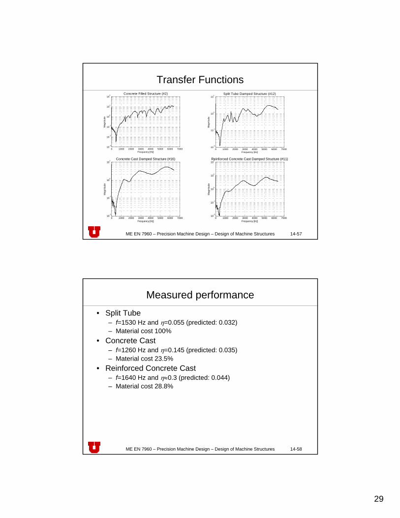
Transfer Functions
0 1000 2000 3000 4000 5000 6000 700010
-2
10-1
100
101 Concrete Cast Damped Structure (#16)
Frequency [Hz]
Mag
nitu
de
0 1000 2000 3000 4000 5000 6000 700010
-2
10-1
100
101
102Reinforced Concrete Cast Damped Structure (#11)
Frequency [Hz]
Mag
nitu
de
0 1000 2000 3000 4000 5000 6000 700010
-3
10-2
10-1
100
101
102
Concrete Filled Structure (#2)
Frequency [Hz]
Mag
nitu
de
0 1000 2000 3000 4000 5000 6000 700010
-2
10-1
100
101
Split Tube Damped Structure (#12)
Frequency [Hz]
Mag
nitu
de
ME EN 7960 – Precision Machine Design – Design of Machine Structures 14-58
Measured performance• Split Tube
– f=1530 Hz and η=0.055 (predicted: 0.032)– Material cost 100%
• Concrete Cast– f=1260 Hz and η=0.145 (predicted: 0.035)– Material cost 23.5%
• Reinforced Concrete Cast– f=1640 Hz and η≈0.3 (predicted: 0.044)– Material cost 28.8%