design of internal gear
TRANSCRIPT

4.7 Rack And Spur Gear
Table 4-6 presents the method for calculating the mesh of arack arid spur gear. Figure 4-9a shows the pitch circle of astandard gear and the pitch line of the rack. One rotation of the spur gear will displace the rack onecircumferential length of the gear's pitch circle, per the formula: ι = πmz (4-6)
Figure 4-9b shows a profile shifted spur gear, with positivecorrection xm, meshed with a rack. The spur gear has a largerpitch radius than standard, by the amount xm. Also, the pitchline of the rack has shifted outward by the amount xm. Table 4-6 presents the calculation of a meshed profileshifted spur gear and rack. If the correction factor x1, is 0,then it is the case of a standard gear meshed with the rack. The rack displacement, ι, is not changed in any way by theprofile shifting. Equation (4-6) remains applicable for anyamount of profile shift.
SECTION 5 INTERNAL GEARS
5.1 Internal Gear Calculations Calculation of a ProfileShifted Internal Gear
Figure 5-1 presents the mesh of aninternal gear and external gear. Ofvital importance is the operating(working) pitch diameters, dw, andoperating (working) pressure angle,αw They can be derived from centerdistance, ax, and Equations (5-1).
346
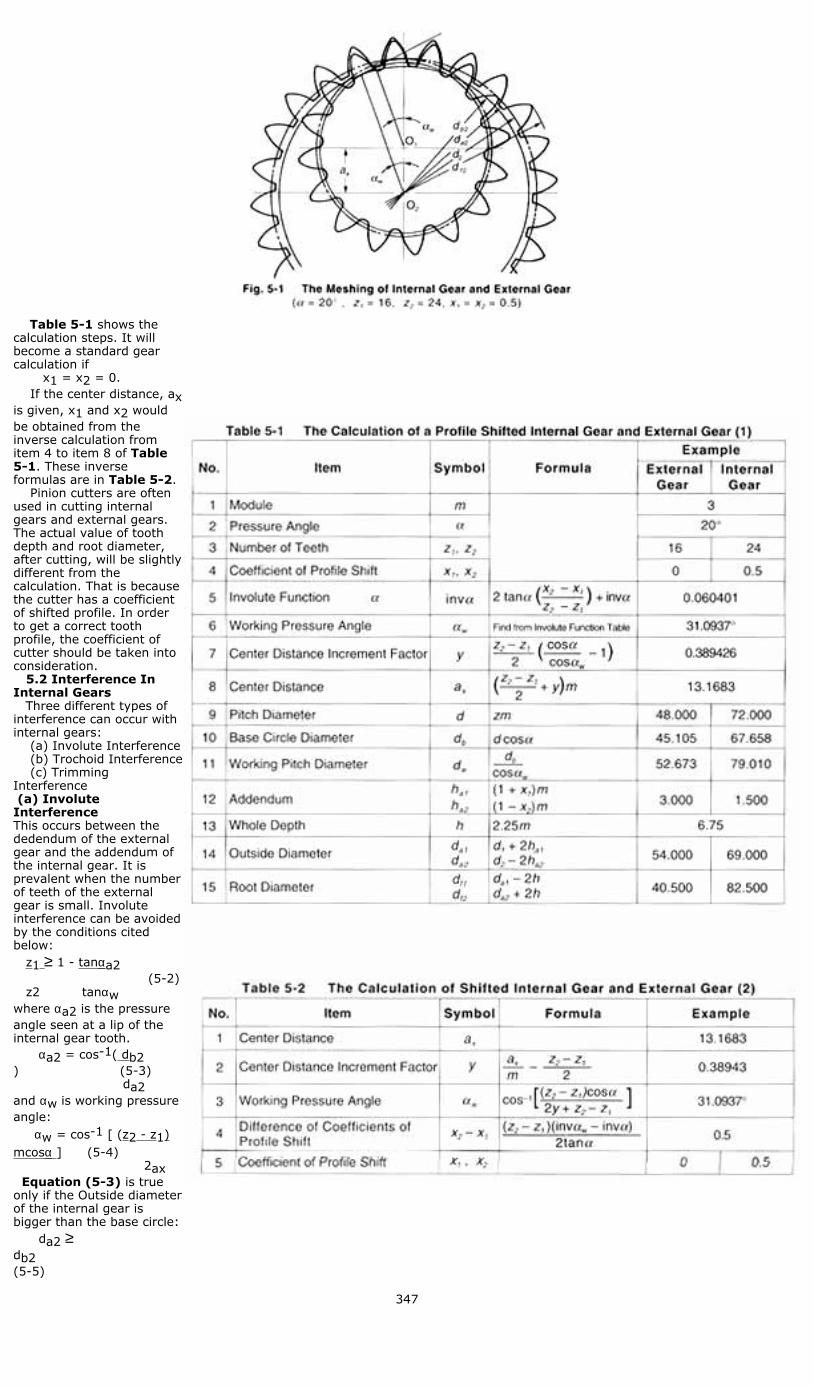
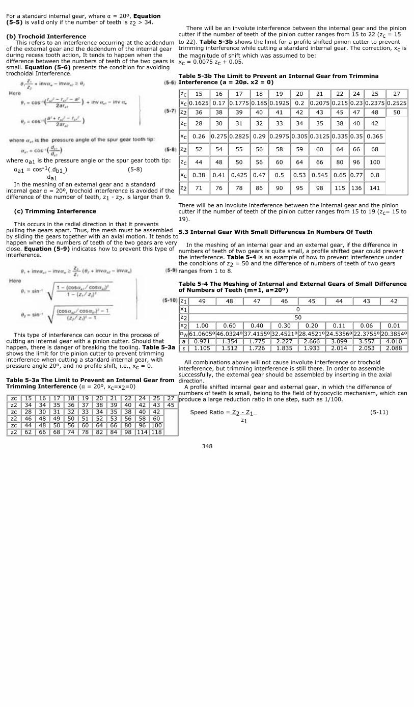
Table 5-1 shows thecalculation steps. It willbecome a standard gearcalculation if x1 = x2 = 0. If the center distance, axis given, x1 and x2 wouldbe obtained from theinverse calculation fromitem 4 to item 8 of Table5-1. These inverseformulas are in Table 5-2. Pinion cutters are oftenused in cutting internalgears and external gears.The actual value of toothdepth and root diameter,after cutting, will be slightlydifferent from thecalculation. That is becausethe cutter has a coefficientof shifted profile. In orderto get a correct toothprofile, the coefficient ofcutter should be taken intoconsideration. 5.2 Interference InInternal Gears Three different types ofinterference can occur withinternal gears: (a) Involute Interference (b) Trochoid Interference (c) TrimmingInterference (a) InvoluteInterferenceThis occurs between thededendum of the externalgear and the addendum ofthe internal gear. It isprevalent when the numberof teeth of the externalgear is small. Involuteinterference can be avoidedby the conditions citedbelow: z1 ≥ 1 - tanαa2 (5-2) z2 tanαw where αa2 is the pressureangle seen at a lip of theinternal gear tooth. αa2 = cos-1( db2) (5-3) da2 and αw is working pressureangle: αw = cos-1 [ (z2 - z1)mcosα ] (5-4) 2ax Equation (5-3) is trueonly if the Outside diameterof the internal gear isbigger than the base circle: da2 ≥db2 (5-5)
347
For a standard internal gear, where α = 20º, Equation(5-5) is valid only if the number of teeth is z2 > 34.
(b) Trochoid Interference This refers to an interference occurring at the addendumof the external gear and the dedendum of the internal gearduring recess tooth action, It tends to happen when thedifference between the numbers of teeth of the two gears issmall. Equation (5-6) presents the condition for avoidingtrochoidal Interference.
where αa1 is the pressure angle or the spur gear tooth tip:
αa1 = cos-1( db1 ) (5-8) da1 In the meshing of an external gear and a standardinternal gear α = 20º, trochoid interference is avoided if thedifference of the number of teeth, z1 - z2, is larger than 9.
(c) Trimming Interference
This occurs in the radial direction in that it preventspulling the gears apart. Thus, the mesh must be assembledby sliding the gears together with an axial motion. It tends tohappen when the numbers of teeth of the two gears are veryclose. Equation (5-9) indicates how to prevent this type ofinterference.
This type of interference can occur in the process ofcutting an internal gear with a pinion cutter. Should thathappen, there is danger of breaking the tooling. Table 5-3ashows the limit for the pinion cutter to prevent trimminginterference when cutting a standard internal gear, withpressure angle 20º, and no profile shift, i.e., xc = 0.
Table 5-3a The Limit to Prevent an Internal Gear fromTrimming Interference (α = 20º, xc=x2=0)
zc 15 16 17 18 19 20 21 22 24 25 27z2 34 34 35 36 37 38 39 40 42 43 45zc 28 30 31 32 33 34 35 38 40 42
z2 46 48 49 50 51 52 53 56 58 60zc 44 48 50 56 60 64 66 80 96 100z2 62 66 68 74 78 82 84 98 114 118
There will be an involute interference between the internal gear and the pinioncutter if the number of teeth of the pinion cutter ranges from 15 to 22 (zc = 15to 22). Table 5-3b shows the limit for a profile shifted pinion cutter to preventtrimming interference while cutting a standard internal gear. The correction, xc isthe magnitude of shift which was assumed to be:xc = 0.0075 zc + 0.05.
Table 5-3b The Limit to Prevent an Internal Gear from TrimminaInterference (a = 20ø. x2 = 0)
zc 15 16 17 18 19 20 21 22 24 25 27
xc 0.1625 0.17 0.1775 0.185 0.1925 0.2 0.2075 0.215 0.23 0.2375 0.2525
z2 36 38 39 40 41 42 43 45 47 48 50
zc 28 30 31 32 33 34 35 38 40 42
xc 0.26 0.275 0.2825 0.29 0.2975 0.305 0.3125 0.335 0.35 0.365
z2 52 54 55 56 58 59 60 64 66 68
zc 44 48 50 56 60 64 66 80 96 100
xc 0.38 0.41 0.425 0.47 0.5 0.53 0.545 0.65 0.77 0.8
z2 71 76 78 86 90 95 98 115 136 141
There will be an involute interference between the internal gear and the pinioncutter if the number of teeth of the pinion cutter ranges from 15 to 19 (zc= 15 to19).
5.3 Internal Gear With Small Differences In Numbers Of Teeth
In the meshing of an internal gear and an external gear, if the difference innumbers of teeth of two gears is quite small, a profile shifted gear could preventthe interference. Table 5-4 is an example of how to prevent interference underthe conditions of z2 = 50 and the difference of numbers of teeth of two gearsranges from 1 to 8.
Table 5-4 The Meshing of Internal and External Gears of Small Differenceof Numbers of Teeth (m=1, a=20º)
z1 49 48 47 46 45 44 43 42x1 0z2 50x2 1.00 0.60 0.40 0.30 0.20 0.11 0.06 0.01αw 61.0605º 46.0324º 37.4155º 32.4521º 28.4521º 24.5356º 22.3755º 20.3854ºa 0.971 1.354 1.775 2.227 2.666 3.099 3.557 4.010ε 1.105 1.512 1.726 1.835 1.933 2.014 2.053 2.088
All combinations above will not cause involute interference or trochoidinterference, but trimming interference is still there. In order to assemblesuccessfully, the external gear should be assembled by inserting in the axialdirection. A profile shifted internal gear and external gear, in which the difference ofnumbers of teeth is small, belong to the field of hypocyclic mechanism, which canproduce a large reduction ratio in one step, such as 1/100.
Speed Ratio = Z2 - Z1 (5-11) z1
348