design of interactive motor behaviors for close … · design of interactive motor behaviors for...
TRANSCRIPT

TECHNISCHE UNIVERSITAT MUNCHEN
Lehrstuhl fur Informationstechnische Regelung
Design of Interactive Motor Behaviors forClose Joint Action of Humans and Robots
Alexander Imanuel Mortl
Vollstandiger Abdruck der von der Fakultat fur Elektrotechnik und Informationstechnik
der Technischen Universitat Munchen zur Erlangung des akademischen Grades eines
Doktor-Ingenieurs (Dr.-Ing.)
genehmigten Dissertation.
Vorsitzender: Univ.-Prof. Gordon Cheng, Ph.D.
Prufer der Dissertation:
1. Univ.-Prof. Dr.-Ing. Sandra Hirche
2. Univ.-Prof. Dr.-Ing./Univ. Tokio Martin Buss
Die Dissertation wurde am 29.04.2014 bei der Technischen Universitat Munchen einge-
reicht und durch die Fakultat fur Elektrotechnik und Informationstechnik am 28.10.2014
angenommen.

Foreword
This thesis summarizes research carried out during my five years of work at the Institute
of Automatic Control Engineering (LSR) and later, at the newly founded Institute for
Information-Oriented Control (ITR) of the Technische Universitat Munchen. During this
time, a number of people gave me support and advice in different ways. As the thesis
at hand would not have been possible without their efforts, I would like to express my
gratitude to all these people.
First and foremost, I would like to thank my advisor Prof. Sandra Hirche for giving
me the opportunity to conduct research in her renowned robotics and control group, for
the stimulating discussions broadening my mind and scientific way of thinking, and for
providing me with enough freedom and an excellent research environment to realize my
ideas. Sincere thanks also go to Prof. Martin Buss for leading the LSR as an institute that
fosters a collaborative and interdisciplinary spirit. I thank the administrative team of the
institutes for their kind and professional support in all nonscientific matters.
My collaborators within the excellence initiative research cluster CoTeSys considerably
contributed to the successful conclusion of this thesis. Special thanks go to my long-time
office mate Martin Lawitzky; thank you for the fruitful collaborations and discussions we
had in the field of physical human-robot interaction, for your kind advice in all coding
and computing issues, and the funny moments we shared. In related pHRI projects, I
was working with Philine Donner and Jose Ramon Medina Hernandez; thank you for your
enthusiasm and inspiration during our joyful collaborations. The interdisciplinary collab-
oration with Prof. Cagatay Basdogan, Dr. Metin Sezgin and Dr. Ayse Kucukyılmaz from
Koc University, Istanbul, was an exciting experience during my PhD times. I especially
thank Ayse for her scientific input and commitment during her stay at the lab in Munich,
which enabled the profound study on role allocation. In the field of movement coordination,
I was working with Tamara Lorenz among other researchers at the Ludwigs-Maximilians-
Universitat Munchen; thank you for the pleasant collaborations we had for all these years.
I thank Dr. Azwirman Gusrialdi for the inspiring discussions on synchronization theory.
My gratitude also goes to the former MuRoLa team and all my colleagues at the LSR and
the ITR for the helpfulness and the pleasant atmosphere in the lab.
Also, I would like to thank all the students who worked closely with me, especially Huan
Lu for her contribution to the manipulator control scheme, as well as Marco Karmann, Lars
Kreutz and Lu Zeng for their valuable support in conducting the numerous experiments.
Finally, I would like to express my gratitude to my parents and my girlfriend Julia for
accompanying me with their enduring encouragement, their understanding and love during
this challenging period of my live.
Munich, April 2014 Alexander Mortl
iii

Abstract
Advanced behavioral capabilities are key to the successful application of robotic assistants
and companions in human environments. Possible scenarios range from activities of daily
living, such as household chores, over assembly in highly flexible manufacturing settings,
physical training for rehabilitation to cooperation in search and rescue teams. Since many
of those applications involve close joint action with humans and shared workspaces, robots
need to be capable of human-oriented and socially compatible motor behaviors. The ulti-
mate goal shall be seamless interaction; if a human partner in a joint action task is replaced
by a robot, the interaction shall not deteriorate, neither in terms of human sensation nor
in terms of task performance. Close couplings of the partners make the design of interac-
tive motor behavior a challenging endeavor. In particular, joint action mediated through
the visual and the haptic modality induces instantaneous negotiation processes between
the partners: Fluent and collision-free interaction in shared workspaces requires intuitive
strategies for movement coordination; the energy exchange through physical cooperation
poses the additional challenge of efficient effort distribution. Only a deep understanding
of the human interactive behavior can lead to seamless interaction with robots. Experi-
mental studies of human joint action and system-theoretic models need to be co-designed
to obtain valuable models of human behavior. Prototyping and systematic evaluations by
means of immersive scenarios and realistic embodiments of robotic partners are technically
challenging, yet essential steps towards successful human-robot joint action.
This thesis presents a novel interdisciplinary methodology, in order to achieve a holistic
design of interactive motor behaviors for robots. Two design perspectives are identified
and pursued. The analytical perspective aims at the model-directed exploration of human
behavior through the experimental study of how humans interact. In the context of visual
coordination, this perspective is shown to provide a superior entry into the design process.
A quantitative description of inter-human movement coordination in the form of a fully
parameterized, dynamical synchronization model is developed. The synthetical perspec-
tive aims at a system-theoretic and function-oriented design of interactive behavior, while
existing principles and models of human behavior are integrated as well. Utilizing the
identified model of human coordination behavior and dynamical system theory, synchro-
nization behavior for goal-directed joint action is synthesized. Simultaneous phase and
event synchronization allows to dynamically form a variety of interaction patterns, which
enable a robot to smoothly coordinate its movements with those of a human partner. In
the context of visual-haptic cooperation, role behavior is designed, in order to dynamically
distribute the physical effort during joint object manipulation. Based on the geometrical
decomposition of the task, effort sharing policies are developed and efficient strategies for
dynamic role allocation are synthesized. As the methodology emphasizes a tight interre-
lation of theory and experimentation, prototyping of interactive behavior and extensive
experimental studies by means of an anthropomorphic robot and a virtual reality system
are conducted throughout this work.
v
Zusammenfassung
Hochentwickelte Verhaltensweisen sind entscheidend fur den erfolgreichen Einsatz von Ro-
botern als Helfer und Begleiter im Umfeld des Menschen. Mogliche Szenarien reichen von
Alltagstatigkeiten wie Hausarbeiten, uber Montage in der hochflexiblen Fertigung, physi-
schem Training in der Rehabilitation bis hin zu Kooperation in Such- und Rettungsteams.
Da viele dieser Anwendungen enge Zusammenarbeit mit Menschen und gemeinsame Ar-
beitsraume bedingen, mussen Roboter motorisches Verhalten beherrschen, das am Men-
schen orientiert und sozial kompatibel ist. Oberstes Ziel soll eine reibungslose Interaktion
sein; wenn ein menschlicher Partner in einer gemeinsamen Tatigkeit durch einen Roboter
ersetzt wird, darf sich die Interaktion bezogen auf die menschliche Wahrnehmung und die
Arbeitsleistung nicht verschlechtern. Enge Verkopplungen der Partner machen die Ent-
wicklung von motorischem Interaktionsverhalten zu einer Herausforderung. Visuell und
haptisch vermitteltes, gemeinsames Handeln bedingt insbesondere Prozesse des unmittel-
baren Verhandelns zwischen den Partnern: Flussige und kollisionsfreie Interaktion in ge-
meinsamen Arbeitsraumen erfordert intuitive Strategien zur Bewegungskoordination; der
Energieaustausch durch physische Kooperation bildet die zusatzliche Herausforderung, den
Arbeitsaufwand effizient zu verteilen. Einzig ein tiefgreifendes Verstandnis des menschli-
chen Interaktionsverhaltens kann zu einer reibungslosen Interaktion mit Robotern fuhren.
Experimentalstudien der menschlichen Zusammenarbeit und systemtheoretische Modelle
sind gemeinsam zu entwickeln, um hochwertige Verhaltensmodelle des Menschen zu ge-
winnen. Prototypenentwicklung und methodische Evaluierung mittels immersiver Szenari-
en und realistischer Verkorperungen von Robotern sind technisch herausfordernde, jedoch
unerlassliche Schritte in Richtung erfolgreicher Mensch-Roboter Zusammenarbeit.
Diese Dissertation stellt eine neue interdisziplinare Methodik vor, um motorisches In-
teraktionsverhalten fur Roboter ganzheitlich zu entwickeln. Zwei Entwurfsperspektiven
werden identifiziert und verfolgt. Die analytische Perspektive strebt eine modellorientier-
te Erforschung menschlichen Verhaltens an, indem die Interaktion von Menschen experi-
mentell untersucht wird. Im Rahmen der visuellen Koordination wird gezeigt, dass diese
Perspektive einen ausgezeichneten Einstieg in den Entwurfsprozess darstellt. Es wird ei-
ne quantitative Beschreibung der zwischenmenschlichen Bewegungskoordination in Form
eines parametrierten, dynamischen Synchronisierungsmodells entwickelt. Die synthetische
Perspektive strebt ein systemtheoretisches und funktionsorientiertes Design an, wahrend
bestehende Grundsatze und Modelle menschlichen Verhaltens einbezogen werden. Das Mo-
dell des menschlichen Koordinationsverhaltens und dynamische Systemtheorie wird ange-
wendet, um Synchronisierungsverhalten fur zielgerichtetes, gemeinsames Handeln zu syn-
thetisieren. Durch gleichzeitige Phasen- und Ereignissynchronisierung kann dynamisch eine
Vielzahl von Interaktionsmustern gebildet werden, welche es einem Roboter ermoglichen,
seine Bewegungen reibungslos mit denen eines Menschen abzustimmen. Im Rahmen der
visuell-haptischen Kooperation werden Rollenverhalten entwickelt, um den physischen Auf-
wand wahrend der gemeinsamen Objekthandhabung dynamisch zu verteilen. Anhand einer
geometrischen Aufgabenzerlegung werden Methoden zur Aufwandsaufteilung entwickelt
und effiziente Strategien zur dynamischen Rollenverteilung synthetisiert. Da die Methodik
eine enge Beziehung von Theorie und Experiment betont, werden in der gesamten Arbeit
prototypische Interaktionsverhalten entwickelt und umfassende Experimentalstudien mit
einem anthropomorphen Roboter und einem System fur virtuelle Realitat durchgefuhrt.
vi
Contents
1 Introduction 1
1.1 Applications . . . . . . . . . . . . . . . . . . . . . . . . . . . . . . . . . . . 2
1.2 Problem Definition . . . . . . . . . . . . . . . . . . . . . . . . . . . . . . . 3
1.3 Challenges . . . . . . . . . . . . . . . . . . . . . . . . . . . . . . . . . . . . 4
1.4 Main Contributions and Outline . . . . . . . . . . . . . . . . . . . . . . . . 5
2 Conceptual Foundations 9
2.1 Design Methodology . . . . . . . . . . . . . . . . . . . . . . . . . . . . . . 9
2.1.1 Requirements on Interactive Motor Behavior . . . . . . . . . . . . . 10
2.1.2 Two Design Perspectives . . . . . . . . . . . . . . . . . . . . . . . . 11
2.2 System-Theoretic Foundations . . . . . . . . . . . . . . . . . . . . . . . . . 14
2.2.1 Dynamical Systems . . . . . . . . . . . . . . . . . . . . . . . . . . . 14
2.2.2 Behavioral Dynamics . . . . . . . . . . . . . . . . . . . . . . . . . . 15
2.2.3 System Identification . . . . . . . . . . . . . . . . . . . . . . . . . . 17
2.3 Studying Human Interactive Behavior . . . . . . . . . . . . . . . . . . . . . 18
2.3.1 Aspects of Psychological Experiments . . . . . . . . . . . . . . . . . 19
2.3.2 Experimental Measures . . . . . . . . . . . . . . . . . . . . . . . . . 21
2.4 Technical Foundations . . . . . . . . . . . . . . . . . . . . . . . . . . . . . 24
2.4.1 Manipulator Control . . . . . . . . . . . . . . . . . . . . . . . . . . 24
2.4.2 Control of Mobile Manipulators . . . . . . . . . . . . . . . . . . . . 26
2.5 Summary . . . . . . . . . . . . . . . . . . . . . . . . . . . . . . . . . . . . 28
3 Modeling of Human Movement Coordination 29
3.1 Background . . . . . . . . . . . . . . . . . . . . . . . . . . . . . . . . . . . 30
3.1.1 Experimental Studies and Key Results . . . . . . . . . . . . . . . . 30
3.1.2 Modeling and Identification Approaches . . . . . . . . . . . . . . . 31
3.2 Model-Directed Experimental Design . . . . . . . . . . . . . . . . . . . . . 34
3.2.1 Concept and Paradigm . . . . . . . . . . . . . . . . . . . . . . . . . 34
3.2.2 Human-Human Experiment . . . . . . . . . . . . . . . . . . . . . . 37
3.2.3 Phase Reconstruction Techniques . . . . . . . . . . . . . . . . . . . 40
3.3 Analytical Results . . . . . . . . . . . . . . . . . . . . . . . . . . . . . . . . 42
3.3.1 Synchronization Patterns . . . . . . . . . . . . . . . . . . . . . . . . 42
3.3.2 Observing the Response to Initial Excitation . . . . . . . . . . . . . 44
3.3.3 Attractor Regimes . . . . . . . . . . . . . . . . . . . . . . . . . . . 45
3.3.4 Synchronization Index . . . . . . . . . . . . . . . . . . . . . . . . . 47
3.4 Human-Human Synchronization Model . . . . . . . . . . . . . . . . . . . . 48
3.4.1 Model Structure . . . . . . . . . . . . . . . . . . . . . . . . . . . . . 48
3.4.2 Stability Analysis . . . . . . . . . . . . . . . . . . . . . . . . . . . . 50
vii

Contents
3.4.3 Identification and Results . . . . . . . . . . . . . . . . . . . . . . . 52
3.5 Discussion . . . . . . . . . . . . . . . . . . . . . . . . . . . . . . . . . . . . 55
3.5.1 Interpretation of Results . . . . . . . . . . . . . . . . . . . . . . . . 55
3.5.2 Implications for the Design of Interactive Behavior . . . . . . . . . 57
3.6 Conclusion and Open Issues . . . . . . . . . . . . . . . . . . . . . . . . . . 58
4 Synchronization Behavior for Action Coordination 61
4.1 Background . . . . . . . . . . . . . . . . . . . . . . . . . . . . . . . . . . . 62
4.1.1 Human Sensorimotor Synchronization . . . . . . . . . . . . . . . . . 62
4.1.2 Limit Cycle Systems in Robotics . . . . . . . . . . . . . . . . . . . 63
4.1.3 Human-Machine Movement Synchronization . . . . . . . . . . . . . 63
4.2 Design of Synchronization Behavior . . . . . . . . . . . . . . . . . . . . . . 64
4.2.1 Representation of Repetitive Joint Action . . . . . . . . . . . . . . 64
4.2.2 Synchronization Modes . . . . . . . . . . . . . . . . . . . . . . . . . 68
4.2.3 Dynamical Entrainment Process . . . . . . . . . . . . . . . . . . . . 70
4.2.4 From Movement to Phase . . . . . . . . . . . . . . . . . . . . . . . 74
4.2.5 From Phase to Movement . . . . . . . . . . . . . . . . . . . . . . . 77
4.3 Human-Robot Movement Synchronization . . . . . . . . . . . . . . . . . . 80
4.3.1 The Joint Action Task . . . . . . . . . . . . . . . . . . . . . . . . . 80
4.3.2 Implementation . . . . . . . . . . . . . . . . . . . . . . . . . . . . . 81
4.3.3 Human-Robot Experiment . . . . . . . . . . . . . . . . . . . . . . . 85
4.3.4 Evaluation Criteria . . . . . . . . . . . . . . . . . . . . . . . . . . . 87
4.4 Experimental Results . . . . . . . . . . . . . . . . . . . . . . . . . . . . . . 88
4.4.1 External Assessment of Synchronization . . . . . . . . . . . . . . . 89
4.4.2 Internal Assessment of the Behavioral Dynamics . . . . . . . . . . . 90
4.5 Discussion . . . . . . . . . . . . . . . . . . . . . . . . . . . . . . . . . . . . 92
4.5.1 Implications on Human-Robot Joint Action . . . . . . . . . . . . . 92
4.5.2 Issues in the Design of Synchronization Behavior . . . . . . . . . . . 93
4.6 Conclusion and Open Issues . . . . . . . . . . . . . . . . . . . . . . . . . . 94
5 Role Behavior for Physical Cooperation 99
5.1 Background . . . . . . . . . . . . . . . . . . . . . . . . . . . . . . . . . . . 100
5.1.1 Physical Robotic Assistance . . . . . . . . . . . . . . . . . . . . . . 100
5.1.2 Relation to Haptic Shared Control . . . . . . . . . . . . . . . . . . 103
5.2 Physical Effort Sharing in Cooperative Manipulation . . . . . . . . . . . . 104
5.2.1 Problem Formulation and Concept . . . . . . . . . . . . . . . . . . 104
5.2.2 Task Representation . . . . . . . . . . . . . . . . . . . . . . . . . . 106
5.2.3 Input Wrench Decomposition . . . . . . . . . . . . . . . . . . . . . 108
5.2.4 Effort Sharing Policies . . . . . . . . . . . . . . . . . . . . . . . . . 110
5.3 Static Role Behavior . . . . . . . . . . . . . . . . . . . . . . . . . . . . . . 114
5.3.1 Interaction Control Scheme . . . . . . . . . . . . . . . . . . . . . . 114
5.3.2 Analysis of the Interactive Behavior . . . . . . . . . . . . . . . . . . 116
5.3.3 Experimental Evaluation . . . . . . . . . . . . . . . . . . . . . . . . 119
5.4 Design of Dynamic Role Behavior . . . . . . . . . . . . . . . . . . . . . . . 122
5.4.1 Role Allocation Strategies . . . . . . . . . . . . . . . . . . . . . . . 122
viii
Contents
5.4.2 Synthesis of Role Allocations . . . . . . . . . . . . . . . . . . . . . 127
5.4.3 Interaction Control Scheme . . . . . . . . . . . . . . . . . . . . . . 130
5.5 Evaluation of Dynamic Role Behavior . . . . . . . . . . . . . . . . . . . . . 131
5.5.1 Human-Robot Experiment . . . . . . . . . . . . . . . . . . . . . . . 132
5.5.2 Evaluation Criteria . . . . . . . . . . . . . . . . . . . . . . . . . . . 135
5.5.3 Experimental Results . . . . . . . . . . . . . . . . . . . . . . . . . . 137
5.5.4 Discussion . . . . . . . . . . . . . . . . . . . . . . . . . . . . . . . . 140
5.6 Conclusion and Open Issues . . . . . . . . . . . . . . . . . . . . . . . . . . 142
6 Conclusions and Future Directions 145
6.1 Concluding Remarks . . . . . . . . . . . . . . . . . . . . . . . . . . . . . . 145
6.2 Outlook . . . . . . . . . . . . . . . . . . . . . . . . . . . . . . . . . . . . . 147
A Experimental Setups 149
A.1 VR-System for Visual-Haptic Rendering . . . . . . . . . . . . . . . . . . . 149
A.2 Environment for Full-Scale Interaction . . . . . . . . . . . . . . . . . . . . 150
A.2.1 Six DoF Mobile Manipulator . . . . . . . . . . . . . . . . . . . . . . 150
A.2.2 Motion Capture Systems . . . . . . . . . . . . . . . . . . . . . . . . 151
B Haptic Rendering of VR Scenes 152
B.1 Haptic Interfaces . . . . . . . . . . . . . . . . . . . . . . . . . . . . . . . . 152
B.2 Haptic Rendering with Admittance-Type Devices . . . . . . . . . . . . . . 152
B.3 Visual Rendering of Virtual Environments . . . . . . . . . . . . . . . . . . 154
C Questionnaire 155
C.1 Task Load . . . . . . . . . . . . . . . . . . . . . . . . . . . . . . . . . . . . 155
C.2 Task Experience . . . . . . . . . . . . . . . . . . . . . . . . . . . . . . . . . 155
Bibliography 157
ix

List of Figures
1.1 Exemplary scenario of close joint action: Cooperative assembly during car
restoration. . . . . . . . . . . . . . . . . . . . . . . . . . . . . . . . . . . . 2
1.2 Investigated classes of joint motor action: Visual coordination with individ-
ual goals (left) and visual-haptic cooperation towards a shared goal (right). 3
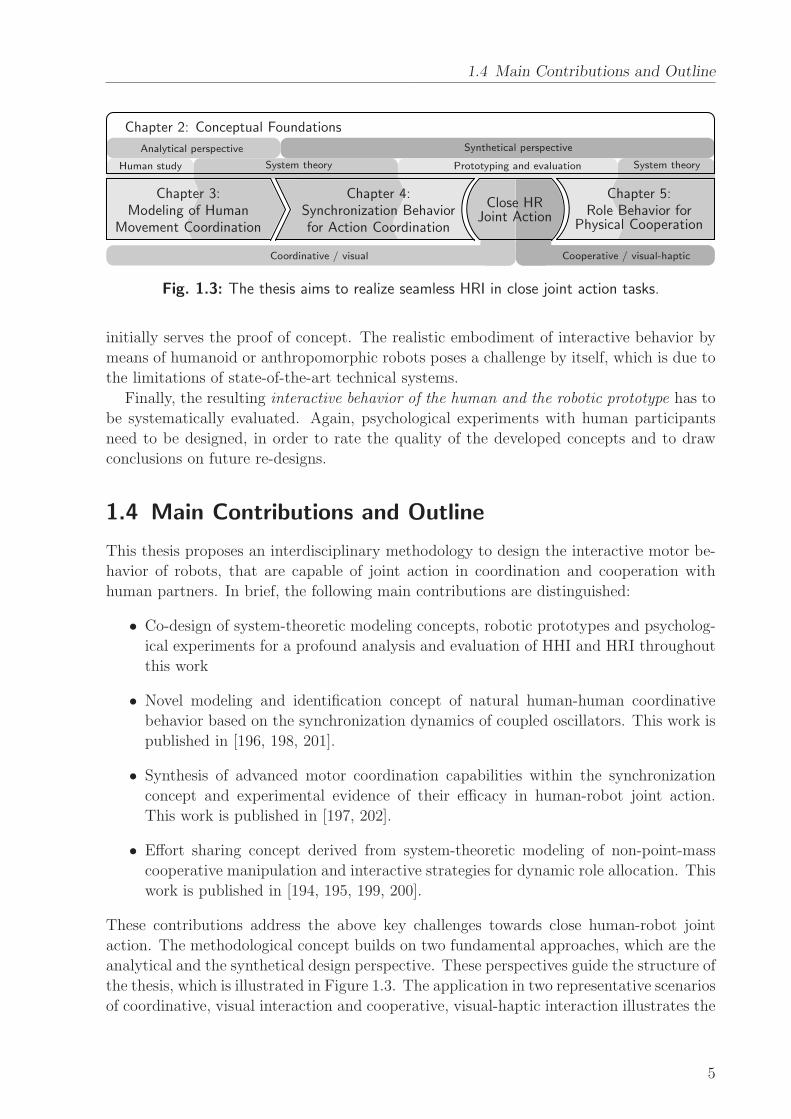
1.3 The thesis aims to realize seamless HRI in close joint action tasks. . . . . . 5
2.1 Dynamical formulation of the perception-action cycle between an agent
and the environment, and the concept of behavioral dynamics. Adapted
from Warren [185]. . . . . . . . . . . . . . . . . . . . . . . . . . . . . . . . 15
2.2 Inertial admittance-type control scheme including manipulator-base coordi-
nation. . . . . . . . . . . . . . . . . . . . . . . . . . . . . . . . . . . . . . . 26
2.3 (a) Desired and (b) actual configuration of the base with respect to the
rigidly grasped object, described by the preferred and actual configuration
of the end effector, x∗Rd and xR respectively. . . . . . . . . . . . . . . . . . 27
3.1 Overview scheme depicting the two-layered concept of movement coordi-
nation. Agent a and b jointly engage in repetitive actions. The observed
movements are transformed to phases in the lower layer. In the upper layer,
the coordination behavior is assumed to be governed by the individual and
joint behavioral dynamics, which are represented by coupled phase oscilla-
tors. Dark arrows represent the analytical perspective on HHI pursued in
this chapter. Light arrows outline the envisaged stage of action generation
when the behavioral model is deployed to HRI, see Chapter 4. . . . . . . . 35
3.2 Experimental task designed to study HHI behavior. Participants are per-
forming goal-directed arm movements while sitting face to face. . . . . . . 36
3.3 Experimental setup with dimensions. Person a and person b sit in chairs
opposite to each other. The task was to alternately tap on two assigned
dots (start and target, diameter 8mm) with a pen in hand. The dots were
marked on a round table and each one was surrounded by a white area
(diameter 60mm). . . . . . . . . . . . . . . . . . . . . . . . . . . . . . . . 38
3.4 Motion trajectory x(t) ∈ R3 and projected trajectory x(t) ∈ R between the
agent’s start and target point. The origin O of the task space is set such,
that x(t) is zero-mean. . . . . . . . . . . . . . . . . . . . . . . . . . . . . . 40
3.5 State-space trajectory of quasi-harmonic human hand movements. Nor-
malized velocity is plotted against the normalized position. The counter-
clockwise evolving trajectories form approximately a closed curve of circular
shape. The position xn is reversed to obtain a phase θ increasing over time. 41
xi
List of Figures
3.6 How did synchrony evolve? Visualization of synchronization as Lissajous
plots of the hand position of person b relative to that of person a, accu-
mulated in a heat map. Data are plotted separately for the conditions
zero-cycle (ZC), quarter-cycle (QC) and half-cycle (HC) as well as for the
first, third, sixth and ninth cycle. The dyads tend to synchronize already
early in the trial. . . . . . . . . . . . . . . . . . . . . . . . . . . . . . . . . 43
3.7 Actual initial phase differences Φ0 = Φ(t = 0) over all trials for the con-
ditions zero-cycle (ZC), quarter-cycle (QC) and half-cycle (HC), calculated
with the spectral technique. Time t = 0 denotes the movement onset of the
delayed person. Dashed lines indicate the phase relations triggered by the
start off conditions. . . . . . . . . . . . . . . . . . . . . . . . . . . . . . . . 44
3.8 Histograms of the relative phase difference Φr (a)-(c), and heat maps depict-
ing the transients of Φr towards the respective attractor Φr (ordinate) (d)-(f),
accumulating all trials in the three conditions. Brightness codes frequency.
The plot is indexed by the phase θi of the delayed person (abscissa). Phases
are obtained from the spectral technique. . . . . . . . . . . . . . . . . . . . 45
3.9 Synchronization index SI for the conditions zero-cycle (ZC), quarter-cycle
(QC) and half-cycle (HC), averaged over all trials. For comparison, the SI
is calculated separately for the state-space, spectral and hybrid technique.
The bars represent standard errors of the means. . . . . . . . . . . . . . . . 47
3.10 Stability of the equilibrium points of the extended Kuramoto model. The
phase difference between the two oscillators converges close to 0 (in-phase)
or π (anti-phase) depending on the strength of couplingK and the frequency
detuning ∆ω. . . . . . . . . . . . . . . . . . . . . . . . . . . . . . . . . . . 51
3.11 Phase difference Φ(t) derived from experimental data via the spectral tech-
nique and simulated by means of the parameterized model. The parame-
ters [rad·s−1] are ∆ω=-0.49 and K=0.41 at an RMSEΦ=0.23. . . . . . . . 53
4.1 Limit cycle γ of an exemplary cyclic state trajectory ξ(t) in its state space
with n = 3. If γ is cyclic, yet not closed exactly, the period T is determined
by the return time of ξ to the Poincare secant surface S. . . . . . . . . . . 65
4.2 (a) Exemplary limit cycle γ with the state ξ = [x x ]T and L = 3 prim-
itives. The segmentation points ξi are given by the intersection of γ with
the abscissa. (b) The corresponding events tl,1, primitive durations Tl,1 and
the uniformly growing phase θ depicted for period i = 1. . . . . . . . . . . 66
4.3 Modes between harmonic oscillations: Phase synchronization resulting in
in-phase or anti-phase relations comes about with event synchronization
with respect to the segmentation points ξa/b1 and ξ
a/b2 . (a) Motion tra-
jectories xa/b(t) illustrating the temporal relation. (b) Their limit cycle
representations γa/b in a position-velocity state space, illustrating the phase
difference. . . . . . . . . . . . . . . . . . . . . . . . . . . . . . . . . . . . . 69
xii
List of Figures
4.4 (a) Exemplary limit cycles γa/b with La = 2 and Lb = 3 primitives in
position-velocity state spaces. The evolution of the events in γa/b, (b) with-
out synchronization, (c) for synchronization of the events (ta0, tb0) as achieved
by phase synchronization, (d) for additional synchronization of (ta1, tb2). The
shaded areas indicate the time span ∆t defining event synchronization. . . 70
4.5 R.h.s. terms of an exemplary phase difference dynamics (4.12) over Φ ∈[0, 2π]. The intersection points of the graphs of ∆ω and −H(Φ) denote the
equilibria with Φ = 0. The vector field is illustrated on the abscissa. . . . . 72
4.6 Circular illustration of the synchronization problem between the exemplary
limit cycles γa (inner circle) and γb (outer circle) introduced in Figure 4.4.
(a) The DoF available for synchronization: The periods T a/b and the phase
difference Φ are both governed by the process (3.11). Additionally, the rela-
tive primitive durations da/b are governed by the process (4.14). (b) Perfect
synchronization of the event pairs (ta0, tb0) and (ta1, t
b2), leading to coincident
circles and events. . . . . . . . . . . . . . . . . . . . . . . . . . . . . . . . . 73
4.7 (a) Exemplary evolution of the predicted event t0,i+1 over time t. (b) Cor-
responding evolution of the phase θ obtained from (4.24). The slope of θ
instantaneously relates the left over phase 2πi − θ ≥ 0 in period i to the
left over time span t0,i+1 − t > 0. Black dots denote boundary conditions.
Gray graphs depict perfect prediction and the corresponding harmonic phase
respectively. . . . . . . . . . . . . . . . . . . . . . . . . . . . . . . . . . . . 76
4.8 (a) Family of R = 4 limit cycles γr with differing periods T r. In the position-
velocity state space, shapes differ due to x scaling with T r. (b) Close-up
illustrating distance-based classification (top). Events are predicted based
on the previously acquired evolution of events in γr∗ (bottom). . . . . . . . 77
4.9 Transformation of the process variables θ,d into a limit cycle with L = 3
primitives µl, employing the minimum-jerk movement model. (a) Piecewise-
continuous substitutions hl illustrated for the unperturbed phase with θ =
const. (gray graph) and d = const. (b) Continuous, cyclic movement tra-
jectory composed by polynomials fl. For the corresponding limit cycle rep-
resentation, cf. γb in Figure 4.4a. . . . . . . . . . . . . . . . . . . . . . . . 79
4.10 The joint action task designed for the human-robot synchronization ex-
periment. In a symmetric setup, both human and robot perform slightly
different action tasks while facing each other. Odd-indexed primitives µl
consider dwell times, even-indexed ones denote movements. Target points
are marked by circles of 115mm in diameter. . . . . . . . . . . . . . . . . . 81
4.11 (a) The evolution of events for the experimental task, with the relative
durations dl corresponding to the primitives µl in Figure 4.10. Again,
odd-indexed durations are due to expected dwell times in the segmenta-
tion points. (b) The cycle γR synchronized to γH in three different modes,
denoted mode 1-3. Vertical dashed lines indicate synchronized events. In-
tuitively speaking, the human precedes the robot in mode 2 and vice versa
in mode 3. . . . . . . . . . . . . . . . . . . . . . . . . . . . . . . . . . . . . 82
xiii
List of Figures
4.12 The vector field function H designed by continuous concatenation of sine
periods between the stable equilibrium points according to Table 4.1. Ver-
tical dashed lines separate the regions of attraction for the case of equal
frequencies ∆ω = 0 and define the active mode m = 1, 2, 3. The plot is
parameterized by unit amplitude and dR = [0.05 0.25 0.05 0.4 0.05 0.2]T. . 83
4.13 Phase plot of the family of reference limit cycles with equally distributed
phase velocities θ ∈ [1, 2] rads−1. Positions are expressed in the table-
centered frame, which is aligned to the frame in Figure 4.10. The relative
primitive durations are set d0 = [0.05 0.2 0.05 0.16 0.05 0.22 0.05 0.22]T.
Those and the segmentation points denoted by filled dots are mean val-
ues, which resemble the observations made from pilot trials with a human
experimenter. . . . . . . . . . . . . . . . . . . . . . . . . . . . . . . . . . . 84
4.14 Cyclic effector path of the robot obtained from the minimum-jerk model
and expressed in robot coordinates. Filled dots denote segmentation points,
open dots denote via points with relative elevation of 0.05m above the xy-
plane. . . . . . . . . . . . . . . . . . . . . . . . . . . . . . . . . . . . . . . 84
4.15 The experimental setup and scenario of a prototypical joint pick and place
task (left). Hand movements are made available to the robot in real time
by tracking the glove the human interaction partner is wearing (right). . . 85
4.16 The mode-related asynchrony MASYN averaged separately over all trials
for the three start-off modes under the conditions NOS and PES. The bars
represent standard errors of the means. . . . . . . . . . . . . . . . . . . . . 90
4.17 Evolution of selected process variables in a sample trial under condition PES
and start-off mode 3. Vertical solid lines denote mode switches. . . . . . . 96
4.18 Relative amount of time spent in each mode and relative amount of mode
switches, both averaged separately over all trials for the three start-off modes
under the conditions NOS and PES. . . . . . . . . . . . . . . . . . . . . . . 97
4.19 Relative frequencies of occurrence of the relative phase difference Φr under
the conditions NOS and PES (left panel), and relative frequency of occur-
rence of the attracted equilibrium phase differences Φr,e under PES (right
panel). . . . . . . . . . . . . . . . . . . . . . . . . . . . . . . . . . . . . . . 97
4.20 Entrainment measures averaged separately over all trials for the three start-
off modes under the conditions NOS and PES. The bars represent standard
errors of the mean. . . . . . . . . . . . . . . . . . . . . . . . . . . . . . . . 98
4.21 The evolution of the instantaneous phase estimation for the first half of the
sample trial. . . . . . . . . . . . . . . . . . . . . . . . . . . . . . . . . . . . 98
5.1 Conceptual overview: Two agents cooperatively manipulates a common ob-
ject according to a shared plan. Both agents employ an inverse object
model and impedance control loop (a) generating desired object-centered
wrenches (b). The effort-role behavior determines the control inputs ap-
plied at the agents’ grasp points (c), which compose the object-centered
wrench (d) required for configuration tracking of the object. Later, a scheme
to allocate the agents’ roles based on mutual feedback of the control inputs
will be developed. . . . . . . . . . . . . . . . . . . . . . . . . . . . . . . . . 104
xiv
List of Figures
5.2 Cooperative manipulation of a rigid object by multiple agents acting at
different grasp points. . . . . . . . . . . . . . . . . . . . . . . . . . . . . . . 107
5.3 Illustration of the input decomposition in a one-dimensional redundant task.
(a) Minimum-norm solution for u = [u1 u2]T. (b) Possible, but inefficient
solution causing an internal wrench. . . . . . . . . . . . . . . . . . . . . . . 109
5.4 Illustrative scenario of planar cooperative manipulation: One human (left)
and one robot (right) jointly move a bulky object in the x-y-plane. . . . . . 110
5.5 Given exemplary external wrench realized by three different effort sharing
policies. . . . . . . . . . . . . . . . . . . . . . . . . . . . . . . . . . . . . . 113
5.6 The interaction control scheme deployed to investigate static role behavior.
The human partner is supposed to track the common desired trajectory xc,d. 114
5.7 Exemplary reference trajectory xc,d(τ) and actual configuration xc, with (a)
the desired configuration xc,d(τ∗) obtained from reference adaptation, and
(b) possible desired configuration xc,d(τ = t) resulting from replay over time t.115
5.8 Case study within the planar dyadic scenario, considering the task of purely
translational object transfer in the redundant direction yC . Any deviations
in path direction ∆xc,y vanish due to reference adaptation. . . . . . . . . . 117
5.9 Case study from Figure 5.8 for deviations in the non-redundant DoF ∆xc,φand ∆xc,x from the desired configuration xc,d(τ
∗) (gray silhouette). The de-
viations remain for cooperative compensation by object-centered impedance
control. . . . . . . . . . . . . . . . . . . . . . . . . . . . . . . . . . . . . . 119
5.10 Screen shot of the virtual environment used for the planar transport task. . 119
5.11 Mean and standard deviation of the root-mean-square error of the wrenches
applied by the human partner. Components x, y are expressed in the object
frame C. . . . . . . . . . . . . . . . . . . . . . . . . . . . . . . . . . . . . . 121
5.12 Mean and standard deviation of the root-mean-square error of the configu-
ration. Components x, y are expressed in the object frame C. . . . . . . . . 122
5.13 Evolutions of the policy parameter α(t) simulated for an artificial profile of
the human wrench component uC1,y(t). In the example, the robot expects
a wrench component uC1,y > 0 from the human, hence uC1,y ≥ 0 denotes
agreement and lets α gradually rise. . . . . . . . . . . . . . . . . . . . . . . 129
5.14 Overall interaction control scheme embedding the dynamic effort-role be-
havior. . . . . . . . . . . . . . . . . . . . . . . . . . . . . . . . . . . . . . . 131
5.15 Prototypical scenario of cooperative object manipulation and experimental
setup: A human-robot dyad jointly transporting a bulky table. . . . . . . . 132
5.16 Cooperatively manipulated table equipped with a handle and wrench sensor
for the human (left side) and a grasp flange for the robot (right side). The
grasp points were at a height of 0.92m over ground. . . . . . . . . . . . . . 133
5.17 Bird’s eye view of the lab area used in the experiment with four designated
parking configurations of the table xc,i. The outer box represents the bound-
aries of the environment spanning a square of approximately 8m× 8m.
Gray regions are occupied by obstacles. The dotted curves represent the
paths xc,i(τ) connecting the parking configurations. . . . . . . . . . . . . . 134
xv
List of Figures
5.18 Average task completion times. The bars represent standard errors of the
means. . . . . . . . . . . . . . . . . . . . . . . . . . . . . . . . . . . . . . . 137
5.19 The averaged measures of physical effort under each condition. The bars
represent standard errors of the means. . . . . . . . . . . . . . . . . . . . . 138
5.20 The amount of disagreement averaged over all trials under each condition.
The bars represent standard errors of the means. . . . . . . . . . . . . . . . 138
5.21 Sample trials under the condition WPRA (top panel) and DPRA (bottom
panel): Evolution of the policy parameter α(t) depending on the human
wrench component uC1,y(t). Vertical bold lines separate the four task segments.139
5.22 Frequency distribution of the policy parameter α over all trials under the
condition WPRA (top panel) and DPRA (bottom panel). . . . . . . . . . . 140
5.23 Means of the subjective measures in each condition. The bars represent
standard errors of the means. . . . . . . . . . . . . . . . . . . . . . . . . . 141
A.1 The two DoF VR system used in the experiment described in Section 5.3.3. 149
A.2 The human-sized mobile robot used in the experiments described in Sec-
tion 4.3 and Section 5.5. . . . . . . . . . . . . . . . . . . . . . . . . . . . . 150
B.1 Haptic rendering of a virtual environment by an admittance-type control
scheme. In addition to the object dynamics, the integration of an artificial
partner and environmental constraints is illustrated as well. . . . . . . . . . 153
xvi
List of Tables
3.1 Means of estimated model parameters [rad·s−1], mean RMSEΦ assessing
model fit and number of trials Ns with stable parameter sets. Means are
taken over 294 valid trials, standard deviations are taken over dyads. . . . 53
3.2 Results of the trial-wise regression: R2 represents the percentage of the vari-
ance explained by the model, Nv is the number of valid trials included into
analysis for the respective condition, and Np<.001 lists the number of signif-
icant model fits. . . . . . . . . . . . . . . . . . . . . . . . . . . . . . . . . . 54
4.1 Stable equilibrium relations of the implemented synchronization process. . 82
xvii


Notations
Abbreviations
ANOVA analysis of variance
CPG central pattern generator
DoF degree(s) of freedom
HHI human-human interaction
HRI human-robot interaction
LED light emitting diode
PD proportional-derivative
PEM prediction-error method
pHRI physical human-robot interaction
SMS sensorimotor synchronization
TLX task load index
VR virtual reality
Experimental Conditions
ZC partners triggered with zero-cycle difference
QC partners triggered with quarter-cycle difference
HC partners triggered with half-cycle difference
NOS no synchronization behavior of the robot
PES phase and event synchronization behavior of the robot
MIN minimum robot effort
BAL balanced effort of the partners
MAX maximum robot effort
CRA constant role allocation of the robot
WPRA weighted proactive role allocation of the robot
DPRA discrete proactive role allocation of the robot
Conventions
Scalars are denoted by upper and lower case letters in italic type. Vectors are denoted by
bold lower case letters in italic type. Matrices are denoted by bold upper case letters in
italic type.
xix
Notations
x or X scalar
x vector
X matrix
XT transposed of X
X−1 inverse of X
X+ pseudoinverse of X
Ker(X) kernel of X
dim(x) dimension of x
I identity
f(·) scalar function
f (·) vector function
x estimated or predicted value of x
x average value of x
x∗ optimal value of x
x′ specific value of x
∆(·) difference value
x, x first, second time derivative of x
‖ · ‖ Euclidean norm
Subscripts and Superscripts
(·)0 initial value at time t = 0
(·)d desired value
(·)e equilibrium value
(·)l lower bound value
(·)m measured value
(·)n normalized value
(·)u upper bound value
(·)r relative value
(·)th threshold value
(·)x,y translational component in x, y-direction
(·)φ rotational component
(·)a associated with agent a
(·)b associated with agent b
(·)H associated with human agent
(·)R associated with robotic agent
(·)C expressed in object frame C
(·)R expressed in robot frame R
xx
Notations
Symbols
Unless otherwise denoted:
A decomposition matrix
Bi wrench basis of ith agent
c blending function
cf force scaling function
C(·) coupling function
C complex numbers
dl relative duration of lth primitive
d vector of relative primitive durations
Dr robot damping matrix
e(·) error component
f movement model
f (·) friction and gravitation
f c(·) object friction and gravitation
F (a, b) value of F-statistic. a, b: DoF of variance
F (·) autonomous dynamics
g polynomial function
Gi partial grasp matrix of ith agent
G complete grasp matrix
hl lth substitution function
H vector field function
i period index
J manipulator Jacobian
K Kuramoto coupling strength
K feedback matrix
K(·) control gain
Kd damping matrix, derivative gain
Kp stiffness matrix, proportional gain
L number of primitives
m synchronization mode
M lumped mass matrix
M c object mass matrix
M r robot mass matrix
N natural numbers
Ns number of trials with stable attractors
Nv number of valid trials
p probability of test statistic if null-hypothesis is assumed
q manipulator joint configuration
Q weighing matrix
r(·) grasp constraint vector
R rotation matrix
R real numbers
xxi

Notations
sl lth scaling function
t time
tj discrete time index
tl,i lth event in ith period
t(a) value of t-statistic. a: DoF
T period
Tl,i duration of lth primitive in ith periodIT R homogeneous transform from frame R to I
uI interactive force
u input wrench
uc external object wrench
ui input wrench of ith agent
u applied wrench
ui applied wrench of ith agent
ubal min-norm applied wrench
uc,dyn dynamics-generated external object wrench
uc,imp impedance-generated external object wrench
uy,agr agreement wrench threshold
V potential function
w manipulability
x position
x velocity
x effector configuration
xb base configuration
xc object configuration
xc,i ith object goal configuration
xi grasp point of ith agent
y Cartesian position component
α policy parameter
αdis discrete policy parameter
γ limit cycle
∆tp processing delay
∆ω frequency detuning
ζ analytic signal
η perturbation
θ phase
λj jth kernel vector parameter
µl lth primitive
ξ agreement function
ξ state vector
ξl lth segmentation point
Ξ set of segmentation points
π(·) effort sharing policy
xxii
Notations
τ temporal parameter
τ(·) time constant
φ rotation angle
φi kinematic grasp constraint of ith agent
Φ phase difference
χl lth normalized parameter
ω natural frequency
Measures
AD amount of disagreement
ASYN asynchrony
AWi accumulated work of ith agent
AWtable accumulated work conducted on table
CT completion time
CV circular variance
MASYN mode-related asynchrony
MSI mode-related synchronization index
R2 coefficient of determination
RMSE(·) root-mean-square error
SD(·) standard deviation
SI synchronization index
xxiii

1 Introduction
Nowadays, robots are no longer confined to classical manufacturing settings, where they
execute pre-planned tasks in highly structured environments. Abolishing the strict sep-
aration of the human and the robotic workspaces, novel application scenarios envisage
robots as capable assistants and partners, that unburden humans in real-world settings.
Robotic assistants could contribute to various activities of daily living, cooperate shoulder
to shoulder with human workers in flexible manufacturing settings or perform physical
training with rehabilitation patients. These examples—we will detail the application sce-
narios further in the following section—involve motor actions, that could be beneficially
performed by robots jointly with humans in shared workspaces. Performing action tasks
in typically unstructured surroundings requires adaptive and flexible motor capabilities.
In general, the interactive motor behavior of a robot describes the functional relationship,
how actions are taken in response to environmental stimuli, e.g. the behavior resulting
from a motor skill that allows to visually track and dynamically catch a ball. This the-
sis focuses on the specific demands on the interactive motor behavior that are related to
human-robot interaction (HRI), i.e. action taking in response to and in coordination with
human partners. Designing robots as capable partners is fundamentally different from
considering them merely as tools. An active contribution towards the task goals requires
robots to generate their own action plans by means of autonomous capabilities. Inter-
active motor behaviors need to allow efficient and intuitive negotiation of the partners’
individual intentions, in order to impose a commonly shared action plan. Furthermore,
close and enduring contact between humans and robots requires the interactive behav-
ior of robots to be socially compatible, in order to be accepted as companions [13, 21].
Besides the communication through speech, facial expressions and gestures, humans are
known to employ efficient coordination mechanisms to successfully perform motor tasks
in joint action [158]. Those mechanisms include mutual task representations, performance
monitoring and action prediction based on the common coding of perception and action.
Capturing the behavioral features of human-human interaction (HHI) into mathematical
models in a first step, and employing these models to develop robotic partners in a second
step, is considered a promising approach to successfully enable HRI in the novel field of
joint motor action.
Currently, both explicit models of the interactive motor behavior between humans and
human-oriented behavioral models enabling natural and bidirectional motor interaction
of robots with humans are missing. Therefore, this dissertation proposes a holistic and
interdisciplinary methodology to systematically analyze and synthesize interactive motor
behaviors for close human-robot joint action. The ultimate goal is seamless interaction in
human-robot teams, i.e. replacing one partner in a human team by a robotic partner does
not degrade the interaction, both in terms of human sensation and task performance.
1

1 Introduction
Fig. 1.1: Exemplary scenario of close joint action: Cooperative assembly during car restoration.
1.1 Applications
This work is motivated by the variety of real-world applications, in which robot assistants
and companions are engaging in close joint action with humans. Remarkably, those target
scenarios differ substantially from classical industrial applications of robots, where the
workspaces of humans and robots are strictly separated. Representatives scenarios of joint
motor action in different domains shall be reviewed and outlined in the following:
• Service domain. The activities of daily living provide many applications for service
robots to unburden humans, e.g. during household chores, care taking and shopping.
Physical assistants that help humans moving furniture and fixtures, such as tables
and boxes, are developed [59, 80, 82]. Closely related, personal robots are designed to
enable elderly or disabled people an independent life, by assisting in various tasks such
as cooking, serving drinks, setting tables, or providing walking aids [11, 55]. In search
and rescue scenarios, physical cooperation of mixed human-robot teams is essential,
where robots are contributing through their complementary capabilities [110].
• Manufacturing domain. Assembly tasks in highly flexible manufacturing settings may
benefit from human-robot joint action. The collaborative mounting of a windshield
is investigated in [189]. In a similar scenario, an autonomous mobile robot actively
assists a human worker mounting a bulky steel bumper onto a car [199], see Figure 1.1.
The application of robotic helpers on construction sites is investigated as well, in
order to cooperatively and flexibly handle heavy construction material [92].
• Medical domain. Applications of robotic devices for the therapy of motor diseases,
e.g. originated from a stroke, are experiencing attention [58]. Various supporting
behaviors for physical rehabilitation training are investigated, with the therapy being
adapted to the patients’ individual needs [83]. There, haptic interaction is often
performed through virtual environments.
2

1.2 Problem Definition
RobotRobot HumanHuman
Fig. 1.2: Investigated classes of joint motor action: Visual coordination with individual goals(left) and visual-haptic cooperation towards a shared goal (right).
• Entertainment domain. Human-robot dancing is a popular paradigm of pHRI that
has been studied repeatedly [62, 80]. Rhythmic behavior in response to music or
partners is believed to be an essential component of natural social interaction [106].
Similarly, natural interaction through hand-shaking [184] serves as further example
of rhythmic joint action. Finally, the development of interactive robotic toys gains
attraction [140].
All of the examples—which are by no means complete—involve close joint action between
humans and robots in social settings. The successful and seamless integration of robots in
such scenarios demands for a human-oriented design of their interactive behavior.
1.2 Problem Definition
From the above applications, we extract the key features that close joint action shall be
confined to within this work. Whereas the coordination and organization of heterogeneous
teams composed by multiple robots and humans raises further challenges [159, 190], we
investigate close joint action of human-robot dyads as the elementary problem. The typ-
ical setting is commonly characterized by neighboring or overlapping workspaces of the
partners, and potentially by a physical coupling between the partners. The physical cou-
pling is established either directly or through a jointly manipulated object. This problem
setting is covered well by two selected joint action paradigms, that will be deployed to
analyze, model and design interactive motor behaviors, see Figure 1.2. In the following,
joint motor action is structured in three major dimensions. Those are the negotiation level
of interaction, the form of interaction and the involved sensory modalities.
In her framework on human-human haptic collaboration, Groten [47] proposes to dis-
tinguish two levels of collaboration under the assumption of a dyadic movement task. This
two-level structure shall be adopted to confine the addressed problem setting. The higher
or decisive level is referred to as the negotiation process on where to move. Here, the part-
ners integrate e.g. differing individual movement paths, action sequences, or task goals into
a commonly shared intention. On the lower or executive level, the partners are assumed
to negotiate on how to move. Here, the partners agree e.g. on the timing and effort put
into their actions to jointly accomplish the task. Though we are aware that negotiation
may take place on both levels of interaction simultaneously, the task goals are assumed to
be already negotiated successfully on the decisive level. Hence, we investigate and design
interactive motor behavior on the executive level.
3
1 Introduction
Parker [120] distinguishes four common forms of interaction, which are collective, co-
operative, collaborative and coordinative. From those, coordinative and cooperative inter-
action are of particular interest, as both imply the partners being aware of each other.
While the former refers to agents that work towards individual goals without interfering
each other, the latter assumes the agents to work towards a shared goal such, that they
benefit from each other.
Though the interactive motor behavior of humans is usually mediated by a wealth of
combinations among the available sensory modalities, we confine the targeted scenarios to
interaction through the visual and the haptic modality, more precisely its kinesthetic part.
As those are considered as the essential enablers of close joint action, they are investigated
first before another modality, such as verbal communication, is added. The informational
coupling of the partners is established through visual feedback in non-contact tasks, and
through visual-haptic feedback in contact tasks.
1.3 Challenges
Integrating knowledge from different disciplines, namely human behavioral science, experi-
mental psychology, system theory and robotics poses the overall challenge of this work. As
research tends to be conducted separately in these disciplines, holistic methodological con-
cepts on the design of interactive behavior are missing. From the problem setting sketched
above, we derive the concrete challenges towards the ultimate goal of seamless HRI.
Joint motor action is characterized by instantaneous negotiation and reaction. Scenarios
of visual coordination, as the one in Figure 1.2 left, require the agents to instantaneously
adjust their actions in response to each other, in order to avoid collisions and to support
a smooth work flow. Scenarios of physical cooperation, as illustrated in Figure 1.2 right,
additionally involve the simultaneous exchange of physical energy and information. This
bidirectional exchange is unique to the haptic modality. The distribution of the physical
effort arising from contact tasks needs to be negotiated instantaneously and continuously
among the agents.
Consequently, robots cannot be successfully deployed in joint action by following a
purely task-oriented design rationale. Instead, human factors and habits have to be in-
corporated early in the design process. However, only fragments of principal knowledge
exist so far, while models of human behavior with applicability to technical systems are
rare. Therefore, the first step to acquire such models is to scientifically investigate the in-
teractive behavior between humans, which implies the design of psychological experiments.
In a next step, mathematical descriptions have to be developed to model the purposeful
regularities and variabilities of the human interactive behavior. Importantly, identification
techniques and experiments need to be co-designed to obtain valuable and quantitative
modeling results.
Inspired by system-theoretic considerations, human behavioral principles and models,
interactive behavior for robotic agents can then be synthesized. Since we are lacking
comprehensive and validated human models, the developed concepts can neither be proved
to be optimal solely on a theoretic basis, nor reliably evaluated through pure simulation.
Instead, the prototyping of robotic agents and the implementation of interactive behavior
4
1.4 Main Contributions and Outline
Chapter 2: Conceptual Foundations
Chapter 3:Modeling of Human
Movement Coordination
Chapter 4:Synchronization Behaviorfor Action Coordination
Chapter 5:Role Behavior for
Physical Cooperation
Close HRJoint Action
Analytical perspective Synthetical perspective
Human study System theorySystem theory Prototyping and evaluation
Coordinative / visual Cooperative / visual-haptic
Fig. 1.3: The thesis aims to realize seamless HRI in close joint action tasks.
initially serves the proof of concept. The realistic embodiment of interactive behavior by
means of humanoid or anthropomorphic robots poses a challenge by itself, which is due to
the limitations of state-of-the-art technical systems.
Finally, the resulting interactive behavior of the human and the robotic prototype has to
be systematically evaluated. Again, psychological experiments with human participants
need to be designed, in order to rate the quality of the developed concepts and to draw
conclusions on future re-designs.
1.4 Main Contributions and Outline
This thesis proposes an interdisciplinary methodology to design the interactive motor be-
havior of robots, that are capable of joint action in coordination and cooperation with
human partners. In brief, the following main contributions are distinguished:
• Co-design of system-theoretic modeling concepts, robotic prototypes and psycholog-
ical experiments for a profound analysis and evaluation of HHI and HRI throughout
this work
• Novel modeling and identification concept of natural human-human coordinative
behavior based on the synchronization dynamics of coupled oscillators. This work is
published in [196, 198, 201].
• Synthesis of advanced motor coordination capabilities within the synchronization
concept and experimental evidence of their efficacy in human-robot joint action.
This work is published in [197, 202].
• Effort sharing concept derived from system-theoretic modeling of non-point-mass
cooperative manipulation and interactive strategies for dynamic role allocation. This
work is published in [194, 195, 199, 200].
These contributions address the above key challenges towards close human-robot joint
action. The methodological concept builds on two fundamental approaches, which are the
analytical and the synthetical design perspective. These perspectives guide the structure of
the thesis, which is illustrated in Figure 1.3. The application in two representative scenarios
of coordinative, visual interaction and cooperative, visual-haptic interaction illustrates the
5
1 Introduction
efficacy and potentials of the proposed design methodology. In the following, a more
detailed summary of the contributions is given in the form of an outline of the thesis.
The conceptual foundations of this thesis are introduced in Chapter 2. After a defini-
tion of the requirements on seamless interaction, the design methodology is introduced,
which comprises the analytical and the synthetical perspective. The reader is then fa-
miliarized with the system-theoretic foundations required for modeling and identification.
After a discussion of important aspects regarding the design and the evaluation of human-
human and human-robot experiments, the technical foundations required for prototyping
of robotic partners are laid.
Movement coordination plays an important role in the interactive behavior of humans,
especially when performing actions together in shared workspaces. During repetitive ac-
tion, a frequently observed phenomenon is movement synchronization, which refers to a
bounded temporal relationship between the moving entities. In Chapter 3, spontaneous
synchronization is experimentally evidenced to emerge even during a goal-directed move-
ment task in a novel paradigm of rhythmic HHI.Modeling of human movement coordination
in co-design with the experimental study reveals the coordination dynamics among human
dyads to be replicated successfully by the synchronization of coupled oscillators. The iden-
tification technique is based on the natural response dynamics to an initial excitation; it
is innovative in the context of HHI, since it allows to quantitatively describe the unbiased
interactive behavior. The developed behavioral model is ready for the implementation of
interactive robotic behavior.
The behavioral model derived from the analytical perspective on human movement
coordination bootstraps the design of synchronization behavior for action coordination
with artificial partners in Chapter 4. Since action coordination through synchronization
is found to be key to the social interaction between humans, its potentials to enhance the
interaction repertoire of robots is investigated. Starting from limit cycle representations of
mixed continuous and discrete repetitive actions, a synchronization concept is developed,
which synchronizes arbitrary limit cycle pairs in a variety of enhanced synchronization
modes. The novelty of this concept stems from the unified entrainment dynamics, which
achieves both continuous phase and discrete event synchronization simultaneously. The
experimental study of human-robot action coordination serves the proof of concept and
highlights the strong potentials to foster seamless HRI.
Many joint action tasks require the physical cooperation of two or more partners to
be successfully accomplished, e.g. the transport of a heavy and bulky object to a desired
goal configuration. Humans manage to intuitively negotiate their contributions in such
situations through self-organized and temporarily consistent patterns of haptic interaction.
The design of interactive role behavior for physical cooperation of robotic assistants with
human partners is addressed in Chapter 5. In an approach that is novel in the context
of pHRI, the cooperative manipulation problem is geometrically decomposed to reveal
the input redundancies. In a first step, meaningful policies for physical effort sharing
among cooperating dyads are derived, that exploit these redundancies and render static
role behavior. Based on those policies, a set of strategies for dynamic role allocation by
means of haptic feedback from the human is synthesized. The static and the dynamic
role behavior of artificial partners is extensively evaluated in both a VR and an immersive
6
1.4 Main Contributions and Outline
full-scale pHRI scenario.
Chapter 6 provides the overall conclusions and future directions derived from the pro-
posed design methodology and the presented applications. The insights gained from pass-
ing the design process for the two different scenarios and interaction types are put together,
and the impact on the field of human-robot joint action is outlined. The thesis finishes with
an identification of promising directions for future research, which may further advance
the interactive motor behavior of robotic partners.
7

2 Conceptual Foundations
The methodological concept and the fundamental knowledge required in each step of the de-
sign process shall be introduced in this chapter, before interactive behavior is analyzed and
synthesized in the selected scenarios of coordination and cooperation in the Chapters 3-5.
Aiming at the ultimate goal of seamless HRI in close joint action tasks, a holistic method-
ology on the design of interactive behavior for robotic agents is proposed in Section 2.1.
Based on the requirements on joint motor action with human partners, two paths in the
design process are separated. Depending on how well the targeted application domain is
covered by existing knowledge on human interactive behavior, either the analytical or the
synthetical perspective is pursued. Via the analysis of HHI, human behavioral models are
developed first in the former. In the latter, those and other existing models of human be-
havior are integrated in the synthesis process. The system theoretic foundations that both
perspectives rely on are introduced in Section 2.2. Those encompass dynamical systems
and their specific application to model the perception-action behavior of agents, which is
called behavioral dynamics. A basic background on system identification is provided along
with a particular technique on the parameter identification of dynamical system models,
that is of practical relevance for the identification of a human behavioral model later in
this work. The design methodology involves both HHI and HRI experimental studies, in
which the interactive behavior of humans is observed and evaluated. In Section 2.3, the
basics of psychological experiments are treated, which include design aspects specific to
joint motor action and considerations on the selection of the interaction scenario. Both
behavioral and subjective measures suitable for analysis and evaluation in the context of
joint motor action are discussed as well. The synthesis of interactive behavior inevitably
involves the implementation of robotic prototypes. Those are either physically embodied
agents in real interaction scenarios, or virtual agents in computerized environments.1 For
a mobile manipulator representing an anthropomorphic interaction partner, the relevant
control schemes for compliant motion tracking, force control and manipulator-base coor-
dination are presented in Section 2.4. The chapter is finalized by a short summary of the
introduced concepts and prerequisites in Section 2.5, such that the reader is prepared to
their application in the concrete problem settings this work is tackling.
2.1 Design Methodology
First of all, a number of essential properties of seamless joint action are identified, and posed
as general requirements for the design of interactive behavior. These requirements, together
with the challenges derived in Section 1.3, give rise to two complementing perspectives in
1The technical foundations required for visual-haptic rendering of virtual interaction scenarios are foundin Appendix B.
9

2 Conceptual Foundations
the design methodology, which we detail thereafter along with related work on interactive
motor behavior.
2.1.1 Requirements on Interactive Motor Behavior
Goal-Directedness
Robots actively contributing to joint action tasks need to be able to impose their own
intentions or plans, as the human partner does. Since both partners naturally may have
different intentions, they usually have to negotiate a common plan, which allows coordi-
nation or cooperation towards the task goals. The negotiation of intentions is crucial to
accomplish joint action tasks. In favor of a clear focus of this work, it is assumed that the
partners already share a common plan on the decisive level of interaction. However, on the
executive level, the compliance with an active, goal-directed contribution of the robot needs
to be ensured explicitly. Goal-directedness needs to be part of the design of interactive
behavior, that is applicable beyond purely passive following and reacting.
Efficiency
Robots can only be deployed beneficially in joint action tasks, if they are able to utilize
the available capabilities and resources of both the human and themselves reasonably
regarding the task goals. Therefore, the interactive behavior needs to optimize efficiency,
which means in many cases to keep the human effort in terms of motor actions or applied
force, and also the time required for task completion as low as possible. For instance,
during physical cooperation, the effort required for cooperative manipulation needs to be
shared such, that unnecessary counteracting forces are avoided.
Intuitiveness
The interactive behavior of robots should meet human experiences and expectations.
Through intuitiveness, cumbersome learning phases to accommodate to the robot are
avoided or shortened. At the same time, the extra mental demand allocated due to
interaction with the robotic partner is kept as low as possible. Instead, it is saved for
joint task accomplishment, which relates to efficiency as well. The construct of intuitive-
ness is expected to be indirectly reflected in smooth and fluent interaction, where e.g.
no hesitation and abrupt movements are observed. Here, predictability is considered to
be strongly related, since reasoning on the partner’s future behavior should be eased, if
common knowledge applies and experiences are met.
Pleasure
Joint action tasks are affected by the social setting the partners are performing in. The
interactive behavior of robots should convey the feeling of comfort and pleasure to the
human partner. Positive emotions are expected to motivate and encourage the human
to engage in the task, and thus, to foster efficiency as well. For instance, behavior may
10
2.1 Design Methodology
appear threatening due to excessively fast or jerky movements. Intuitiveness is considered
as a prerequisite of pleasure.
Safety
Safety is mandatory in the domain of close HR joint action and particularly in pHRI,
yet it is not the main focus of this work. Advances in the mechanical design and the
motor control of robots contribute to safety, see e.g. the work of Albu-Schaffer et al. [4]
and Haddadin et al. [51]. Intuitiveness and predictability may significantly add to safe HRI
as well. An overview on safety and dependability with a focus on pHRI is given in [23].
2.1.2 Two Design Perspectives
The methodological concept of this work builds on two design perspectives, which are de-
noted the analytical and the synthetical perspective. The analytical perspective aims at
the analysis and the modeling of natural human behavior through the observation of how
humans interact. This precursory step is shown to provide a profound entry point into the
design process of interactive behavior for robots, if little is known about the corresponding
human behavior [47]. The synthetical perspective directly aims at the design stage from
a system-theoretic and engineering point of view, while existing principal knowledge and
models of human behavior are integrated. Both perspectives rely on psychological exper-
iments involving human participants. Notably, the design process may be run through
iteratively, in order to converge to the desired quality of interactive behavior.
Analytical Perspective
Taking the human behavior as the optimal reference represents one possible path of the
design process. The idea of this approach is based on the fundamental assumption that
if the behavior of a robot is similar to that of a human partner in joint action, HRI
should achieve evaluation results similar to HHI. Therefore, all the requirements defined
in the previous section are derived from human joint action. However, it is not sufficient
to purely replay recorded trajectories of e.g. motion and force. Instead, a deeper under-
standing of the functional relationship of behavioral variables and feedback mechanisms is
required [62, 100, 183]. Investigating physical collaboration between humans and robots,
this observation is also made by Reed et al. [134]. While a sample trajectory of human
behavior replayed by the robot is not recognized by the participants to be artificial, the hu-
man interactive behavior specific to the collaboration with human partners is not observed
for the artificial, static behavior. Capturing the human interactive behavior including its
essential aspects of flexibility and adaptability is the key idea of the analytical perspective.
Human motor behavior is frequently modeled on an individual level, i.e. in settings where
individuals interact through motor action with their environment, such as arm movements
to reach objects or walking. From a behavioral viewpoint, a basic aspect of human move-
ments is smoothness, an observation which is mathematically modeled by Flash and Hogan
[36]. The principle of minimizing the jerk—the third derivative of the movement with re-
spect to time—holds true for point-to-point hand movements. Indeed, this handy model
11
2 Conceptual Foundations
is employed frequently in HRI [20, 32]. A variety of further formulations of human motor
behavior based on cost functions is investigated in the framework of optimal control, which
may also include the feedback of environmental information in closed-loop optimization,
see [170] for an excellent review. These optimization approaches highlight the property
of human motor behavior to minimize both effort and error. The adaptation capability
of human motor behavior reveals e.g. an optimal selection of impedance parameters with
respect to the task demands [16]. Models comprising impedance control and inverse dy-
namics of the task are found to account for the observed adaptation processes of human
motor behavior [38]. The inter-limb coordination of movements plays another important
role in human motor behavior. Regarding its temporal aspect, Haken et al. [53] inspire a
whole research community with their synchronization model, which explains the coordi-
nation of bi-manual finger tapping. Regardless of intra- or interpersonal coordination, the
modeling approaches found in literature mainly focus on purely rhythmic behavior. More
details on the topic are given in Section 3.1.
Some works investigate human-human motor behavior in joint action tasks. Yet, the
results are mainly of principal nature, which is only of limited use in the design of inter-
active behavior. In a one DoF positioning task that is jointly performed by human dyads,
Reed et al. [134] discover via time-series analysis temporarily consistent patterns in the
force trajectories. Their results evidence in the form of principal knowledge, that the part-
ners specialize to different aspect of the task, i.e. one partner takes over the acceleration,
while the other takes over the deceleration. However, the underlying negotiation process
leading to this phenomenon remains still unclear. Explicit behavioral modeling of HHI
is conducted by Feth et al. [33]. The authors investigate a collaborative pursuit tracking
task, in which the continuous reference trajectory of a jointly manipulated object is to be
tracked. It is hypothesized that the dyadic tracking behavior can be represented by the
same control-theoretic model structure, which is proposed for single person piloting [103].
Based on the time series of the tracking error and the sum of the applied forces recorded
in their experiment, the controller parameters are identified and the behavioral model is
successfully validated to extend to HHI.
Due to the manifold characteristics of human-human interactive behavior and their
strong dependence on the joint action task, further studies are required to derive and iden-
tify human behavioral descriptions. The challenge is to represent these descriptions in the
form of models, which are implementable to both predict and render human behavior when
substituting a human partner by a robot. In contrast to sequential actions and turn tak-
ing, close joint action demands for bidirectional interaction models on fast and continuous
time scales. An appropriate theoretical language for modeling provide dynamical systems,
which are introduced in Section 2.2. The so-derived models provide a good starting point
for the synthesis of advanced artificial behavior for HRI.
Synthetical Perspective
The second part of the design process is referred to as the synthesis of interactive behavior
by utilizing knowledge from both system theory and human behavioral study. It has to
be noted that the analytical perspective is a precursory step, which also leads to the
synthesis stage later. After missing models of human behavior have been developed, those
12
2.1 Design Methodology
are integrated into the design, cf. Figure 1.3. In the synthetical perspective, we consider
as the starting point the development of a goal-directed model of the joint action task,
which relates the task state of the contributing partners to their goals. Such an internal
representation is congruent with the architecture of human joint action proposed by Vesper
et al. [181]. Building a representation of the partner’s task allows to assess the overall
performance with respect to the task goals, and also the contribution of the partner.
Such on-line performance or error assessment is referred to as a monitoring process in
human joint action [181]. Specifically, the mutual dependencies of both partners’ parts
of the task are modeled. Those dependencies are introduced through the spatio-temporal
constraints of e.g. joint object manipulation, object hand-overs, or intersections of the
movement paths. As we demand from robotic partners to actively contribute towards the
task goals, models of human interactive behavior have a twofold purpose: First, short-term
predictions on future actions of the human partner are gained. Second, action taking of
the robot is made predictable for the human partner. The simulation of others’ actions
by means of one’s own motor system is considered an essential prediction mechanism
in human joint action, which relies on the common coding of perceived and performed
actions [157]. Another purposeful aspect of the interactive behavior observed during HHI
is what is called coordination smoothers in [181]. For instance, movement variabilities
lowered in joint action or the formation of stable movement patterns support coordination
by introducing a common structure or pace to interaction. Adopting these aspects of
human interactive behavior is considered key to successful human-robot joint action.
Many works in the field of HRI realize tool-like behaviors, which render the robot only
to react to human commands. For instance, Takubo et al. [165] exploit for joint object
manipulation the idea to render the behavior of a commonly known mechanism, i.e. that
of a wheelbarrow. Other behaviors implement guiding rulers [141], ball casters [59], or
helping hands for object positioning [189] or reaching [29]. Since modeling and predict-
ing human behavior is a sophisticated endeavor, only recently research works begin to
investigate both goal-directed and human-oriented interactive behaviors of robots. For
instance, robotic assistance for physical joint action making use of human task knowledge
is proposed in [199]. In a proof-of-concept implementation, an initially reactive robot is
shown to build a combined model of both the human task-related behavior and the task
through the observation of behavioral variables, which are the effector motion and the in-
teraction force. Theoretical frameworks that render a variety of interactive role behaviors
are developed in [31, 70, 104], ranging from passive follower to active leader behaviors.
Though their applicability in realistic joint action scenarios is not fully proven yet, these
approaches open up the perspective of capable robot partners. At the same time, they
motivate the synthesis of interactive behaviors, that provide advanced coordination and
cooperation skills for robots working with human partners towards shared task goals.
After the conceptual formulation of interaction models, the next step within the design
process is the development and implementation of robotic prototypes. Similar to the early
stage in the analytical perspective, the HRI behavior is assessed by means of psychological
experiments in the final stage of the synthetical perspective. On the one hand, these HRI
studies serve the proof of concept, as they aim to evidence the efficacy of the synthesized
behavior in joint action. On the other hand, the tuning of the behavioral model in its
13

2 Conceptual Foundations
parameter space can be explored systematically, and the resulting HRI behavior can be
evaluated regarding the set of experimental measures. As introduced later in Section 2.3.2,
those may comprise e.g. task performance and physical effort measures.
2.2 System-Theoretic Foundations
2.2.1 Dynamical Systems
In this work, the agents’ interactive behavior is phenomenologically described by systems
relating the inputs, i.e. the perceived stimuli, to the observed outputs, i.e. the action
responses. Dynamical systems are introduced to capture the dynamic relations of both the
behavior of humans in the analytical perspective, and the behavior of artificial agents in
the synthetical perspective.
State-Space Formulation
Among the existing formulations of dynamical systems, only the generic state-space for-
mulation based on ordinary differential equations is considered here. We assume that the
system behavior is modeled by the set of first-order differential equations
ξ1(t) = F1 (ξ1(t), ξ2(t), . . . , ξn(t), u1(t), u2(t), . . . , um(t), t)
ξ2(t) = F2 (ξ1(t), ξ2(t), . . . , ξn(t), u1(t), u2(t), . . . , um(t), t)
...
ξn(t) = Fn (ξ1(t), ξ2(t), . . . , ξn(t), u1(t), u2(t), . . . , um(t), t) , (2.1)
which are also called the equations of motion. The minimal set of variables ξi required to
describe the dynamical evolution of the system ξ(t), with the vector ξ = [ ξ1 . . . ξn ]T,
is denoted the set of states of the system. The number of states n is also called the order
of the system. The variables uj denote the inputs to the system, which are gathered in
the vector u = [ u1 . . . um ]T. Given some initial state ξ(t0) = ξ0 and the input u(t)
for t ≥ t0, the evolution of ξ(t) is determined by the—generally nonlinear—vector field
function F = [ F1 . . . Fn ]T, which describes for each state its rate of change.
Remark 2.1 In addition to (2.1), a set of differential equations for the outputs of the
system may be defined, if the outputs differ from the states.
If in contrast to the representation (2.1), the right hand sides do not explicitly depend on
time t, the system is time-invariant. It is also called autonomous, as long as time is the
independent variable. The evolution ξ(t) can then be represented by a trajectory in the
state space, where time is implicit, see e.g. the limit cycle representations in Section 4.2.1.
Example 2.1 (Mechanical Impedance) An elementary mass-spring-damper system
relating the response in terms of the position x and velocity x to the force input u represents
a dynamical system, which is denoted a mechanical impedance. Its model is described by
14
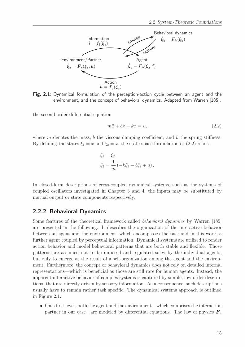
2.2 System-Theoretic Foundations
Environment/Partner
ξe = F e(ξe,u)
Informationi = f i(ξe)
Agent
ξa = F a(ξa, i)
Actionu = fu(ξa)
emerg
e
captur
e
Behavioral dynamics
ξb = F b(ξb)
Fig. 2.1: Dynamical formulation of the perception-action cycle between an agent and theenvironment, and the concept of behavioral dynamics. Adapted from Warren [185].
the second-order differential equation
mx+ bx+ kx = u, (2.2)
where m denotes the mass, b the viscous damping coefficient, and k the spring stiffness.
By defining the states ξ1 = x and ξ2 = x, the state-space formulation of (2.2) reads
ξ1 = ξ2
ξ2 =1
m(−kξ1 − bξ2 + u) .
In closed-form descriptions of cross-coupled dynamical systems, such as the systems of
coupled oscillators investigated in Chapter 3 and 4, the inputs may be substituted by
mutual output or state components respectively.
2.2.2 Behavioral Dynamics
Some features of the theoretical framework called behavioral dynamics by Warren [185]
are presented in the following. It describes the organization of the interactive behavior
between an agent and the environment, which encompasses the task and in this work, a
further agent coupled by perceptual information. Dynamical systems are utilized to render
action behavior and model behavioral patterns that are both stable and flexible. Those
patterns are assumed not to be imposed and regulated soley by the individual agents,
but only to emerge as the result of a self-organization among the agent and the environ-
ment. Furthermore, the concept of behavioral dynamics does not rely on detailed internal
representations—which is beneficial as those are still rare for human agents. Instead, the
apparent interactive behavior of complex systems is captured by simple, low-order descrip-
tions, that are directly driven by sensory information. As a consequence, such descriptions
usually have to remain rather task specific. The dynamical systems approach is outlined
in Figure 2.1.
• On a first level, both the agent and the environment—which comprises the interaction
partner in our case—are modeled by differential equations. The law of physics F e
15
2 Conceptual Foundations
governs the environmental state ξe. An information function f i accounts for the
perceptual processing of certain environmental properties through vision, haptics,
and other modalities into informational variables i. Those are input to the agent’s
law of control F a, which determines the evolution of the state ξa as a description
of the agent’s action behavior. The perception-action cycle is closed by the effector
function fu, which transforms the action state into external forces u applied to the
environment.
• On the second level of description, the concept of behavioral dynamics now seeks to
capture the emergent behavior of the perception-action cycle by a high-level dynam-
ical system F b, which is expressed in behavioral state variables ξb. Thus, both levels
of description are linked bidirectionally.
Dynamical systems theory provides an elegant language to characterize motor behavior.
Stable solutions, to which the state of the dynamical system converges are called attractors,
and unstable ones, from which the state diverges are called repellers. Among the variety of
attractors, two types are of particular interest in this work, as they are the building blocks
for modeling stable interactive behavior by means of the dynamical systems approach:
• Stable fixed points (point attractors) model behavior tending towards stable equilib-
rium values, which may represent individual or collective goals of the agents with
respect to the task. In contrast, unstable fixed points (repellers) allows to model
avoidance behavior of undesired states. Later, we will make use of fixed points in the
phase difference dynamics to replicate preferred phase relations of interacting human
dyads in Chapter 3, and to model enhanced entrainment modes among human-robot
dyads in Chapter 4.
• Closed periodic orbits (stable limit cycle attractors) model behavior tending towards
stable, self-sustained oscillations, such as the execution of repetitive action tasks
under spatial task constraints. Limit cycles exhibit one neutral DoF that may be
subject to adaptation, while the remaining DoF are stable and resist perturbations.
Limit cycle systems are characterized further in Section 4.2.1.
The stability of these attractors is modulated by their attractor strength or their corre-
sponding relaxation time respectively, which determines how fast perturbations away from
equilibrium decay.
Remark 2.2 Continuous re-parameterization of the dynamical system by so-called control
parameters may lead to bifurcations, which denote topological or structural changes of the
attractors through a changing morphology of the vector field. Besides the aforementioned
attractors, bifurcations represent another powerful tool in the framework of behavioral
dynamics. For instance, the bifurcation property of dynamical systems is exploited in
the Haken-Kelso-Bunz model to replicate behavioral transitions, which are induced by the
suddenly changing number of attractors depending on a continuous change of the control
parameter [53].
16
2.2 System-Theoretic Foundations
2.2.3 System Identification
The goal of system identification is to build mathematical models, e.g. dynamical systems,
by recording and analyzing accessible observations, i.e. the input and the output data from
the system under consideration [93]. The procedure involves the following three points:
• The data set, which consists of recorded input and output data, usually by means of
discrete sampling. Notably, the design of the identification experiment needs to aim
at maximizing the informational content in the data set.
• The set of candidate models providing the model structure. Their choice usually de-
pends on physical considerations, or a-priori principal knowledge. Model sets without
parameters of explicit physical meaning are called non-parametric models or black-box
models. For their identification, e.g. the impulse or frequency response is analyzed.
In contrast, gray-box models are parametric models, that feature parameters with a
physical meaning associated.2 Due to their relevance in this work, we will focus on
the identification of gray-box models.
• The identification method, which includes the criterion to assess the set of candi-
date models based on the data set, and the algorithm to numerically compute the
estimates.
Often, alterations to those three points have to be made, in order to iteratively converge
to a satisfactory model quality. A comprehensive background on the wide field of system
identification is given in [93, 94].
Prediction-Error Method (PEM) for Gray-Box Identification
For a single-input-single-output system, we assume that pairs of input samples u(t) ∈ R
and output samples y(t) ∈ R are measured at discrete times t = 1, 2, . . . , N , such that we
obtain the data set
ZN = {u(1), y(1), u(2), y(2), . . . , u(N), y(N)} . (2.3)
Remark 2.3 For systems without any measured input u, the problem of system identi-
fication reduces to the identification of time-series models, also called signal models. A
typical example is to estimate through gray-box identification the coefficients of ordinary
differential equations to fit a given response trajectory y(t).
Assuming further, that we decided for a particular model structure, a corresponding one-
step ahead predictor needs to be found, taking the general form
y(t|θ) = g(t, Zt−1,θ), (2.4)
with y(t|θ) being the predicted output at time t and θ ∈ Dθ ⊂ Rd gathering the d
parameters of the model.
2For completeness, so-called white-box models seek to describe the system internals on a physical basisas detailed as possible.
17
2 Conceptual Foundations
Remark 2.4 For the special case of a noise-free model, the model structure itself, e.g. of
the form (2.1), represents a predictor, which is then called a simulation model.
The prediction error sequence for t = 1, . . . , N is then constructed by
e(t,θ) = y(t)− y(t|θ). (2.5)
The idea of PEM is to select the parameter estimate θN based on ZN such, that the
prediction errors e(t, θN) become as small as possible. Hence, the norm or validity mea-
sure VN(θ, ZN ) : Rd × RN → R defined as
VN(θ, ZN ) =
1
N
N∑
t=1
l(e(t,θ)) (2.6)
is calculated. Different types of the scalar function l in (2.6) exist, with the quadratic
form l(e) = e2 being a standard choice. Furthermore, linear filters may be deployed
to e(t,θ) prior to the calculation of (2.6), in order to suppress eventual high-frequency
disturbances or low-frequency drifts. Finally, the parameter estimate θN is obtained as
the solution of the minimization problem
θN = arg minθ∈Dθ
VN (θ, ZN ). (2.7)
In general, (2.7) cannot be solved analytically. Iterative search methods need to be deployed
to compute numerical solutions. Software tools such as theMATLAB System Identification
Toolbox provide efficient gradient estimation techniques and search methods.
Remark 2.5 Unknown initial states of the model may be co-estimated with the param-
eters, which renders especially useful for systems with rather slow dynamics compared to
the length N of the data set.
2.3 Studying Human Interactive Behavior
The proposed design methodology relies on profound experimental studies. At the very be-
ginning of the design process, well-posed experimental designs are required for a systematic
analysis, modeling and identification of the interactive behavior in HHI settings. Similarly,
after the development of behavioral models and prototyping of interactive behavior for
robots, the evaluation is again based on human studies, which are at this stage conducted
in HRI settings. Both the aspects of experimental design and the evaluation techniques
presented in the following focus on the field of joint motor action, which is central to this
work.
18
2.3 Studying Human Interactive Behavior
2.3.1 Aspects of Psychological Experiments
Factors, Conditions and Disturbances
The scientific investigation of interactive behavior through psychological experiments in-
volves the intentional and systematic manipulation and observation of multiple variables.
Two types of variables are of fundamental importance: The independent variables, also
called factors or treatments, are actively manipulated, and the effects on the behavior
are observed by means of the dependent variables, also called measures. Specifically, the
initial condition of interaction and the type of interactive behavior rendered by the robot
are introduced as factors in this work. While the former serves the identification of hu-
man interactive behavior at an early stage of the design process, the latter enables the
evaluation of the developed robotic behavior at the final stage.
The levels of the factors are denoted the experimental conditions, which are system-
atically varied by the experimenter according to the experimental design. At least two
different levels of each factor must be chosen. Referring to the factors relevant in this
work, a number of different initial conditions are applied to human dyads, in order to ob-
serve their corresponding response dynamics, and a number of different behavioral models
are applied to the artificial interaction partner. Those may differ only regarding the model
parameters or the whole model structure.
Remark 2.6 For comparative evaluation of advanced behavioral models, one model may
be designated a baseline condition implementing a ”standard” behavior, which is repro-
ducible by common state-of-the-art methods.
Additionally, a number of unsystematic influences or disturbances effect the dependent
variables, and thus, may confound the experiment. Relevant disturbances in human be-
havior studies include the expectation and motivation of the participants, visual or auditive
distraction of the participants, or unintended ambiguities in the task instruction and exe-
cution. Ideally, all relevant influences are either eliminated or controlled, e.g. kept constant
by following a standardized experimental procedure.
Experimental Design
The variability of human behavior poses particular challenges for the design of experimen-
tal studies. Both person-specific differences and changes of the behavior over time due to
adaptation processes may act as disturbances. One of the goals of a thorough experimen-
tal design is to counteract such influences. In a within-subject design, each participant is
presented multiple conditions of the factors, in contrast to a between-subject design, where
each participant experiments with only one condition. The former is adopted in this work,
since it allows to compare the behavioral changes of different conditions immediately within
one individual, which eliminates person-specific disturbances. Within-subject designs, also
called repeated measures designs, often present the same combination of experimental con-
ditions multiple times to account for the variabilities of human motor behavior. However,
counter-balancing or randomization of the conditions has to be applied, to compensate for
practice effects due to sequential testing.
19

2 Conceptual Foundations
Remark 2.7 Many studies on human-human motor behavior introduce control conditions
to investigate the effect of the partner, i.e. the task is also performed by a single participant
and compared to the dyadic condition. Other control conditions investigate the effect of
certain sensory modalities, e.g. the availability of haptic feedback from the object and/or
the partner during task execution is manipulated.
The studies reported in this work aim to explore human behavior in natural and interactive
settings, thus, the experimental tasks are performed only in joint action—indeed, all except
one inevitably require joint action. Visual and haptic feedback is left unconstrained.
The quality of an experimental study is assessed by its validity. The internal validity
refers to the unique interpretability and consistency of the results, whereas the external
validity refers to the generalizability of the results beyond the experimental setting. Strong
influence has the chosen sample size, i.e. the number of units of analysis. In this work, the
unit of analysis is a dyad of participants in the HHI experiment, with each participant being
part of one dyad only, and an individual participant in the HRI experiments. Sophisticated
methods exist to choose the sample size depending e.g. on the desired effect sizes. As a
rule of thumb, at least ten units of analysis are recommended to allow for statistical
inference. Statistical analysis is required to distinguish if measures are affected by the
experimental conditions or simply by noise, and to infer on a larger population than the
sample population. Seeking to maximize both internal validity and external validity usually
leads to a trade-off, which is illustrated by means of the experimental setting: In laboratory
experiments, disturbance variables can be effectively eliminated, which in general leads
to a high internal validity of the experiment. At the same time, the generalizability is
constrained due to the artificial environment, which might lead to low external validity.
In contrast, field experiments allow for realistic surroundings, and therefore yield high
external validity, while uncontrolled disturbances often shrink their internal validity.
Remark 2.8 Some works that employ field experiments in the domain of HRI are found
in the literature, see e.g. [186]. Mostly, communication aspects of social interaction are
investigated, without robotic manipulation being involved. Field studies on joint action
behavior, however, carried out e.g. in natural domestic environments, would induce severe
concerns regarding the safety and the dependability of state-of-the-art robotic prototypes
in shared workspaces.
This work employs solely laboratory experiments. Notably, the validity of those is addi-
tionally influenced by the type of the interaction scenarios, as discussed in the following.
Virtual vs. Real Interaction Scenarios
In research studies on haptic HHI and HRI, particularly pHRI, interaction tasks are often
simulated in VR environments due to some benefits compared to real world environments:
VR studies with humans can be conducted in an ultimately controlled environment, i.e. the
interaction situations are standardized and well reproducible with high internal validity.
The feedback modalities available to the user are fully controllable, e.g. the goal points
or the instructed configuration trajectory may be hidden or blurred. High-fidelity haptic
20
2.3 Studying Human Interactive Behavior
interaction with a virtual partner is usually realized at low expenses regarding the hard-
ware setup and software development, in particular when focusing on interaction in one or
only few task-related DoF. The task characteristics, such as the workspace requirements
can be matched to the technical specifications of the available haptic device. Furthermore,
many haptic devices provide force and position measurements of high quality at the human
interaction point. Any other physical variables can be derived from the physical simula-
tion of the virtual environment. Consequently, complex data acquisition systems become
unnecessary in many cases. In short, experiments conducted in VR interaction scenarios
achieve high internal validity due to their precise measurements and effectively controlled
or eliminated disturbance variables. This makes them well suited for fundamental research
on human interactive behavior.
However, the external validity of VR experiments is often limited. Joint action scenarios
have to be complemented by visual feedback to render natural interaction. High degrees of
user immersion into the VR environment requires realistic visual rendering and advanced
visual displays, such as head-mounted displays with a high resolution and a large field
of view at low weight. Particularly in joint motor action which physically changes the
environment, it is believed that an ultimate feeling of presence is hard to create in human
participants. For instance, physical embodiment positively affects social interaction when
compared to a virtual partner [182]. The interaction and co-location with a physically
embodied robot is considered essential to conclude on the generalizability of evaluations.
Besides the proof of concept provided by the implementation of real interaction scenarios,
the evaluation of embodied HRI gives valuable feedback on the progress of both research
and development towards the actual goal, which is to build embodied robotic partners
sharing their workspace with humans in real world applications. Thus, HRI experiments
are indispensable for evaluations with high external validity.
2.3.2 Experimental Measures
Both for modeling and evaluation of interactive behavior, relevant dependent variables
have to be selected for experimental observation from the large amount of potential infor-
mation. Such a variable is defined to assume one concrete value from a set of at least two
possible values at each instant of time. Due to the continuous nature of motor behavior,
many variables in this context are defined on a continuous scale over time, such as posi-
tion and force information in visual-haptic interaction. The corresponding trajectories are
then acquired through sampling at discrete time steps, such that time-series data of that
variables are available for each trial of the experimental task. For their interpretation, spe-
cific parameters, behavioral patterns and pattern formation processes need to be identified
through trajectory analysis, statistical analysis or control-theoretic modeling [50], where
characteristic parameters are extracted based on the underlying model assumption.
In the following, two important classes of behavioral measures with relevance to joint
motor action are discussed by means of popular examples, which are performance measures
and effort measures. Furthermore, subjective measures acquired by means of questioning
the participants are distinguished.
21
2 Conceptual Foundations
Performance Measures
Many performance measures are accuracy related, which makes them dependent on the
goals of the specific task. For instance, in so-called tracking tasks, where a moving target
or a given path has to be pursued as exactly as possible, the tracking performance of the
participant is measured by means of the deviation of his/her interaction point or cursor
from the instructed reference [34]. Scalar measures of the tracking quality are obtained e.g.
from the root-mean-square (RMS) deviation accumulated over the position trajectory of
each trial. Remarkably, this performance measure is applicable mainly in VR experiments,
since predefined paths rarely exist in real world tasks. Also, the desired path of human
participants is practically not assessable, unless indirectly by instructing it. In goal-hitting
or positioning tasks, the deviations from a number of known, predefined goal points may
be measured alternatively [194]. Depending on the task, more specific failure measures
include the number or the duration of collisions with obstacles and forbidden regions, or
missed goal configurations.
Generic speed assessment provides the task completion time. However, similar to
accuracy-related measures, the completion time strongly depends on how the participants
are instructed to perform the task, since the human performance is subject to the speed-
accuracy trade-off found by Fitts [35]. Depending on the task goals, typical instructions
encourage the participants to perform e.g. as fast as possible, as precise as possible, or at
comfortable speed.
Remark 2.9 The motor capabilities of robotic prototypes designed for HRI, such as an-
thropomorphic and humanoid robots, are limited regarding movement velocity, acceleration
and output force due to their technical specifications and safety reasons. Those capabilities
are below that of humans for many state-of-the-art robots. Both the experimental task
and the task instruction have to be designed such, that the required task effort and the hu-
man performance meet the robotic motor capabilities, in order to allow for an undistorted
evaluation of human-robot joint action.
The behavioral measures described above can be calculated both for individual and joint
performance of motor tasks. Due to relevance within this work, the degree of synchroniza-
tion between two agents is introduced to quantitatively assess emerging patterns in a pair
of simultaneously recorded movement trajectories. This behavioral measure focuses on the
behavioral relationship of the partners, rather than on criteria straightforwardly derived
from the objective goals of a motor task. Nevertheless, the group of synchronization mea-
sures introduced later in this work is regarded to be related to the task performance, since
synchronization is expected to support mutual coordination and predictability of actions.
Effort Measures
The physical effort arising from haptic interaction is quantified by measures that are derived
from physical variables and based on force components. First of all, the magnitude of
the interaction force represents a basic measure by itself. It is taken at the interface
between the agent and the manipulated object, the partner or the haptic device. Since
environmental changes during physical cooperation are effected through both motion and
22
2.3 Studying Human Interactive Behavior
forces, power and energy variables are further representative measures. Their calculation
requires motion and force referred to the same location of the considered interface. Again,
taking the magnitude accumulates both flow directions in the effort measure, because at
least the human partner is unable to recoup energy, e.g. through deceleration.
Remark 2.10 In pHRI experimental setups, grasp points are often realized by designated
handles, each with a force sensor attached to directly acquire the interaction forces. Since
usually separate data acquisition systems are employed for force and motion measure-
ment, their time series data have to be synchronized thoroughly to avoid artifacts in the
calculation of power and energy measures.
More specific measures are derived by decomposing the interaction force into the external
(motion-causing) force component and the internal (squeezing or stretching) force compo-
nent. The latter, also called interactive forces [48], provide a measure of the disagreement
among the partners, or the negotiation effort respectively. Higher-level measures found in
literature include efficiency measures relating performance to effort [49] and dominance
measures analyzing each partner’s contribution to the motion-causing effort [48, 130].
Scalar measures that represent whole trials are obtained from integration or averaging
over the time series data. Integral versions should be preferred to the corresponding mean
versions, if the trial durations vary within the experiment.
Those force-based effort measures are biased by the passive dynamics of the human body,
first and foremost the inertial and damping properties, which cause non-zero interaction
forces even for passive body movements. In order to take into account the true, metabolic
effort of the human due to muscle contraction, additional measurements are required.
Physiological measures, such as surface electromyography (EMG) directly determine the
activation level of the contributing muscles.
Subjective Measures
As an additional source of information on the sensation of interaction and the experiences
of the participants, subjective measures acquired by means of questionnaires may comple-
ment the behavioral measures. In particular, this holds true for the evaluation of HRI,
since explicit user feedback may provide valuable hints going beyond pure observation on
how to improve the interactive behavior of robot prototypes in future design iterations.
In contrast to behavioral variables that are continuously available, questionnaires permit
an information acquisition only at discrete instances of time, e.g. before and after the ex-
periment, or between the experimental trials. This fact emphasizes the qualitative nature
of subjective measures. The latent constructs operationalized by questionnaires, such as
the feeling of presence or the feeling of togetherness, are prone to noise and biases. As a
consequence, the reliability and validity of questionnaires is rather sensitive. Indeed, their
construction can be regarded as an entire discipline, which involves the formulation and
wording of questions, their organization as well as the selection of scales and answering
options. The interested reader finds guidelines on the topic in [124]. If existing in the tar-
get domain, it is advisable to administer standardized questionnaires, that are successfully
validated. For instance, in the experimental study on physical cooperation presented in
23
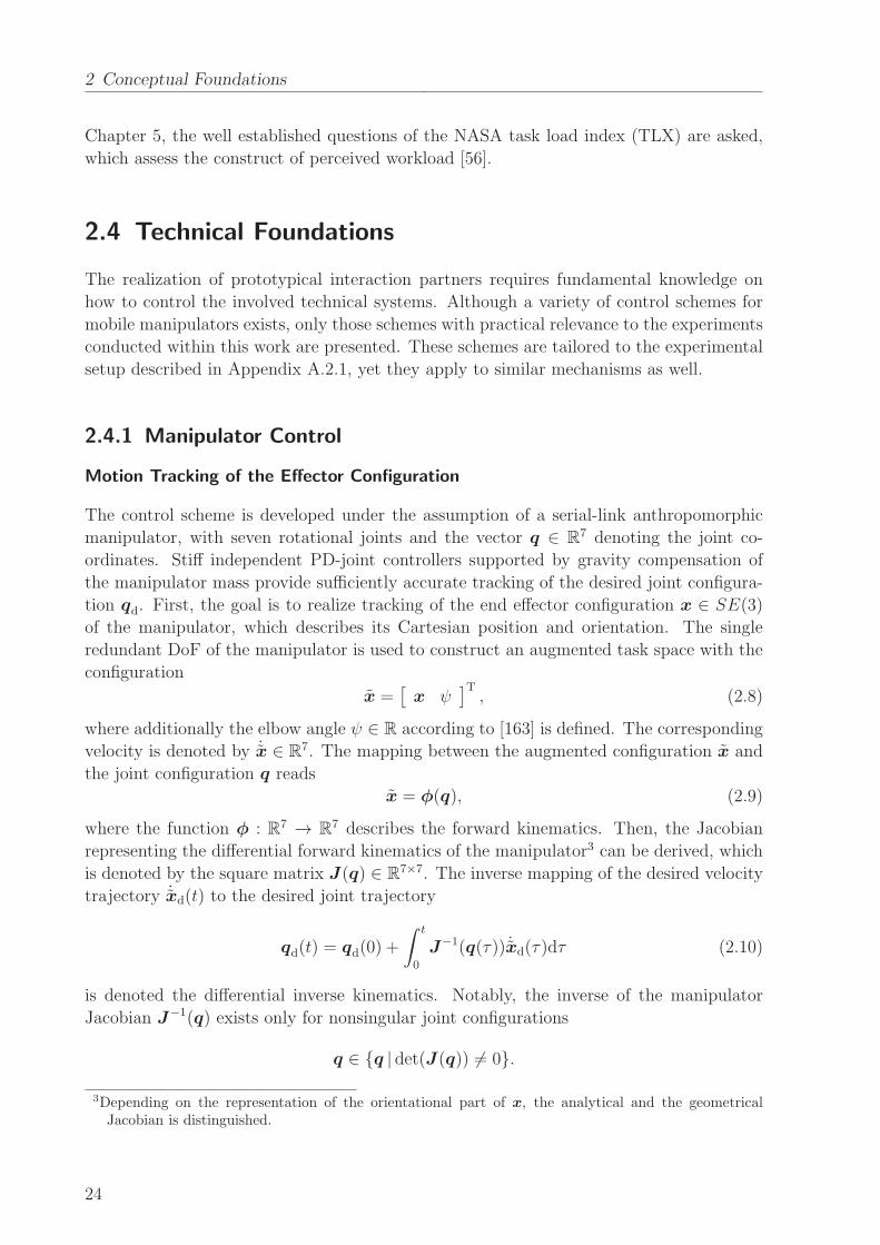
2 Conceptual Foundations
Chapter 5, the well established questions of the NASA task load index (TLX) are asked,
which assess the construct of perceived workload [56].
2.4 Technical Foundations
The realization of prototypical interaction partners requires fundamental knowledge on
how to control the involved technical systems. Although a variety of control schemes for
mobile manipulators exists, only those schemes with practical relevance to the experiments
conducted within this work are presented. These schemes are tailored to the experimental
setup described in Appendix A.2.1, yet they apply to similar mechanisms as well.
2.4.1 Manipulator Control
Motion Tracking of the Effector Configuration
The control scheme is developed under the assumption of a serial-link anthropomorphic
manipulator, with seven rotational joints and the vector q ∈ R7 denoting the joint co-
ordinates. Stiff independent PD-joint controllers supported by gravity compensation of
the manipulator mass provide sufficiently accurate tracking of the desired joint configura-
tion qd. First, the goal is to realize tracking of the end effector configuration x ∈ SE(3)
of the manipulator, which describes its Cartesian position and orientation. The single
redundant DoF of the manipulator is used to construct an augmented task space with the
configuration
x =[
x ψ]T, (2.8)
where additionally the elbow angle ψ ∈ R according to [163] is defined. The corresponding
velocity is denoted by ˙x ∈ R7. The mapping between the augmented configuration x and
the joint configuration q reads
x = φ(q), (2.9)
where the function φ : R7 → R7 describes the forward kinematics. Then, the Jacobian
representing the differential forward kinematics of the manipulator3 can be derived, which
is denoted by the square matrix J(q) ∈ R7×7. The inverse mapping of the desired velocity
trajectory ˙xd(t) to the desired joint trajectory
qd(t) = qd(0) +
∫ t
0
J−1(q(τ)) ˙xd(τ)dτ (2.10)
is denoted the differential inverse kinematics. Notably, the inverse of the manipulator
Jacobian J−1(q) exists only for nonsingular joint configurations
q ∈ {q | det(J(q)) 6= 0}.
3Depending on the representation of the orientational part of x, the analytical and the geometricalJacobian is distinguished.
24
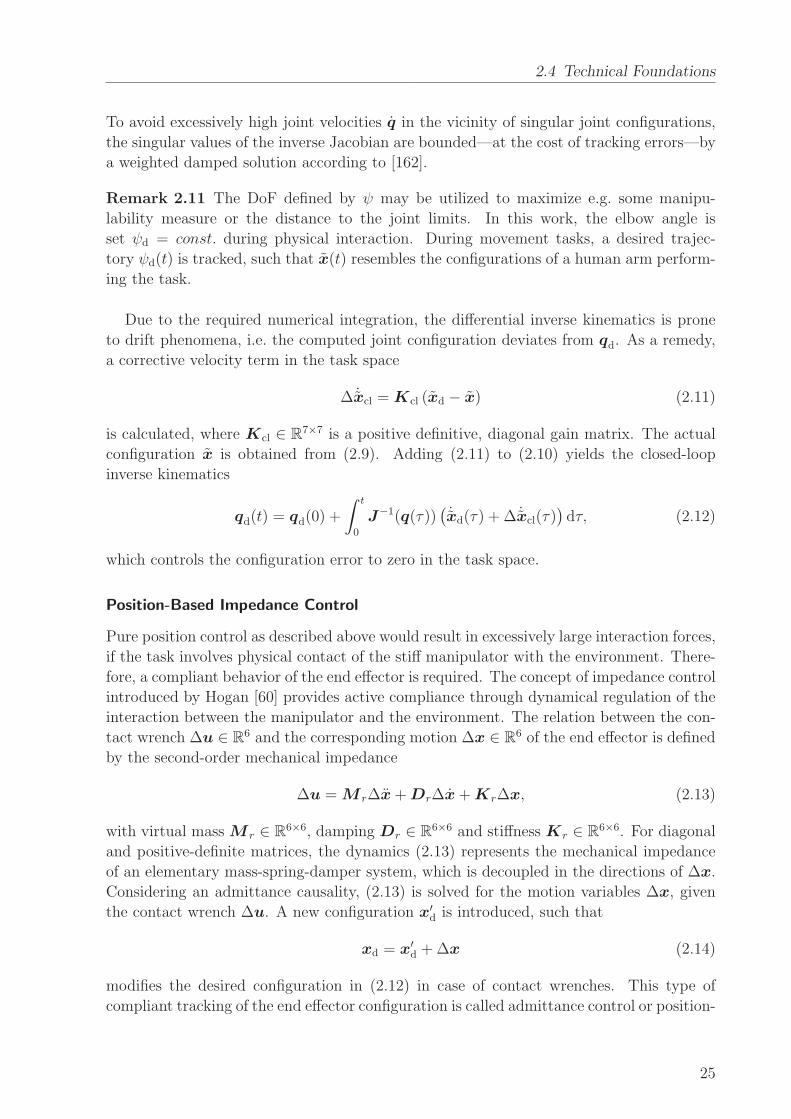
2.4 Technical Foundations
To avoid excessively high joint velocities q in the vicinity of singular joint configurations,
the singular values of the inverse Jacobian are bounded—at the cost of tracking errors—by
a weighted damped solution according to [162].
Remark 2.11 The DoF defined by ψ may be utilized to maximize e.g. some manipu-
lability measure or the distance to the joint limits. In this work, the elbow angle is
set ψd = const. during physical interaction. During movement tasks, a desired trajec-
tory ψd(t) is tracked, such that x(t) resembles the configurations of a human arm perform-
ing the task.
Due to the required numerical integration, the differential inverse kinematics is prone
to drift phenomena, i.e. the computed joint configuration deviates from qd. As a remedy,
a corrective velocity term in the task space
∆ ˙xcl = Kcl (xd − x) (2.11)
is calculated, where Kcl ∈ R7×7 is a positive definitive, diagonal gain matrix. The actual
configuration x is obtained from (2.9). Adding (2.11) to (2.10) yields the closed-loop
inverse kinematics
qd(t) = qd(0) +
∫ t
0
J−1(q(τ))(
˙xd(τ) + ∆ ˙xcl(τ))
dτ, (2.12)
which controls the configuration error to zero in the task space.
Position-Based Impedance Control
Pure position control as described above would result in excessively large interaction forces,
if the task involves physical contact of the stiff manipulator with the environment. There-
fore, a compliant behavior of the end effector is required. The concept of impedance control
introduced by Hogan [60] provides active compliance through dynamical regulation of the
interaction between the manipulator and the environment. The relation between the con-
tact wrench ∆u ∈ R6 and the corresponding motion ∆x ∈ R6 of the end effector is defined
by the second-order mechanical impedance
∆u = M r∆x+Dr∆x+Kr∆x, (2.13)
with virtual mass M r ∈ R6×6, damping Dr ∈ R6×6 and stiffness Kr ∈ R6×6. For diagonal
and positive-definite matrices, the dynamics (2.13) represents the mechanical impedance
of an elementary mass-spring-damper system, which is decoupled in the directions of ∆x.
Considering an admittance causality, (2.13) is solved for the motion variables ∆x, given
the contact wrench ∆u. A new configuration x′d is introduced, such that
xd = x′d +∆x (2.14)
modifies the desired configuration in (2.12) in case of contact wrenches. This type of
compliant tracking of the end effector configuration is called admittance control or position-
25
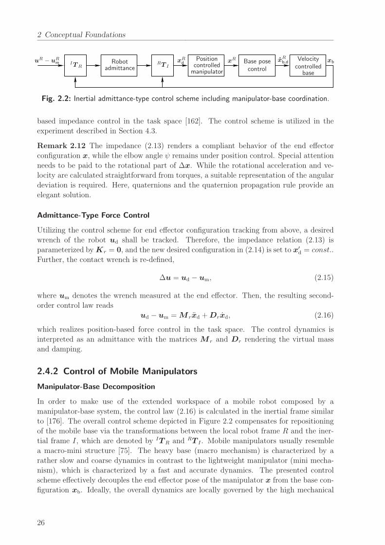
2 Conceptual Foundations
uR − uRm ITR
Robotadmittance
RT I
xRd
Positioncontrolledmanipulator
xR Base posecontrol
xRb,d
Velocitycontrolled
base
xb
Fig. 2.2: Inertial admittance-type control scheme including manipulator-base coordination.
based impedance control in the task space [162]. The control scheme is utilized in the
experiment described in Section 4.3.
Remark 2.12 The impedance (2.13) renders a compliant behavior of the end effector
configuration x, while the elbow angle ψ remains under position control. Special attention
needs to be paid to the rotational part of ∆x. While the rotational acceleration and ve-
locity are calculated straightforward from torques, a suitable representation of the angular
deviation is required. Here, quaternions and the quaternion propagation rule provide an
elegant solution.
Admittance-Type Force Control
Utilizing the control scheme for end effector configuration tracking from above, a desired
wrench of the robot ud shall be tracked. Therefore, the impedance relation (2.13) is
parameterized byKr = 0, and the new desired configuration in (2.14) is set to x′d = const..
Further, the contact wrench is re-defined,
∆u = ud − um, (2.15)
where um denotes the wrench measured at the end effector. Then, the resulting second-
order control law reads
ud − um = M rxd +Drxd, (2.16)
which realizes position-based force control in the task space. The control dynamics is
interpreted as an admittance with the matrices M r and Dr rendering the virtual mass
and damping.
2.4.2 Control of Mobile Manipulators
Manipulator-Base Decomposition
In order to make use of the extended workspace of a mobile robot composed by a
manipulator-base system, the control law (2.16) is calculated in the inertial frame similar
to [176]. The overall control scheme depicted in Figure 2.2 compensates for repositioning
of the mobile base via the transformations between the local robot frame R and the iner-
tial frame I, which are denoted by IT R and RT I . Mobile manipulators usually resemble
a macro-mini structure [75]. The heavy base (macro mechanism) is characterized by a
rather slow and coarse dynamics in contrast to the lightweight manipulator (mini mecha-
nism), which is characterized by a fast and accurate dynamics. The presented control
scheme effectively decouples the end effector pose of the manipulator x from the base con-
figuration xb. Ideally, the overall dynamics are locally governed by the high mechanical
26
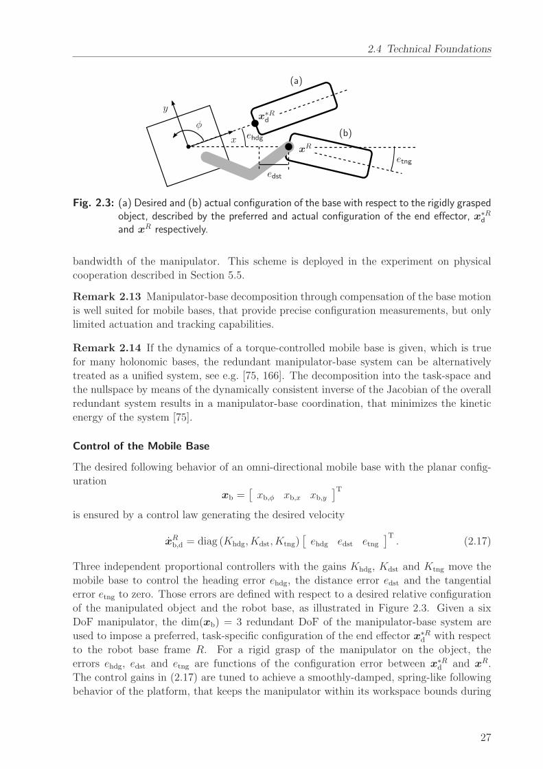
2.4 Technical Foundations
ehdg
edst
etngxR
x∗Rd
(a)
(b)x
y
φ
Fig. 2.3: (a) Desired and (b) actual configuration of the base with respect to the rigidly graspedobject, described by the preferred and actual configuration of the end effector, x∗R
d
and xR respectively.
bandwidth of the manipulator. This scheme is deployed in the experiment on physical
cooperation described in Section 5.5.
Remark 2.13 Manipulator-base decomposition through compensation of the base motion
is well suited for mobile bases, that provide precise configuration measurements, but only
limited actuation and tracking capabilities.
Remark 2.14 If the dynamics of a torque-controlled mobile base is given, which is true
for many holonomic bases, the redundant manipulator-base system can be alternatively
treated as a unified system, see e.g. [75, 166]. The decomposition into the task-space and
the nullspace by means of the dynamically consistent inverse of the Jacobian of the overall
redundant system results in a manipulator-base coordination, that minimizes the kinetic
energy of the system [75].
Control of the Mobile Base
The desired following behavior of an omni-directional mobile base with the planar config-
uration
xb =[
xb,φ xb,x xb,y]T
is ensured by a control law generating the desired velocity
xRb,d = diag (Khdg, Kdst, Ktng)
[
ehdg edst etng]T. (2.17)
Three independent proportional controllers with the gains Khdg, Kdst and Ktng move the
mobile base to control the heading error ehdg, the distance error edst and the tangential
error etng to zero. Those errors are defined with respect to a desired relative configuration
of the manipulated object and the robot base, as illustrated in Figure 2.3. Given a six
DoF manipulator, the dim(xb) = 3 redundant DoF of the manipulator-base system are
used to impose a preferred, task-specific configuration of the end effector x∗Rd with respect
to the robot base frame R. For a rigid grasp of the manipulator on the object, the
errors ehdg, edst and etng are functions of the configuration error between x∗Rd and xR.
The control gains in (2.17) are tuned to achieve a smoothly-damped, spring-like following
behavior of the platform, that keeps the manipulator within its workspace bounds during
27

2 Conceptual Foundations
mobile manipulation. The velocity command xRb,d is then executed by an omni-directional
velocity control law as proposed in [112].
Remark 2.15 The preferred configuration of the end effector x∗Rd can be chosen to meet
e.g. some lower bound wl ∈ R+ of the velocity manipulability measure
w(q) =
√
det(
J (q)J (q)T)
> wl ∀ q ∈ Dw.
The domain
Dw = {q | ‖x∗Rd − φ(q)‖ < ∆xR
w}considers joint configurations within the workspace centered around x∗R
d and bounded
by ∆xRw.
2.5 Summary
In this chapter, the design methodology is introduced, which guides the development of
interactive behavior in this work. The analytical perspective on joint action is suggested
to start with, if the behavioral features of humans are not yet understood completely in
the target domain. The idea is to analyze, model and identify the dynamics of the human
interactive behavior based on HHI experiments. The synthetical perspective is beneficially
applied, if profound knowledge of human behavior already exists in the target domain.
Here, the key components are a representational model of the joint action task and the
corresponding model of human behavior, in order to both predict the partner’s actions
and be predictable for the partner. Each iteration of the design process is completed by
prototyping robotic behavior and evaluating it in HRI experiments. Dynamical systems,
their specific application called behavioral dynamics and gray-box system identification are
introduced as the common modeling tools to capture the dynamic interrelations between
perception and action. Due to their importance in the methodology, we introduce basic
aspects of psychological experiments regarding their design and the deployed measures in
the context of interactive motor behavior. In particular, the validity trade-off between
virtual and real scenarios is discussed. Finally, we present the relevant control techniques
that render the motor actions of a robotic prototype composed by an anthropomorphic
manipulator and a mobile base.
28
3 Modeling of Human Movement Coordination
Humans manage to successfully coordinate their movements in many situations of daily
life. Movement coordination can be intrapersonal (interlimb), e.g. coordination of one’s
left with one’s right arm on a neural basis, or interpersonal, i.e. coordination with another
person through information exchange. There is a wide range of actions that people perform
together in shared workspaces, requiring individual movements to be coordinated. Exam-
ples range from handing over objects, manipulating a common workpiece to setting up a
table. In order to prevent collisions and injuries in the worst case, the agents are required
to keep certain spatial and temporal relations of their actions. People often seem to take
on such coordinative behavior without much effort in a smooth manner. Coordination
often comes about as movement synchronization during repetitive action. Synchronization
refers to the establishment of a bounded temporal relationship between the interacting
entities. It is assumed to be originated and sustained by a convergent dynamical process
spanning across the interacting agents.
The contribution of this chapter is a systematic modeling approach to describe human-
human interactive behavior in a quantitative way. Following the analytical perspective
introduced as part of the methodological concept in Chapter 2, our goal is to provide a
comprehensive description that can be transfered to robots and evaluated in HRI. Three
research questions are addressed in this chapter: First, is movement synchronization ob-
served in rhythmic HHI a phenomenon that also holds in goal-directed tasks? Second,
if yes, when does synchronization between humans emerge during such a task and which
patterns emerge? Third, how can we capture the observed effects in a mathematical
model which is implementable to render corresponding robotic behavior? The presented
experimental study evidences that people also synchronize their arm movements in a goal-
directed task, which is characterized by the need for precise movements. These findings are
in line with previous studies on interpersonal movement coordination in purely rhythmic
tasks [138, 139, 151]. Movement synchronization is found to be guided by a dynamical
process, which leads to stable coordination patterns in natural HHI. From an analytical
and model-directed point of view, we characterize the emerging patterns and the quality of
coordination by the extent of phase synchronization. Through system identification based
on the experimental data, a parameterized model is derived which is ready for implemen-
tation and evaluation in HRI and, thus, lays the foundations for the behavior synthesis
presented in Chapter 4.
This chapter is organized as follows: Section 3.1 provides the reader with an overview
on existing works researching interpersonal movement coordination in the fields of exper-
imental psychology as well as dynamical system theory. The proposed modeling concept
along with the novel task paradigm and the experimental method is described in Sec-
tion 3.2. In Section 3.3, key patterns of human-human synchronization are discovered and
characterized in detail for the sake of modeling. The appropriate model structure is de-
29
3 Modeling of Human Movement Coordination
rived and investigated for its parameter and stability properties in Section 3.4. Parameter
identification is presented jointly with an evaluation of the results here as well. The quan-
titative results obtained from the modeling concept are discussed thoroughly with respect
to their generalizability, explanatory power and methodological issues in Section 3.5. The
chapter finishes in Section 3.6 with the conclusion on the analytical perspective to human
behavioral modeling and open vistas for future research.
3.1 Background
Since modeling of HHI behavior in repetitive movement tasks is the central contribution of
this chapter, we review related work on the exploration and modeling of human movement
coordination in the following. Note that the focus is put on movement synchronization, as
it is considered as key feature of rhythmic movement coordination.
3.1.1 Experimental Studies and Key Results
Numerous studies conducted in the domain of experimental psychology provide evidence for
human movement synchronization. Without stating completeness, we review in the follow-
ing some of the most interesting works that discover features of interpersonal entrainment
in human interactive behavior observed in a variety of action tasks. Mostly, purely rhyth-
mic task paradigms are applied, in which synchronization to in-phase (symmetric) and
anti-phase (alternating) relations is either instructed or observed to spontaneously emerge.
Intentional Entrainment
For dyads sitting side-by-side and moving their lower legs in accordance with a metronome,
coordination breakdown resulting in a transition from the anti-phase to the in-phase mode
is observed with increased frequency [151]. Another popular experimental paradigm is
the swinging of hand-held pendulums while the participants are sitting side-by-side. In
addition to the coupled frequency of oscillations, it allows to manipulate the difference of
the preferred physical frequency of the pendulums as control parameter by changing their
lengths or weights [148]. Shifts of the frequency difference are found to induce correspond-
ing shifts of the stable phase relations during visually coordinated pendulum swinging.
Unintentional Entrainment
The emergence of unintended coordination in the laboratory task of pendulum swinging is
shown as well [150]. It is argued that the same mechanisms of dynamical self-organization
as observed in intrapersonal coordination apply. Similar behavior is observed in [138].
In [139], a paradigm is introduced in which two people are moving forth and back next to
each other in rocking chairs. Dyads unintentionally rock in synchrony, although different
weights attached to the chairs manipulate the frequencies at which they would naturally
oscillate without extra effort. Dyads facing each other and performing oscillatory index
finger movements are also found to unintentionally synchronize by deviating from their
individually preferred frequency [117]. Persistence of entrainment after preventing visual
30
3.1 Background
feedback is attributed to a social memory effect. Similarly, during side-by-side walking
on a treadmill, pairs of participants tend to synchronize their gait to intermittently stable
patterns, even when no instruction to synchronize is given [178]. In addition to extensively
investigated couplings provided through the visual and auditive modality, unintentional
entrainment through haptics is spontaneously emerging as well. Strongest in-phase syn-
chronization during side-by-side walking is found for couples with mutual haptic feedback
through holding hands [193]. Light fingertip contact during rhythmic postural sway seem-
ingly stabilizes spontaneous in-phase coordination within dyads [161].
Social Effects
Besides the above behavioral observations, synchronization affects social relationships.
During observing or listening to simulated dyads walking in different patterns of synchrony,
interpersonal rapport between the walkers is judged highest for the most stable forms of
in-phase and anti-phase coordination [107]. Metronome-paced finger movements that are
synchronous to that of an experimenter leads to higher interpersonal affiliation ratings
than asynchronous tapping [63]. Furthermore, rocking in synchrony enhances perceptual
sensitivity towards each other, and fosters the cooperative abilities in a subsequent joint
action task [177]. Conversely, the individual degree of sociality of interaction partners influ-
ences the extent of synchronization. Regardless if sociality is manipulated through priming
instructions, or resulting from person-specific characteristics, social-oriented participants
achieve a higher degree of synchronization than self-oriented ones during rhythmic arm
movements in [96].
3.1.2 Modeling and Identification Approaches
Movement synchronization—as a basic principle of human interactive behavior—is inves-
tigated repeatedly by means of dynamical systems that model interconnected perception-
action loops and generate dynamical patterns [9, 155]. In this context, the reader is referred
to the comprehensive review on behavioral dynamics provided by Warren [185]. In contrast
to the dynamical systems approach, the research domain of sensorimotor synchronization
(SMS) usually focuses on discrete linear modeling from an information-processing point of
view. Insights to be gained from relevant works on SMS will be reviewed in Chapter 4.
Intrapersonal Movement Coordination – the Haken-Kelso-Bunz Model
Pioneering work on modeling intrapersonal coordination of limbs is conducted by Haken
et al. [53]. The authors propose a minimal dynamical model of coupled nonlinear
oscillators—known as the Haken-Kelso-Bunz (HKB) model—which successfully reproduces
the transition between stable coordination patterns during bimanual finger-tapping. It is
originated from the theoretical framework of synergetics [52], which describes the self-
organized interplay of many DoF in the (human motor control) system by one or few
order parameters or collective variables respectively. Those are slowly changing in time
and represent stable coordinative states at a macroscopic level, which are the in-phase and
anti-phase relation in the finger tapping task. The system may be driven through its co-
31
3 Modeling of Human Movement Coordination
ordinative states by the control parameter, such as an external pacing frequency provided
through a metronome. For the task of bi-manual finger tapping, the phase difference Φ
taken from the phases of the oscillatory finger trajectories turns out to be the appropriate
order parameter. For the design of the attractor dynamics Φ = ∂V∂Φ
, Haken et al. [53]
postulate 2π-periodicity, i.e. for the corresponding potential function, V (Φ) = V (Φ + 2π)
holds, and left-to-right symmetry between both hands, i.e. V (−Φ) = V (Φ) holds. The
simplest potential well mapping the observed behavior to the collective dynamics reads
V = −a cosΦ− b cos(2Φ). (3.1)
If the ratio of the parameters bais changed depending on the control parameter, the change
of the attractor basins in the attractor landscape (3.1) well describes the coordination
phenomena: The dynamics bifurcate from bistability between in-phase and anti-phase to
monostability of the in-phase relation, if bais decreased and the frequency is increased
respectively beyond the critical value ba= 0.25.
Remark 3.1 Besides the dynamics at the collective level, a lower-level description is part
of the HKB model, which includes both the phase and the amplitudes of the hand move-
ments. It also accounts for the decreasing amplitudes when increasing the driving fre-
quency.
Several modifications of the HKB model are proposed. Two additional oscillators are intro-
duced in [10] to represent the level of movement generation through the end effectors while
explicitly accounting for the mechanical properties of a human limb. This neuro-mechanical
model should foster the fundamental analysis of the interplay between the neural and the
effector level during simple, purely rhythmic movements. In order to gain deeper insights
into the dynamics of human coordination, experimental paradigms which utilize a human’s
periodical input to drive oscillatory mechanical systems with different eigenfrequencies
are applied repeatedly. The task paradigm of swinging pendulums originally introduced
by Turvey et al. [173] is also employed by Schmidt et al. [152]. An extension of the HKB
coupling function by a frequency detuning term similar to the coupling function proposed
in [18] is found to account for both the effects of different eigenfrequencies and external
forcing frequencies.
Interpersonal Movement Coordination
Originally developed to model intrapersonal coordination of movements, dynamical models
of coupled oscillators are found to qualitatively explain interpersonal coordination as well.
While participants had to swing hand-held pendulums, coordination phenomenons are
matched the predicted features of the HKB model [148]. In a subsequent study, Schmidt
et al. [153] compare the characteristics of intended intra- and interpersonal coordination
by applying the same pendulum paradigm. Frequency detuning imposed through different
eigenfrequencies and frequency levels are introduced as control parameters. Depending
on the frequency level and the intended phase relation, the authors obtain the coupling
strength of a local dynamical model similar to [18]. The number of coordination break-
downs, the phase fluctuation and the coupling strength reveal interpersonal coordination to
32
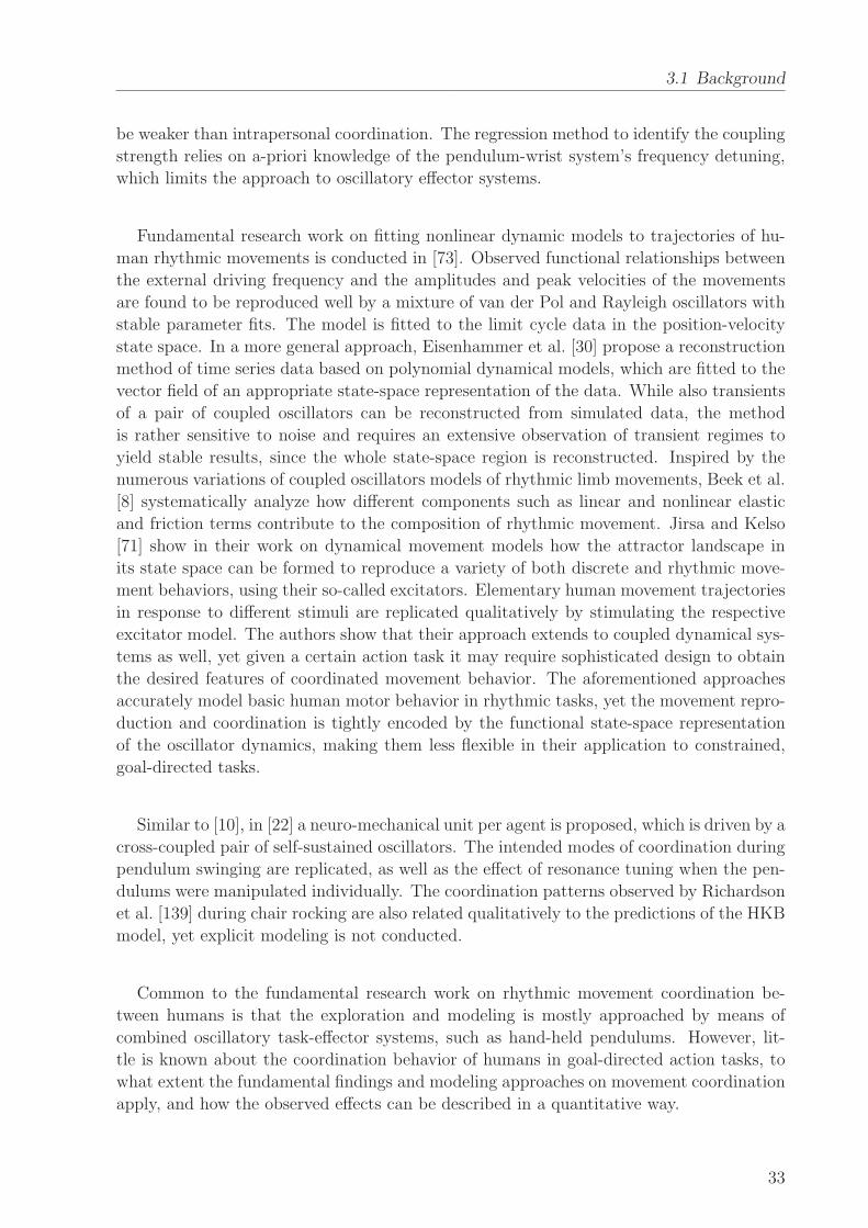
3.1 Background
be weaker than intrapersonal coordination. The regression method to identify the coupling
strength relies on a-priori knowledge of the pendulum-wrist system’s frequency detuning,
which limits the approach to oscillatory effector systems.
Fundamental research work on fitting nonlinear dynamic models to trajectories of hu-
man rhythmic movements is conducted in [73]. Observed functional relationships between
the external driving frequency and the amplitudes and peak velocities of the movements
are found to be reproduced well by a mixture of van der Pol and Rayleigh oscillators with
stable parameter fits. The model is fitted to the limit cycle data in the position-velocity
state space. In a more general approach, Eisenhammer et al. [30] propose a reconstruction
method of time series data based on polynomial dynamical models, which are fitted to the
vector field of an appropriate state-space representation of the data. While also transients
of a pair of coupled oscillators can be reconstructed from simulated data, the method
is rather sensitive to noise and requires an extensive observation of transient regimes to
yield stable results, since the whole state-space region is reconstructed. Inspired by the
numerous variations of coupled oscillators models of rhythmic limb movements, Beek et al.
[8] systematically analyze how different components such as linear and nonlinear elastic
and friction terms contribute to the composition of rhythmic movement. Jirsa and Kelso
[71] show in their work on dynamical movement models how the attractor landscape in
its state space can be formed to reproduce a variety of both discrete and rhythmic move-
ment behaviors, using their so-called excitators. Elementary human movement trajectories
in response to different stimuli are replicated qualitatively by stimulating the respective
excitator model. The authors show that their approach extends to coupled dynamical sys-
tems as well, yet given a certain action task it may require sophisticated design to obtain
the desired features of coordinated movement behavior. The aforementioned approaches
accurately model basic human motor behavior in rhythmic tasks, yet the movement repro-
duction and coordination is tightly encoded by the functional state-space representation
of the oscillator dynamics, making them less flexible in their application to constrained,
goal-directed tasks.
Similar to [10], in [22] a neuro-mechanical unit per agent is proposed, which is driven by a
cross-coupled pair of self-sustained oscillators. The intended modes of coordination during
pendulum swinging are replicated, as well as the effect of resonance tuning when the pen-
dulums were manipulated individually. The coordination patterns observed by Richardson
et al. [139] during chair rocking are also related qualitatively to the predictions of the HKB
model, yet explicit modeling is not conducted.
Common to the fundamental research work on rhythmic movement coordination be-
tween humans is that the exploration and modeling is mostly approached by means of
combined oscillatory task-effector systems, such as hand-held pendulums. However, lit-
tle is known about the coordination behavior of humans in goal-directed action tasks, to
what extent the fundamental findings and modeling approaches on movement coordination
apply, and how the observed effects can be described in a quantitative way.
33
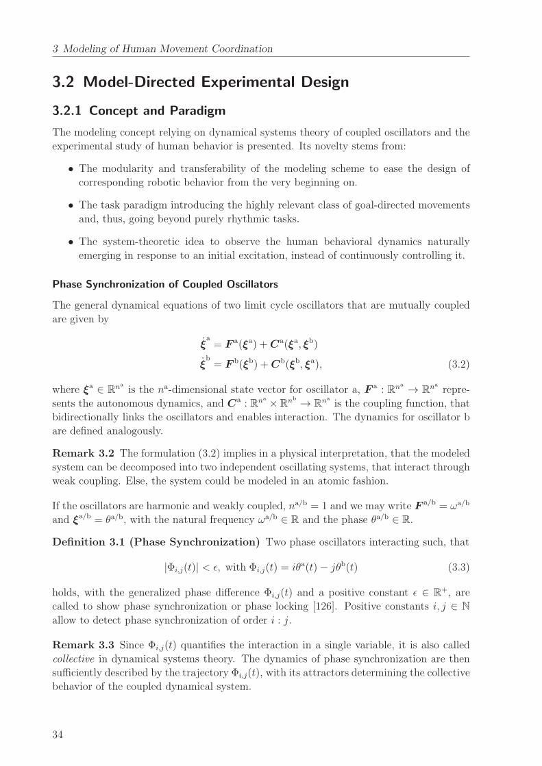
3 Modeling of Human Movement Coordination
3.2 Model-Directed Experimental Design
3.2.1 Concept and Paradigm
The modeling concept relying on dynamical systems theory of coupled oscillators and the
experimental study of human behavior is presented. Its novelty stems from:
• The modularity and transferability of the modeling scheme to ease the design of
corresponding robotic behavior from the very beginning on.
• The task paradigm introducing the highly relevant class of goal-directed movements
and, thus, going beyond purely rhythmic tasks.
• The system-theoretic idea to observe the human behavioral dynamics naturally
emerging in response to an initial excitation, instead of continuously controlling it.
Phase Synchronization of Coupled Oscillators
The general dynamical equations of two limit cycle oscillators that are mutually coupled
are given by
ξa= F a(ξa) +Ca(ξa, ξb)
ξb= F b(ξb) +Cb(ξb, ξa), (3.2)
where ξa ∈ Rna
is the na-dimensional state vector for oscillator a, F a : Rna → Rna
repre-
sents the autonomous dynamics, and Ca : Rna ×Rnb → R
nais the coupling function, that
bidirectionally links the oscillators and enables interaction. The dynamics for oscillator b
are defined analogously.
Remark 3.2 The formulation (3.2) implies in a physical interpretation, that the modeled
system can be decomposed into two independent oscillating systems, that interact through
weak coupling. Else, the system could be modeled in an atomic fashion.
If the oscillators are harmonic and weakly coupled, na/b = 1 and we may write F a/b = ωa/b
and ξa/b = θa/b, with the natural frequency ωa/b ∈ R and the phase θa/b ∈ R.
Definition 3.1 (Phase Synchronization) Two phase oscillators interacting such, that
|Φi,j(t)| < ǫ, with Φi,j(t) = iθa(t)− jθb(t) (3.3)
holds, with the generalized phase difference Φi,j(t) and a positive constant ǫ ∈ R+, are
called to show phase synchronization or phase locking [126]. Positive constants i, j ∈ N
allow to detect phase synchronization of order i : j.
Remark 3.3 Since Φi,j(t) quantifies the interaction in a single variable, it is also called
collective in dynamical systems theory. The dynamics of phase synchronization are then
sufficiently described by the trajectory Φi,j(t), with its attractors determining the collective
behavior of the coupled dynamical system.
34
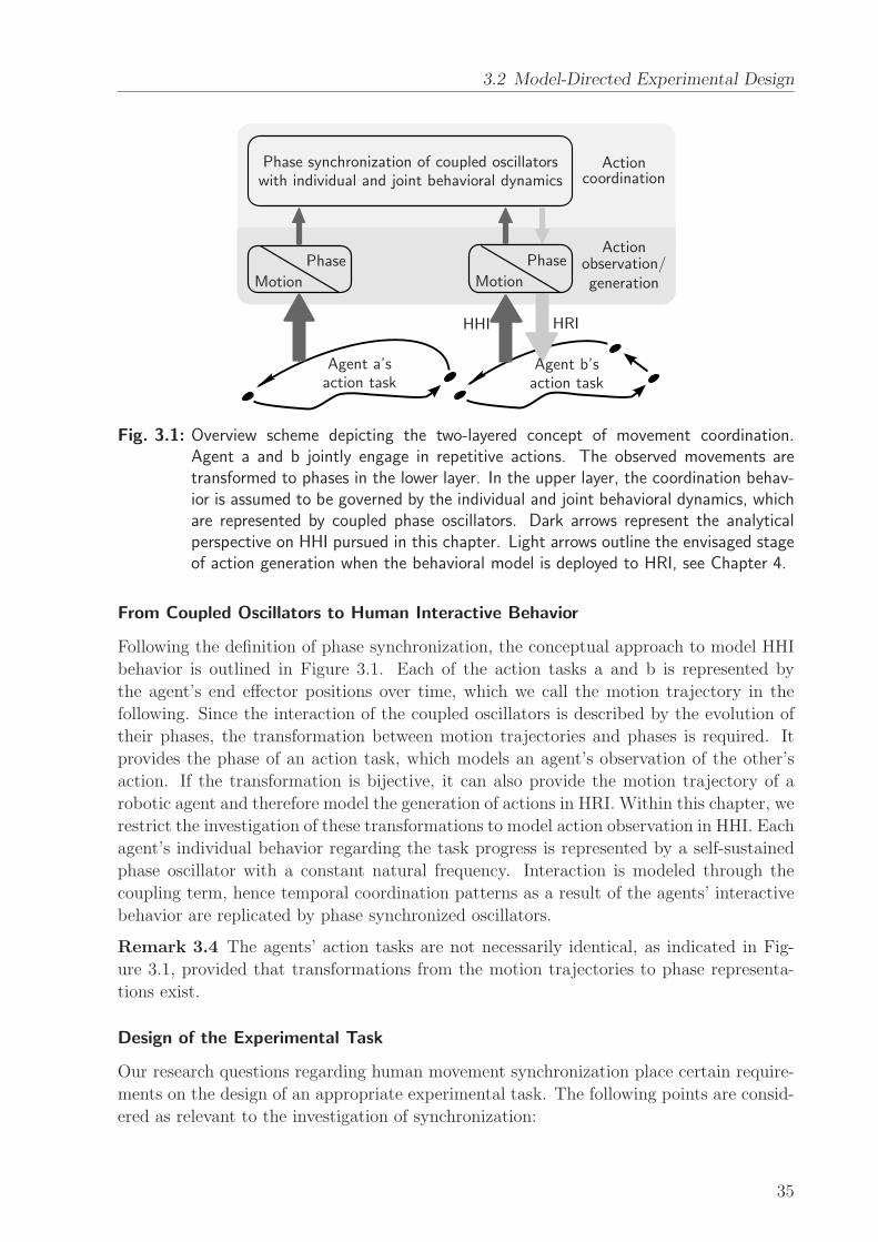
3.2 Model-Directed Experimental Design
Phase synchronization of coupled oscillatorswith individual and joint behavioral dynamics
PhasePhase
MotionMotion
Agent a’saction task
Agent b’saction task
HHI HRI
Actionobservation/generation
Actioncoordination
Fig. 3.1: Overview scheme depicting the two-layered concept of movement coordination.Agent a and b jointly engage in repetitive actions. The observed movements aretransformed to phases in the lower layer. In the upper layer, the coordination behav-ior is assumed to be governed by the individual and joint behavioral dynamics, whichare represented by coupled phase oscillators. Dark arrows represent the analyticalperspective on HHI pursued in this chapter. Light arrows outline the envisaged stageof action generation when the behavioral model is deployed to HRI, see Chapter 4.
From Coupled Oscillators to Human Interactive Behavior
Following the definition of phase synchronization, the conceptual approach to model HHI
behavior is outlined in Figure 3.1. Each of the action tasks a and b is represented by
the agent’s end effector positions over time, which we call the motion trajectory in the
following. Since the interaction of the coupled oscillators is described by the evolution of
their phases, the transformation between motion trajectories and phases is required. It
provides the phase of an action task, which models an agent’s observation of the other’s
action. If the transformation is bijective, it can also provide the motion trajectory of a
robotic agent and therefore model the generation of actions in HRI. Within this chapter, we
restrict the investigation of these transformations to model action observation in HHI. Each
agent’s individual behavior regarding the task progress is represented by a self-sustained
phase oscillator with a constant natural frequency. Interaction is modeled through the
coupling term, hence temporal coordination patterns as a result of the agents’ interactive
behavior are replicated by phase synchronized oscillators.
Remark 3.4 The agents’ action tasks are not necessarily identical, as indicated in Fig-
ure 3.1, provided that transformations from the motion trajectories to phase representa-
tions exist.
Design of the Experimental Task
Our research questions regarding human movement synchronization place certain require-
ments on the design of an appropriate experimental task. The following points are consid-
ered as relevant to the investigation of synchronization:
35
3 Modeling of Human Movement Coordination
Fig. 3.2: Experimental task designed to study HHI behavior. Participants are performing goal-directed arm movements while sitting face to face.
• The task paradigm should integrate goal-directed as well as repetitive actions, which
similarly appear as building blocks in real-life settings. To keep the task simple,
a sequence consisting of a forward and a backward movement has to be performed
repetitively, forming a closed trajectory, which we call the (movement) cycle in the
following. Multiple cycles are to be completed in a continuous sequence, which allows
synchronization to emerge among the agents. The forward as well as the backward
movement (half-cycles) are point-to-point arm movements while carrying a tool in
hand. This is where goal-directedness comes into play: The tool (a pen) has to
be placed on two designated positions on a table alternately. Note that the agents
perform identical tasks.
• The topology of workspaces is arranged without overlap of the movement trajec-
tories. This enables the agents to perform in parallel without any interference or
demand for collision avoidance, which could restrict movement synchronization. The
workspace topology is known to strongly affect the temporal aspects of movement
coordination [156]. Overlaps for example might lead to changes in the coordination
behavior.
• During task execution, the agents’ movements are affected by the type of sensory
information that is available of the other agent’s movements. Regarding visual infor-
mation pick-up, it is known that focal and peripheral conditions of mutual movement
observation mediate the stability of interpersonal coordination [139]. In order to pro-
vide full visual information, the agents are facing each other without any occlusions.
Since they are always able to observe their opponents’ movements as well as start
and target positions, synchronization is made as easy as possible.
The experimental task involving the actions of two agents is illustrated in Figure 3.2.
36
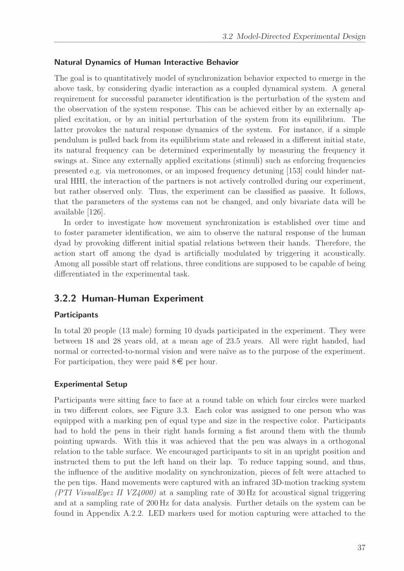
3.2 Model-Directed Experimental Design
Natural Dynamics of Human Interactive Behavior
The goal is to quantitatively model of synchronization behavior expected to emerge in the
above task, by considering dyadic interaction as a coupled dynamical system. A general
requirement for successful parameter identification is the perturbation of the system and
the observation of the system response. This can be achieved either by an externally ap-
plied excitation, or by an initial perturbation of the system from its equilibrium. The
latter provokes the natural response dynamics of the system. For instance, if a simple
pendulum is pulled back from its equilibrium state and released in a different initial state,
its natural frequency can be determined experimentally by measuring the frequency it
swings at. Since any externally applied excitations (stimuli) such as enforcing frequencies
presented e.g. via metronomes, or an imposed frequency detuning [153] could hinder nat-
ural HHI, the interaction of the partners is not actively controlled during our experiment,
but rather observed only. Thus, the experiment can be classified as passive. It follows,
that the parameters of the systems can not be changed, and only bivariate data will be
available [126].
In order to investigate how movement synchronization is established over time and
to foster parameter identification, we aim to observe the natural response of the human
dyad by provoking different initial spatial relations between their hands. Therefore, the
action start off among the dyad is artificially modulated by triggering it acoustically.
Among all possible start off relations, three conditions are supposed to be capable of being
differentiated in the experimental task.
3.2.2 Human-Human Experiment
Participants
In total 20 people (13 male) forming 10 dyads participated in the experiment. They were
between 18 and 28 years old, at a mean age of 23.5 years. All were right handed, had
normal or corrected-to-normal vision and were naıve as to the purpose of the experiment.
For participation, they were paid 8e per hour.
Experimental Setup
Participants were sitting face to face at a round table on which four circles were marked
in two different colors, see Figure 3.3. Each color was assigned to one person who was
equipped with a marking pen of equal type and size in the respective color. Participants
had to hold the pens in their right hands forming a fist around them with the thumb
pointing upwards. With this it was achieved that the pen was always in a orthogonal
relation to the table surface. We encouraged participants to sit in an upright position and
instructed them to put the left hand on their lap. To reduce tapping sound, and thus,
the influence of the auditive modality on synchronization, pieces of felt were attached to
the pen tips. Hand movements were captured with an infrared 3D-motion tracking system
(PTI VisualEyez II VZ4000) at a sampling rate of 30Hz for acoustical signal triggering
and at a sampling rate of 200Hz for data analysis. Further details on the system can be
found in Appendix A.2.2. LED markers used for motion capturing were attached to the
37
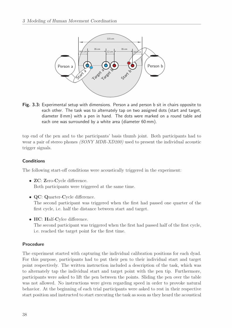
3 Modeling of Human Movement Coordination
Person a
Start a
Targeta
Targetb
Start b
Person b
16,5 cm16,5 cm35 cm35 cm
12 cm
115 cm
Fig. 3.3: Experimental setup with dimensions. Person a and person b sit in chairs opposite toeach other. The task was to alternately tap on two assigned dots (start and target,diameter 8mm) with a pen in hand. The dots were marked on a round table andeach one was surrounded by a white area (diameter 60mm).
top end of the pen and to the participants’ basis thumb joint. Both participants had to
wear a pair of stereo phones (SONY MDR-XD200) used to present the individual acoustic
trigger signals.
Conditions
The following start-off conditions were acoustically triggered in the experiment:
• ZC: Zero-Cycle difference.
Both participants were triggered at the same time.
• QC: Quarter-Cycle difference.
The second participant was triggered when the first had passed one quarter of the
first cycle, i.e. half the distance between start and target.
• HC: Half-Cylce difference.
The second participant was triggered when the first had passed half of the first cycle,
i.e. reached the target point for the first time.
Procedure
The experiment started with capturing the individual calibration positions for each dyad.
For this purpose, participants had to put their pen to their individual start and target
point respectively. The written instruction included a description of the task, which was
to alternately tap the individual start and target point with the pen tip. Furthermore,
participants were asked to lift the pen between the points. Sliding the pen over the table
was not allowed. No instructions were given regarding speed in order to provoke natural
behavior. At the beginning of each trial participants were asked to rest in their respective
start position and instructed to start executing the task as soon as they heard the acoustical
38
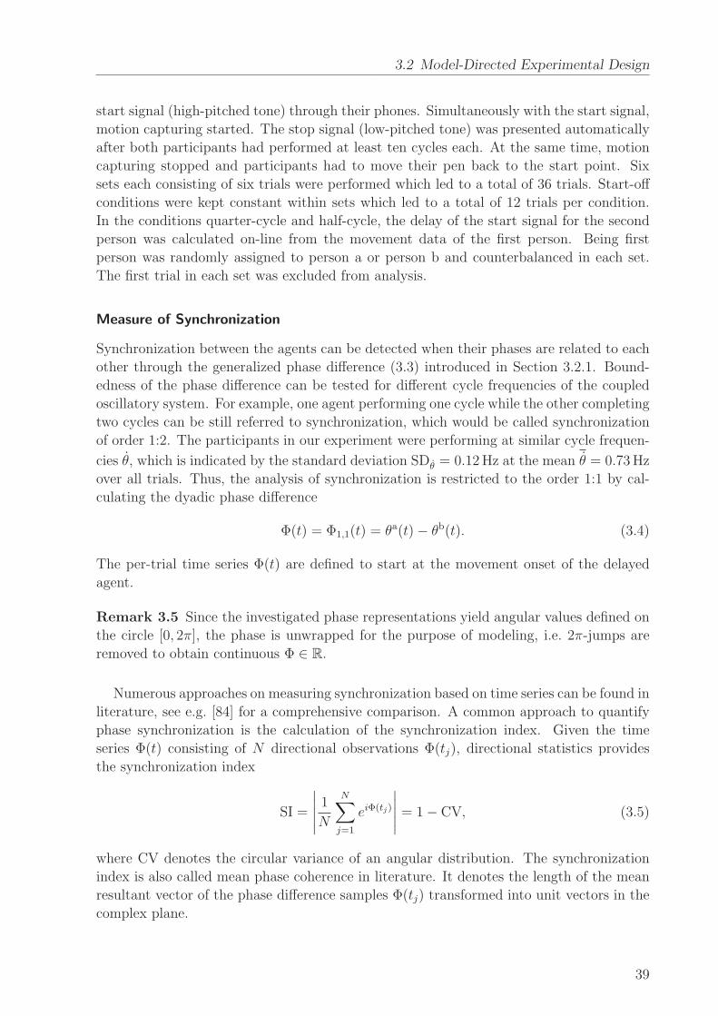
3.2 Model-Directed Experimental Design
start signal (high-pitched tone) through their phones. Simultaneously with the start signal,
motion capturing started. The stop signal (low-pitched tone) was presented automatically
after both participants had performed at least ten cycles each. At the same time, motion
capturing stopped and participants had to move their pen back to the start point. Six
sets each consisting of six trials were performed which led to a total of 36 trials. Start-off
conditions were kept constant within sets which led to a total of 12 trials per condition.
In the conditions quarter-cycle and half-cycle, the delay of the start signal for the second
person was calculated on-line from the movement data of the first person. Being first
person was randomly assigned to person a or person b and counterbalanced in each set.
The first trial in each set was excluded from analysis.
Measure of Synchronization
Synchronization between the agents can be detected when their phases are related to each
other through the generalized phase difference (3.3) introduced in Section 3.2.1. Bound-
edness of the phase difference can be tested for different cycle frequencies of the coupled
oscillatory system. For example, one agent performing one cycle while the other completing
two cycles can be still referred to synchronization, which would be called synchronization
of order 1:2. The participants in our experiment were performing at similar cycle frequen-
cies θ, which is indicated by the standard deviation SDθ = 0.12Hz at the mean θ = 0.73Hz
over all trials. Thus, the analysis of synchronization is restricted to the order 1:1 by cal-
culating the dyadic phase difference
Φ(t) = Φ1,1(t) = θa(t)− θb(t). (3.4)
The per-trial time series Φ(t) are defined to start at the movement onset of the delayed
agent.
Remark 3.5 Since the investigated phase representations yield angular values defined on
the circle [0, 2π], the phase is unwrapped for the purpose of modeling, i.e. 2π-jumps are
removed to obtain continuous Φ ∈ R.
Numerous approaches on measuring synchronization based on time series can be found in
literature, see e.g. [84] for a comprehensive comparison. A common approach to quantify
phase synchronization is the calculation of the synchronization index. Given the time
series Φ(t) consisting of N directional observations Φ(tj), directional statistics provides
the synchronization index
SI =
∣
∣
∣
∣
∣
1
N
N∑
j=1
eiΦ(tj)
∣
∣
∣
∣
∣
= 1− CV, (3.5)
where CV denotes the circular variance of an angular distribution. The synchronization
index is also called mean phase coherence in literature. It denotes the length of the mean
resultant vector of the phase difference samples Φ(tj) transformed into unit vectors in the
complex plane.
39
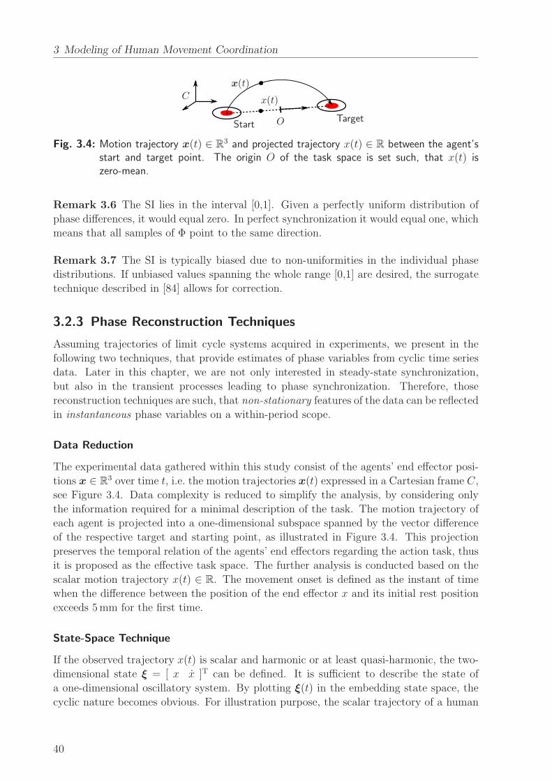
3 Modeling of Human Movement Coordination
x(t)
x(t)C
StartTargetO
Fig. 3.4: Motion trajectory x(t) ∈ R3 and projected trajectory x(t) ∈ R between the agent’s
start and target point. The origin O of the task space is set such, that x(t) iszero-mean.
Remark 3.6 The SI lies in the interval [0,1]. Given a perfectly uniform distribution of
phase differences, it would equal zero. In perfect synchronization it would equal one, which
means that all samples of Φ point to the same direction.
Remark 3.7 The SI is typically biased due to non-uniformities in the individual phase
distributions. If unbiased values spanning the whole range [0,1] are desired, the surrogate
technique described in [84] allows for correction.
3.2.3 Phase Reconstruction Techniques
Assuming trajectories of limit cycle systems acquired in experiments, we present in the
following two techniques, that provide estimates of phase variables from cyclic time series
data. Later in this chapter, we are not only interested in steady-state synchronization,
but also in the transient processes leading to phase synchronization. Therefore, those
reconstruction techniques are such, that non-stationary features of the data can be reflected
in instantaneous phase variables on a within-period scope.
Data Reduction
The experimental data gathered within this study consist of the agents’ end effector posi-
tions x ∈ R3 over time t, i.e. the motion trajectories x(t) expressed in a Cartesian frame C,
see Figure 3.4. Data complexity is reduced to simplify the analysis, by considering only
the information required for a minimal description of the task. The motion trajectory of
each agent is projected into a one-dimensional subspace spanned by the vector difference
of the respective target and starting point, as illustrated in Figure 3.4. This projection
preserves the temporal relation of the agents’ end effectors regarding the action task, thus
it is proposed as the effective task space. The further analysis is conducted based on the
scalar motion trajectory x(t) ∈ R. The movement onset is defined as the instant of time
when the difference between the position of the end effector x and its initial rest position
exceeds 5mm for the first time.
State-Space Technique
If the observed trajectory x(t) is scalar and harmonic or at least quasi-harmonic, the two-
dimensional state ξ = [ x x ]T can be defined. It is sufficient to describe the state of
a one-dimensional oscillatory system. By plotting ξ(t) in the embedding state space, the
cyclic nature becomes obvious. For illustration purpose, the scalar trajectory of a human
40
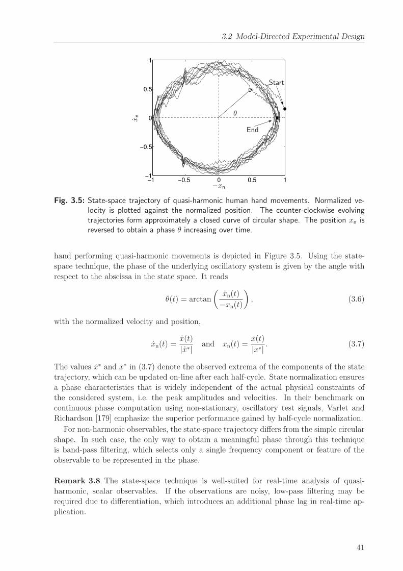
3.2 Model-Directed Experimental Design
−1 −0.5 0 0.5 1−1
−0.5
0
0.5
1
Start
End
θ
−xn
xn
Fig. 3.5: State-space trajectory of quasi-harmonic human hand movements. Normalized ve-locity is plotted against the normalized position. The counter-clockwise evolvingtrajectories form approximately a closed curve of circular shape. The position xn isreversed to obtain a phase θ increasing over time.
hand performing quasi-harmonic movements is depicted in Figure 3.5. Using the state-
space technique, the phase of the underlying oscillatory system is given by the angle with
respect to the abscissa in the state space. It reads
θ(t) = arctan
(
xn(t)
−xn(t)
)
, (3.6)
with the normalized velocity and position,
xn(t) =x(t)
|x∗| and xn(t) =x(t)
|x∗| . (3.7)
The values x∗ and x∗ in (3.7) denote the observed extrema of the components of the state
trajectory, which can be updated on-line after each half-cycle. State normalization ensures
a phase characteristics that is widely independent of the actual physical constraints of
the considered system, i.e. the peak amplitudes and velocities. In their benchmark on
continuous phase computation using non-stationary, oscillatory test signals, Varlet and
Richardson [179] emphasize the superior performance gained by half-cycle normalization.
For non-harmonic observables, the state-space trajectory differs from the simple circular
shape. In such case, the only way to obtain a meaningful phase through this technique
is band-pass filtering, which selects only a single frequency component or feature of the
observable to be represented in the phase.
Remark 3.8 The state-space technique is well-suited for real-time analysis of quasi-
harmonic, scalar observables. If the observations are noisy, low-pass filtering may be
required due to differentiation, which introduces an additional phase lag in real-time ap-
plication.
41
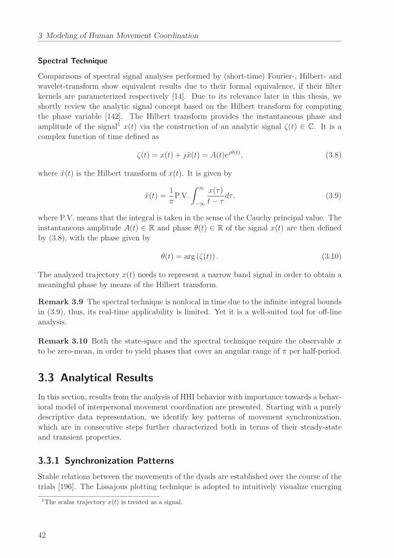
3 Modeling of Human Movement Coordination
Spectral Technique
Comparisons of spectral signal analyses performed by (short-time) Fourier-, Hilbert- and
wavelet-transform show equivalent results due to their formal equivalence, if their filter
kernels are parameterized respectively [14]. Due to its relevance later in this thesis, we
shortly review the analytic signal concept based on the Hilbert transform for computing
the phase variable [142]. The Hilbert transform provides the instantaneous phase and
amplitude of the signal1 x(t) via the construction of an analytic signal ζ(t) ∈ C. It is a
complex function of time defined as
ζ(t) = x(t) + jx(t) = A(t)ejθ(t), (3.8)
where x(t) is the Hilbert transform of x(t). It is given by
x(t) =1
πP.V.
∫ ∞
−∞
x(τ)
t− τdτ, (3.9)
where P.V. means that the integral is taken in the sense of the Cauchy principal value. The
instantaneous amplitude A(t) ∈ R and phase θ(t) ∈ R of the signal x(t) are then defined
by (3.8), with the phase given by
θ(t) = arg (ζ(t)) . (3.10)
The analyzed trajectory x(t) needs to represent a narrow band signal in order to obtain a
meaningful phase by means of the Hilbert transform.
Remark 3.9 The spectral technique is nonlocal in time due to the infinite integral bounds
in (3.9), thus, its real-time applicability is limited. Yet it is a well-suited tool for off-line
analysis.
Remark 3.10 Both the state-space and the spectral technique require the observable x
to be zero-mean, in order to yield phases that cover an angular range of π per half-period.
3.3 Analytical Results
In this section, results from the analysis of HHI behavior with importance towards a behav-
ioral model of interpersonal movement coordination are presented. Starting with a purely
descriptive data representation, we identify key patterns of movement synchronization,
which are in consecutive steps further characterized both in terms of their steady-state
and transient properties.
3.3.1 Synchronization Patterns
Stable relations between the movements of the dyads are established over the course of the
trials [196]. The Lissajous plotting technique is adopted to intuitively visualize emerging
1The scalar trajectory x(t) is treated as a signal.
42

3.3 Analytical Results
Movementpersonb(x
b)[m
]
Movement person a (xa) [m]Start aStart a Target a
Target b
Start b
Cycle 1 Cycle 3 Cycle 6 Cycle 9 ExampleForwardForwardForwardForward BackwardBackwardBackwardBackward
0
0
0
00000000
0.35
0.35
0.350.350.350.350.35
HC
QC
ZC
in-phase
anti-phase
Fig. 3.6: How did synchrony evolve? Visualization of synchronization as Lissajous plots of thehand position of person b relative to that of person a, accumulated in a heat map.Data are plotted separately for the conditions zero-cycle (ZC), quarter-cycle (QC)and half-cycle (HC) as well as for the first, third, sixth and ninth cycle. The dyadstend to synchronize already early in the trial.
synchronization patterns. Position xb of person b is represented as a function of position xa
of person a. In order to capture movement data of all trials, the frequency distribution
is plotted as a heat map, in which brightness codes frequency. For each trial and cycle,
the actual position of person b is determined as a function of person a’s position. The
resulting curves are sampled with an underlying grid of 100 × 100 bins. Forward and
backwards movement are plotted separately, see Figure 3.6. In these plots, perfect 1:1
in-phase or anti-phase synchrony appear as straight diagonal lines, see Figure 3.6 right.
When participants are not perfectly synchronized, data appear curved.
Remark 3.11 The in-phase and the anti-phase relation are particularly easy to identify in
this graphical representation because they appear as straight lines. Other phase relations
show gradually changing elliptic patterns.
Most importantly, the heat map visualizes that in-phase and anti-phase relationships are
already established early in the trial. During the first cycle, data tend to be curved
for all conditions. After that, movements are quickly adapted, which is depicted by the
curves becoming straighter. Data of the zero-cycle condition shows that people are already
almost perfectly adapted to each other after having performed the third cycle. Straight
lines become prevalent indicating in-phase movements. In contrast, during the half-cycle
condition both the in-phase and anti-phase relation are established roughly equally often
until the ninth cycle. Roughly the same result is observed for the quarter-cycle condition,
yet more curved lines appear during the quarter-cycle condition. Constant phase relations
are established later there. This indicates that it is more difficult to establish a stable
in-phase or anti-phase relation when starting off in an odd temporal relation.
43
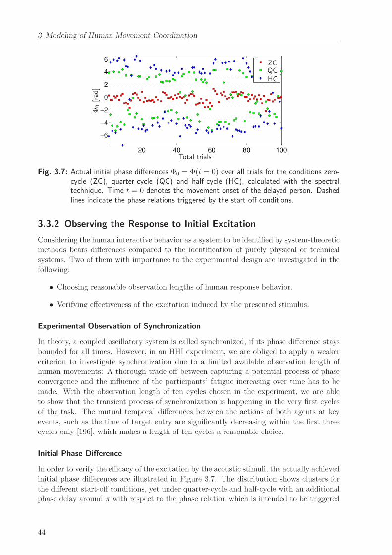
3 Modeling of Human Movement Coordination
20 40 60 80 100
−6
−4
−2
0
2
4
6
Total trials
Φ0[rad]
ZCQCHC
Fig. 3.7: Actual initial phase differences Φ0 = Φ(t = 0) over all trials for the conditions zero-cycle (ZC), quarter-cycle (QC) and half-cycle (HC), calculated with the spectraltechnique. Time t = 0 denotes the movement onset of the delayed person. Dashedlines indicate the phase relations triggered by the start off conditions.
3.3.2 Observing the Response to Initial Excitation
Considering the human interactive behavior as a system to be identified by system-theoretic
methods bears differences compared to the identification of purely physical or technical
systems. Two of them with importance to the experimental design are investigated in the
following:
• Choosing reasonable observation lengths of human response behavior.
• Verifying effectiveness of the excitation induced by the presented stimulus.
Experimental Observation of Synchronization
In theory, a coupled oscillatory system is called synchronized, if its phase difference stays
bounded for all times. However, in an HHI experiment, we are obliged to apply a weaker
criterion to investigate synchronization due to a limited available observation length of
human movements: A thorough trade-off between capturing a potential process of phase
convergence and the influence of the participants’ fatigue increasing over time has to be
made. With the observation length of ten cycles chosen in the experiment, we are able
to show that the transient process of synchronization is happening in the very first cycles
of the task. The mutual temporal differences between the actions of both agents at key
events, such as the time of target entry are significantly decreasing within the first three
cycles only [196], which makes a length of ten cycles a reasonable choice.
Initial Phase Difference
In order to verify the efficacy of the excitation by the acoustic stimuli, the actually achieved
initial phase differences are illustrated in Figure 3.7. The distribution shows clusters for
the different start-off conditions, yet under quarter-cycle and half-cycle with an additional
phase delay around π with respect to the phase relation which is intended to be triggered
44

3.3 Analytical Results
(a) ZC: Φr [rad] (b) QC: Φr [rad] (c) HC: Φr [rad]
(d) ZC: θi · (2π)−1 (e) QC: θi · (2π)−1 (f) HC: θi · (2π)−1
000
000
πππ
πππ
111
222
333
333
666 999
freq.·104
∣ ∣
Φr−
Φr∣ ∣
[rad]
Fig. 3.8: Histograms of the relative phase difference Φr (a)-(c), and heat maps depicting thetransients of Φr towards the respective attractor Φr (ordinate) (d)-(f), accumulatingall trials in the three conditions. Brightness codes frequency. The plot is indexed bythe phase θi of the delayed person (abscissa). Phases are obtained from the spectraltechnique.
by the respective start off condition. These delays are mainly caused by the participants’
reaction and dwell times when engaging in action. Due to the simultaneous start-off trigger,
the actual initial phase difference is affected less by the delay in the zero-cycle condition.
The symmetry of Φ0 observed in Figure 3.7 is due to the balanced triggering of action
start off. Being first is equally often assigned to each of the partners. In brief, the applied
conditions are shown to effectively trigger a broad distribution of different initial phase
relations, which is a prerequisite to perform reliable parameter estimation based on the
response dynamics of the dyads.
Remark 3.12 In goal-directed tasks, a leadership among the dyad is defined by evaluating
the sign of the phase difference Φ = θa−θb: Positive values, i.e. person a’s phase θa greater
than person b’s phase θb mean that person a is leading the task by preceding person b’s
action and vice versa.
3.3.3 Attractor Regimes
Histogram Analysis
In addition to the graphical representation of synchronization in the heat maps, the phase
difference allows to further characterize the attractive domains of the synchronization
process. Prevalent phase relations can be made visible by histogram representations of the
phase difference time series, see Figure 3.8a-c. Since the attractor regime is sufficiently
characterized by the relative phase relation within the dyad, we define the relative phase
difference
Φr(t) =
{
|Φ(t) mod 2π| , if |Φ(t) mod 2π| ≤ π
2π − |Φ(t) mod 2π| , otherwise.
45
3 Modeling of Human Movement Coordination
The data samples of Φr(t) are assigned to 40 equally spaced bins in [0, π] and accumulated
over all trials. Totally uncorrelated phases would cause approximately uniform distribu-
tions, whereas perfectly synchronized phases would result in sharp vertical lines. Distinct
peaks at angular values around multiples of π are common to the histograms in the three
conditions zero-cycle (ZC), quarter-cycle (QC) and half-cycle (HC), which suggest the at-
tractors 0 and π. Those peaks would become even sharper if only the second half of each
trial is considered, indicating nearly completed transient processes. The center values of
such peaks can thus be treated as relevant features for the purpose of modeling. The
width of the peaks is associated with the variance and the synchronization index (3.5)
respectively.
With a closer look at the distributions, it can be stated that in ZC (Figure 3.8a), the
participants’ phase difference predominantly stays in a single regime around Φr = 0, which
refers to the in-phase relation. Starting off in-phase means attaining the in-phase relation
in nearly all of the trials. In QC (Figure 3.8b), two attractor regimes become visible,
the in-phase attractor but also an attractor at Φr = π, which refers to the anti-phase
relation. Starting off in quarter-cycle leads to both the in-phase and anti-phase relation,
while it seems as if the latter was preferred. In HC (Figure 3.8c), the same attractors as in
quarter-cycle appear. Starting off in HC leads idem to both the in-phase and anti-phase
relation. Both in QC and HC, the actual initial phase differences are close to either of the
preferred relations, cf. Figure 3.7, which explains the appearance of both attractors in the
corresponding histograms.
Analysis of Transients
The histograms show the prevalent relative phase relations over trials, which are Φr = 0, π.
Though two attractors can be clearly identified in Figure 3.8b-c, it can not be determined
from the histograms, whether spontaneous switches between them occur within trials.
Therefore, we investigate the transients of the relative phase difference∣
∣Φr(t)− Φr
∣
∣ over
the cycles, where
Φr =1
N −⌊
2N3
⌋
+ 1
N∑
j=⌊ 2N3 ⌋
Φr(tj)
denotes the mean of each time series Φr(t) taken over the last third of the total samples N
of each trial. The resulting distributions depicted in Figure 3.8d-f are nicely aligned around
zero between the sixth and the ninth cycle for most of the trials, which illustrates overall
convergence to one of both attractors. The distributions appear scattered between zero
and π up to the sixth cycle, again indicating convergence in the very first cycles of inter-
action. No preferred clusters around π are visible. Thus, we can conclude that besides
the initial convergent process, within-trial switches between both attractors rarely occur
during the observation length.
In short, both the Lissajous-like heat map presented in Section 3.3.1 and the above
distribution of phase difference provide clear evidence of synchronization behavior in the
goal-directed task. The process of synchronization is characterized by two attractor points
of the relative phase difference, namely the in-phase and the anti-phase relation.
46
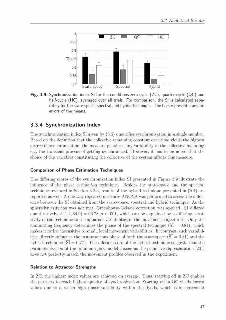
3.3 Analytical Results
0.7
0.75
0.8
0.85
0.9
0.95
1
ZC QC HC
SI
State-space Spectral Hybrid
Fig. 3.9: Synchronization index SI for the conditions zero-cycle (ZC), quarter-cycle (QC) andhalf-cycle (HC), averaged over all trials. For comparison, the SI is calculated sepa-rately for the state-space, spectral and hybrid technique. The bars represent standarderrors of the means.
3.3.4 Synchronization Index
The synchronization index SI given by (3.5) quantifies synchronization in a single number.
Based on the definition that the collective remaining constant over time yields the highest
degree of synchronization, the measure penalizes any variability of the collective including
e.g. the transient process of getting synchronized. However, it has to be noted that the
choice of the variables constituting the collective of the system affects this measure.
Comparison of Phase Estimation Techniques
The differing scores of the synchronization index SI presented in Figure 3.9 illustrate the
influence of the phase estimation technique. Besides the state-space and the spectral
technique reviewed in Section 3.2.3, results of the hybrid technique presented in [201] are
reported as well. A one-way repeated measures ANOVA was performed to assess the differ-
ence between the SI obtained from the state-space, spectral and hybrid technique. As the
sphericity criterion was not met, Greenhouse-Geisser correction was applied. SI differed
quantitatively, F (1.2, 34.9) = 66.78, p < .001, which can be explained by a differing sensi-
tivity of the technique to the apparent variabilities in the movement trajectories. Only the
dominating frequency determines the phase of the spectral technique (SI = 0.84), which
makes it rather insensitive to small, local movement variabilities. In contrast, such variabil-
ities directly influence the instantaneous phase of both the state-space (SI = 0.81) and the
hybrid technique (SI = 0.77). The inferior score of the hybrid technique suggests that the
parameterization of the minimum jerk model chosen as the primitive representation [201]
does not perfectly match the movement profiles observed in the experiment.
Relation to Attractor Strengths
In ZC, the highest index values are achieved on average. Thus, starting off in ZC enables
the partners to reach highest quality of synchronization. Starting off in QC yields lowest
values due to a rather high phase variability within the dyads, which is in agreement
47
3 Modeling of Human Movement Coordination
with the distribution in Figure 3.8b. Medium index values are attained in HC. Though
the resulting indexes show numerically similar trends within techniques, one-way repeated
measures ANOVAs with the within-subject factor condition (ZC, QC, HC) performed
for each technique did not reveal any significant differences between start off conditions,
all p > .05. If we interpret the synchronization index as an indication of strength of the
involved attractors, the attractor strengths of the in-phase and the anti-phase relation
can not be distinguished in the present goal-directed task. In contrast, research work
on interpersonal movement synchronization in purely rhythmic tasks provides evidence of
differing attractor strengths. The anti-phase attractor is usually weaker than the in-phase
attractor, or it even disappears completely [139, 150].
Remark 3.13 SI is calculated for whole trials including the transient process of synchro-
nization. If the effects of transients is reduced by calculating the SI for the second half of
the trials, qualitative results still show a similar trend.
3.4 Human-Human Synchronization Model
The dynamical systems approach is adopted in the following to describe movement synchro-
nization. Emerging coordination patterns are represented by the attractors of a dynamical
system. Thereby attractors denote the regions in the state-space to which the state tra-
jectories of the system are attracted. In particular, we treat the observed phenomena of
movement coordination in the goal-directed action task as a synchronization problem of
two coupled oscillators forming a coupled dynamical system, which is in line with existing
modeling approaches [53, 131, 152]. Therefore, we set up the appropriate model struc-
ture, which is then investigated with respect to its parameters, stability and predictive
properties. Finally, we present the quantitative results obtained from gray-box parameter
identification.
3.4.1 Model Structure
Coupled Phase Oscillators
First, we recall the general equations of motion of two limit cycle oscillators (3.2) that are
mutually coupled. Under the assumption that the coupling functions are weak and the
oscillatory dynamics are harmonic [87], the above equations can be reduced to a simpler
set written in terms of the phase angles θa/b of the oscillators as
θa = ωa + Ca(θb − θa)
θb = ωb + Cb(θa − θb), (3.11)
where ωa/b ∈ R are the natural frequencies of the oscillators and Ca/b : R → R the coupling
functions depending on the phase difference between the oscillators.
Remark 3.14 In the modeling approach, the phases θa/b(t) are assumed to be quasi-
harmonic. Harmonicity of phases is either fulfilled due to the harmonic nature of the
48
3.4 Human-Human Synchronization Model
movement trajectory, or it has to be ensured by appropriate phase transformations, e.g.
the marker-based technique presented in Section 4.2.4.
Extending the Kuramoto Model
Several candidates for the coupling functions Ca/b in (3.11) are found in literature in the
context of movement synchronization. One of them is the sinusoidal function proposed
by Rand et al. [131], which yields the model equations
θa = ωa +K sin(θb − θa) (3.12)
θb = ωb +K sin(θa − θb). (3.13)
It is known as the classical Kuramoto model established by Kuramoto [87], where K ∈ R is
the coupling gain between the oscillators. It is assumed to be isotropic for both oscillators.
The model structure of coupled Kuramoto oscillators is adopted for the following reasons:
• Despite its simplicity, the observed main effects of synchronization are replicated:
The natural frequencies refer to the agents’ individual frequency levels as an indi-
vidual behavior, whereas the additive non-linear coupling term allows weak synchro-
nization between the agents to emerge.
• Emerging synchronization is explained as an effect of co-adaptation via isotropic
bidirectional coupling. The directionality of the coupling characteristics would be
hard to identify from short-time bivariate data recorded during natural HHI, since
unsynchronized regimes have to be observed extensively [160].
• The goal-directedness of the task constrains the amplitudes of movements, thus
only the quasi-harmonic phase variables need to be considered. The two-degrees-
of-freedom model is expected to foster robust parameter identification from noisy
experimental data.
The phase difference dynamics of the oscillator pair are obtained by subtracting (3.13)
from (3.12). It can be compactly written as
Φ = ∆ω − 2K sinΦ, (3.14)
with Φ = θa − θb and the frequency detuning ∆ω ∈ R, defined as
∆ω = ωa − ωb. (3.15)
The analytical results in Section 3.3 show that the phase relation between the interacting
agents ends up predominantly either in in-phase (Φ = 0) or in anti-phase (Φ = π). There-
fore, we extend the phase difference dynamics (3.14) by two additional equilibrium points
per period of Φ, which yields the new differential equation of the phase difference
Φ = h(Φ) = ∆ω − 2K sin(2Φ). (3.16)
49
3 Modeling of Human Movement Coordination
The corresponding model equations read
θa = ωa +K sin[
2(
θb − θa)]
(3.17)
θb = ωb +K sin[
2(
θa − θb)]
, (3.18)
which is called the extended Kuramoto model in the following.
3.4.2 Stability Analysis
Next, the stability of the equilibrium points of the extended Kuramoto model is investi-
gated.
Proposition 3.1 The extended Kuramoto model (3.17) and (3.18) has equilibrium
points Φe, if and only if the parameter set (∆ω,K) satisfies the inequality
2 |K| − |∆ω| ≥ 0. (3.19)
Proof: To find the equilibrium points, we set Φ = 0 in (3.16), which yields
2K sin (2Φe) = ∆ω. (3.20)
Due to sin(·) ∈ [−1, 1], solutions of (3.20) only exist, if (3.19) holds. �
Graphically represented, the equilibrium points Φe are given by the points of intersection
of the curves 2K sin(2Φ) and ∆ω, see Figure 3.10.
In order to analyze the stability of the equilibrium points, we investigate whether per-
turbations grow or decay. Let η = Φ − Φe be a small perturbation away from Φe. First,
we derive a differential equation for η given by
η =d
dt(Φ− Φe) = Φ = h(Φe + η).
Using Taylor’s expansion and noting that h(Φe) = 0, one gets
η = ηh′(Φe) +O(η2),
where O(η2) gathers quadratically small terms in η. The gradient
h′(Φe) =d
dΦh|Φ=Φe = −4K cos(2Φe) (3.21)
denotes the attractor strength of Φe. If h′(Φe) 6= 0, the approximation can be written as
η = ηh′(Φe). (3.22)
It can be seen from (3.22) that the perturbation η grows exponentially, i.e. the equilib-
rium Φe is unstable, if h′(Φe) > 0. It decays, i.e. Φe is stable, if h
′(Φe) < 0. The stability
analysis can be visualized by investigating the dynamics of the vector field on the abscissa
50
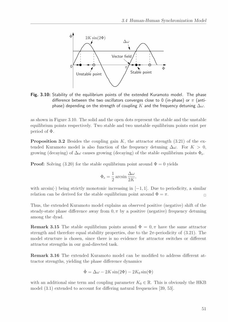
3.4 Human-Human Synchronization Model
2K sin(2Φ)∆ω
Unstable point
Vector field
Stable point
π0 Φ
Φ
Fig. 3.10: Stability of the equilibrium points of the extended Kuramoto model. The phasedifference between the two oscillators converges close to 0 (in-phase) or π (anti-phase) depending on the strength of coupling K and the frequency detuning ∆ω.
as shown in Figure 3.10. The solid and the open dots represent the stable and the unstable
equilibrium points respectively. Two stable and two unstable equilibrium points exist per
period of Φ.
Proposition 3.2 Besides the coupling gain K, the attractor strength (3.21) of the ex-
tended Kuramoto model is also function of the frequency detuning ∆ω. For K > 0,
growing (decaying) of ∆ω causes growing (decaying) of the stable equilibrium points Φe.
Proof: Solving (3.20) for the stable equilibrium point around Φ = 0 yields
Φe =1
2arcsin
∆ω
2K,
with arcsin(·) being strictly monotonic increasing in [−1, 1]. Due to periodicity, a similar
relation can be derived for the stable equilibrium point around Φ = π. �
Thus, the extended Kuramoto model explains an observed positive (negative) shift of the
steady-state phase difference away from 0, π by a positive (negative) frequency detuning
among the dyad.
Remark 3.15 The stable equilibrium points around Φ = 0, π have the same attractor
strength and therefore equal stability properties, due to the 2π-periodicity of (3.21). The
model structure is chosen, since there is no evidence for attractor switches or different
attractor strengths in our goal-directed task.
Remark 3.16 The extended Kuramoto model can be modified to address different at-
tractor strengths, yielding the phase difference dynamics
Φ = ∆ω − 2K sin(2Φ)− 2K0 sin(Φ)
with an additional sine term and coupling parameter K0 ∈ R. This is obviously the HKB
model (3.1) extended to account for differing natural frequencies [39, 53].
51
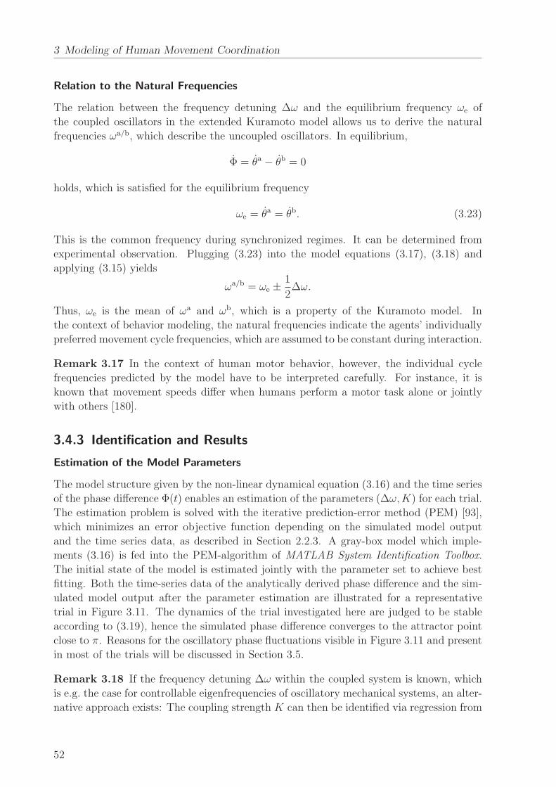
3 Modeling of Human Movement Coordination
Relation to the Natural Frequencies
The relation between the frequency detuning ∆ω and the equilibrium frequency ωe of
the coupled oscillators in the extended Kuramoto model allows us to derive the natural
frequencies ωa/b, which describe the uncoupled oscillators. In equilibrium,
Φ = θa − θb = 0
holds, which is satisfied for the equilibrium frequency
ωe = θa = θb. (3.23)
This is the common frequency during synchronized regimes. It can be determined from
experimental observation. Plugging (3.23) into the model equations (3.17), (3.18) and
applying (3.15) yields
ωa/b = ωe ±1
2∆ω.
Thus, ωe is the mean of ωa and ωb, which is a property of the Kuramoto model. In
the context of behavior modeling, the natural frequencies indicate the agents’ individually
preferred movement cycle frequencies, which are assumed to be constant during interaction.
Remark 3.17 In the context of human motor behavior, however, the individual cycle
frequencies predicted by the model have to be interpreted carefully. For instance, it is
known that movement speeds differ when humans perform a motor task alone or jointly
with others [180].
3.4.3 Identification and Results
Estimation of the Model Parameters
The model structure given by the non-linear dynamical equation (3.16) and the time series
of the phase difference Φ(t) enables an estimation of the parameters (∆ω,K) for each trial.
The estimation problem is solved with the iterative prediction-error method (PEM) [93],
which minimizes an error objective function depending on the simulated model output
and the time series data, as described in Section 2.2.3. A gray-box model which imple-
ments (3.16) is fed into the PEM-algorithm of MATLAB System Identification Toolbox.
The initial state of the model is estimated jointly with the parameter set to achieve best
fitting. Both the time-series data of the analytically derived phase difference and the sim-
ulated model output after the parameter estimation are illustrated for a representative
trial in Figure 3.11. The dynamics of the trial investigated here are judged to be stable
according to (3.19), hence the simulated phase difference converges to the attractor point
close to π. Reasons for the oscillatory phase fluctuations visible in Figure 3.11 and present
in most of the trials will be discussed in Section 3.5.
Remark 3.18 If the frequency detuning ∆ω within the coupled system is known, which
is e.g. the case for controllable eigenfrequencies of oscillatory mechanical systems, an alter-
native approach exists: The coupling strength K can then be identified via regression from
52
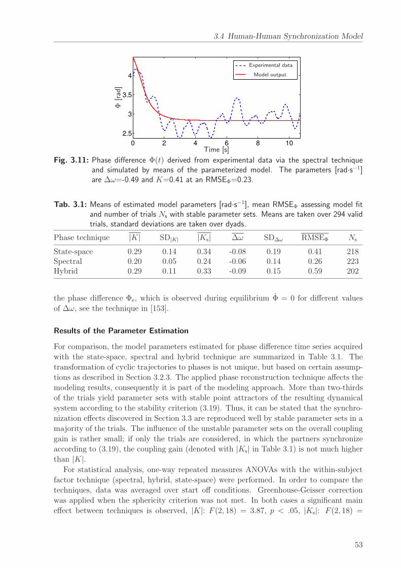
3.4 Human-Human Synchronization Model
0 2 4 6 8 10
2.5
3
3.5
4
Time [s]
Φ[rad]
Experimental data
Model output
Fig. 3.11: Phase difference Φ(t) derived from experimental data via the spectral techniqueand simulated by means of the parameterized model. The parameters [rad·s−1]are ∆ω=-0.49 and K=0.41 at an RMSEΦ=0.23.
Tab. 3.1: Means of estimated model parameters [rad·s−1], mean RMSEΦ assessing model fitand number of trials Ns with stable parameter sets. Means are taken over 294 validtrials, standard deviations are taken over dyads.
Phase technique |K| SD|K| |Ks| ∆ω SD∆ω RMSEΦ Ns
State-space 0.29 0.14 0.34 -0.08 0.19 0.41 218Spectral 0.20 0.05 0.24 -0.06 0.14 0.26 223Hybrid 0.29 0.11 0.33 -0.09 0.15 0.59 202
the phase difference Φe, which is observed during equilibrium Φ = 0 for different values
of ∆ω, see the technique in [153].
Results of the Parameter Estimation
For comparison, the model parameters estimated for phase difference time series acquired
with the state-space, spectral and hybrid technique are summarized in Table 3.1. The
transformation of cyclic trajectories to phases is not unique, but based on certain assump-
tions as described in Section 3.2.3. The applied phase reconstruction technique affects the
modeling results, consequently it is part of the modeling approach. More than two-thirds
of the trials yield parameter sets with stable point attractors of the resulting dynamical
system according to the stability criterion (3.19). Thus, it can be stated that the synchro-
nization effects discovered in Section 3.3 are reproduced well by stable parameter sets in a
majority of the trials. The influence of the unstable parameter sets on the overall coupling
gain is rather small; if only the trials are considered, in which the partners synchronize
according to (3.19), the coupling gain (denoted with |Ks| in Table 3.1) is not much higher
than |K|.For statistical analysis, one-way repeated measures ANOVAs with the within-subject
factor technique (spectral, hybrid, state-space) were performed. In order to compare the
techniques, data was averaged over start off conditions. Greenhouse-Geisser correction
was applied when the sphericity criterion was not met. In both cases a significant main
effect between techniques is observed, |K|: F (2, 18) = 3.87, p < .05, |Ks|: F (2, 18) =
53

3 Modeling of Human Movement Coordination
Tab. 3.2: Results of the trial-wise regression: R2 represents the percentage of the varianceexplained by the model, Nv is the number of valid trials included into analysis forthe respective condition, and Np<.001 lists the number of significant model fits.
Phase technique Condition Median R2 Nv Np<.001
State-space Zero-cycle 0.313 98 98Quarter-cycle 0.994 97 97Half-cycle 0.996 99 99
Spectral Zero-cycle 0.350 98 97Quarter-cycle 0.971 97 96Half-cycle 0.998 99 99
Hybrid Zero-cycle 0.223 98 98Quarter-cycle 0.904 97 97Half-cycle 0.995 99 99
3.88, p < .05. Contrasts show that the spectral technique results in the smallest coupling
gain on average compared to both the hybrid, |K|: F (1, 9) = 8.37, p < .05, |Ks|: F (1, 9) =6.09, p < .05, and the state-space technique |K|: F (1, 9) = 7.15, p < .05, |Ks|: F (1, 9) =7.50, p < .05, with the latter not being different from each other. This illustrates that
the commonly detected synchronization effects are explained by a non-zero coupling term,
though no instructions were given in the experiment, which would actively modulate the
interaction.
A mean ∆ω close to zero indicates a rather balanced frequency detuning over all dyads.
Here, no significant differences between the techniques are found, p > .6. The considerably
high SD ∆ω leads to the conclusion that the frequency detuning predicted by the model
is an individual parameter varying between dyads.
Evaluation of the Model Fit
For comparison of the root-mean-square error between model prediction and measure-
ment (RMSEΦ in Table 3.1) a one-way repeated measures ANOVA with the within-subject
factor technique (spectral, hybrid, state-space) was performed. DoF were corrected with
the Greenhouse-Geisser method. Highly significant differences between techniques are ob-
served, F (1.1, 9.7) = 28.37, p < .001. Best model fit is achieved by the combination of
the extended Kuramoto model and the spectral technique. It differs significantly from
the RMSEΦ obtained with the state-space technique, F (1, 9) = 167.47, p < .001, and the
hybrid technique, F (1, 9) = 38.53, p < .001. Furthermore, RMSEΦ is lower with the state-
space than with the hybrid technique, F (1, 9) = 11.20, p < .01. This is due to the filtering
property of the Hilbert transform, as the frequency at the maximum of the power spectrum
determines the instantaneous frequency and phase respectively. Both the state-space and
hybrid technique are applied without filtering and thus, yield a higher phase variability
than the spectral technique, which is not explained by the model.
Additionally, the goodness of fit achieved in combination with each of the three phase
estimation techniques is assessed with the R-squared metric (R2), which allows for an
54
3.5 Discussion
estimation of how much variance of the data (in %) is explained by the respective model.
The median values of the trial-wise R2 are summarized in Table 3.2. In order to find out
how often the variance of the data is explained above chance level, the significance of the
per-trial model fit is tested by calculating the F-ratio. Nearly all of the valid trials yield
significant fits, as reported in Table 3.2.
3.5 Discussion
Both the analytical results and the model identification provide evidence for and char-
acterize the emerging synchronization of movements. Treating human dyadic interaction
in a repetitive, goal-directed task as a synchronization problem with the phase difference
of coupled oscillators as the collective seems to be a valid approach. Its implications are
discussed in the following.
3.5.1 Interpretation of Results
In most of the trials, the participants fall into rhythmic patterns and synchronize as the
effect of a spontaneously emerging, joint behavioral goal, although precision is required
as individual goals for the partners. Special emphasis is put on the design of the task
paradigm due to the potential dependency of results on the task context. The experimental
setting is natural in the sense that it bears similarity to repetitive, goal-oriented action
tasks. People are not instructed to synchronize, but only get an instruction required for
the individual task performance, which allows natural interaction to emerge. Besides the
start off condition, no control variables are introduced that could artificially modulate the
flow of interaction. This should allow to interpret the results in the light of natural HHI.
As a result of the system identification, per-trial values of the parameter set (∆ω,K) are
found. Within our modeling approach, the parameters are assumed to be time-invariant
over the course of single experimental trials. The parameter sets averaged over trials can
be treated as behavioral features of the dyads. However, accidental as well as deliberate
parameter variations might be present due to both environmental influences and intrinsic
changes of the human behavior.
The frequency detuning ∆ω expresses shifts of the equilibrium points which attract
the collective. It can serve as a measure of discrepancy regarding the agents’ individu-
ally desired cycle frequency in the task. Furthermore, hypothetical natural frequencies of
the agents can be determined. Their meaning might extend to the self-organization of
leader and follower roles during movement coordination, which deserves, however, further
investigation in the light of role behavior among humans.
The coupling gain K quantifies a dyad’s weighing of two potentially competing goals:
Being precise to fulfill the instructed goal versus being synchronized with the partner as
an additional, voluntary goal. Non-zero mean values of K averaged over all trials indicate
emerging interactive behavior of the partners which leads to the observed patterns of syn-
chronization. The regression model employed by Schmidt et al. [153] to measure coupling
strength and the extended Kuramoto model proposed in this chapter are locally identical
due to the sinusoidal coupling, hence the resulting coupling from both task paradigms
55
3 Modeling of Human Movement Coordination
can be put into relation. The overall mean2 of 2 |K| (0.52 rad · s−1) in Table 3.1 is about
one-third of the mean value (1.70 rad · s−1) which is reported in [153] as the local model
coupling strength of intentional interpersonal coordination. Since in their experiments, the
participants were instructed to swing pendulums either in in-phase or anti-phase relation,
a coupling strength stronger than in our spontaneous setting is plausible.
Residuals after Modeling
The extended Kuramoto model predicts only the dominant component of the collective
dynamics via first-order non-linear dynamics. The median R2 under condition ZC is re-
markably low regardless of the technique. The measured phase difference remains constant
and close to the attractor Φ = 0 for most of the ZC trials, i.e. the dyad is initialized close
to equilibrium. Therefore, the explanatory power of the extended Kuramoto model in ZC
does not exceed much that of the pure mean value of the measured phase difference. Com-
pared to the considerably high R2 values obtained for the conditions QC and HC, this
emphasizes the need for extensive observations of transient behavior in non-equilibrium
regimes to gain meaningful model fits.
Spectral analysis of the residuals reveals oscillatory components at frequencies close to
the participants’ mean cycle frequency (0.73Hz averaged over all trials), cf. Figure 3.11.
This finding is in line with the observations made by [152] during the task of pendulum
swinging. The oscillations can be explained by the following reasons. First and foremost,
the observed phase fluctuations can be artifacts of the phase estimation. The instantaneous
phase of measured oscillatory time series such as human movement trajectories can be
uniquely determined only over cycles for a discrete marker event in the cycle, while the
evolution within cycles strongly depends on the reconstruction technique. Neither the
movement trajectories of the individuals are perfectly harmonic nor the phase estimation
techniques achieve perfectly harmonic phases due to individual variabilities. Thus, the
limit cycles appear in their state-space not perfectly circular but slightly distorted, see the
example in 3.2.3. Even if we would assume equally distorted limit cycles for both partners,
the phase difference Φ(t) would still oscillate with multiples of the cycle frequency, except
for the case Φ(t) = 0. In their note on coordination models, Fuchs and Kelso [39] show
that these phase fluctuations can be reproduced by the original HKB model comprised by
non-harmonic oscillators. Alternatively, this effect could be mitigated by linearizing phase
estimation techniques.
Potentially, the model residuals contain additional relevant information. The coupling
strength between the agents might not be constant over time but rather include a com-
ponent depending on the individual phase. This assumption is backed by the workspace
topology of the experimental task investigated here. Since simultaneous visual attention to
one’s own and the partner’s movements is easier when getting close to the target area and
the partner’s workspace respectively, it might effect the coupling strength. The integrative
role of the visual perception of relative phase is shown to affect the stability of coordination
in [187].
2Values of K have to be doubled for comparison, since here, K refers to the single agent’s unilateralcoupling.
56

3.5 Discussion
Influence of the Phase Estimation Technique
Different techniques on the calculation of instantaneous phases from experimental move-
ment data are evaluated in this chapter. Their performance is assessed by
• the synchronization index SI, which penalizes the phase variability.
• the RMSEΦ of the phase difference, which accounts for the residuals after model
identification.
Comparison of the synchronization index and the RMSE-based model fit yield similar
performance trends for the phase techniques. This similarity is explained by the following
fact: The proposed model structure replicates the dominant process of phase convergence
only, hence the model residuals directly reflect any additional variance of the collective.
Both the RMSEΦ and the SI are affected in the same way. Best performance results are
achieved when the phases are generated by the spectral technique. Though it is a powerful
tool when it comes to off-line analysis, the spectral technique is less suitable for on-line
application. A short-time implementation of the Hilbert transform would be required,
which comes at the cost of signal delay due to windowing. For movement tasks comprised
by quasi-harmonic action sequences, where a two-dimensional state-space can be defined
for embedding and the state variables can be constructed from measurement, the state-
space technique is a good alternative. It can be also deployed on-line. The conceptual idea
of the hybrid technique might be beneficially applied if the phase of more complex, non-
harmonic primitive sequences is to be estimated on-line and models explicitly formulated
in time exist.
3.5.2 Implications for the Design of Interactive Behavior
The composition of the individual (autonomous) and joint (collective) behavior defines the
DoF of the presented behavioral model. Each is influenced by a single model parameter
with an intuitive meaning:
• The autonomous oscillation renders an agent’s individual behavior in that it ensures
the urge and desired speed to proceed the action task. For the simple case of the
harmonic phase oscillator, it is fully described by the natural frequency. Here, the
phase represents the temporal distance to goal achievement, i.e. the completion of
the period.
• The coupling function renders the agent’s collective behavior, since it mediates the
agent’s urge to proceed depending on feedback from the partner’s action. For the
extended Kuramoto model, the characteristics and strength of this external forcing
is fully defined by the sinusoidal coupling as a function of the difference between the
own and the partner’s phase.
Only few requirements have to be met in order to embed the behavioral model into the
perception-action loop of robotic agents. In robotics, the phase oscillator is related to the
notion of central pattern generators (CPGs) in its simplest form. CPGs are utilized to dic-
tate the timing of continuous rhythmic motion, with or without environmental feedback.
57
3 Modeling of Human Movement Coordination
Their application reaches back to bio-inspired modeling approaches of animal locomo-
tion [18]. The phase evolution of the harmonic oscillator explicitly governs the timing of
actions, i.e. in the unforced cases it represent the time variable. Thus, any kind of action
generation scheme may be deployed provided that a formulation explicitly parameterized
in time exists. An example with relevance to goal-directed HRI is the minimum jerk
model [36], which replicates point-to-point movements of the human hand.
With regard to the informational coupling to the partner, the movement trajectory
relevant to synchronization needs to be acquired, which is technically facilitated through
visual tracking techniques. Perceptual processing delays should either be kept small or
compensated to enable the desired temporal coordination. Similarly, the transformation
of observed movements to the phase variable needs to be performed on-line. Since human
movements are assumed to be non-stationary, the times of period completion are a-priori
unknown. Therefore, phase estimation additionally requires predictions on the limit cycle.
The state-space technique handles quasi-harmonic movements as observed in the move-
ment task investigated above. However, joint action tasks such as the one investigated
in Chapter 4 usually involve more complex limit cycle representations, which make the
instantaneous phase estimation challenging. In this context, we will investigate an on-line
version of the marker-based technique in Section 4.2.4.
3.6 Conclusion and Open Issues
The analytical perspective towards the design of interactive behavior is pursued, and a
step-wise approach towards a behavioral model of human-human movement coordination
is presented. Synchronization is discovered to be an essential principle of human movement
coordination in the novel context of goal-directed action. Governed by a dynamical pro-
cess, human dyads mostly fall into in-phase as well as anti-phase relations. The emerging
relations are successfully replicated by the attractor dynamics of coupled phase oscillators
inspired by the Kuramoto model, which is defined by the evolution of its phases. The
proposed modeling concept fosters natural HHI and simultaneously facilitates the iden-
tification of the model parameters, which are the coupling strength and the frequency
detuning among the dyad. Stable attractors resulting from the identified model match
the movement relations observed in the experiment. The choice of the technique that
transforms the movement trajectories into instantaneous phases is shown to significantly
influence the model fit. Best fit is achieved by use of the spectral technique, which proves
well-suited for the off-line analysis of simple repetitive actions. Due to the two-layered
formulation of the coordination behavior in terms of the coupled phase dynamics and the
movement-to-phase transformations, the concept facilitates the modeling of interactive be-
havior even if dyads are performing heterogeneous action tasks. By means of the identified
model, interactive behavior of a robotic partner can be readily rendered on-line. Integrat-
ing the human behavioral model developed in this chapter, we will design and evaluate
interactive behavior for joint action coordination of human-robot dyads in line with the
synthetical perspective in Chapter 4.
Some interesting open issues remain concerning the endeavor of modeling human-human
movement coordination. First and foremost, the directionality of coupling within the
58
3.6 Conclusion and Open Issues
dyads established through the visual modality could be assessed. However, this endeavor
is challenging due to the noisy, short and bivariate time series data as obtained from the
proposed experimental design. Actively controlling the coupling modality is suggested
for the study design. Similarly, the potential dependency of the interpersonal coupling
strength on the partners’ visual foci or peripheral visual access respectively would be
worth an investigation. In goal-directed settings such as the paradigm presented here, the
determined coupling within dyads is supposed to reflect the individual weighing of the
individually required goal fulfillment vs. the spontaneous desire to jointly synchronize.
Particularly in the joint action context, the analysis of such kind of behavioral weighings
poses further interesting challenges.
59

4 Synchronization Behavior for Action
Coordination
Synchronization is a frequently observed phenomenon across different modalities and sit-
uations of interaction. In particular, the synchronization of movements is found to play
an essential role in the interactive behavior of humans. Due to its ubiquity in human
life, it is not surprising that evidence of interpersonal synchronization is provided in var-
ious laboratory tasks, that require jointly performed movements in shared workspaces,
see e.g. [138, 139, 151, 178]. We showed in Chapter 3, that spontaneously emerging co-
ordination patterns within human dyads also during goal-directed movement tasks are
explained well by coupled dynamical processes of synchronization. This coordination be-
havior is even sustained, if an obstacle is placed unilaterally in the workspace such, that
the movement trajectories become incongruent [198]. Studies targeting the social aspects
of synchronization highlight that falling into synchrony with partners enhances perceptual
sensitivity toward each other, fosters cooperative abilities [177] and leads to the attribu-
tion of more positive characteristics to the interaction partner [107]. These works give rise
to the hypothesis, that bidirectional action coordination with synchronization as its key
concept is a promising way to increase the social competence of robots when interacting
with humans [100].
Inspired by the appealing prospect to enrich the interaction repertoire of robots, this
chapter addresses the challenge of designing interactive behavior for artificial agents that
engage in repetitive joint action tasks. These tasks involve actions performed by two or
more individuals towards a shared goal in a common social setting, inducing action coordi-
nation in space and time [158]. Our goal is to develop enhanced interaction capabilities for
robotic agents, which promote their social compatibility and support collision avoidance
by increasing their predictability. Based on synchronization theory of coupled dynamical
systems [126] and focusing on joint action coordination on a continuous time scale, we
present a synchronization concept for repetitive, goal-directed movements composed by
multiple primitives. In particular, limit cycle representations are found for the joint action
task, that are segmented into sequences of primitives. Those can be mixed continuous and
discrete, making the proposed concept applicable to a wide range of repetitive action tasks.
Innovative is the synergetic integration of both the analytical and synthetical design per-
spective: Characteristics of human synchronization found in Chapter 3 are complemented
by novel, enhanced synchronization modes within pairs of limit cycles, considering both
continuous phases and discrete events from a unifying point of view. In line with the
behavioral dynamics approach [149, 185], we design a dynamical process to synchronize
the derived modes. Movement generation is addressed as well, in order to enable a robotic
agent equipped with synchronization behavior to engage in repetitive joint action tasks.
The presented experimental study employing a full-sized, anthropomorphic robot serves
not only as proof of concept. It also defines a versatile testbed for the investigation of
61
4 Synchronization Behavior for Action Coordination
human-robot action coordination in realistic settings.
This chapter is organized as follows: In Section 4.1 findings on human synchroniza-
tion behavior, related approaches in robotics as well as applications of synchronization
methods in human-computer and human-robot interaction are reviewed. Starting with a
representation of the task and related definitions, we develop enhanced synchronization
modes, the corresponding entrainment processes and the transformations between move-
ments and phase in Section 4.2. Following the synthetical design perspective, in Section 4.3
synchronization behavior is implemented and a human-robot synchronization experiment
is designed. The detailed assessment and evaluation of the implemented synchronization
behavior is reported in Section 4.4. After the discussion of the results and insights in the
context of human-robot joint action and from the design perspective in Section 4.5, we
sum up and draw the conclusions in Section 4.6.
4.1 Background
Different aspects are related to the design of synchronization behavior from an interdis-
ciplinary point of view. First, the background and results on continuous movement syn-
chronization of human dyads presented in Chapter 3 are complemented by inspiring find-
ings from research on human sensorimotor synchronization. Second, robotic applications
implementing limit cycle systems are reviewed. Finally, we discuss works investigating
human-machine movement synchronization in various application scenarios.
4.1.1 Human Sensorimotor Synchronization
The intended synchronization of human rhythmic movements with respect to purely dis-
crete, periodic stimuli such as auditory metronome beats is often called sensorimotor syn-
chronization (SMS). It is reproduced well by linear models of asynchrony correction based
on variants of the Wing-Kristofferson model [188], see Repp [135], Repp and Su [137] for
an exhaustive review. This class of simplified, linear models of phase and period correction
assumes one sequential update per period, i.e. at the stimulus event. It is well-suited to
explain perceptual and motor variabilities from an information-processing, cognitive point
of view. Contrasting the aforementioned linear error correction with the dynamical system
framework introduced in Section 3.1.2, it can be concluded that both modeling frameworks
are not exclusively competing for the same phenomenon, but rather account for different
synchronization processes present in different kinds of tasks [171]. When considering tasks
and the available sensory feedback modalities that feature mixed discrete and continuous
aspects, it is recently debated whether hybrid incarnations unifying both model classes
may exist [136] or not [25], stating exclusivity of the modeled processes. Irrespective of
the underlying process, it is found that the availability of discrete perceptual information
such as distinguishable events during continuous movement provides anchoring points for
time keeping with a stimulus and, thus, fosters human SMS [164]. Notably, in a recently
investigated dyadic version of the finger tapping task, humans adjust their pacing on a fast
time scale toward each other, thus improving coordination by mutually coupled SMS [79].
62
4.1 Background
4.1.2 Limit Cycle Systems in Robotics
Models creating rhythmic movement based on self-sustained oscillators and thus, limit cycle
systems are often called central pattern generators (CPGs) in robotics. The integration
of sensory feedback is considered not necessary, yet it is often introduced to modulate
CPG-based movements in response to the environment. In [127], the entrainment of robot
drumming is modeled by a CPG based on a phase oscillator, which is connected to a non-
linear dynamical system transforming the CPG signals into motion. While phase locking is
achieved regarding the beats, linear interpolation is applied to obtain a continuous phase
from the beat events. An extension of the CPG approach by reconfigurable dynamical
systems is proposed in [24] to generate movements in multiple DoF. While switching is
achieved between mixed discrete and rhythmic movements that are weakly constrained, the
formulation seems to lack an intuitive specification of goal-directed tasks. In the same line
of research, a unifying concept of encoding periodic movements based on dynamical systems
which are capable of feedback modulation is presented in [41] and developed further in [125].
Adaptive frequency oscillators are proposed to on-line tune and extract the frequency and
phase components of the trajectory. Results obtained from non-stationary trajectories,
however, show a rather slow rate of convergence. Limit cycles used in CPGs offer robustness
of motor behavior against perturbations, while also reducing the input dimensionality, i.e.
few driving signals suffice to modulate the output behavior based on sensory feedback. An
open issue is the missing methodology allowing a systematic, application-oriented design
of CPGs. For a profound review of CPGs focusing on biological and robotic locomotion
research, the reader is referred to [66]. An excellent review on design and classification of
different limit cycle systems with a focus on robotic applications is provided in [15].
4.1.3 Human-Machine Movement Synchronization
Some works investigate the synchronization of rhythmic movements between humans and
machines. Mutual entrainment is achieved by providing the human with visual or acoustic
stimuli as real-time feedback to his movements. For example, a virtual walking assistant
generating an acoustically-rendered pace is proposed to provide walking support to im-
paired persons [109]. Regular gait patterns are stimulated by a Kuramoto phase oscillator,
while the natural frequency is modulated to enforce a target phase difference. The contin-
uous phase dynamics is updated by discrete feedback obtained from the footstep events.
Virtual partner interaction (VPI) is introduced by Kelso et al. [74] to systematically study
human-machine coordination. In a proof-of-concept implementation, the coordination of
finger movements between a human and a visually-rendered, virtual agent driven by the
HKB model [53] is explored under different coupling conditions.
Few works address the mutual entrainment of rhythmic movements between human and
robotic agents. Rope turning in cooperation with a human is investigated in [99] and later
in [77] as an example of physically coupled, rhythmic entrainment. The robot manipulator
is controlled to keep a certain phase relation between the sensed force and the turning
frequency of the rope estimated by a classical phase-locked loop (PLL) [64]. Similarly,
the idea of human-robot movement synchronization through a PLL is pursued in [174].
Wavelet transformation and Fourier series approximation extract and replicate rhythmic
63
4 Synchronization Behavior for Action Coordination
movements of an a priori selected target frequency component. Demonstrated movements
are imitated synchronously, yet the dynamics of synchronization are not considered ex-
plicitly. Both human-robot handshaking [72] and physical assistance for rhythmic knee
movements [192] are realized by a model based on the Matsuoka neural oscillator [102].
This kind of synchronization-based control is proposed to foster purely rhythmic inter-
action with the human relying on torque feedback. Considering the same tasks, [147]
implicitly achieve synchronization by employing an on-line polynomial design method of
the attractor dynamics. This method originally proposed by Okada et al. [114] creates an
attractor basin in the vicinity of a motion trajectory in state space, and thus allows to
encode rhythmic movement trajectories.
All of the works above employ limit cycle systems to model interactive behavior. They
are focused on fundamental research of human synchronization behavior and in the robotics
domain, on the application of movement synchronization in experimental tasks that are
mostly restricted to purely rhythmic trajectories. To the author’s best knowledge, none
of the existing works, except the author’s previous [196, 201], analyze and model synchro-
nization of goal-directed movement tasks with application to human-robot dyads.
4.2 Design of Synchronization Behavior
Applying synchronization theory of limit cycle systems and inspired by human behavioral
principles, synchronization behavior is synthesized with application to repetitive joint ac-
tion tasks. Descriptions of possible synchronization modes are derived, and a unified
synchronization process is developed.
4.2.1 Representation of Repetitive Joint Action
This section provides the formal representations and definitions that are utilized in this
chapter to characterize the joint action task as well as the behavioral goal of movement
synchronization. Here, the notion of joint action originated from cognitive psychology [158]
is extended to the interaction of robotic agents as well.
Definition 4.1 (Individual Task) Each agent’s part of the joint action task is called
the agent’s individual task. It is represented by the state trajectory ξ(t), i.e. the evolution
of the vector of relevant states ξ ∈ Rn over time t.
Remark 4.1 The state vector can be composed by the configuration of the agent’s limbs,
his hand (effector) position, or any other coordinates that provide a minimal description
of the movements associated with the individual task.
Remark 4.2 A certain set of states is considered suitable if the information conveyed
through the chosen description allows to explain and model the synchronization behavior
of the agents.
The proposed concept of movement synchronization exploits the repetitive aspect of the
individual tasks. Therefore, the state trajectories are required to fulfill the conditions to
be treated as cyclic representations.
64
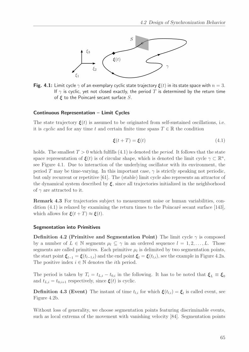
4.2 Design of Synchronization Behavior
ξ1
ξ2
ξ3
ξ(t)
γ
S
Fig. 4.1: Limit cycle γ of an exemplary cyclic state trajectory ξ(t) in its state space with n = 3.If γ is cyclic, yet not closed exactly, the period T is determined by the return timeof ξ to the Poincare secant surface S.
Continuous Representation – Limit Cycles
The state trajectory ξ(t) is assumed to be originated from self-sustained oscillations, i.e.
it is cyclic and for any time t and certain finite time spans T ∈ R the condition
ξ(t+ T ) = ξ(t) (4.1)
holds. The smallest T > 0 which fulfills (4.1) is denoted the period. It follows that the state
space representation of ξ(t) is of circular shape, which is denoted the limit cycle γ ⊂ Rn,
see Figure 4.1. Due to interaction of the underlying oscillator with its environment, the
period T may be time-varying. In this important case, γ is strictly speaking not periodic,
but only recurrent or repetitive [61]. The (stable) limit cycle also represents an attractor of
the dynamical system described by ξ, since all trajectories initialized in the neighborhood
of γ are attracted to it.
Remark 4.3 For trajectories subject to measurement noise or human variabilities, con-
dition (4.1) is relaxed by examining the return times to the Poincare secant surface [143],
which allows for ξ(t+ T ) ≈ ξ(t).
Segmentation into Primitives
Definition 4.2 (Primitive and Segmentation Point) The limit cycle γ is composed
by a number of L ∈ N segments µl ⊆ γ in an ordered sequence l = 1, 2, . . . , L. Those
segments are called primitives. Each primitive µl is delimited by two segmentation points,
the start point ξl−1 = ξ(tl−1,i) and the end point ξl = ξ(tl,i), see the example in Figure 4.2a.
The positive index i ∈ N denotes the ith period.
The period is taken by Ti = tL,i − t0,i in the following. It has to be noted that ξL ≡ ξ0
and tL,i = t0,i+1 respectively, since ξ(t) is cyclic.
Definition 4.3 (Event) The instant of time tl,i for which ξ(tl,i) = ξl is called event, see
Figure 4.2b.
Without loss of generality, we choose segmentation points featuring discriminable events,
such as local extrema of the movement with vanishing velocity [84]. Segmentation points
65
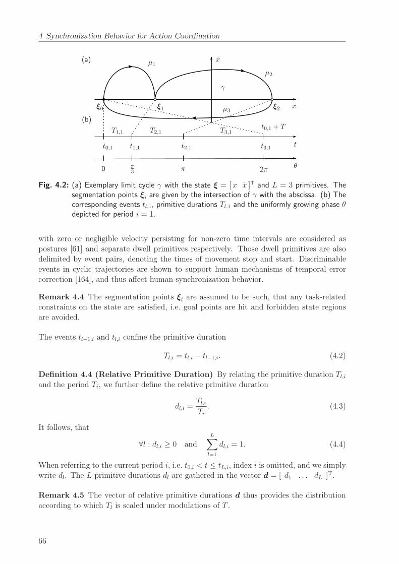
4 Synchronization Behavior for Action Coordination
(a)
(b)
x
x
t
θ
µ1
µ2
µ3
γ
ξ0 ξ1 ξ2
t0,1 t1,1 t2,1 t3,1
T1,1 T2,1 T3,1t0,1 + T
0 π3 π 2π
Fig. 4.2: (a) Exemplary limit cycle γ with the state ξ = [x x ]T and L = 3 primitives. Thesegmentation points ξi are given by the intersection of γ with the abscissa. (b) Thecorresponding events tl,1, primitive durations Tl,1 and the uniformly growing phase θdepicted for period i = 1.
with zero or negligible velocity persisting for non-zero time intervals are considered as
postures [61] and separate dwell primitives respectively. Those dwell primitives are also
delimited by event pairs, denoting the times of movement stop and start. Discriminable
events in cyclic trajectories are shown to support human mechanisms of temporal error
correction [164], and thus affect human synchronization behavior.
Remark 4.4 The segmentation points ξl are assumed to be such, that any task-related
constraints on the state are satisfied, i.e. goal points are hit and forbidden state regions
are avoided.
The events tl−1,i and tl,i confine the primitive duration
Tl,i = tl,i − tl−1,i. (4.2)
Definition 4.4 (Relative Primitive Duration) By relating the primitive duration Tl,iand the period Ti, we further define the relative primitive duration
dl,i =Tl,i
Ti. (4.3)
It follows, that
∀l : dl,i ≥ 0 andL∑
l=1
dl,i = 1. (4.4)
When referring to the current period i, i.e. t0,i < t ≤ tL,i, index i is omitted, and we simply
write dl. The L primitive durations dl are gathered in the vector d = [ d1 . . . dL ]T.
Remark 4.5 The vector of relative primitive durations d thus provides the distribution
according to which Tl is scaled under modulations of T .
66
4.2 Design of Synchronization Behavior
Phase-Amplitudes Decomposition
Through coordinate transformation, a limit cycle γ with state ξ ∈ Rn may be re-
parameterized by the one-dimensional variable θ that is called the phase and describes
the motion on γ, and the (n− 1)-dimensional vector of amplitudes that describe motions
transverse to γ. Phase and amplitudes are differentiated by their stability properties:
The phase is neither stable nor unstable, whereas the amplitudes are stable coordinates.
Consequently, after a perturbation of the state away from the limit cycle, we observe:
• The amplitudes relax back to the limit cycle.
• The phase remains neutrally, and thus, is easy to adjust.
The phase transformation is not unique. Different decompositions can be found for a
certain limit cycle [40]. In this work, we assume the amplitudes to be constrained by
the modeled action tasks. Consequently, only the phase is considered to be governed by
synchronization.
Definition 4.5 (Phase) Among all possible transformations, we choose the phase ob-
tained from the harmonic phase oscillator, which is one of the simplest oscillator models.
Its unperturbed oscillations evolve at constant phase velocity θ = ω, with positive ω ∈ R+
denoting the natural frequency. Accordingly, its phase trajectory is defined
θ(t) = ωt+ θ0, (4.5)
which is growing uniformly in time with some initial phase θ0. By setting
ω =2π
T, (4.6)
we further define the phase to be angular and 2π-periodic, evaluating
θ(iT ) = 2πi+ θ0, (4.7)
with index i counting periods.
Furthermore, the phase θ(t) needs to be uniquely related to a location of the state ξ(t)
on γ. Therefore, the instant of time of the state hitting the secant surface as depicted in
Figure 4.1 is denoted by the event t0,i. We deliberately choose θ0 such, that θ(t0,1) = 0 is
anchored to the point ξ(t0,1) = ξ0 marking the event t0,1. The phase of a stationary limit
cycle with constant period T is then readily given by (4.5). The important case of non-
stationary limit-cycles with a priori unknown period T (t) is addressed by the instantaneous
version of the marker-based technique presented later in this chapter.
Joint Behavioral Goal as Synchronization Problem
Agent a/b’s individual task is represented by the limit cycle γa/b and assumed to be
originated from self-sustained oscillations, which allows us to apply the theory of limit
cycle oscillators. In order to describe the motion of the state on the limit cycle, the notion
of phase is introduced and the harmonic phase is adopted.
67
4 Synchronization Behavior for Action Coordination
Remark 4.6 The transformation into phase and amplitudes can be understood as a de-
composition of the task into one DoF available for voluntary synchronization, i.e. the
phase variable, and the remaining DoF necessarily complying with the task goals, i.e. the
amplitude vector.
The joint behavioral goal is now treated as a synchronization problem by relating the
phases θa/b and the events ta/b
la/b,ia/bof limit cycles pairs to each other in time. In addition
to phase synchronization according to Definition 3.1, the quasi-simultaneous appearance
of event pairs is considered, which is known as event synchronization [129].
Definition 4.6 (Event Synchronization) Let tl,i denote the time of the lth event in
the ith period of γ. Then the event pair denoted by the tuple (tala , tblb) shows event syn-
chronization, if the events keep the temporal relation
∣
∣tala,ia − tblb,ia+m
∣
∣ < ∆t ∀ia, (4.8)
with some time span ∆t and the period offset m ∈ N.
Choosing m = const. ensures to test for event synchronization of order 1:1. The choice
of ∆t is considered as problem dependent. To avoid ambiguities, a reasonable upper bound
is given by
∆t ≤ 1
2minia,ib
{
T ala,ia , T
ala+1,ia, T
blb,ib , T
blb+1,ib
}
, (4.9)
which denotes half the minimum primitive duration or half the minimum inter-event dis-
tance respectively in the neighborhood of the considered pair(
tala , tblb
)
.
Remark 4.7 Definition 4.6 implies phase synchronization, since the time lag and, thus,
the phase difference between the considered events is bounded. Event synchronization
depending on the definition of relevant events provides a problem-specific characterization
of the temporal organization of limit cycle pairs.
4.2.2 Synchronization Modes
After analyzing the common modes of the synchronization between quasi-harmonic trajec-
tories, which are usually relevant for purely rhythmic movement tasks, we will broaden the
repertoire of potential synchronization modes between limit cycles, that feature multiple
primitives and events.
Modes between Harmonic Limit Cycles
Movement synchronization within human dyads is mainly investigated in task paradigms
that require purely rhythmic movements such as finger tapping, and leg or pendulum swing-
ing. These tasks are usually described by one-dimensional motion trajectories, resulting
in the state ξ ∈ R2 embedded in a position-velocity state space. Typically, each period
of the trajectory is composed by two nearly equal and sinusoidal half-periods, allowing to
characterize the oscillation as harmonic. Following Definition 4.2 and 4.3, the limit cycle γ
of the state trajectory ξ(t) is segmented into L = 2 primitives µl ⊂ γ, l = 1, 2, which are
68
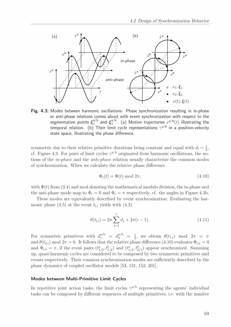
4.2 Design of Synchronization Behavior
(a) (b)
t xa
xa
xa
xa xa
xa
xb
xb xb
x(t), ξ(t)
x1, ξ1
x2, ξ2
in-phase
anti-phase
Fig. 4.3: Modes between harmonic oscillations: Phase synchronization resulting in in-phaseor anti-phase relations comes about with event synchronization with respect to thesegmentation points ξ
a/b1 and ξ
a/b2 . (a) Motion trajectories xa/b(t) illustrating the
temporal relation. (b) Their limit cycle representations γa/b in a position-velocitystate space, illustrating the phase difference.
symmetric due to their relative primitive durations being constant and equal with dl =12,
cf. Figure 4.3. For pairs of limit cycles γa/b originated from harmonic oscillations, the no-
tions of the in-phase and the anti-phase relation usually characterize the common modes
of synchronization. When we calculate the relative phase difference
Φr(t) = Φ(t) mod 2π, (4.10)
with Φ(t) from (3.4) and mod denoting the mathematical modulo division, the in-phase and
the anti-phase mode map to Φr = 0 and Φr = π respectively, cf. the angles in Figure 4.3b.
These modes are equivalently described by event synchronization: Evaluating the har-
monic phase (4.5) at the event tl,i yields with (4.3)
θ(tl,i) = 2πl
∑
j=1
dj + 2π(i− 1). (4.11)
For symmetric primitives with da/b1 = d
a/b2 = 1
2, we obtain θ(t1,i) mod 2π = π
and θ(t2,i) mod 2π = 0. It follows that the relative phase difference (4.10) evaluates Φr,e = 0
and Φr,e = π, if the event pairs (ta1/2, tb1/2) and (ta1/2, t
b2/1) appear synchronized. Summing
up, quasi-harmonic cycles are considered to be composed by two symmetric primitives and
events respectively. Their common synchronization modes are sufficiently described by the
phase dynamics of coupled oscillator models [53, 131, 152, 201].
Modes between Multi-Primitive Limit Cycles
In repetitive joint action tasks, the limit cycles γa/b representing the agents’ individual
tasks can be composed by different sequences of multiple primitives, i.e. with the number
69
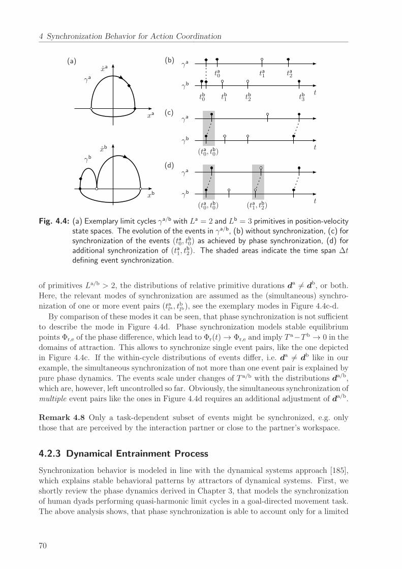
4 Synchronization Behavior for Action Coordination
(a) (b)
(c)
(d)
t
t
t
ta0 ta1 ta2
γa
γa
γa
γa
xa
xa
xb
xb
γb
γb
γb
γb
tb0 tb1 tb2 tb3
(ta0, tb0)
(ta0, tb0)
(ta1, tb2)
Fig. 4.4: (a) Exemplary limit cycles γa/b with La = 2 and Lb = 3 primitives in position-velocitystate spaces. The evolution of the events in γa/b, (b) without synchronization, (c) forsynchronization of the events (ta0, t
b0) as achieved by phase synchronization, (d) for
additional synchronization of (ta1, tb2). The shaded areas indicate the time span ∆t
defining event synchronization.
of primitives La/b > 2, the distributions of relative primitive durations da 6= db, or both.
Here, the relevant modes of synchronization are assumed as the (simultaneous) synchro-
nization of one or more event pairs (tala, tblb), see the exemplary modes in Figure 4.4c-d.
By comparison of these modes it can be seen, that phase synchronization is not sufficient
to describe the mode in Figure 4.4d. Phase synchronization models stable equilibrium
points Φr,e of the phase difference, which lead to Φr(t) → Φr,e and imply T a−T b → 0 in the
domains of attraction. This allows to synchronize single event pairs, like the one depicted
in Figure 4.4c. If the within-cycle distributions of events differ, i.e. da 6= db like in our
example, the simultaneous synchronization of not more than one event pair is explained by
pure phase dynamics. The events scale under changes of T a/b with the distributions da/b,
which are, however, left uncontrolled so far. Obviously, the simultaneous synchronization of
multiple event pairs like the ones in Figure 4.4d requires an additional adjustment of da/b.
Remark 4.8 Only a task-dependent subset of events might be synchronized, e.g. only
those that are perceived by the interaction partner or close to the partner’s workspace.
4.2.3 Dynamical Entrainment Process
Synchronization behavior is modeled in line with the dynamical systems approach [185],
which explains stable behavioral patterns by attractors of dynamical systems. First, we
shortly review the phase dynamics derived in Chapter 3, that models the synchronization
of human dyads performing quasi-harmonic limit cycles in a goal-directed movement task.
The above analysis shows, that phase synchronization is able to account only for a limited
70
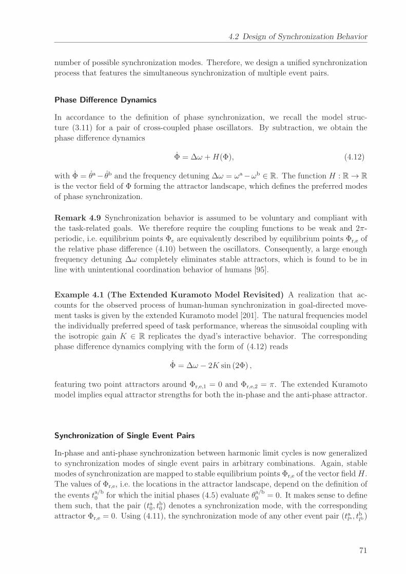
4.2 Design of Synchronization Behavior
number of possible synchronization modes. Therefore, we design a unified synchronization
process that features the simultaneous synchronization of multiple event pairs.
Phase Difference Dynamics
In accordance to the definition of phase synchronization, we recall the model struc-
ture (3.11) for a pair of cross-coupled phase oscillators. By subtraction, we obtain the
phase difference dynamics
Φ = ∆ω +H(Φ), (4.12)
with Φ = θa− θb and the frequency detuning ∆ω = ωa−ωb ∈ R. The function H : R → R
is the vector field of Φ forming the attractor landscape, which defines the preferred modes
of phase synchronization.
Remark 4.9 Synchronization behavior is assumed to be voluntary and compliant with
the task-related goals. We therefore require the coupling functions to be weak and 2π-
periodic, i.e. equilibrium points Φe are equivalently described by equilibrium points Φr,e of
the relative phase difference (4.10) between the oscillators. Consequently, a large enough
frequency detuning ∆ω completely eliminates stable attractors, which is found to be in
line with unintentional coordination behavior of humans [95].
Example 4.1 (The Extended Kuramoto Model Revisited) A realization that ac-
counts for the observed process of human-human synchronization in goal-directed move-
ment tasks is given by the extended Kuramoto model [201]. The natural frequencies model
the individually preferred speed of task performance, whereas the sinusoidal coupling with
the isotropic gain K ∈ R replicates the dyad’s interactive behavior. The corresponding
phase difference dynamics complying with the form of (4.12) reads
Φ = ∆ω − 2K sin (2Φ) ,
featuring two point attractors around Φr,e,1 = 0 and Φr,e,2 = π. The extended Kuramoto
model implies equal attractor strengths for both the in-phase and the anti-phase attractor.
Synchronization of Single Event Pairs
In-phase and anti-phase synchronization between harmonic limit cycles is now generalized
to synchronization modes of single event pairs in arbitrary combinations. Again, stable
modes of synchronization are mapped to stable equilibrium points Φr,e of the vector fieldH.
The values of Φr,e, i.e. the locations in the attractor landscape, depend on the definition of
the events ta/b0 for which the initial phases (4.5) evaluate θ
a/b0 = 0. It makes sense to define
them such, that the pair (ta0, tb0) denotes a synchronization mode, with the corresponding
attractor Φr,e = 0. Using (4.11), the synchronization mode of any other event pair (tala, tblb)
71
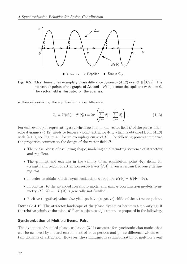
4 Synchronization Behavior for Action Coordination
replacements
Φ
Φ
∆ω
0 π 2π
−H(Φ)
Attractor Repeller Stable Φr,e
Fig. 4.5: R.h.s. terms of an exemplary phase difference dynamics (4.12) over Φ ∈ [0, 2π]. Theintersection points of the graphs of ∆ω and −H(Φ) denote the equilibria with Φ = 0.The vector field is illustrated on the abscissa.
is then expressed by the equilibrium phase difference
Φe = θa(tala)− θb(tblb) = 2π
la∑
j=1
daj −lb∑
j=1
dbj
. (4.13)
For each event pair representing a synchronized mode, the vector fieldH of the phase differ-
ence dynamics (4.12) needs to feature a point attractor Φr,e, which is obtained from (4.13)
with (4.10), see Figure 4.5 for an exemplary curve of H. The following points summarize
the properties common to the design of the vector field H:
• The phase plot is of oscillating shape, modeling an alternating sequence of attractors
and repellers.
• The gradient and extrema in the vicinity of an equilibrium point Φr,e define its
strength and region of attraction respectively [201], given a certain frequency detun-
ing ∆ω.
• In order to obtain relative synchronization, we require H(Φ) = H(Φ + 2π).
• In contrast to the extended Kuramoto model and similar coordination models, sym-
metry H(−Φ) = −H(Φ) is generally not fulfilled.
• Positive (negative) values ∆ω yield positive (negative) shifts of the attractor points.
Remark 4.10 The attractor landscape of the phase dynamics becomes time-varying, if
the relative primitive durations da/b are subject to adjustment, as proposed in the following.
Synchronization of Multiple Events Pairs
The dynamics of coupled phase oscillators (3.11) accounts for synchronization modes that
can be achieved by mutual entrainment of both periods and phase difference within cer-
tain domains of attraction. However, the simultaneous synchronization of multiple event
72
4.2 Design of Synchronization Behavior
(a) (b)
ta0
ta1
tb0
tb1
tb1
tb2
da1
da2
db1
db2
db3
T a/b
Φ(ta0, t
b0)
(ta1, tb2)
θa/b
da/b
Fig. 4.6: Circular illustration of the synchronization problem between the exemplary limit cy-cles γa (inner circle) and γb (outer circle) introduced in Figure 4.4. (a) The DoFavailable for synchronization: The periods T a/b and the phase difference Φ are bothgoverned by the process (3.11). Additionally, the relative primitive durations da/b aregoverned by the process (4.14). (b) Perfect synchronization of the event pairs (ta0, t
b0)
and (ta1, tb2), leading to coincident circles and events.
pairs remains generally unexplained, as shown previously. Therefore, the relative primitive
durations da/b are proposed as additional DoF, governed by the cross-coupled first-order
dynamics of the form
da= Da(da,db)
db= Db(db,da), (4.14)
with the vector fields Da/b : RLa ×RLb → R
La/band da/b subject to the condition (4.4). In
Figure 4.6, the DoF of the overall synchronization process are illustrated for the exemplary
mode in Figure 4.4d, which is defined for two event pairs.
Remark 4.11 Synchronization modes that would require to accommodate large differ-
ences between the components of da/b or between combinations thereof might be infeasible,
e.g. due to velocity constraints related to the agents’ capabilities or their individual tasks.
Similar to the range of frequency detuning ∆ω in (4.12) limiting stable phase synchroniza-
tion, the process (4.14) is therefore assumed to be subject to locally bounded regions of
attraction.
Remark 4.12 Normalization is preserved by adjusting the components of da/b such that
La/b∑
l=1
da/bl = 0, (4.15)
which is the derivative of the normalization constraint in (4.4).
73
4 Synchronization Behavior for Action Coordination
Example 4.2 (Entrainment of Relative Primitive Durations) In the following, we
outline a possible realization of the process (4.14), that features the mode illustrated
in Figure 4.6b. In this mode, the event pairs (ta0, tb0) and (ta1, t
b2) appear synchronized
simultaneously. The former is readily synchronized by the phase difference dynamics (4.12)
employing the stable equilibrium point Φr,e = 0. In order to additionally synchronize the
latter, we design the entrainment of da = [ da1 da2 ]T to follow the dynamics
da1 = −da2 (4.16)
da2 = Kd sinπ(
db3,s − da2)
da2,u − da2,l. (4.17)
By (4.16), normalization is preserved. The positive gain Kd ∈ R+ in (4.17) enforces the
solution da2 = db3,s to be stable, saturated by
db3,s =
da2,l, if db3 < da2,l
db3 , if da2,l ≤ db3 ≤ da2,u
da2,u, otherwise.
The positive thresholds da2,l and da2,u define the lower and upper bound on the entrainment
of da2. Assuming isotropic coupling between the agents, the entrainment of db is designed
analogously.
4.2.4 From Movement to Phase
The previously developed synchronization process governs the phase variables θa/b(t) as
well as the relative primitive durations da/b(t). Since we target the integration of the
synchronization behavior in the perception-action loop of robotic agents, the acquired
movement trajectories need to be transformed on-line into these process variables. The
problem considered first is to determine the partner’s phase instantaneously, based on
event predictions.
Marker-Based Technique
A novel, on-line version of the marker-based technique is proposed here. The marker tech-
nique is based on linear phase interpolation between a single marker event per period [143].
However, the desired phase variable is required to instantaneously reflect changes of the
period here. Given a prediction of the event t0,i+1(t) = tL,i(t) denoting the time of com-
pletion of the current period i, for time t ∈ [t0,i, t0,i+1(t)) a phase estimate θ(t) is proposed
as the solution of
ω(t) =˙θ(t) =
2πi− θ(t)
t0,i+1(t)− t, with θ(t0,i) = 2π(i− 1). (4.18)
The instantaneous frequency or phase velocity (4.18) is given in the form of a linear dif-
ferential equation with time-dependent coefficients.
74
4.2 Design of Synchronization Behavior
Proposition 4.1 The phase obtained from (4.18) complies with Definition 4.5 prescribing
the unperturbed phase evolution and 2π-periodicity.
Proof: In the unperturbed case, i.e. given a stationary limit cycle t0,i+1 = const. and
perfect prediction t0,i+1 = t0,i+1, the solution of (4.18) can be derived analytically. For the
homogeneous part of (4.18) reading
˙θ(t) +
θ(t)
t0,i+1 − t= 0
the general solution
θ(t) = C(t)(t0,i+1 − t) (4.19)
with parameter C(t) ∈ R is obtained. Applying the variation of parameters method, we
derive˙θ(t) = C(t)(t0,i+1 − t)− C(t). (4.20)
Plugging (4.19) and (4.20) into (4.18) yields
C(t) =2πi
(t0,i+1 − t)2. (4.21)
By integrating and inserting (4.21) in (4.19), one obtains
θ(t) = 2πi+ C0(t0,i+1 − t) = 2π + C0(t0,i+1 − t) + θ(t0,i), (4.22)
with constant C0 ∈ R, which is for the initial condition θ(t0,i) in (4.18) given by
C0 = − 2π
t0,i+1 − t0,i. (4.23)
Finally, with (4.22) and (4.23) we can write
θ(t) =2π
t0,i+1 − t0,i(t− t0,i) + θ(t0,i),
which is obviously the harmonic angular phase. �
Time-varying predictions of the event t0,i+1(t) are instantaneously reflected by the phase
velocity (4.18), see the exemplary evolutions in Figure 4.7. Integration of (4.18) yields the
estimated phase trajectory
θ(t) =
∫ t
t0,i
ω(τ)dτ + θ(t0,i), (4.24)
which is due to ω(t) ≥ 0 monotonically increasing. For time t → t0,i+1(t), the solution
of (4.18) converges θ → 2πi.
75
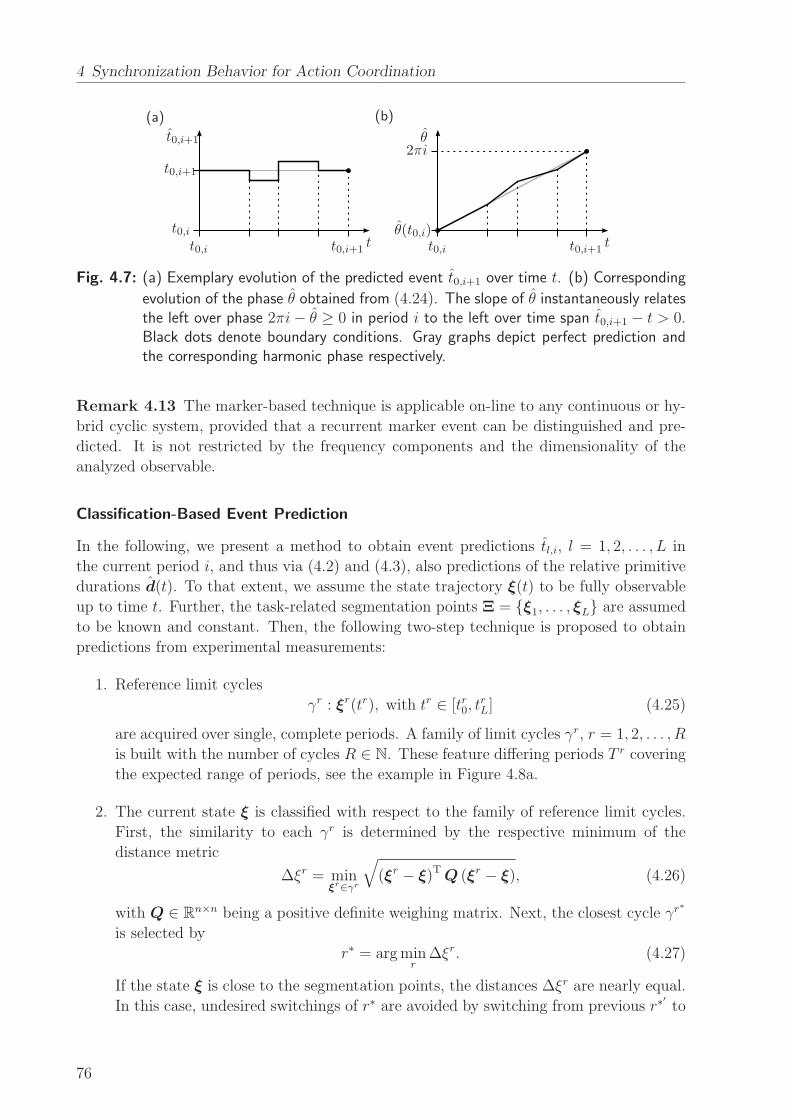
4 Synchronization Behavior for Action Coordination
(a) (b)
t tt0,i
t0,i t0,i
t0,i+1
t0,i+1 t0,i+1
2πi
θ(t0,i)
θt0,i+1
Fig. 4.7: (a) Exemplary evolution of the predicted event t0,i+1 over time t. (b) Corresponding
evolution of the phase θ obtained from (4.24). The slope of θ instantaneously relatesthe left over phase 2πi− θ ≥ 0 in period i to the left over time span t0,i+1 − t > 0.Black dots denote boundary conditions. Gray graphs depict perfect prediction andthe corresponding harmonic phase respectively.
Remark 4.13 The marker-based technique is applicable on-line to any continuous or hy-
brid cyclic system, provided that a recurrent marker event can be distinguished and pre-
dicted. It is not restricted by the frequency components and the dimensionality of the
analyzed observable.
Classification-Based Event Prediction
In the following, we present a method to obtain event predictions tl,i, l = 1, 2, . . . , L in
the current period i, and thus via (4.2) and (4.3), also predictions of the relative primitive
durations d(t). To that extent, we assume the state trajectory ξ(t) to be fully observable
up to time t. Further, the task-related segmentation points Ξ = {ξ1, . . . , ξL} are assumed
to be known and constant. Then, the following two-step technique is proposed to obtain
predictions from experimental measurements:
1. Reference limit cycles
γr : ξr(tr), with tr ∈ [tr0, trL] (4.25)
are acquired over single, complete periods. A family of limit cycles γr, r = 1, 2, . . . , R
is built with the number of cycles R ∈ N. These feature differing periods T r covering
the expected range of periods, see the example in Figure 4.8a.
2. The current state ξ is classified with respect to the family of reference limit cycles.
First, the similarity to each γr is determined by the respective minimum of the
distance metric
∆ξr = minξr∈γr
√
(ξr − ξ)T Q (ξr − ξ), (4.26)
with Q ∈ Rn×n being a positive definite weighing matrix. Next, the closest cycle γr
∗
is selected by
r∗ = argminr
∆ξr. (4.27)
If the state ξ is close to the segmentation points, the distances ∆ξr are nearly equal.
In this case, undesired switchings of r∗ are avoided by switching from previous r∗′
to
76
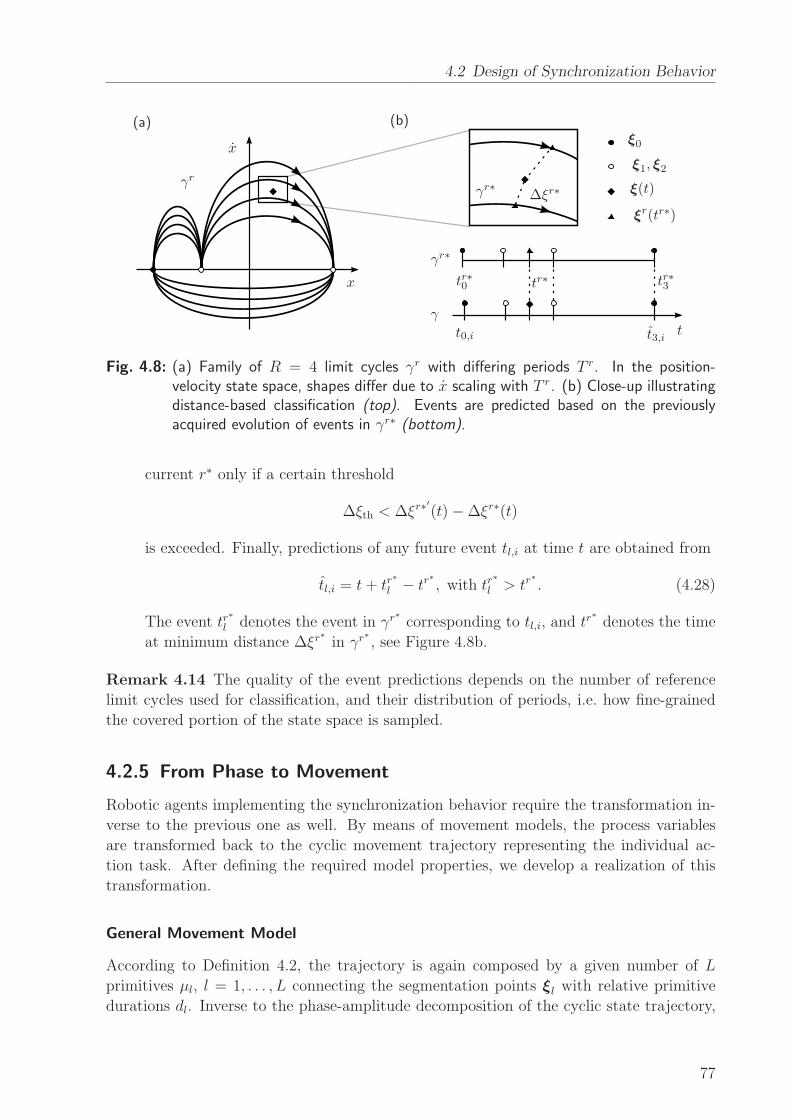
4.2 Design of Synchronization Behavior
(a) (b)
t
γr
γr∗
γr∗
γ
x
x
∆ξr∗
tr∗0 tr∗3tr∗
t0,i t3,i
ξ0
ξ1, ξ2
ξ(t)
ξr(tr∗)
Fig. 4.8: (a) Family of R = 4 limit cycles γr with differing periods T r. In the position-velocity state space, shapes differ due to x scaling with T r. (b) Close-up illustratingdistance-based classification (top). Events are predicted based on the previouslyacquired evolution of events in γr∗ (bottom).
current r∗ only if a certain threshold
∆ξth < ∆ξr∗′
(t)−∆ξr∗(t)
is exceeded. Finally, predictions of any future event tl,i at time t are obtained from
tl,i = t+ tr∗
l − tr∗
, with tr∗
l > tr∗
. (4.28)
The event tr∗
l denotes the event in γr∗
corresponding to tl,i, and tr∗ denotes the time
at minimum distance ∆ξr∗
in γr∗
, see Figure 4.8b.
Remark 4.14 The quality of the event predictions depends on the number of reference
limit cycles used for classification, and their distribution of periods, i.e. how fine-grained
the covered portion of the state space is sampled.
4.2.5 From Phase to Movement
Robotic agents implementing the synchronization behavior require the transformation in-
verse to the previous one as well. By means of movement models, the process variables
are transformed back to the cyclic movement trajectory representing the individual ac-
tion task. After defining the required model properties, we develop a realization of this
transformation.
General Movement Model
According to Definition 4.2, the trajectory is again composed by a given number of L
primitives µl, l = 1, . . . , L connecting the segmentation points ξl with relative primitive
durations dl. Inverse to the phase-amplitude decomposition of the cyclic state trajectory,
77
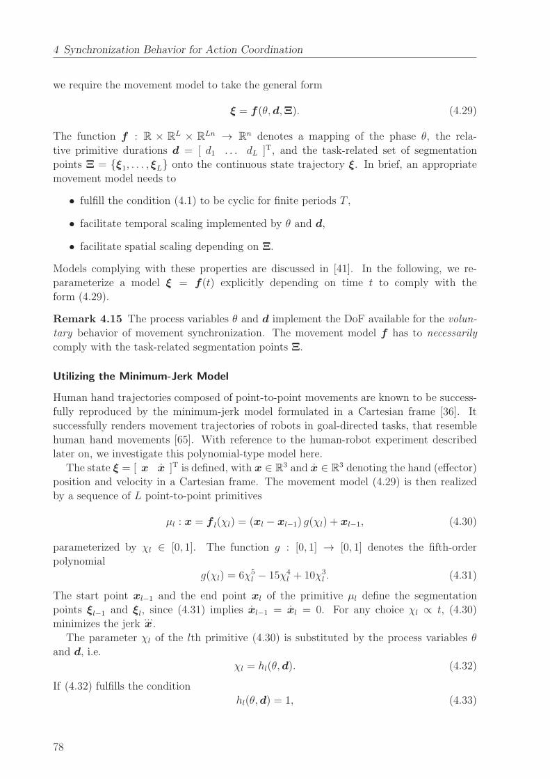
4 Synchronization Behavior for Action Coordination
we require the movement model to take the general form
ξ = f (θ,d,Ξ). (4.29)
The function f : R × RL × RLn → Rn denotes a mapping of the phase θ, the rela-
tive primitive durations d = [ d1 . . . dL ]T, and the task-related set of segmentation
points Ξ = {ξ1, . . . , ξL} onto the continuous state trajectory ξ. In brief, an appropriate
movement model needs to
• fulfill the condition (4.1) to be cyclic for finite periods T ,
• facilitate temporal scaling implemented by θ and d,
• facilitate spatial scaling depending on Ξ.
Models complying with these properties are discussed in [41]. In the following, we re-
parameterize a model ξ = f(t) explicitly depending on time t to comply with the
form (4.29).
Remark 4.15 The process variables θ and d implement the DoF available for the volun-
tary behavior of movement synchronization. The movement model f has to necessarily
comply with the task-related segmentation points Ξ.
Utilizing the Minimum-Jerk Model
Human hand trajectories composed of point-to-point movements are known to be success-
fully reproduced by the minimum-jerk model formulated in a Cartesian frame [36]. It
successfully renders movement trajectories of robots in goal-directed tasks, that resemble
human hand movements [65]. With reference to the human-robot experiment described
later on, we investigate this polynomial-type model here.
The state ξ = [ x x ]T is defined, with x ∈ R3 and x ∈ R
3 denoting the hand (effector)
position and velocity in a Cartesian frame. The movement model (4.29) is then realized
by a sequence of L point-to-point primitives
µl : x = f l(χl) = (xl − xl−1) g(χl) + xl−1, (4.30)
parameterized by χl ∈ [0, 1]. The function g : [0, 1] → [0, 1] denotes the fifth-order
polynomial
g(χl) = 6χ5l − 15χ4
l + 10χ3l . (4.31)
The start point xl−1 and the end point xl of the primitive µl define the segmentation
points ξl−1 and ξl, since (4.31) implies xl−1 = xl = 0. For any choice χl ∝ t, (4.30)
minimizes the jerk...x.
The parameter χl of the lth primitive (4.30) is substituted by the process variables θ
and d, i.e.
χl = hl(θ,d). (4.32)
If (4.32) fulfills the condition
hl(θ,d) = 1, (4.33)
78
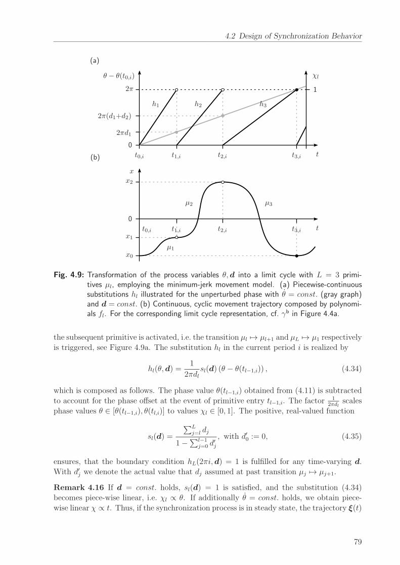
4.2 Design of Synchronization Behavior
(a)
(b)
t
t
x
2πd1
2π(d1+d2)
2π
θ − θ(t0,i) χl
0
0
1
t0,i
t0,i
t1,i
t1,i
t2,i
t2,i
t3,i
t3,i
x0
x1
x2
µ1
µ2 µ3
h1 h2 h3
Fig. 4.9: Transformation of the process variables θ,d into a limit cycle with L = 3 primi-tives µl, employing the minimum-jerk movement model. (a) Piecewise-continuoussubstitutions hl illustrated for the unperturbed phase with θ = const. (gray graph)and d = const. (b) Continuous, cyclic movement trajectory composed by polynomi-als fl. For the corresponding limit cycle representation, cf. γb in Figure 4.4a.
the subsequent primitive is activated, i.e. the transition µl 7→ µl+1 and µL 7→ µ1 respectively
is triggered, see Figure 4.9a. The substitution hl in the current period i is realized by
hl(θ,d) =1
2πdlsl(d) (θ − θ(tl−1,i)) , (4.34)
which is composed as follows. The phase value θ(tl−1,i) obtained from (4.11) is subtracted
to account for the phase offset at the event of primitive entry tl−1,i. The factor 12πdl
scales
phase values θ ∈ [θ(tl−1,i), θ(tl,i)] to values χl ∈ [0, 1]. The positive, real-valued function
sl(d) =
∑Lj=l dj
1−∑l−1
j=0 d′j
, with d′0 := 0, (4.35)
ensures, that the boundary condition hL(2πi,d) = 1 is fulfilled for any time-varying d.
With d′j we denote the actual value that dj assumed at past transition µj 7→ µj+1.
Remark 4.16 If d = const. holds, sl(d) = 1 is satisfied, and the substitution (4.34)
becomes piece-wise linear, i.e. χl ∝ θ. If additionally θ = const. holds, we obtain piece-
wise linear χ ∝ t. Thus, if the synchronization process is in steady state, the trajectory ξ(t)
79
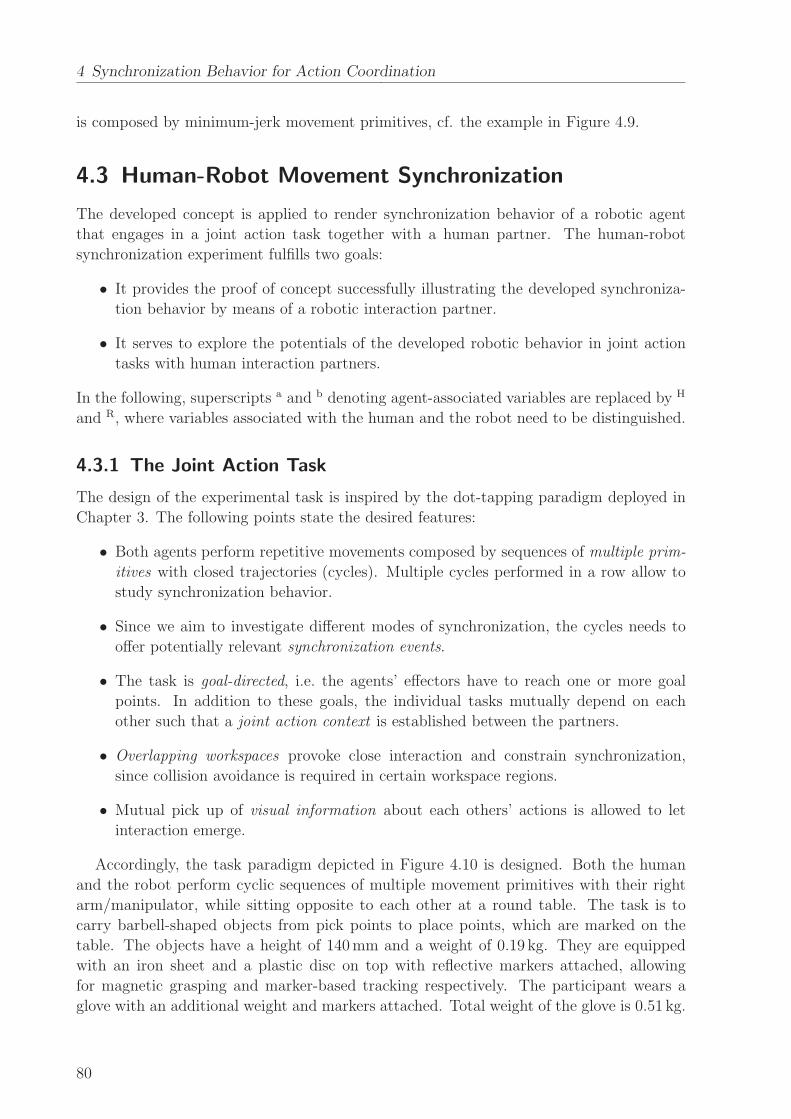
4 Synchronization Behavior for Action Coordination
is composed by minimum-jerk movement primitives, cf. the example in Figure 4.9.
4.3 Human-Robot Movement Synchronization
The developed concept is applied to render synchronization behavior of a robotic agent
that engages in a joint action task together with a human partner. The human-robot
synchronization experiment fulfills two goals:
• It provides the proof of concept successfully illustrating the developed synchroniza-
tion behavior by means of a robotic interaction partner.
• It serves to explore the potentials of the developed robotic behavior in joint action
tasks with human interaction partners.
In the following, superscripts a and b denoting agent-associated variables are replaced by H
and R, where variables associated with the human and the robot need to be distinguished.
4.3.1 The Joint Action Task
The design of the experimental task is inspired by the dot-tapping paradigm deployed in
Chapter 3. The following points state the desired features:
• Both agents perform repetitive movements composed by sequences of multiple prim-
itives with closed trajectories (cycles). Multiple cycles performed in a row allow to
study synchronization behavior.
• Since we aim to investigate different modes of synchronization, the cycles needs to
offer potentially relevant synchronization events.
• The task is goal-directed, i.e. the agents’ effectors have to reach one or more goal
points. In addition to these goals, the individual tasks mutually depend on each
other such that a joint action context is established between the partners.
• Overlapping workspaces provoke close interaction and constrain synchronization,
since collision avoidance is required in certain workspace regions.
• Mutual pick up of visual information about each others’ actions is allowed to let
interaction emerge.
Accordingly, the task paradigm depicted in Figure 4.10 is designed. Both the human
and the robot perform cyclic sequences of multiple movement primitives with their right
arm/manipulator, while sitting opposite to each other at a round table. The task is to
carry barbell-shaped objects from pick points to place points, which are marked on the
table. The objects have a height of 140mm and a weight of 0.19 kg. They are equipped
with an iron sheet and a plastic disc on top with reflective markers attached, allowing
for magnetic grasping and marker-based tracking respectively. The participant wears a
glove with an additional weight and markers attached. Total weight of the glove is 0.51 kg.
80
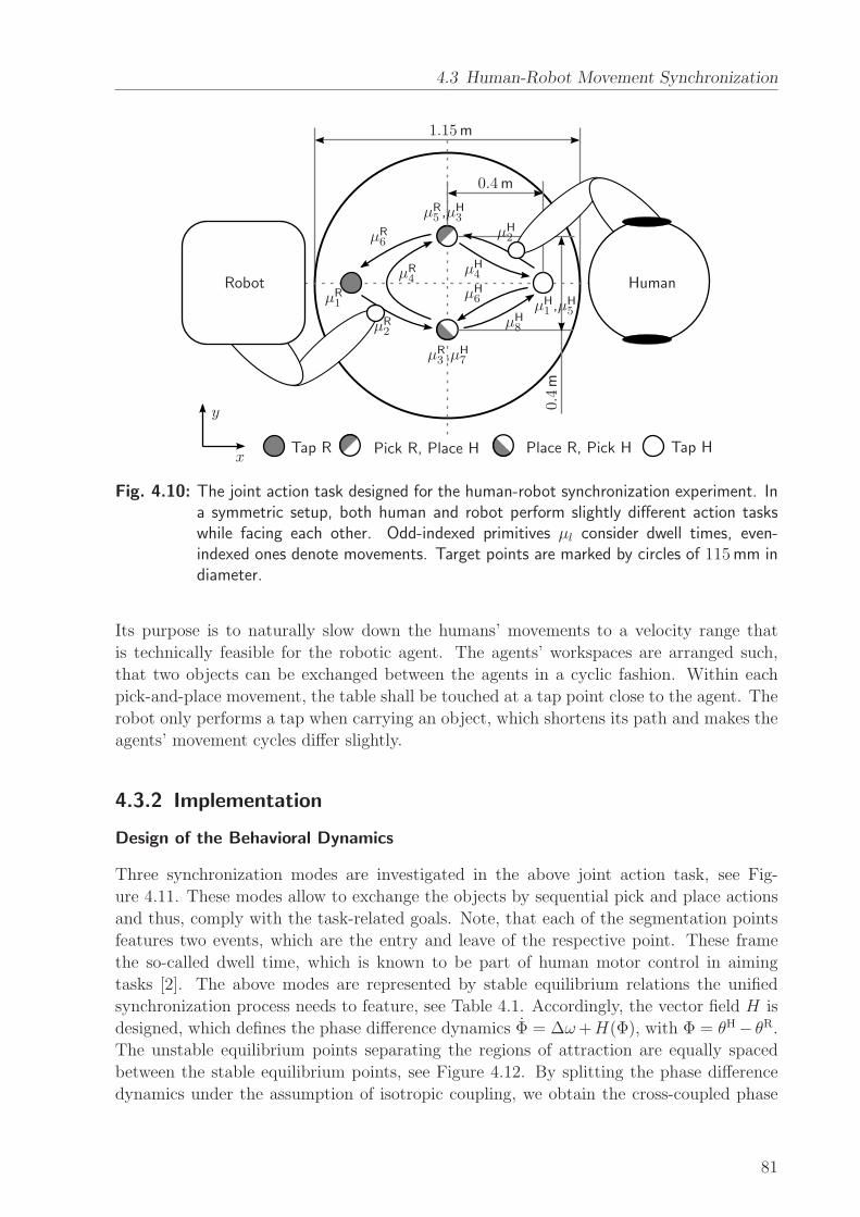
4.3 Human-Robot Movement Synchronization
HumanRobot
x
y
µR1
µR2
µR3 ,µ
H7
µR4
µR5 ,µ
H3
µR6
µH1 ,µ
H5
µH2
µH4
µH6
µH8
1.15m
0.4m
0.4m
Tap R Pick R, Place H Tap HPlace R, Pick H
Fig. 4.10: The joint action task designed for the human-robot synchronization experiment. Ina symmetric setup, both human and robot perform slightly different action taskswhile facing each other. Odd-indexed primitives µl consider dwell times, even-indexed ones denote movements. Target points are marked by circles of 115mm indiameter.
Its purpose is to naturally slow down the humans’ movements to a velocity range that
is technically feasible for the robotic agent. The agents’ workspaces are arranged such,
that two objects can be exchanged between the agents in a cyclic fashion. Within each
pick-and-place movement, the table shall be touched at a tap point close to the agent. The
robot only performs a tap when carrying an object, which shortens its path and makes the
agents’ movement cycles differ slightly.
4.3.2 Implementation
Design of the Behavioral Dynamics
Three synchronization modes are investigated in the above joint action task, see Fig-
ure 4.11. These modes allow to exchange the objects by sequential pick and place actions
and thus, comply with the task-related goals. Note, that each of the segmentation points
features two events, which are the entry and leave of the respective point. These frame
the so-called dwell time, which is known to be part of human motor control in aiming
tasks [2]. The above modes are represented by stable equilibrium relations the unified
synchronization process needs to feature, see Table 4.1. Accordingly, the vector field H is
designed, which defines the phase difference dynamics Φ = ∆ω+H(Φ), with Φ = θH− θR.
The unstable equilibrium points separating the regions of attraction are equally spaced
between the stable equilibrium points, see Figure 4.12. By splitting the phase difference
dynamics under the assumption of isotropic coupling, we obtain the cross-coupled phase
81

4 Synchronization Behavior for Action Coordination
(a)
(b)
t
t
t
tdH1 dH2 dH3 dH4 dH5 dH6 dH7 dH8
dR1
dR1
dR1
dR2
dR2
dR2
dR3
dR3
dR3
dR4
dR4
dR4
dR5
dR5
dR5
dR6
dR6
dR6
γH
γR
γR
γR
Tap
Tap
Tap
TapTap Pick
Pick
Pick
Pick
Place
Place
Place
Place
Mode1
Mode2
Mode3
Fig. 4.11: (a) The evolution of events for the experimental task, with the relative durations dlcorresponding to the primitives µl in Figure 4.10. Again, odd-indexed durationsare due to expected dwell times in the segmentation points. (b) The cycle γR
synchronized to γH in three different modes, denoted mode 1-3. Vertical dashedlines indicate synchronized events. Intuitively speaking, the human precedes therobot in mode 2 and vice versa in mode 3.
entrainment process
θH = ωH +H(θH − θR)
2(4.36)
θR = ωR − H(θH − θR)
2. (4.37)
The processing delay ∆tp of the robot is compensated by adding the constant phase
shift ∆θH = ωR∆tp to the human phase estimate θH.
The entrainment process of the relative primitive durations is realized according to the
Tab. 4.1: Stable equilibrium relations of the implemented synchronization process.
Mode Phase difference Φr,e,m Relative primitive durations dH/R
m = 1 Φr,e,1 = 0 dH1 = dR1 , dH2 = dR2 , dH3 = dR3 ,dH7 = dR5 , dH8 = dR6
m = 2 Φr,e,2 = 2π∑6
j=5 dRj dH1 = dR5 , dH2 = dR6 , dH3 = dR1 ,
dH4 = dR2 , dH5 = dR3
m = 3 Φr,e,3 = 2π∑6
j=3 dRj dH1 = dR3 , dH5 = dR5 , dH6 = dR6 ,
dH7 = dR1 , dH8 = dR2
82
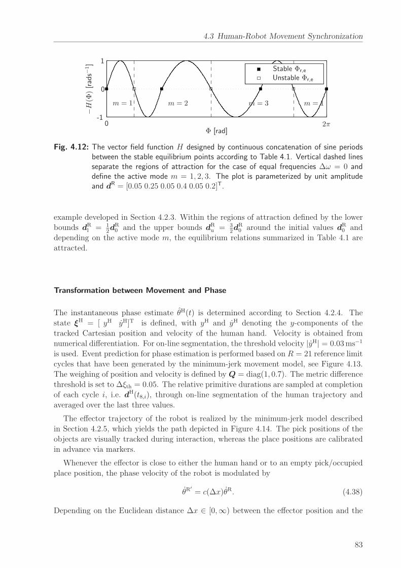
4.3 Human-Robot Movement Synchronization
Φ [rad]
−H(Φ
)[rads−
1]
0
0 2π-1
1Stable Φr,e
Unstable Φr,e
m = 1m = 1 m = 2 m = 3
Fig. 4.12: The vector field function H designed by continuous concatenation of sine periodsbetween the stable equilibrium points according to Table 4.1. Vertical dashed linesseparate the regions of attraction for the case of equal frequencies ∆ω = 0 anddefine the active mode m = 1, 2, 3. The plot is parameterized by unit amplitudeand dR = [0.05 0.25 0.05 0.4 0.05 0.2]T.
example developed in Section 4.2.3. Within the regions of attraction defined by the lower
bounds dRl = 1
2dR0 and the upper bounds dR
u = 32dR0 around the initial values dR
0 and
depending on the active mode m, the equilibrium relations summarized in Table 4.1 are
attracted.
Transformation between Movement and Phase
The instantaneous phase estimate θH(t) is determined according to Section 4.2.4. The
state ξH = [ yH yH]T is defined, with yH and yH denoting the y-components of the
tracked Cartesian position and velocity of the human hand. Velocity is obtained from
numerical differentiation. For on-line segmentation, the threshold velocity |yH| = 0.03ms−1
is used. Event prediction for phase estimation is performed based on R = 21 reference limit
cycles that have been generated by the minimum-jerk movement model, see Figure 4.13.
The weighing of position and velocity is defined by Q = diag(1, 0.7). The metric difference
threshold is set to ∆ξth = 0.05. The relative primitive durations are sampled at completion
of each cycle i, i.e. dH(t8,i), through on-line segmentation of the human trajectory and
averaged over the last three values.
The effector trajectory of the robot is realized by the minimum-jerk model described
in Section 4.2.5, which yields the path depicted in Figure 4.14. The pick positions of the
objects are visually tracked during interaction, whereas the place positions are calibrated
in advance via markers.
Whenever the effector is close to either the human hand or to an empty pick/occupied
place position, the phase velocity of the robot is modulated by
θR′
= c(∆x)θR. (4.38)
Depending on the Euclidean distance ∆x ∈ [0,∞) between the effector position and the
83
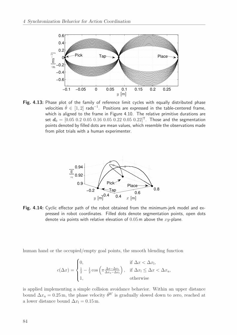
4 Synchronization Behavior for Action Coordination
−0.1 −0.05 0 0.05 0.1 0.15 0.2 0.25
−0.6
−0.4
−0.2
0
0.2
0.4
0.6
Pick PlaceTap
y [m]
y[m
s−1]
Fig. 4.13: Phase plot of the family of reference limit cycles with equally distributed phasevelocities θ ∈ [1, 2] rads−1. Positions are expressed in the table-centered frame,which is aligned to the frame in Figure 4.10. The relative primitive durations areset d0 = [0.05 0.2 0.05 0.16 0.05 0.22 0.05 0.22]T. Those and the segmentationpoints denoted by filled dots are mean values, which resemble the observations madefrom pilot trials with a human experimenter.
0.40.6
0.8
−0.4−0.2
0.9
0.92
0.94
Pick
TapPlace
x [m]y [m]
z[m
]
Fig. 4.14: Cyclic effector path of the robot obtained from the minimum-jerk model and ex-pressed in robot coordinates. Filled dots denote segmentation points, open dotsdenote via points with relative elevation of 0.05m above the xy-plane.
human hand or the occupied/empty goal points, the smooth blending function
c(∆x) =
0, if ∆x < ∆xl,12− 1
2cos
(
π ∆x−∆xl
∆xu−∆xl
)
, if ∆xl ≤ ∆x < ∆xu,
1, otherwise
is applied implementing a simple collision avoidance behavior. Within an upper distance
bound ∆xu = 0.25m, the phase velocity θR′
is gradually slowed down to zero, reached at
a lower distance bound ∆xl = 0.15m.
84
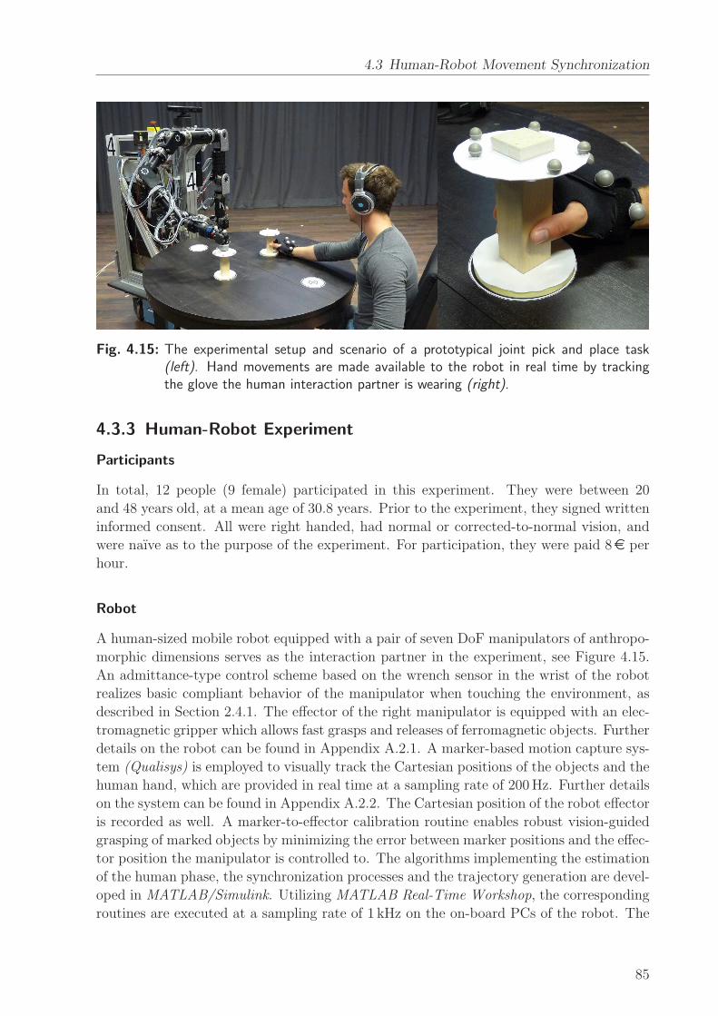
4.3 Human-Robot Movement Synchronization
Fig. 4.15: The experimental setup and scenario of a prototypical joint pick and place task(left). Hand movements are made available to the robot in real time by trackingthe glove the human interaction partner is wearing (right).
4.3.3 Human-Robot Experiment
Participants
In total, 12 people (9 female) participated in this experiment. They were between 20
and 48 years old, at a mean age of 30.8 years. Prior to the experiment, they signed written
informed consent. All were right handed, had normal or corrected-to-normal vision, and
were naıve as to the purpose of the experiment. For participation, they were paid 8e per
hour.
Robot
A human-sized mobile robot equipped with a pair of seven DoF manipulators of anthropo-
morphic dimensions serves as the interaction partner in the experiment, see Figure 4.15.
An admittance-type control scheme based on the wrench sensor in the wrist of the robot
realizes basic compliant behavior of the manipulator when touching the environment, as
described in Section 2.4.1. The effector of the right manipulator is equipped with an elec-
tromagnetic gripper which allows fast grasps and releases of ferromagnetic objects. Further
details on the robot can be found in Appendix A.2.1. A marker-based motion capture sys-
tem (Qualisys) is employed to visually track the Cartesian positions of the objects and the
human hand, which are provided in real time at a sampling rate of 200Hz. Further details
on the system can be found in Appendix A.2.2. The Cartesian position of the robot effector
is recorded as well. A marker-to-effector calibration routine enables robust vision-guided
grasping of marked objects by minimizing the error between marker positions and the effec-
tor position the manipulator is controlled to. The algorithms implementing the estimation
of the human phase, the synchronization processes and the trajectory generation are devel-
oped in MATLAB/Simulink. Utilizing MATLAB Real-Time Workshop, the corresponding
routines are executed at a sampling rate of 1 kHz on the on-board PCs of the robot. The
85
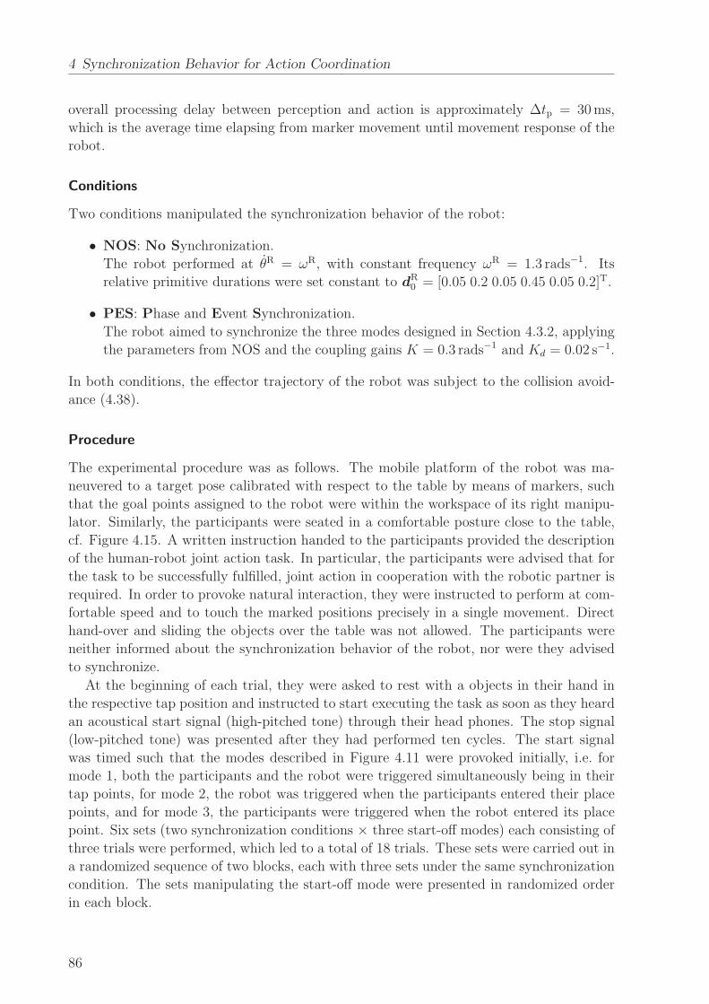
4 Synchronization Behavior for Action Coordination
overall processing delay between perception and action is approximately ∆tp = 30ms,
which is the average time elapsing from marker movement until movement response of the
robot.
Conditions
Two conditions manipulated the synchronization behavior of the robot:
• NOS: No Synchronization.
The robot performed at θR = ωR, with constant frequency ωR = 1.3 rads−1. Its
relative primitive durations were set constant to dR0 = [0.05 0.2 0.05 0.45 0.05 0.2]T.
• PES: Phase and Event Synchronization.
The robot aimed to synchronize the three modes designed in Section 4.3.2, applying
the parameters from NOS and the coupling gains K = 0.3 rads−1 and Kd = 0.02 s−1.
In both conditions, the effector trajectory of the robot was subject to the collision avoid-
ance (4.38).
Procedure
The experimental procedure was as follows. The mobile platform of the robot was ma-
neuvered to a target pose calibrated with respect to the table by means of markers, such
that the goal points assigned to the robot were within the workspace of its right manipu-
lator. Similarly, the participants were seated in a comfortable posture close to the table,
cf. Figure 4.15. A written instruction handed to the participants provided the description
of the human-robot joint action task. In particular, the participants were advised that for
the task to be successfully fulfilled, joint action in cooperation with the robotic partner is
required. In order to provoke natural interaction, they were instructed to perform at com-
fortable speed and to touch the marked positions precisely in a single movement. Direct
hand-over and sliding the objects over the table was not allowed. The participants were
neither informed about the synchronization behavior of the robot, nor were they advised
to synchronize.
At the beginning of each trial, they were asked to rest with a objects in their hand in
the respective tap position and instructed to start executing the task as soon as they heard
an acoustical start signal (high-pitched tone) through their head phones. The stop signal
(low-pitched tone) was presented after they had performed ten cycles. The start signal
was timed such that the modes described in Figure 4.11 were provoked initially, i.e. for
mode 1, both the participants and the robot were triggered simultaneously being in their
tap points, for mode 2, the robot was triggered when the participants entered their place
points, and for mode 3, the participants were triggered when the robot entered its place
point. Six sets (two synchronization conditions × three start-off modes) each consisting of
three trials were performed, which led to a total of 18 trials. These sets were carried out in
a randomized sequence of two blocks, each with three sets under the same synchronization
condition. The sets manipulating the start-off mode were presented in randomized order
in each block.
86
4.3 Human-Robot Movement Synchronization
4.3.4 Evaluation Criteria
The following measures are deployed to assess the synchronization behavior observed in
the experiment.
Event Synchronization
The synchronization of events targeted by the behavioral dynamics of the robot is assessed
based on the measured Cartesian position trajectories of the human hand xH(t) and the
robot effector xR(t). Those are recorded simultaneously by the motion capture system, thus
differing processing delays are eliminated. Trajectory segmentation and event extraction
is performed identically to the implementation described in Section 4.3.2. According to
Definition 4.6, we calculate for each synchronization mode m the temporal lags within
all event pairs (tHlH, tRlR), where the indexes lH/R are chosen corresponding to the events
synchronized in mode m. For each mode m, the lag magnitudes are averaged per period iH,
i.e. over event pairs with tHl,iH ∈ [tH0,iH , tH8,iH). Those averages provide continuous measures
of asynchrony, which we denote ASYNm,iH . In each period iH, the best fitting one out of
the three modes is detected by selecting the smallest asynchrony. The per-trial average of
the latter over all periods IH reads
MASYN =1
IH
IH∑
iH=1
minm
ASYNm,iH , (4.39)
which we call the mode-related asynchrony.
Remark 4.17 The mode-related asynchrony quantifies the mean time lag between mul-
tiple event pairs, measured in seconds. Only complete sets of event pairs corresponding to
the defined modes are probed.
Mode Distribution and Mode Switches
At any time, one of three synchronization modes is considered to be active, and pursued
by the robot in condition PES. According to the vector field design cf. Figure 4.12 and
Table 4.1, we determine the active mode
m =
1, if Φr <Φr,e,1+Φr,e,2
2∨ Φr >
Φr,e,3+2π
2,
2, if Φr ≥ Φr,e,1+Φr,e,2
2∧ Φr ≤ Φr,e,2+Φr,e,3
2,
3, otherwise.
(4.40)
Given the evolution of the active mode m(t), we analyze the relative distribution of
modes Nm
Nas an indicator of the within-dyad preferred synchronization modes, where Nm is
the number of samples in active mode m and N the total number of samples per trial. Fur-
thermore, the temporal persistence of modes is measured by the number of mode switches,
i.e. the number of samples {j | m(tj) 6= m(tj+1)} per trial.
87
4 Synchronization Behavior for Action Coordination
Synchronization Index
Phase synchronization is again quantified by means of the synchronization index SI given
by (3.5). However, the synchronization concept in this chapter introduces multiple modes,
represented by differing equilibrium phase differences. Trials with one or more mode
switches would heavily degrade the SI. Hence, we propose to calculate the synchroniza-
tion index separately for epochs of the same active mode. The active mode is determined
by (4.40). The resulting indexes SIm are then combined per trial into the mode-related
synchronization index
MSI =1
N
3∑
m=1
NmSIm, (4.41)
weighted by the respective number of samples Nm in mode m.
Remark 4.18 The MSI lies in the interval [0, 1]. Given a perfectly uniform distribution
of Φ(t), it would equal zero. It equals one only if the synchronization process is persistently
in steady-state, which means that all samples of Φ(t) point to the same direction.
Entrainment Error of the Relative Primitive Durations
As shown in our synchronization concept, the entrainment across the relative primitive
durations dH/R is essential to the synchronization of multiple event pairs. It is assessed by
the root-mean-square error defined as the residual
RMSE(dHlH = dRlR) =
√
√
√
√
1
N
N∑
j=1
(
dHlH(tj)− dR
lR(tj)
)2, (4.42)
with the primitive indexes lH/R chosen corresponding to the equilibrium relations summa-
rized in Table 4.1. For each relation and epoch of the same active mode m given by (4.40),
the entrainment errors are obtained from (4.42) and averaged over the five mode-dependent
equilibrium relations afterwards, yielding the errors RMSEd,m. Analogously to the above
definition of the mode-related synchronization index (4.41), those are then combined by
the weighted average
RMSEd =1
N
3∑
m=1
NmRMSEd,m, (4.43)
which assesses the overall entrainment error of dH/R.
4.4 Experimental Results
The synchronization behavior is assessed through measures relying on internal variables
of the robot. The observable degree of event synchronization between the movements is
evaluated as external measure. Feedback gathered from a short questionnaire is reported
as well. Note, that the results presented in the following are based on a group of nine
participants unless stated otherwise. The remaining group of three participants performed
88
4.4 Experimental Results
at movement speeds either far below or above the speed range the robot is capable of
moving at, thus impeding movement synchronization in the experiment. Possible reasons
are discussed in Section 4.5.
4.4.1 External Assessment of Synchronization
The following results allow to explain, how far the overall goal of our synchronization con-
cept is reached objectively, i.e. if it fosters the entrainment of movements by synchronizing
multiple event pairs. In addition, subjective feedback from the participants gives rise to
discuss some perceived effects.
Subjective Reasoning
After having completed the experiment, participants were asked whether or not they had
the feeling that the robot reacted to them. In case of a positive answer, they were asked
to state if they found that perceived reactiveness pleasant (yes/no) and to give reasons
for this answer. Eleven out of twelve participants recognized reactiveness of the robot in
response to their movements during parts of the experiment. Ten out of eleven participants
who answered positively stated that they liked the perceived reactiveness, giving reasons
such as:
• It makes the robot appear lively.
• Having the control over task speed is pleasant.
• Adjustment towards similar speed is pleasant.
• It fosters smoother interaction.
• Negotiation among partners is beneficial.
• It is a nice feeling, but a bit uncanny as well.
The participant who disliked the reactive behavior of the robot described the interaction
as flurry and unsteady.
Event Synchronization
The evaluation of the objective measure of event synchronization introduced in Sec-
tion 4.3.4, the mode-related asynchrony MASYN, is depicted in Figure 4.16. A 2 × 3
repeated measures ANOVA with the within subject factors condition (NOS, PES) and
start-off mode (1-3) reveals a clear decrease of asynchrony in each of the start-off
modes, F (1, 8) = 18.06, p = .003, if the robot applies synchronization behavior, i.e. the
condition PES. Irrespective of the synchronization condition, start-off mode 1 numerically
results in lowest asynchrony values, whereas a slight trend towards an increased asyn-
chrony is visible for mode 2 and 3. However, differences between start-off modes were not
significant and no significant interaction effect was observed, both p > .4.
89
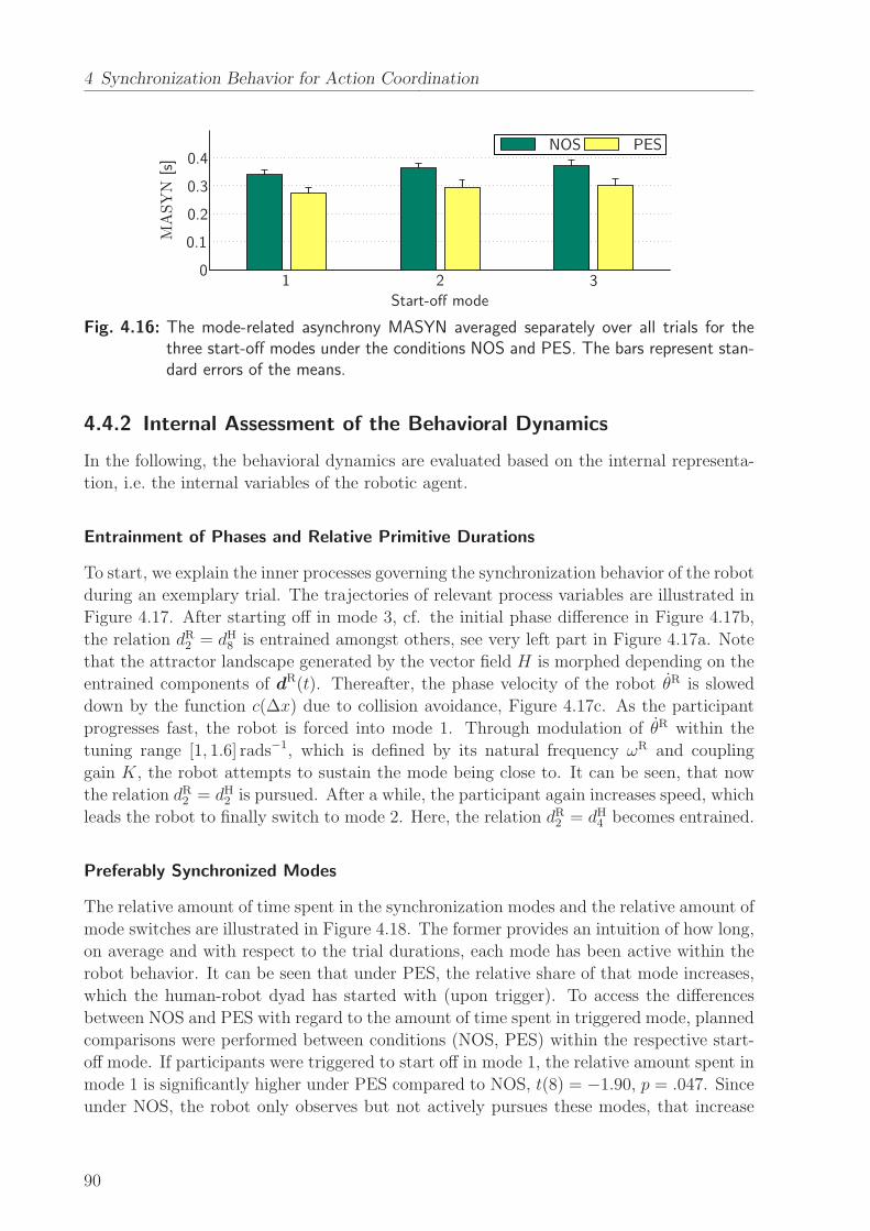
4 Synchronization Behavior for Action Coordination
Start-off mode
MASYN
[s]
NOS PES
0.1
0.2
0.3
0.4
01 2 3
Fig. 4.16: The mode-related asynchrony MASYN averaged separately over all trials for thethree start-off modes under the conditions NOS and PES. The bars represent stan-dard errors of the means.
4.4.2 Internal Assessment of the Behavioral Dynamics
In the following, the behavioral dynamics are evaluated based on the internal representa-
tion, i.e. the internal variables of the robotic agent.
Entrainment of Phases and Relative Primitive Durations
To start, we explain the inner processes governing the synchronization behavior of the robot
during an exemplary trial. The trajectories of relevant process variables are illustrated in
Figure 4.17. After starting off in mode 3, cf. the initial phase difference in Figure 4.17b,
the relation dR2 = dH8 is entrained amongst others, see very left part in Figure 4.17a. Note
that the attractor landscape generated by the vector field H is morphed depending on the
entrained components of dR(t). Thereafter, the phase velocity of the robot θR is slowed
down by the function c(∆x) due to collision avoidance, Figure 4.17c. As the participant
progresses fast, the robot is forced into mode 1. Through modulation of θR within the
tuning range [1, 1.6] rads−1, which is defined by its natural frequency ωR and coupling
gain K, the robot attempts to sustain the mode being close to. It can be seen, that now
the relation dR2 = dH2 is pursued. After a while, the participant again increases speed, which
leads the robot to finally switch to mode 2. Here, the relation dR2 = dH4 becomes entrained.
Preferably Synchronized Modes
The relative amount of time spent in the synchronization modes and the relative amount of
mode switches are illustrated in Figure 4.18. The former provides an intuition of how long,
on average and with respect to the trial durations, each mode has been active within the
robot behavior. It can be seen that under PES, the relative share of that mode increases,
which the human-robot dyad has started with (upon trigger). To access the differences
between NOS and PES with regard to the amount of time spent in triggered mode, planned
comparisons were performed between conditions (NOS, PES) within the respective start-
off mode. If participants were triggered to start off in mode 1, the relative amount spent in
mode 1 is significantly higher under PES compared to NOS, t(8) = −1.90, p = .047. Since
under NOS, the robot only observes but not actively pursues these modes, that increase
90
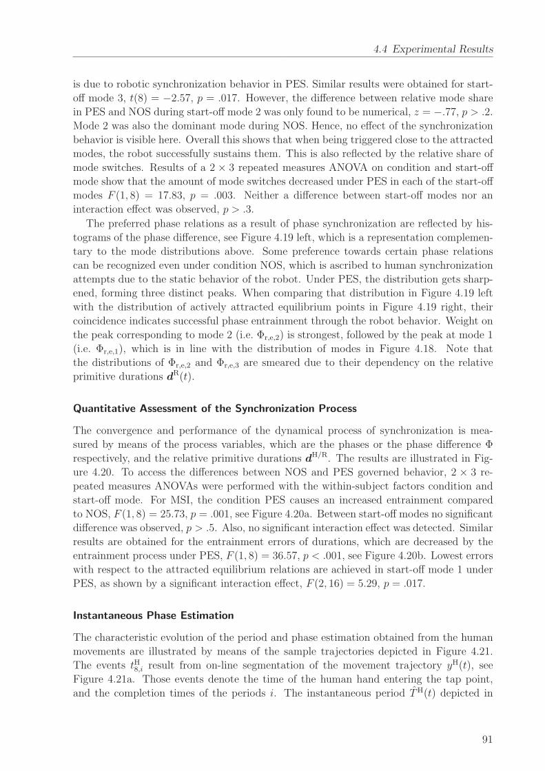
4.4 Experimental Results
is due to robotic synchronization behavior in PES. Similar results were obtained for start-
off mode 3, t(8) = −2.57, p = .017. However, the difference between relative mode share
in PES and NOS during start-off mode 2 was only found to be numerical, z = −.77, p > .2.
Mode 2 was also the dominant mode during NOS. Hence, no effect of the synchronization
behavior is visible here. Overall this shows that when being triggered close to the attracted
modes, the robot successfully sustains them. This is also reflected by the relative share of
mode switches. Results of a 2 × 3 repeated measures ANOVA on condition and start-off
mode show that the amount of mode switches decreased under PES in each of the start-off
modes F (1, 8) = 17.83, p = .003. Neither a difference between start-off modes nor an
interaction effect was observed, p > .3.
The preferred phase relations as a result of phase synchronization are reflected by his-
tograms of the phase difference, see Figure 4.19 left, which is a representation complemen-
tary to the mode distributions above. Some preference towards certain phase relations
can be recognized even under condition NOS, which is ascribed to human synchronization
attempts due to the static behavior of the robot. Under PES, the distribution gets sharp-
ened, forming three distinct peaks. When comparing that distribution in Figure 4.19 left
with the distribution of actively attracted equilibrium points in Figure 4.19 right, their
coincidence indicates successful phase entrainment through the robot behavior. Weight on
the peak corresponding to mode 2 (i.e. Φr,e,2) is strongest, followed by the peak at mode 1
(i.e. Φr,e,1), which is in line with the distribution of modes in Figure 4.18. Note that
the distributions of Φr,e,2 and Φr,e,3 are smeared due to their dependency on the relative
primitive durations dR(t).
Quantitative Assessment of the Synchronization Process
The convergence and performance of the dynamical process of synchronization is mea-
sured by means of the process variables, which are the phases or the phase difference Φ
respectively, and the relative primitive durations dH/R. The results are illustrated in Fig-
ure 4.20. To access the differences between NOS and PES governed behavior, 2 × 3 re-
peated measures ANOVAs were performed with the within-subject factors condition and
start-off mode. For MSI, the condition PES causes an increased entrainment compared
to NOS, F (1, 8) = 25.73, p = .001, see Figure 4.20a. Between start-off modes no significant
difference was observed, p > .5. Also, no significant interaction effect was detected. Similar
results are obtained for the entrainment errors of durations, which are decreased by the
entrainment process under PES, F (1, 8) = 36.57, p < .001, see Figure 4.20b. Lowest errors
with respect to the attracted equilibrium relations are achieved in start-off mode 1 under
PES, as shown by a significant interaction effect, F (2, 16) = 5.29, p = .017.
Instantaneous Phase Estimation
The characteristic evolution of the period and phase estimation obtained from the human
movements are illustrated by means of the sample trajectories depicted in Figure 4.21.
The events tH8,i result from on-line segmentation of the movement trajectory yH(t), see
Figure 4.21a. Those events denote the time of the human hand entering the tap point,
and the completion times of the periods i. The instantaneous period TH(t) depicted in
91
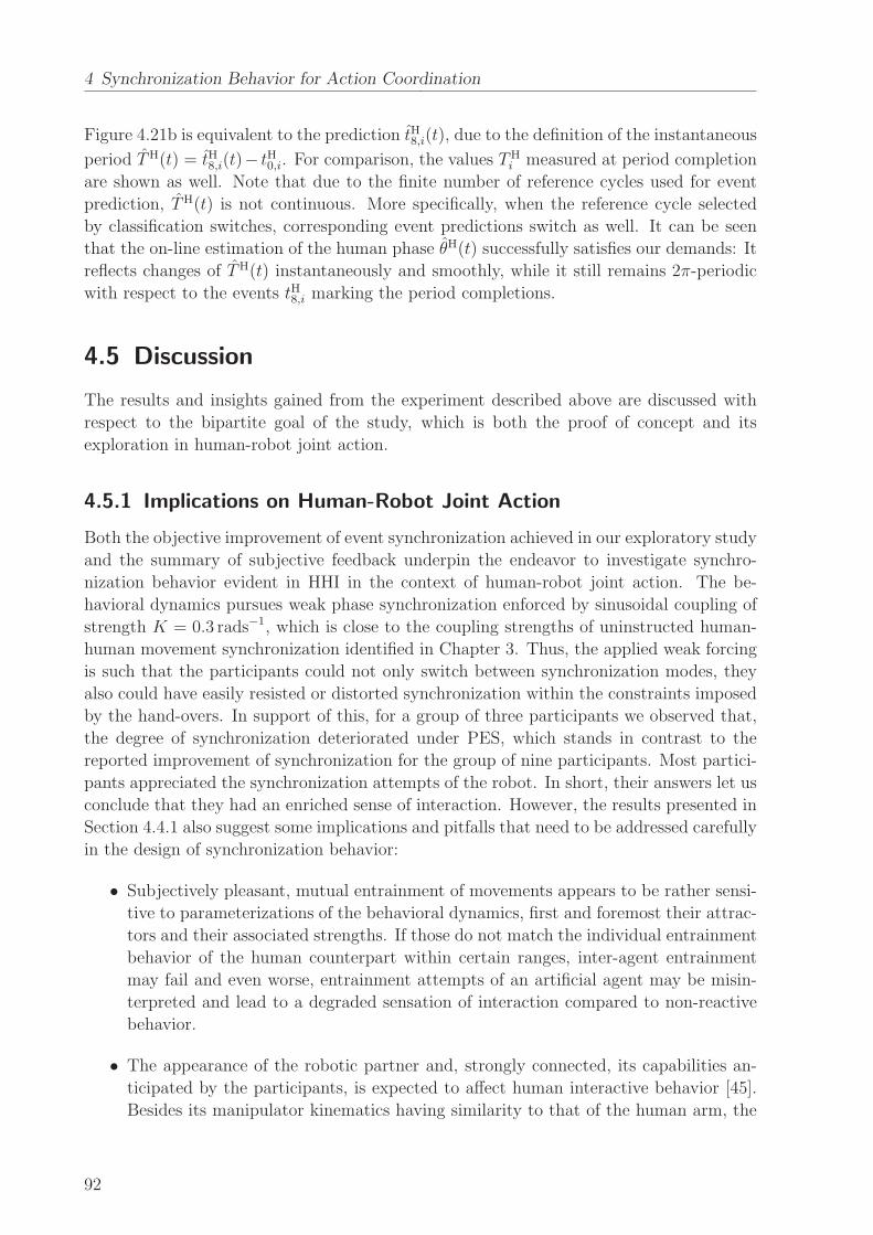
4 Synchronization Behavior for Action Coordination
Figure 4.21b is equivalent to the prediction tH8,i(t), due to the definition of the instantaneous
period TH(t) = tH8,i(t)− tH0,i. For comparison, the values THi measured at period completion
are shown as well. Note that due to the finite number of reference cycles used for event
prediction, TH(t) is not continuous. More specifically, when the reference cycle selected
by classification switches, corresponding event predictions switch as well. It can be seen
that the on-line estimation of the human phase θH(t) successfully satisfies our demands: It
reflects changes of TH(t) instantaneously and smoothly, while it still remains 2π-periodic
with respect to the events tH8,i marking the period completions.
4.5 Discussion
The results and insights gained from the experiment described above are discussed with
respect to the bipartite goal of the study, which is both the proof of concept and its
exploration in human-robot joint action.
4.5.1 Implications on Human-Robot Joint Action
Both the objective improvement of event synchronization achieved in our exploratory study
and the summary of subjective feedback underpin the endeavor to investigate synchro-
nization behavior evident in HHI in the context of human-robot joint action. The be-
havioral dynamics pursues weak phase synchronization enforced by sinusoidal coupling of
strength K = 0.3 rads−1, which is close to the coupling strengths of uninstructed human-
human movement synchronization identified in Chapter 3. Thus, the applied weak forcing
is such that the participants could not only switch between synchronization modes, they
also could have easily resisted or distorted synchronization within the constraints imposed
by the hand-overs. In support of this, for a group of three participants we observed that,
the degree of synchronization deteriorated under PES, which stands in contrast to the
reported improvement of synchronization for the group of nine participants. Most partici-
pants appreciated the synchronization attempts of the robot. In short, their answers let us
conclude that they had an enriched sense of interaction. However, the results presented in
Section 4.4.1 also suggest some implications and pitfalls that need to be addressed carefully
in the design of synchronization behavior:
• Subjectively pleasant, mutual entrainment of movements appears to be rather sensi-
tive to parameterizations of the behavioral dynamics, first and foremost their attrac-
tors and their associated strengths. If those do not match the individual entrainment
behavior of the human counterpart within certain ranges, inter-agent entrainment
may fail and even worse, entrainment attempts of an artificial agent may be misin-
terpreted and lead to a degraded sensation of interaction compared to non-reactive
behavior.
• The appearance of the robotic partner and, strongly connected, its capabilities an-
ticipated by the participants, is expected to affect human interactive behavior [45].
Besides its manipulator kinematics having similarity to that of the human arm, the
92
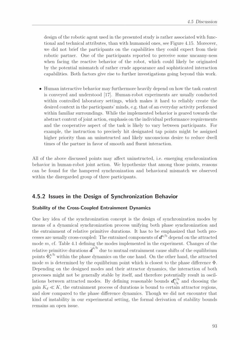
4.5 Discussion
design of the robotic agent used in the presented study is rather associated with func-
tional and technical attributes, than with humanoid ones, see Figure 4.15. Moreover,
we did not brief the participants on the capabilities they could expect from their
robotic partner. One of the participants reported to perceive some uncanny-ness
when facing the reactive behavior of the robot, which could likely be originated
by the potential mismatch of rather crude appearance and sophisticated interaction
capabilities. Both factors give rise to further investigations going beyond this work.
• Human interactive behavior may furthermore heavily depend on how the task context
is conveyed and understood [17]. Human-robot experiments are usually conducted
within controlled laboratory settings, which makes it hard to reliably create the
desired context in the participants’ minds, e.g. that of an everyday activity performed
within familiar surroundings. While the implemented behavior is geared towards the
abstract context of joint action, emphasis on the individual performance requirements
and the cooperative aspect of the task is likely to vary between participants. For
example, the instruction to precisely hit designated tap points might be assigned
higher priority than an uninstructed and likely unconscious desire to reduce dwell
times of the partner in favor of smooth and fluent interaction.
All of the above discussed points may affect uninstructed, i.e. emerging synchronization
behavior in human-robot joint action. We hypothesize that among those points, reasons
can be found for the hampered synchronization and behavioral mismatch we observed
within the disregarded group of three participants.
4.5.2 Issues in the Design of Synchronization Behavior
Stability of the Cross-Coupled Entrainment Dynamics
One key idea of the synchronization concept is the design of synchronization modes by
means of a dynamical synchronization process unifying both phase synchronization and
the entrainment of relative primitive durations. It has to be emphasized that both pro-
cesses are usually cross-coupled: The entrained components of da/b depend on the attracted
mode m, cf. Table 4.1 defining the modes implemented in the experiment. Changes of the
relative primitive durations da/b
due to mutual entrainment cause shifts of the equilibrium
points Φa/be within the phase dynamics on the one hand. On the other hand, the attracted
mode m is determined by the equilibrium point which is closest to the phase difference Φ.
Depending on the designed modes and their attractor dynamics, the interaction of both
processes might not be generally stable by itself, and therefore potentially result in oscil-
lations between attracted modes. By defining reasonable bounds da/bl/h and choosing the
gain Kd ≪ K, the entrainment process of durations is bound to certain attractor regions,
and slow compared to the phase difference dynamics. Though we did not encounter that
kind of instability in our experimental setting, the formal derivation of stability bounds
remains an open issue.
93
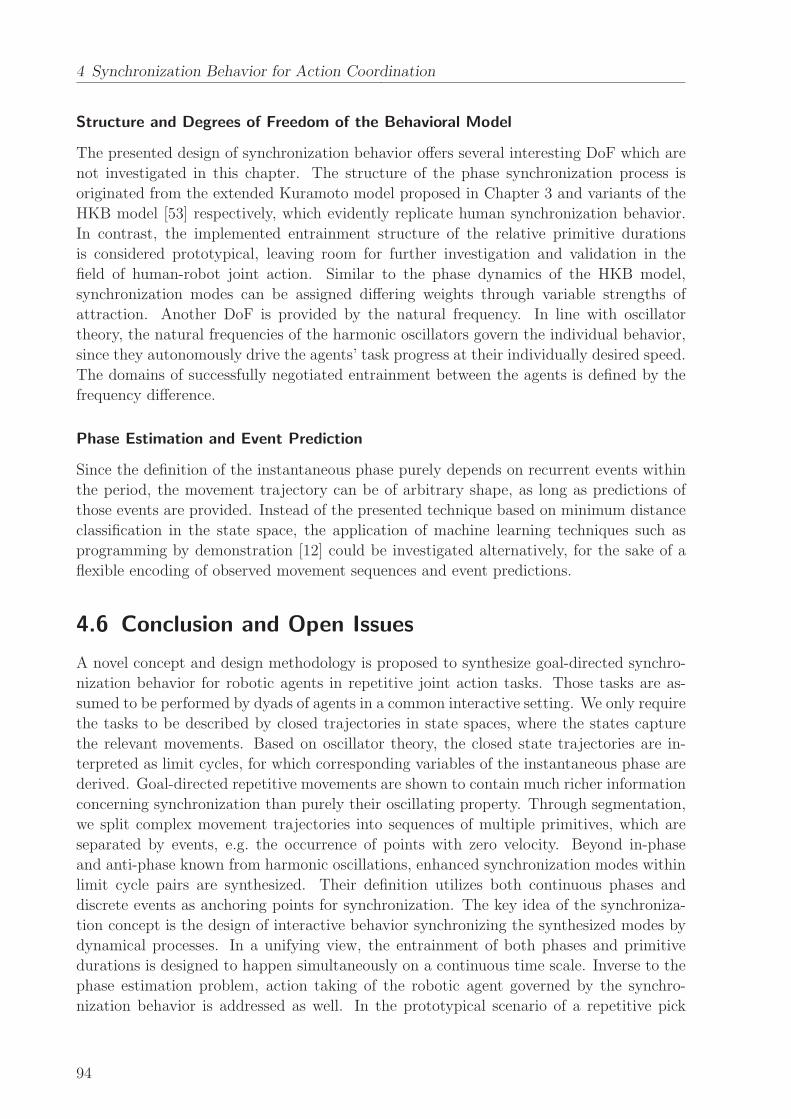
4 Synchronization Behavior for Action Coordination
Structure and Degrees of Freedom of the Behavioral Model
The presented design of synchronization behavior offers several interesting DoF which are
not investigated in this chapter. The structure of the phase synchronization process is
originated from the extended Kuramoto model proposed in Chapter 3 and variants of the
HKB model [53] respectively, which evidently replicate human synchronization behavior.
In contrast, the implemented entrainment structure of the relative primitive durations
is considered prototypical, leaving room for further investigation and validation in the
field of human-robot joint action. Similar to the phase dynamics of the HKB model,
synchronization modes can be assigned differing weights through variable strengths of
attraction. Another DoF is provided by the natural frequency. In line with oscillator
theory, the natural frequencies of the harmonic oscillators govern the individual behavior,
since they autonomously drive the agents’ task progress at their individually desired speed.
The domains of successfully negotiated entrainment between the agents is defined by the
frequency difference.
Phase Estimation and Event Prediction
Since the definition of the instantaneous phase purely depends on recurrent events within
the period, the movement trajectory can be of arbitrary shape, as long as predictions of
those events are provided. Instead of the presented technique based on minimum distance
classification in the state space, the application of machine learning techniques such as
programming by demonstration [12] could be investigated alternatively, for the sake of a
flexible encoding of observed movement sequences and event predictions.
4.6 Conclusion and Open Issues
A novel concept and design methodology is proposed to synthesize goal-directed synchro-
nization behavior for robotic agents in repetitive joint action tasks. Those tasks are as-
sumed to be performed by dyads of agents in a common interactive setting. We only require
the tasks to be described by closed trajectories in state spaces, where the states capture
the relevant movements. Based on oscillator theory, the closed state trajectories are in-
terpreted as limit cycles, for which corresponding variables of the instantaneous phase are
derived. Goal-directed repetitive movements are shown to contain much richer information
concerning synchronization than purely their oscillating property. Through segmentation,
we split complex movement trajectories into sequences of multiple primitives, which are
separated by events, e.g. the occurrence of points with zero velocity. Beyond in-phase
and anti-phase known from harmonic oscillations, enhanced synchronization modes within
limit cycle pairs are synthesized. Their definition utilizes both continuous phases and
discrete events as anchoring points for synchronization. The key idea of the synchroniza-
tion concept is the design of interactive behavior synchronizing the synthesized modes by
dynamical processes. In a unifying view, the entrainment of both phases and primitive
durations is designed to happen simultaneously on a continuous time scale. Inverse to the
phase estimation problem, action taking of the robotic agent governed by the synchro-
nization behavior is addressed as well. In the prototypical scenario of a repetitive pick
94
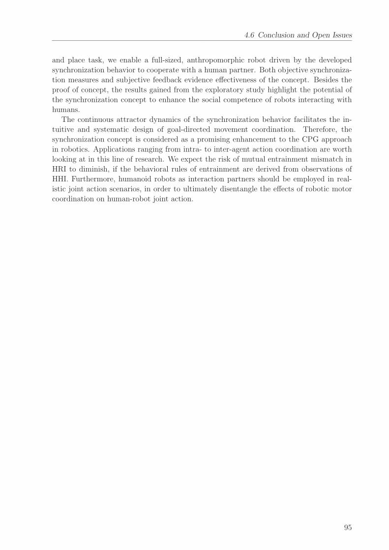
4.6 Conclusion and Open Issues
and place task, we enable a full-sized, anthropomorphic robot driven by the developed
synchronization behavior to cooperate with a human partner. Both objective synchroniza-
tion measures and subjective feedback evidence effectiveness of the concept. Besides the
proof of concept, the results gained from the exploratory study highlight the potential of
the synchronization concept to enhance the social competence of robots interacting with
humans.
The continuous attractor dynamics of the synchronization behavior facilitates the in-
tuitive and systematic design of goal-directed movement coordination. Therefore, the
synchronization concept is considered as a promising enhancement to the CPG approach
in robotics. Applications ranging from intra- to inter-agent action coordination are worth
looking at in this line of research. We expect the risk of mutual entrainment mismatch in
HRI to diminish, if the behavioral rules of entrainment are derived from observations of
HHI. Furthermore, humanoid robots as interaction partners should be employed in real-
istic joint action scenarios, in order to ultimately disentangle the effects of robotic motor
coordination on human-robot joint action.
95
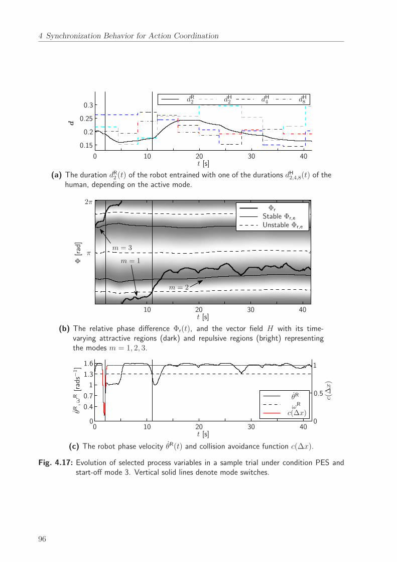
4 Synchronization Behavior for Action Coordination
d
dR2 dH2 dH4 dH8
t [s]0 10 20 30 40
0.15
0.2
0.25
0.3
(a) The duration dR2 (t) of the robot entrained with one of the durations dH2,4,8(t) of thehuman, depending on the active mode.
π
2π
t [s]
Φ[rad]
Φr
Stable Φr,e
Unstable Φr,e
m = 1
m = 2
m = 3
10 20 30 40
(b) The relative phase difference Φr(t), and the vector field H with its time-varying attractive regions (dark) and repulsive regions (bright) representingthe modes m = 1, 2, 3.
t [s]
θR,ω
R[rads−
1]
c(∆x)
c(∆x)
θR
ωR
000 10 20 30 40
0.4
0.50.7
1
1
1.3
1.6
(c) The robot phase velocity θR(t) and collision avoidance function c(∆x).
Fig. 4.17: Evolution of selected process variables in a sample trial under condition PES andstart-off mode 3. Vertical solid lines denote mode switches.
96
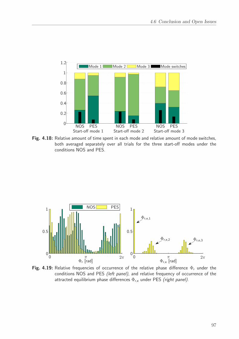
4.6 Conclusion and Open Issues
Mode 1 Mode 2 Mode 3 Mode switches
NOSNOSNOS PESPESPESStart-off mode 1 Start-off mode 2 Start-off mode 3
0
0.2
0.4
0.6
0.8
1
1.2
Fig. 4.18: Relative amount of time spent in each mode and relative amount of mode switches,both averaged separately over all trials for the three start-off modes under theconditions NOS and PES.
Φr [rad] Φr,e [rad]
NOS PES
ππ 2π2π00
00
0.50.5
11
Φr,e,1
Φr,e,2 Φr,e,3
Fig. 4.19: Relative frequencies of occurrence of the relative phase difference Φr under theconditions NOS and PES (left panel), and relative frequency of occurrence of theattracted equilibrium phase differences Φr,e under PES (right panel).
97
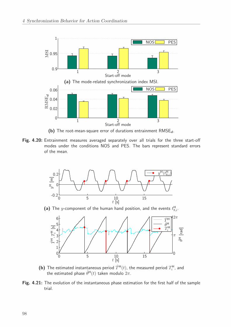
4 Synchronization Behavior for Action Coordination
NOS PES
Start-off mode
MSI
0.9
0.95
1
1 2 3
(a) The mode-related synchronization index MSI.
NOS PES
Start-off mode
RMSEd
0.02
0.04
0.06
01 2 3
(b) The root-mean-square error of durations entrainment RMSEd.
Fig. 4.20: Entrainment measures averaged separately over all trials for the three start-offmodes under the conditions NOS and PES. The bars represent standard errorsof the mean.
yH[m
]
t [s]
yH(tH8,i)
0
0 5 10 15
0.2
-0.2
(a) The y-component of the human hand position, and the events tH8,i.
TH,T
H i[s]
t [s]
θH[rad]
TH
θH
THi
π
2π
000 10 15
1
2
3
4
5
5
6
(b) The estimated instantaneous period TH(t), the measured period THi , and
the estimated phase θH(t) taken modulo 2π.
Fig. 4.21: The evolution of the instantaneous phase estimation for the first half of the sampletrial.
98

5 Role Behavior for Physical Cooperation
The transport of a heavy and bulky object is a popular example that highlights the need
for cooperative manipulation performed by two or more partners, in order to share the
physical load and achieve commonly desired goal configurations of the object. Employing
robots as assistants or partners in various kinds of haptic joint action tasks is an appealing
prospect to disburden and safe human workforce. The twofold feature of haptic interaction
during physical cooperation is particularly challenging. Physical coupling allows human
partners to bidirectionally negotiate and accomplish the joint action task through the same
modality. Additionally, the strong implicit nature of the haptic communication channel
requires sophisticated interpretive capabilities to understand the partners’ behavior on
a fast time scale. One key point to be negotiated is the necessary effort to accomplish
cooperative physical tasks. Observable effects of human negotiation in such tasks are
emerging strategies in terms of temporally consistent haptic interaction patterns, found
by Reed et al. [134] and called specialization. These patterns refer to a self-organized
distribution of the agents’ individual contributions. Forming patterns of interaction seems
to ease mutual understanding of the partners, as improved task performance has been
observed repeatedly in cooperative settings [34, 133].
As soon as autonomous physical assistants are able to produce their own goal-directed
behavior, the question of interactive role allocation arises similarly. Motion planning tech-
niques can be used to calculate the necessary force contribution of the robot towards the
task goals. However, the assignment and possible re-allocation of roles can evolve dy-
namically during task execution, and therefore cannot be precomputed. This results in
the challenge of synthesizing interactive behavior, that takes the human habit to establish
and dynamically change roles into account, and renders an intuitive interaction to the
human partner. A deep understanding of the physical meaning of roles in human-robot
cooperative manipulation is believed to be indispensable to develop human-centered role
behavior for physical assistant robots. Through system-theoretic modeling of the cooper-
ative manipulation problem, we explicitly investigate input redundancies arising from the
geometrical properties of non-point mass objects, which is novel in the context of pHRI.
The cooperative task is decomposed into redundant and non-redundant DoF. Meaningful
effort sharing policies in the redundant DoF are derived, that allow to render static role
behavior of robotic partners. On top of those, a set of strategies for dynamic role allo-
cation based on human haptic feedback is developed in a synthetical design perspective.
The extensive experimental evaluation of prototypical role allocation schemes in a realistic
and immersive full-scale scenario allows to gain unique insights on interactive role behav-
ior, that go beyond state-of-the-art VR studies. While quantitative task performance is
improved significantly by continuously changing roles, a constant role allocation achieves
best subjective ratings.
This chapter is organized as follows: In Section 5.1 we provide an overview on the
99
5 Role Behavior for Physical Cooperation
research history towards physical robot assistance and recent advances on incorporating
human behaviors and role allocations. Similarities and differences with respect to the field
of haptic shared control are discussed as well. The system-theoretic modeling concept is
introduced in Section 5.2, along with the decomposition approach leading to efficient effort
sharing policies within cooperating dyads. In Section 5.3 the interaction control scheme is
developed, which embeds the effort sharing strategy. Rendered static role behavior is both
analytically and experimentally characterized. After a discussion of distinct adjustment
criteria and policies, we synthesize two dynamic role allocation schemes in Section 5.4. The
experimental study and evaluation of dynamic role behavior with a real robotic partner is
presented in Section 5.5. Finally, in Section 5.6, we draw the conclusion on role behavior
design from a synthetical perspective, and highlight some discovered points for future
research.
5.1 Background
Related existing approaches towards physical robotic helpers are often restricted to smooth
and intuitive, yet reactive behavior of robots in physical interaction with humans rather
than situation-dependent active task contribution. Starting from the last decade, advances
in human behavior research and modeling facilitates the design of actively contributing
partners capable of pHRI tasks. While some works investigate leader-follower schemes
to render interactive robot behavior, to date, only little research is devoted to the topic
of dynamic role allocation between human and robotic partners. Therefore, we review
approaches from the related field of haptic shared control as well.
5.1.1 Physical Robotic Assistance
Starting Out with Purely Reactive Behavior
The synthesis of robotic assistants for cooperative load sharing tasks reaches back to the
early 1990’s when [81] deploy an object-centered impedance control scheme similar to [154]
for a set of robots cooperating with a number of humans. Successful robot implementations
named MR Helper [82] and the distributed variant DR Helpers [59] encourage research
groups to work on synthesis methods for cooperative human-robot object manipulation
strategies. An overview of the achievements of Hirata and Kosuge in this field is given
in [80]. The application of cooperative load transport is also targeted by Gillespie et al.
[42] using the rather different cobot approach. While robotic helpers actively render a
virtual object impedance behavior with features such as collision avoidance, cobots cannot
move on their own—they are inherently passive. However, motion induced by a human
operator is projected along virtual curvatures by arranging counter-acting forces in the
cobots. This approach focuses on desired paths or workspace constraints rather than de-
sired virtual dynamic object behavior. Similarly, the concept of virtual fixtures introduced
by Rosenberg [141] defines overlays such as virtual rulers guiding the operator’s effector
motion in telepresence setups. An approach combining desired virtual constraints and
desired virtual object dynamics is proposed in [165]. In their work, a robotic partner ren-
ders a virtual nonholonomic constraint—namely a virtual wheel—that prohibits sideway
100
5.1 Background
slipping motion and thus simplifies operation similar to a wheelbarrow. This simplifica-
tion however, inhibits maneuvering of bulky objects in narrow passages. Representing a
dynamic pHRI task, cooperative rope turning is investigated by [77, 98]. Based on rhythm
entrainment and controlled energy transfer, stable rope turning with a human partner
is realized. Yet, even in the more recent work [77], the human is still in charge of the
swing-up phase, until a stable rope turning motion is achieved by the robot. All of these
approaches consider robotic partners that follow and react to user operation, which limits
their capabilities to gravity compensation or collision avoidance when maneuvering heavy
or bulky loads.
Exploring and Incorporating Human Interactive Behavior
A deep understanding of human interactive behavior is considered essential to render nat-
ural interaction strategies for physical cooperation between humans and robots. Several
approaches target efficient physical interaction by rendering human-oriented feedback be-
havior of reactive robots. The group of Ikeura investigates the feedback behavior of a
following manipulator during cooperative object transport. Human impedance character-
istics are found to be superior in terms of subjective scores [67] and enable natural move-
ment profiles [68]. Going further, Tsumugiwa et al. [172] show an improved performance
in a cooperative calligrahic task, when the feedback control of the robot is adapted on-line
with respect to the estimated human feedback behavior. In a similar setting, the derivative
of the human force feedback is interpreted as an indicator of the human intention, and the
damping parameter of the robot controller is adapted accordingly [28]. In order to over-
come the limitations of purely reactive assistance behavior, active task contribution of a
robot partner needs to respect human intentions. A significant body of work is dedicated to
fundamental modeling of human behavior in cooperative haptic tasks, or to transfer find-
ings from HHI to cooperative robotic partners. The popular concept of jerk minimization
in human arm movements found by Flash and Hogan [36] for point-to-point movements is
transferred to cooperative manipulation in [97] and later also in [20]. It enables a robotic
partner to not just react to the human operator input, but also to predict human intentions
in terms of the movement goal and duration, and to assist accordingly. Corteville et al.
[20] emphasize the resulting bell-shaped velocity profile as well as an adjustable degree
of assistance to be vital to natural cooperation. In a human-human cooperative object
transfer task, Miossec and Kheddar [108] later discover a variant of the minimum-jerk
model to fit best the observed movement profiles. Reed and colleagues observe temporally
consistent behavior patterns during human-human physical cooperation [133, 134]. The
authors call this phenomenon specialization. In a Turing test, they successfully transfer
their results to a human-robot setup such that participants can not distinguish between
the robotic partner and an actual human partner, yet the human specialization effect can
not be reproduced [132]. Their findings on evolving specialization are further investigated
in [48]. Humans are shown to prefer a certain dominance difference among collaborating
partners in contrast to equally shared control. In this context, (physical) dominance refers
to the actual achievement of influence or control over another and therefore reflects the
individual share of the overall contribution to task success. In particular, effort distri-
butions appear to be partly person-specific and partly interaction-dependent, and thus,
101
5 Role Behavior for Physical Cooperation
time-varying. Human following behavior in response to a leading robotic manipulator is
investigated in a cooperative vertical lifting task in [118]. Behavioral hallmarks, such as
different, modality-related frequency domains of human response are discovered, with the
goal of synthesizing human-like interaction controllers. Similar to the object-lifting ap-
proach in [82] and based on observed criteria of human response behavior, corresponding
robot follower controllers are synthesized guided by human preferences [119].
Leader-Follower and Role Allocation Schemes
A controller blending scheme that allows the allocation of leader and follower roles by
independent blending variables is proposed by Evrard and Kheddar [31]. While homotopy
blending of two extreme controllers for each agent is a very generic approach accounting
for a variety of interaction behaviors, the functional modeling how to adjust the blending
parameter remains an open issue. Based on the movement model of [108], the controller
blending scheme is capable of reproducing the phenomenon of specialization in simulation,
as well as smooth self-collision avoidance of a humanoid robot [32]. Recent thoughts from
this group on the leader-follower assignment problem are found in [76]. In particular, it
is indicated that blending of stable leader and follower controllers will not necessarily re-
sult in a stable overall behavior. An overall system architecture implemented on a small
scale humanoid robot that comprises a confidence-based role adaptation using homotopy
blending is presented in [169]. The blending variable is drawn from state estimation of a
human motion model, which is interpreted as confidence. An emerging interest in smart
physical robotic assistants for human workers in industrial settings is visible since a few
years. Basic physical assistance for the well defined task of precise positioning of wind-
shields during car manufacturing processes is developed in [189]. Their framework proposes
a strict geometrical separation of the DoF and weighs the assisting force contribution to
the task according to defined haptic cues. The theory of risk-sensitive optimal feedback
control is applied to the haptic assistance problem by Medina et al. [104]. Employing a
probabilistic model of the human task-related behavior, the authors are able to render a
meaningful, confidence-based role allocation behavior, based on the predicted variabilities
of both human movements and force contributions. Moreover, different characteristics (at-
titudes) of the role allocation are representable within the risk-sensitivity framework, i.e.
human force variabilities interpreted as unexpected behavior are handled in a more or less
dominant way. Later, the authors modify their approach to reflect both current and pre-
dicted variabilities of the human contribution [105] through on-line noise estimation. By
interpreting the current force variabilities as the current level of human disagreement, an
enhanced interaction performance in a cooperative object transport task through a virtual
maze is achieved. The choice of the risk-sensitivity parameter is considered as attitude de-
sign problem in [144]. A functional dependency of the parameter composed by two factors
is proposed, integrating both an adaptation to diverging noise levels and environmental
constraints. The role assignment problem arising in human-robot joint action is thoroughly
reviewed by Jarrasse et al. [70], considering both psychological studies of HHI and related
works in pHRI.
102
5.1 Background
5.1.2 Relation to Haptic Shared Control
The research field of haptic shared control is mostly directed towards assistance and hap-
tic guidance of humans in controlling machines, e.g. vehicular control [46], but also in
virtual environment tasks [113, 116] and in tele-operation scenarios [121]. The control
input of the virtual assistant is usually rendered as an additive force superposed to the
human control input. Smooth changes of the degree of assistance allow to implement con-
tinuously changing levels of automation. Applications and design guidelines for systems
incorporating haptic shared control are comprehensively discussed in [1]. Shared control
of an admittance-controlled mobility aid for elderly people is proposed in [191]. Homotopy
blending between the force inputs of the human and the virtual assistant smoothly shifts
the control authority of the vehicle, depending on the on-line evaluation of a multi-criterion
performance index. Blending between a number of finite control states (user dominant,
equal control and blending) in a dynamic virtual task is proposed in the haptic negotiation
framework of Oguz et al. [113]. During the cooperative solving of a haptic board game,
their system realizes dynamic role exchange by granting control to the virtual partner or
the operator regarding human intentions through an adjustment of both partners’ coupling
stiffnesses. The human operator is assumed to display the intention of gaining control by
applying large forces to the system compared to known force profiles. Later, Kucuky-
ilmaz et al. [86] show that this dynamic role exchange scheme improves task efficiency
significantly compared to an equal control guidance scheme, and that it constitutes a per-
sonal and subjectively pleasing interaction model. Notably, this framework is targeted
to human-computer interaction (HCI) scenarios, since both the coupling of the virtual
assistant and the human operator are adjusted. Recently, dynamically changing levels
of haptic assistance that depend on single or multi-criterion measures of performance are
postulated by Passenberg et al. [123]. The authors propose a rigorous assistance taxonomy
regarding the reference of performance measures, which may be internal or external, and
the adaptation characteristics of the assistance policy, which may be constant, continuous
or discretely switching. In a haptic shared-control scenario, different implementations of
the performance reference and the assistance policy are compared regarding their overall
performance and perceived workload. Results from the study render adaptive assistance
policies combined with multi-criterion performance measures to be beneficial. Despite
many inspiring affinities between related works in the field of haptic shared control and
the role allocation problem for physical cooperation, some important differences emerge
from the interaction of the physically coupled entities, i.e. the human, the robotic partner
and the cooperatively manipulated object:
• In virtual environment and tele-operation scenarios, shared control approaches may
rely on the possibility to adjust the coupling between the human operator and the
jointly manipulated object. In contrast, during physical robotic assistance, the poten-
tially varying coupling and control input of the human partner cannot be controlled,
but only observed or inferred.
• Haptic shared control schemes usually assume collocation of the partners’ control
inputs, i.e. the operator and the virtual assistant are directly coupled, both acting on
one control interface. In contrast, cooperative object manipulation in pHRI usually
103

5 Role Behavior for Physical Cooperation
−1
(+
−1
(+
)
)
Common plan(a)
(a)
(d)
(c)
(c)
(b)
(b) Agent 1
Agent 2
Effort-rolebehavior
Effort-rolebehavior
WrenchMotion
MIN
MIN
MAX
MAX
Fig. 5.1: Conceptual overview: Two agents cooperatively manipulates a common object ac-cording to a shared plan. Both agents employ an inverse object model and impedancecontrol loop (a) generating desired object-centered wrenches (b). The effort-role be-havior determines the control inputs applied at the agents’ grasp points (c), whichcompose the object-centered wrench (d) required for configuration tracking of theobject. Later, a scheme to allocate the agents’ roles based on mutual feedback ofthe control inputs will be developed.
involves a time-varying coupling between the partners, mediated by the physical
properties of the object, i.e. its geometry and dynamics.
5.2 Physical Effort Sharing in Cooperative Manipulation
The cooperative task of jointly manipulating a rigid bulky object by human-robot teams
is addressed in the following. In contrast to state-of-the-art approaches restricted to the
cooperative manipulation of virtual point-mass objects or one common interaction point
respectively, we explicitly consider spatially distributed grasp points of the partners. The
effort sharing concept is developed based on the task representation in an object-centered
point of view.
5.2.1 Problem Formulation and Concept
Definition of the Effort Sharing Problem
The envisaged scenario facilitates the cooperation between a human and an assistive robot.
Cooperation is defined according to [115, 120] as the willing participation of all agents
towards a common goal along a shared plan. In line with this, we focus on manipulation
tasks which require physical cooperation between the partners through close coupling with
an object, see Figure 5.1. When two or more agents cooperate by jointly manipulating
a common object, the problem of sharing the physical effort of the task arises. The
physical coupling imposed by the geometrical and dynamical properties of the task has
to be addressed and exploited such that each agent’s effort in terms of input wrenches
allow for a smooth and efficient cooperation. We confine the effort sharing problem to the
following conditions:
104

5.2 Physical Effort Sharing in Cooperative Manipulation
• One human cooperates with one robot or alternatively, a system of robots with cen-
tralized communication towards achieving a common known goal, e.g. reaching cer-
tain object configuration(s) when jointly manipulating an object.
• Constraints of the environment are such that the task is achievable, i.e. a feasible
path to the goal exists.
• All participants tightly grasp a single rigid object with commonly known shape and
dynamics.
• Object dynamics are holonomic, i.e. the manipulated system does not have any
velocity-dependent constraints. Concretely, such a system can be accelerated in
arbitrary direction of the configuration space.
• The grasp points are such that the task is controllable and its control inputs are
redundant. Therefore, we require at least the same number of non-redundant control
inputs as corresponding configuration variables [19, 195].
• The partners interact with each other only through the haptic channel provided
by the physical coupling. Other forms of communication, e.g. speech or gestures,
are beyond the scope of this work. We believe that the interaction via the haptic
modality needs to be understood profoundly, before other modalities are added.
System-Theoretic Modeling Concept
Dynamic modeling is performed to capture the physical and geometrical properties of the
manipulation task under environmental constraints. Specifically, we model the dynamics
of the manipulated object including the agents’ contact points, see Figure 5.1. Adopting an
object-centered point of view, the agents’ contributions to the task are defined by spatially
distributed control inputs, i.e. the forces that affect the object motion towards the goal.
Research on human cooperation strategies suggest an object-centered formulation of the
desired path. Human dyads are found to achieve better tracking performance in a coop-
erative task, when they have common visual access to the central part of the manipulated
object [146]. Thus, the desired motion of the manipulated object is intuitively represented
by an object-centered trajectory, which is considered to result from an a priori negotiation
between the agents. In this work, we assume shared goals in terms of known intermedi-
ate configurations of the manipulated object. Trajectories for the cooperating dyad can
be precomputed by the robot through planning techniques as proposed in [78], following
human-inspired optimality criteria such as the least-action principle [89], or through prob-
abilistic encoding and reproduction of human demonstrations [90, 199]. Recently, even
fusion strategies of both learning and planning are investigated regarding their synergetic
potentials in the context of trajectory generation in cooperative pHRI [88].
Impedance control loops closed on motion feedback are employed by each agent and
ensure compliant tracking of the desired object trajectory. The human motor control
system is known to accomplish haptic tasks by a combination of impedance control and
inverse dynamics of the task, see e.g. [38]. As the object model is assumed to be commonly
known, each agent is able to apply an inverse dynamics model of the object, in order to
105
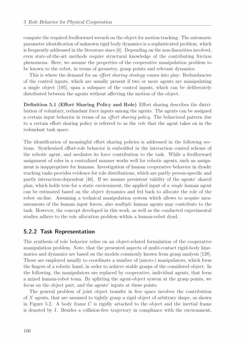
5 Role Behavior for Physical Cooperation
compute the required feedforward wrench on the object for motion tracking. The automatic
parameter identification of unknown rigid body dynamics is a sophisticated problem, which
is frequently addressed in the literature since [6]. Depending on the non-linearities involved,
even state-of-the-art methods require structural knowledge of the contributing friction
phenomena. Here, we assume the properties of the cooperative manipulation problem to
be known to the robot, in terms of geometry, grasp points and relevant dynamics.
This is where the demand for an effort sharing strategy comes into play: Redundancies
of the control inputs, which are usually present if two or more agents are manipulating
a single object [195], span a subspace of the control inputs, which can be deliberately
distributed between the agents without affecting the motion of the object.
Definition 5.1 (Effort Sharing Policy and Role) Effort sharing describes the distri-
bution of voluntary, redundant force inputs among the agents. The agents can be assigned
a certain input behavior in terms of an effort sharing policy. The behavioral pattern due
to a certain effort sharing policy is referred to as the role that the agent takes on in the
redundant task space.
The identification of meaningful effort sharing policies is addressed in the following sec-
tions. Synthesized effort-role behavior is embedded in the interaction control scheme of
the robotic agent, and mediates its force contribution to the task. While a feedforward
assignment of roles in a centralized manner works well for robotic agents, such an assign-
ment is inappropriate for humans. Investigation of human cooperative behavior in dyadic
tracking tasks provides evidence for role distributions, which are partly person-specific and
partly interaction-dependent [48]. If we assume persistent validity of the agents’ shared
plan, which holds true for a static environment, the applied input of a single human agent
can be estimated based on the object dynamics and fed back to allocate the role of the
robot on-line. Assuming a technical manipulation system which allows to acquire mea-
surements of the human input forces, also multiple human agents may contribute to the
task. However, the concept developed in this work, as well as the conducted experimental
studies adhere to the role allocation problem within a human-robot dyad.
5.2.2 Task Representation
The synthesis of role behavior relies on an object-related formulation of the cooperative
manipulation problem. Note, that the presented aspects of multi-contact rigid-body kine-
matics and dynamics are based on the models commonly known from grasp analysis [128].
Those are employed usually to coordinate a number of (micro-) manipulators, which form
the fingers of a robotic hand, in order to achieve stable grasps of the considered object. In
the following, the manipulators are replaced by cooperative, individual agents, that form
a mixed human-robot team. By splitting the agent-object system at the grasp points, we
focus on the object part, and the agents’ inputs at these points.
The general problem of joint object transfer in free space involves the contribution
of N agents, that are assumed to tightly grasp a rigid object of arbitrary shape, as shown
in Figure 5.2. A body frame C is rigidly attached to the object and the inertial frame
is denoted by I. Besides a collision-free trajectory in compliance with the environment,
106
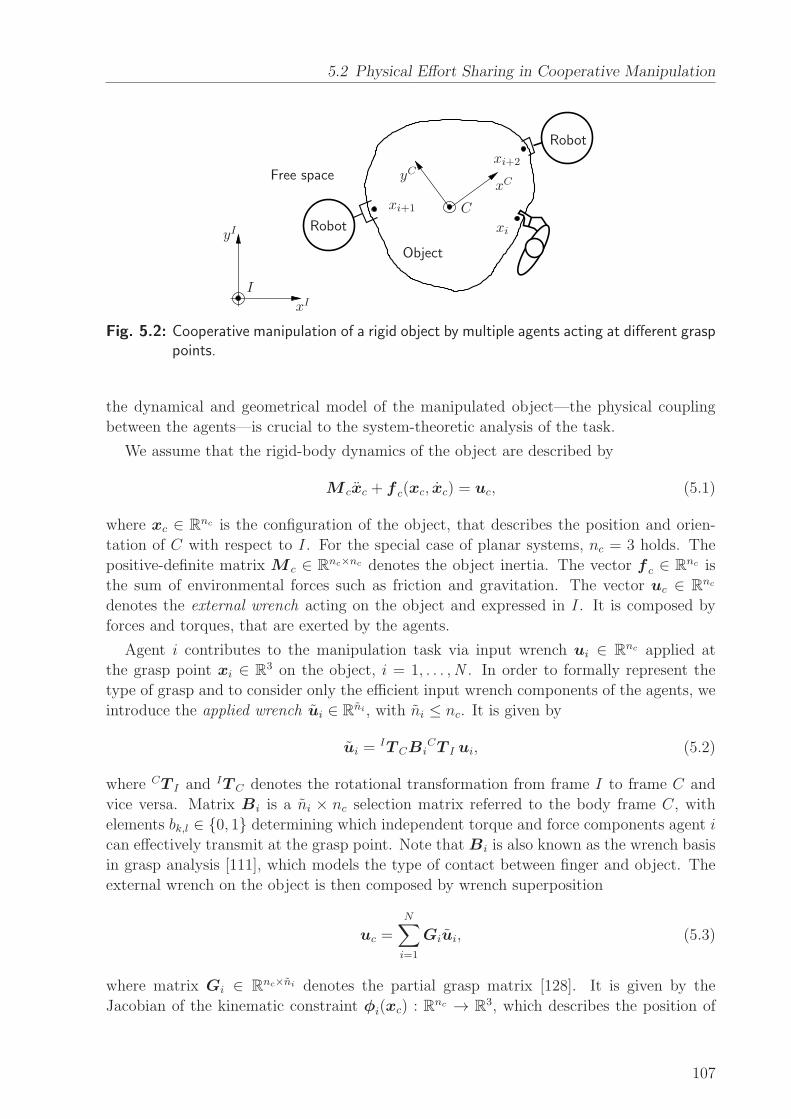
5.2 Physical Effort Sharing in Cooperative Manipulation
xI
yI
xCyCFree space
Object
Robot
Robot
I
Cxi+1
xi
xi+2
Fig. 5.2: Cooperative manipulation of a rigid object by multiple agents acting at different grasppoints.
the dynamical and geometrical model of the manipulated object—the physical coupling
between the agents—is crucial to the system-theoretic analysis of the task.
We assume that the rigid-body dynamics of the object are described by
M cxc + f c(xc, xc) = uc, (5.1)
where xc ∈ Rnc is the configuration of the object, that describes the position and orien-
tation of C with respect to I. For the special case of planar systems, nc = 3 holds. The
positive-definite matrix M c ∈ Rnc×nc denotes the object inertia. The vector f c ∈ R
nc is
the sum of environmental forces such as friction and gravitation. The vector uc ∈ Rnc
denotes the external wrench acting on the object and expressed in I. It is composed by
forces and torques, that are exerted by the agents.
Agent i contributes to the manipulation task via input wrench ui ∈ Rnc applied at
the grasp point xi ∈ R3 on the object, i = 1, . . . ,N . In order to formally represent the
type of grasp and to consider only the efficient input wrench components of the agents, we
introduce the applied wrench ui ∈ Rni , with ni ≤ nc. It is given by
ui =IT CBi
CT I ui, (5.2)
where CT I and IT C denotes the rotational transformation from frame I to frame C and
vice versa. Matrix Bi is a ni × nc selection matrix referred to the body frame C, with
elements bk,l ∈ {0, 1} determining which independent torque and force components agent i
can effectively transmit at the grasp point. Note that Bi is also known as the wrench basis
in grasp analysis [111], which models the type of contact between finger and object. The
external wrench on the object is then composed by wrench superposition
uc =N∑
i=1
Giui, (5.3)
where matrix Gi ∈ Rnc×ni denotes the partial grasp matrix [128]. It is given by the
Jacobian of the kinematic constraint φi(xc) : Rnc → R3, which describes the position of
107
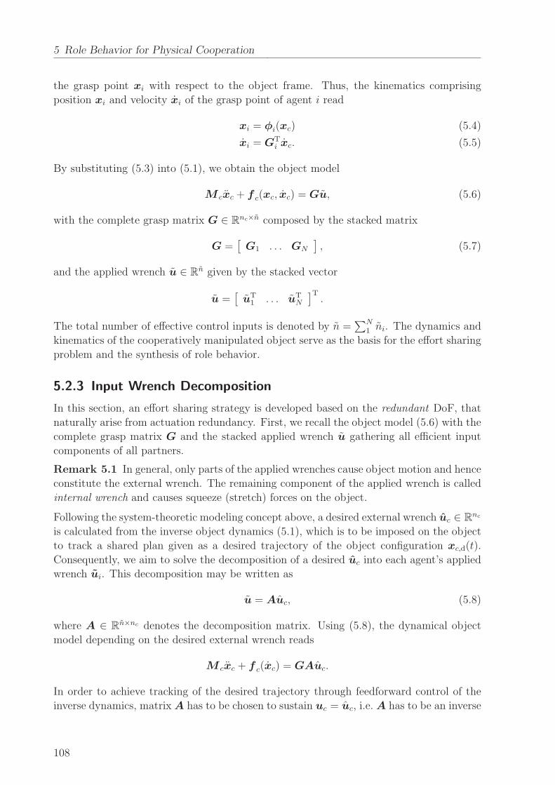
5 Role Behavior for Physical Cooperation
the grasp point xi with respect to the object frame. Thus, the kinematics comprising
position xi and velocity xi of the grasp point of agent i read
xi = φi(xc) (5.4)
xi = GTi xc. (5.5)
By substituting (5.3) into (5.1), we obtain the object model
M cxc + f c(xc, xc) = Gu, (5.6)
with the complete grasp matrix G ∈ Rnc×n composed by the stacked matrix
G =[
G1 . . . GN
]
, (5.7)
and the applied wrench u ∈ Rn given by the stacked vector
u =[
uT1 . . . uT
N
]T.
The total number of effective control inputs is denoted by n =∑N
1 ni. The dynamics and
kinematics of the cooperatively manipulated object serve as the basis for the effort sharing
problem and the synthesis of role behavior.
5.2.3 Input Wrench Decomposition
In this section, an effort sharing strategy is developed based on the redundant DoF, that
naturally arise from actuation redundancy. First, we recall the object model (5.6) with the
complete grasp matrix G and the stacked applied wrench u gathering all efficient input
components of all partners.
Remark 5.1 In general, only parts of the applied wrenches cause object motion and hence
constitute the external wrench. The remaining component of the applied wrench is called
internal wrench and causes squeeze (stretch) forces on the object.
Following the system-theoretic modeling concept above, a desired external wrench uc ∈ Rnc
is calculated from the inverse object dynamics (5.1), which is to be imposed on the object
to track a shared plan given as a desired trajectory of the object configuration xc,d(t).
Consequently, we aim to solve the decomposition of a desired uc into each agent’s applied
wrench ui. This decomposition may be written as
u = Auc, (5.8)
where A ∈ Rn×nc denotes the decomposition matrix. Using (5.8), the dynamical object
model depending on the desired external wrench reads
M cxc + f c(xc) = GAuc.
In order to achieve tracking of the desired trajectory through feedforward control of the
inverse dynamics, matrix A has to be chosen to sustain uc = uc, i.e. A has to be an inverse
108
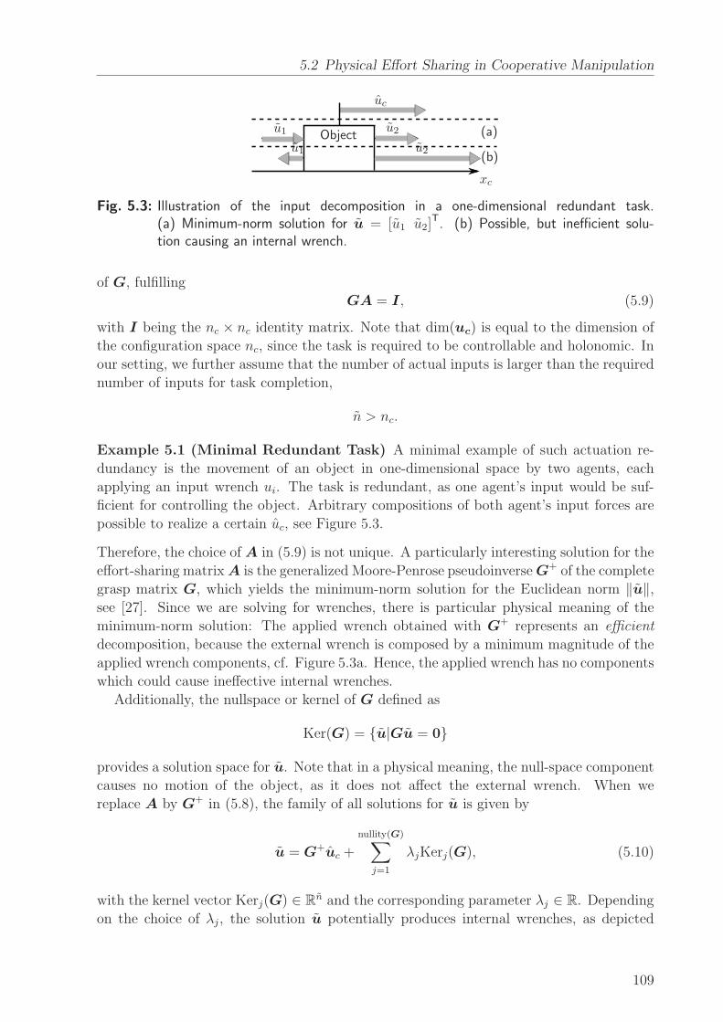
5.2 Physical Effort Sharing in Cooperative Manipulation
(a)
(b)
xc
uc
u1
u1
u2
u2Object
Fig. 5.3: Illustration of the input decomposition in a one-dimensional redundant task.(a) Minimum-norm solution for u = [u1 u2]
T. (b) Possible, but inefficient solu-tion causing an internal wrench.
of G, fulfilling
GA = I, (5.9)
with I being the nc × nc identity matrix. Note that dim(uc) is equal to the dimension of
the configuration space nc, since the task is required to be controllable and holonomic. In
our setting, we further assume that the number of actual inputs is larger than the required
number of inputs for task completion,
n > nc.
Example 5.1 (Minimal Redundant Task) A minimal example of such actuation re-
dundancy is the movement of an object in one-dimensional space by two agents, each
applying an input wrench ui. The task is redundant, as one agent’s input would be suf-
ficient for controlling the object. Arbitrary compositions of both agent’s input forces are
possible to realize a certain uc, see Figure 5.3.
Therefore, the choice of A in (5.9) is not unique. A particularly interesting solution for the
effort-sharing matrixA is the generalized Moore-Penrose pseudoinverseG+ of the complete
grasp matrix G, which yields the minimum-norm solution for the Euclidean norm ‖u‖,see [27]. Since we are solving for wrenches, there is particular physical meaning of the
minimum-norm solution: The applied wrench obtained with G+ represents an efficient
decomposition, because the external wrench is composed by a minimum magnitude of the
applied wrench components, cf. Figure 5.3a. Hence, the applied wrench has no components
which could cause ineffective internal wrenches.
Additionally, the nullspace or kernel of G defined as
Ker(G) = {u|Gu = 0}
provides a solution space for u. Note that in a physical meaning, the null-space component
causes no motion of the object, as it does not affect the external wrench. When we
replace A by G+ in (5.8), the family of all solutions for u is given by
u = G+uc +
nullity(G)∑
j=1
λjKerj(G), (5.10)
with the kernel vector Kerj(G) ∈ Rn and the corresponding parameter λj ∈ R. Depending
on the choice of λj, the solution u potentially produces internal wrenches, as depicted
109

5 Role Behavior for Physical Cooperation
xI
yI
IxC
yCCu1,x
u1,y
u2,x
u2,y
x1 x2
Fig. 5.4: Illustrative scenario of planar cooperative manipulation: One human (left) and onerobot (right) jointly move a bulky object in the x-y-plane.
in Figure 5.3b. In fact, the solution (5.10) provides an effort sharing strategy by input
wrench decomposition: In redundant DoF where effort sharing between the agents can take
place and which are affected by λj, and in non-redundant DoF where each agent’s input
is uniquely defined by a necessary contribution. In the following, we show how λj can be
used to parameterize the effort sharing strategy between the agents in a single redundant
direction.
5.2.4 Effort Sharing Policies
In this section, we show how the agents can be assigned meaningful policies regarding their
effort behavior in a single redundant DoF. With reference to the experiments described
later and for intuitiveness of analysis, we consider from this section on a planar coopera-
tive manipulation task involving two agents for the design of effort sharing policies. The
presented strategy may be conducted in multiple redundant DoF without loss of generality.
Analysis of the Planar Dyadic Task
An exemplary planar dyadic task satisfying the conditions from Section 5.2.1 is shown in
Figure 5.4. The joint transport of a large table on ball casters, or the joint movement of any
other heavy object by sliding it on a surface can be such a task. Both, the human (i = 1)
and the robotic agent (i = 2) could provide input wrenches ui of dimension nc = 3, with
the configuration
xc =[
xc,φ xc,x xc,y]T,
which generally include torques. However, a common property of bulky objects regarding
their handling is the lack of sensitivity of the object dynamics to certain torque components,
i.e. these torques cannot be applied effectively at the grasp points, see also [189]. This can
be explained within our illustrative scenario. Assume a beam-like bulky object with a long
geometrical axis, which is manipulated by two partners using a single-handed grasp on the
respective end of the object, similar to the one depicted in Figure 5.4. In order to induce
a desired rotational motion around the zC-axis, from experience the reader might agree
that it is rather cumbersome to apply the required torque component through the wrist.
It is much easier to apply an appropriate force component through the whole arm, which
induces turning by translational motion of the grasp point.
Since our analysis focuses on the primary effects of the redundant DoF for effort sharing,
110
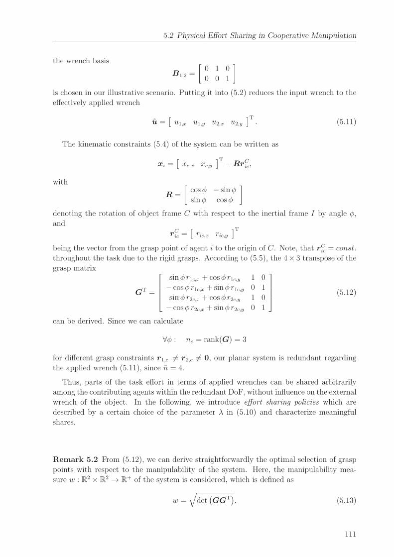
5.2 Physical Effort Sharing in Cooperative Manipulation
the wrench basis
B1,2 =
[
0 1 0
0 0 1
]
is chosen in our illustrative scenario. Putting it into (5.2) reduces the input wrench to the
effectively applied wrench
u =[
u1,x u1,y u2,x u2,y]T. (5.11)
The kinematic constraints (5.4) of the system can be written as
xi =[
xc,x xc,y]T −RrC
ic,
with
R =
[
cosφ − sinφ
sinφ cosφ
]
denoting the rotation of object frame C with respect to the inertial frame I by angle φ,
and
rCic =
[
ric,x ric,y]T
being the vector from the grasp point of agent i to the origin of C. Note, that rCic = const.
throughout the task due to the rigid grasps. According to (5.5), the 4× 3 transpose of the
grasp matrix
GT =
sinφ r1c,x + cosφ r1c,y 1 0
− cosφ r1c,x + sinφ r1c,y 0 1
sinφ r2c,x + cosφ r2c,y 1 0
− cosφ r2c,x + sinφ r2c,y 0 1
(5.12)
can be derived. Since we can calculate
∀φ : nc = rank(G) = 3
for different grasp constraints r1,c 6= r2,c 6= 0, our planar system is redundant regarding
the applied wrench (5.11), since n = 4.
Thus, parts of the task effort in terms of applied wrenches can be shared arbitrarily
among the contributing agents within the redundant DoF, without influence on the external
wrench of the object. In the following, we introduce effort sharing policies which are
described by a certain choice of the parameter λ in (5.10) and characterize meaningful
shares.
Remark 5.2 From (5.12), we can derive straightforwardly the optimal selection of grasp
points with respect to the manipulability of the system. Here, the manipulability mea-
sure w : R2 × R2 → R+ of the system is considered, which is defined as
w =√
det(
GGT)
. (5.13)
111

5 Role Behavior for Physical Cooperation
After straightforward calculation of (5.13) using (5.12), one finds
w =√2‖r1,c − r2,c‖.
Maximizing the value of w minimizes the applied wrenches at the grasp points for a given
external wrench uc by maximizing the eigenvalues in (5.3). This leads to the intuitive
result that the partners should grasp the object with maximum distance. Note that this
optimization is only valid for bounded ri,c and does not explicitly weigh angular vs. trans-
lational motion.
Identification of Meaningful and Efficient Policies
In a first step, we will investigate static sharing policies yielding constant role behaviors,
while in Section 5.4.2 our notion of roles will be extended to encompass a dynamic allo-
cation within dyads. In the given planar example, the only redundant DoF is intuitively
represented by the yC-axis of the object frame C, cf. Figure 5.4. Hence, components of
the external input wrench along this axis can be arbitrarily shared among the two agents.
Let us recall now the decomposition (5.10) leading to the agents’ applied wrench u. The
nullspace Ker(G) is spanned by the family
Ker(G) = diag (R,R) Ker(G)C , with
Ker(G)C =[
0 1 0 −1]T, (5.14)
allowing one DoF for the design of different effort sharing policies through the choice of
the scalar parameter λ in (5.10). Three extreme policies of particular physical meaning
are discussed below:
• Balanced-effort policy: By choosing the policy
πbal : λ = 0, (5.15)
the min-norm solution for u is obtained. The effort in terms of magnitude of the
applied wrench is equally shared among the agents, see Figure 5.5a.
• Maximum-robot-effort policy: If we want to have the robot to take over all of the
sharable effort, then the applied human force in the yC-direction would be zero,
i.e. uC1,y = 0. Hence, λ is chosen such that the human does not contribute any
voluntary effort to the task, which yields the policy
πmax : λ = −[
0 1 0 0]
uCbal, (5.16)
with the min-norm applied wrench
uCbal = diag (R,R)T G+uc. (5.17)
112
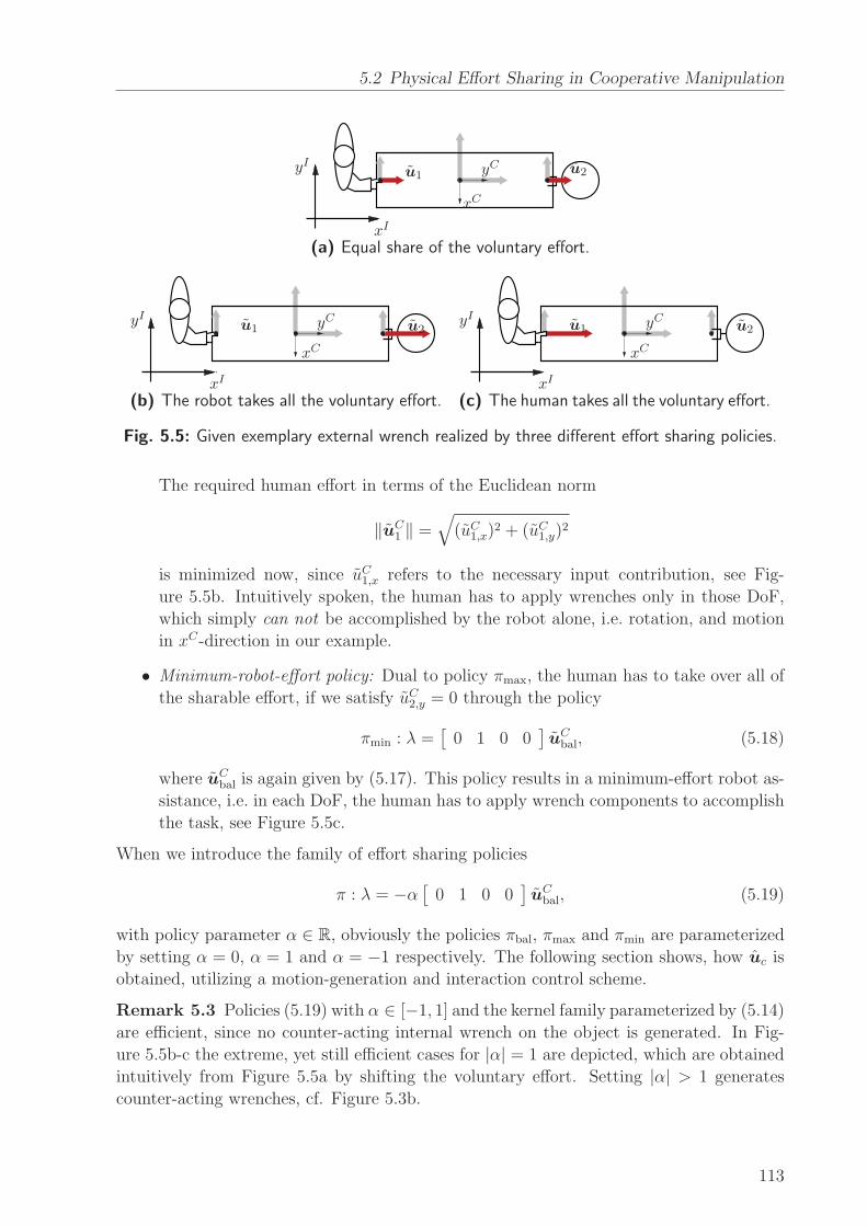
5.2 Physical Effort Sharing in Cooperative Manipulation
xI
yI u1
xC
yC u2
(a) Equal share of the voluntary effort.
xI
yI u1
xC
yC u2
(b) The robot takes all the voluntary effort.xI
yI u1
xC
yC u2
(c) The human takes all the voluntary effort.
Fig. 5.5: Given exemplary external wrench realized by three different effort sharing policies.
The required human effort in terms of the Euclidean norm
‖uC1 ‖ =
√
(uC1,x)2 + (uC1,y)
2
is minimized now, since uC1,x refers to the necessary input contribution, see Fig-
ure 5.5b. Intuitively spoken, the human has to apply wrenches only in those DoF,
which simply can not be accomplished by the robot alone, i.e. rotation, and motion
in xC-direction in our example.
• Minimum-robot-effort policy: Dual to policy πmax, the human has to take over all of
the sharable effort, if we satisfy uC2,y = 0 through the policy
πmin : λ =[
0 1 0 0]
uCbal, (5.18)
where uCbal is again given by (5.17). This policy results in a minimum-effort robot as-
sistance, i.e. in each DoF, the human has to apply wrench components to accomplish
the task, see Figure 5.5c.
When we introduce the family of effort sharing policies
π : λ = −α[
0 1 0 0]
uCbal, (5.19)
with policy parameter α ∈ R, obviously the policies πbal, πmax and πmin are parameterized
by setting α = 0, α = 1 and α = −1 respectively. The following section shows, how uc is
obtained, utilizing a motion-generation and interaction control scheme.
Remark 5.3 Policies (5.19) with α ∈ [−1, 1] and the kernel family parameterized by (5.14)
are efficient, since no counter-acting internal wrench on the object is generated. In Fig-
ure 5.5b-c the extreme, yet still efficient cases for |α| = 1 are depicted, which are obtained
intuitively from Figure 5.5a by shifting the voluntary effort. Setting |α| > 1 generates
counter-acting wrenches, cf. Figure 5.3b.
113
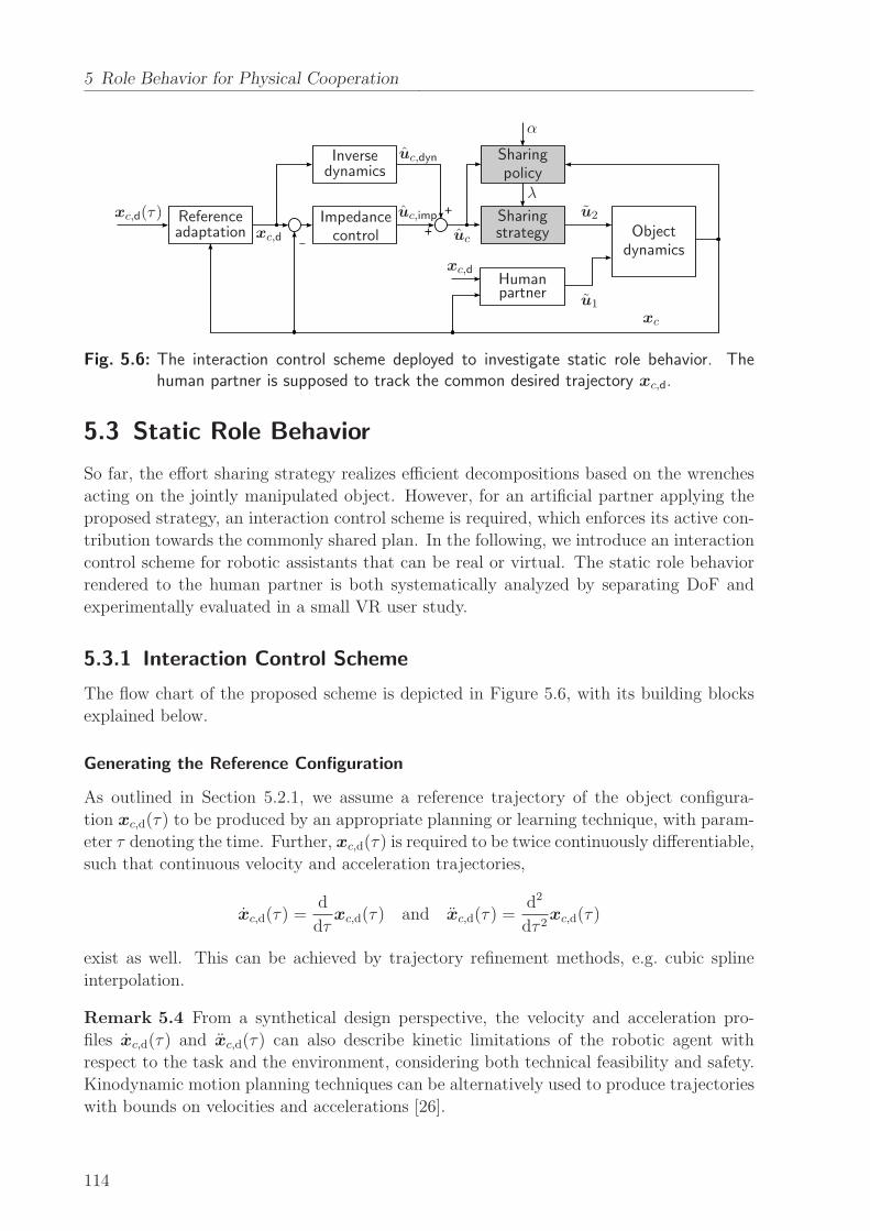
5 Role Behavior for Physical Cooperation
_
+
+xc,d
xc,d
xc,d(τ)
α
Referenceadaptation
Inversedynamics
Sharingpolicy
Sharingstrategy
λ
Objectdynamics
Impedancecontrol
Humanpartner
u1
xc
uc
u2
uc,dyn
uc,imp
Fig. 5.6: The interaction control scheme deployed to investigate static role behavior. Thehuman partner is supposed to track the common desired trajectory xc,d.
5.3 Static Role Behavior
So far, the effort sharing strategy realizes efficient decompositions based on the wrenches
acting on the jointly manipulated object. However, for an artificial partner applying the
proposed strategy, an interaction control scheme is required, which enforces its active con-
tribution towards the commonly shared plan. In the following, we introduce an interaction
control scheme for robotic assistants that can be real or virtual. The static role behavior
rendered to the human partner is both systematically analyzed by separating DoF and
experimentally evaluated in a small VR user study.
5.3.1 Interaction Control Scheme
The flow chart of the proposed scheme is depicted in Figure 5.6, with its building blocks
explained below.
Generating the Reference Configuration
As outlined in Section 5.2.1, we assume a reference trajectory of the object configura-
tion xc,d(τ) to be produced by an appropriate planning or learning technique, with param-
eter τ denoting the time. Further, xc,d(τ) is required to be twice continuously differentiable,
such that continuous velocity and acceleration trajectories,
xc,d(τ) =d
dτxc,d(τ) and xc,d(τ) =
d2
dτ 2xc,d(τ)
exist as well. This can be achieved by trajectory refinement methods, e.g. cubic spline
interpolation.
Remark 5.4 From a synthetical design perspective, the velocity and acceleration pro-
files xc,d(τ) and xc,d(τ) can also describe kinetic limitations of the robotic agent with
respect to the task and the environment, considering both technical feasibility and safety.
Kinodynamic motion planning techniques can be alternatively used to produce trajectories
with bounds on velocities and accelerations [26].
114
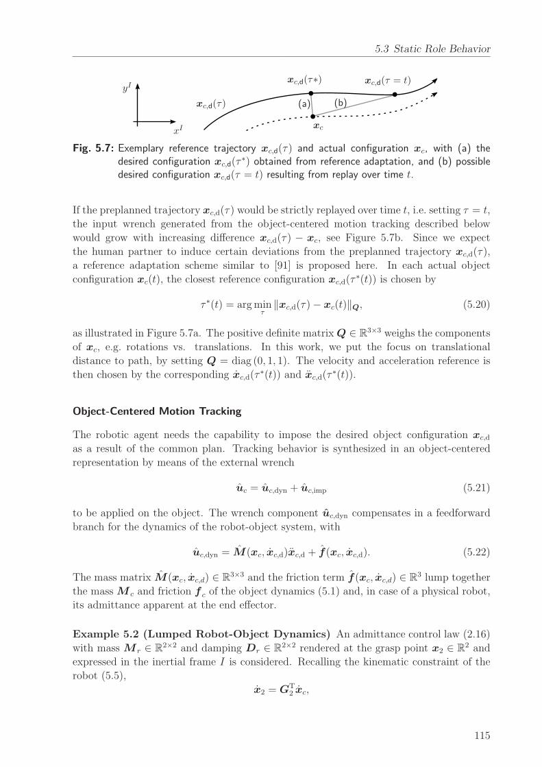
5.3 Static Role Behavior
xc,d(τ)
xc,d(τ∗) xc,d(τ = t)
xc
(a) (b)
xI
yI
Fig. 5.7: Exemplary reference trajectory xc,d(τ) and actual configuration xc, with (a) thedesired configuration xc,d(τ
∗) obtained from reference adaptation, and (b) possibledesired configuration xc,d(τ = t) resulting from replay over time t.
If the preplanned trajectory xc,d(τ) would be strictly replayed over time t, i.e. setting τ = t,
the input wrench generated from the object-centered motion tracking described below
would grow with increasing difference xc,d(τ) − xc, see Figure 5.7b. Since we expect
the human partner to induce certain deviations from the preplanned trajectory xc,d(τ),
a reference adaptation scheme similar to [91] is proposed here. In each actual object
configuration xc(t), the closest reference configuration xc,d(τ∗(t)) is chosen by
τ ∗(t) = argminτ
‖xc,d(τ)− xc(t)‖Q, (5.20)
as illustrated in Figure 5.7a. The positive definite matrixQ ∈ R3×3 weighs the components
of xc, e.g. rotations vs. translations. In this work, we put the focus on translational
distance to path, by setting Q = diag (0, 1, 1). The velocity and acceleration reference is
then chosen by the corresponding xc,d(τ∗(t)) and xc,d(τ
∗(t)).
Object-Centered Motion Tracking
The robotic agent needs the capability to impose the desired object configuration xc,d
as a result of the common plan. Tracking behavior is synthesized in an object-centered
representation by means of the external wrench
uc = uc,dyn + uc,imp (5.21)
to be applied on the object. The wrench component uc,dyn compensates in a feedforward
branch for the dynamics of the robot-object system, with
uc,dyn = M(xc, xc,d)xc,d + f(xc, xc,d). (5.22)
The mass matrix M(xc, xc,d) ∈ R3×3 and the friction term f(xc, xc,d) ∈ R
3 lump together
the mass M c and friction f c of the object dynamics (5.1) and, in case of a physical robot,
its admittance apparent at the end effector.
Example 5.2 (Lumped Robot-Object Dynamics) An admittance control law (2.16)
with mass M r ∈ R2×2 and damping Dr ∈ R
2×2 rendered at the grasp point x2 ∈ R2 and
expressed in the inertial frame I is considered. Recalling the kinematic constraint of the
robot (5.5),
x2 = GT2 xc,
115

5 Role Behavior for Physical Cooperation
we obtain through derivation
x2 = GT2 xc + G
T
2 xc. (5.23)
Using (5.3) and (5.23), the inertial wrench component of (5.22) is then superposed by
M(xc, xc,d)xc,d = M cxc,d +G2M r
(
GT2 xc,d + G
T
2 xc,d
)
.
Similarly, via (5.3) and (5.5) the friction term of (5.22) is calculated by
f (xc, xc,d) = f c(xc, xc,d) +G2DrGT2 xc,d.
Remark 5.5 Apart from the feedback configuration xc, the inverse dynamics (5.22) rely
on feedforward variables (xc,d, xc,d). Using their corresponding feedback variables would
result in total cancellation of the robot-object dynamics, which is obviously unrealizable.
An object-centered impedance-type control law acting on the tracking error of the con-
figuration xc generates the feedback component of the external wrench
uc,imp = Kp(xc,d − xc) +Kd(xc,d − xc). (5.24)
The stiffness gain Kp ∈ R3×3 and the damping gain Kd ∈ R3×3 render a compliant
behavior guaranteeing smooth rising of counteracting wrenches, if the object configuration
deviates from the expected.
Embedding the Effort Sharing Strategy
The external wrench (5.21) guaranteeing object-centered motion tracking feeds the effort
sharing strategy. The applied wrench of the robot u2 is calculated as the solution (5.10)
to the effort sharing problem, based on the configuration-dependent parameter λ. Us-
ing (5.17), the static role is then defined by the effort sharing policy (5.19), i.e. the volun-
tary contribution of the robot for a certain choice of the policy parameter α. Note, that the
scheme from Figure 5.6 assumes a robotic agent capable to ideally apply the wrench u2.
For physical agents, the dynamics of force control need to be considered as well, which will
be addressed later.
Remark 5.6 The effort sharing strategy can be regarded as a selective filter acting on the
external wrench uc, depending on the imposed role.
Remark 5.7 The role of the human is assumed complementary and allocated in a feed-
forward, centralized manner. Hence, the actual applied wrench of the human u1 does not
necessarily agree. We will experimentally investigate the effects of static role behavior on
cooperative pHRI.
5.3.2 Analysis of the Interactive Behavior
A better understanding of the overall interactive behavior rendered by the previously
introduced interaction control scheme is sought through an analysis of the robot-object
116
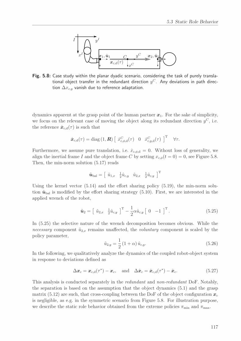
5.3 Static Role Behavior
xI
yII
xC
yCCx1, u1 x2, u2
xc,d(τ)
Fig. 5.8: Case study within the planar dyadic scenario, considering the task of purely transla-tional object transfer in the redundant direction yC . Any deviations in path direc-tion ∆xc,y vanish due to reference adaptation.
dynamics apparent at the grasp point of the human partner x1. For the sake of simplicity,
we focus on the relevant case of moving the object along its redundant direction yC , i.e.
the reference xc,d(τ) is such that
xc,d(τ) = diag (1,R)[
xCc,φ,d(τ) 0 xCc,y,d(τ)]T ∀τ.
Furthermore, we assume pure translation, i.e. xc,φ,d = 0. Without loss of generality, we
align the inertial frame I and the object frame C by setting xc,φ(t = 0) = 0, see Figure 5.8.
Then, the min-norm solution (5.17) reads
ubal =[
u1,x12uc,y u2,x
12uc,y
]T
Using the kernel vector (5.14) and the effort sharing policy (5.19), the min-norm solu-
tion ubal is modified by the effort sharing strategy (5.10). First, we are interested in the
applied wrench of the robot,
u2 =[
u2,x12uc,y
]T − 1
2αuc,y
[
0 −1]T. (5.25)
In (5.25) the selective nature of the wrench decomposition becomes obvious. While the
necessary component u2,x remains unaffected, the voluntary component is scaled by the
policy parameter,
u2,y =1
2(1 + α) uc,y. (5.26)
In the following, we qualitatively analyze the dynamics of the coupled robot-object system
in response to deviations defined as
∆xc = xc,d(τ∗)− xc, and ∆xc = xc,d(τ
∗)− xc. (5.27)
This analysis is conducted separately in the redundant and non-redundant DoF. Notably,
the separation is based on the assumption that the object dynamics (5.1) and the grasp
matrix (5.12) are such, that cross-coupling between the DoF of the object configuration xc
is negligible, as e.g. in the symmetric scenario from Figure 5.8. For illustration purpose,
we describe the static role behavior obtained from the extreme policies πmin and πmax.
117
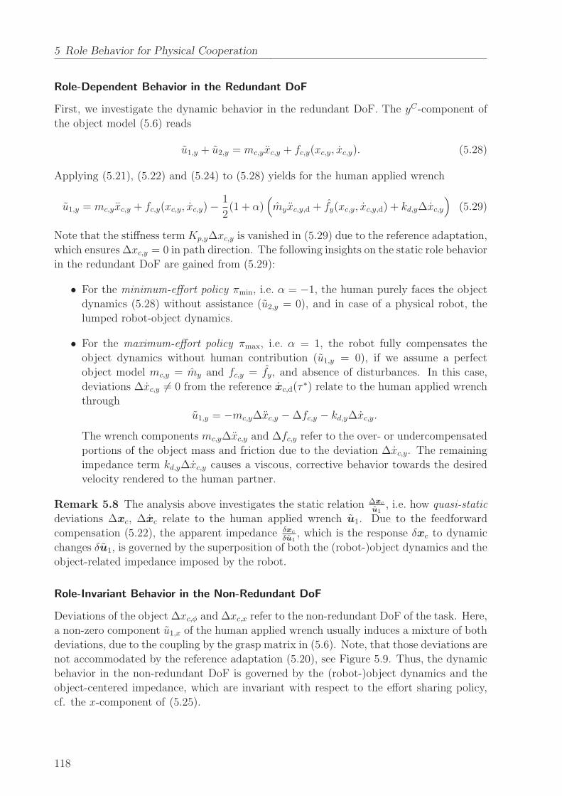
5 Role Behavior for Physical Cooperation
Role-Dependent Behavior in the Redundant DoF
First, we investigate the dynamic behavior in the redundant DoF. The yC-component of
the object model (5.6) reads
u1,y + u2,y = mc,yxc,y + fc,y(xc,y, xc,y). (5.28)
Applying (5.21), (5.22) and (5.24) to (5.28) yields for the human applied wrench
u1,y = mc,yxc,y + fc,y(xc,y, xc,y)−1
2(1 + α)
(
myxc,y,d + fy(xc,y, xc,y,d) + kd,y∆xc,y
)
(5.29)
Note that the stiffness term Kp,y∆xc,y is vanished in (5.29) due to the reference adaptation,
which ensures ∆xc,y = 0 in path direction. The following insights on the static role behavior
in the redundant DoF are gained from (5.29):
• For the minimum-effort policy πmin, i.e. α = −1, the human purely faces the object
dynamics (5.28) without assistance (u2,y = 0), and in case of a physical robot, the
lumped robot-object dynamics.
• For the maximum-effort policy πmax, i.e. α = 1, the robot fully compensates the
object dynamics without human contribution (u1,y = 0), if we assume a perfect
object model mc,y = my and fc,y = fy, and absence of disturbances. In this case,
deviations ∆xc,y 6= 0 from the reference xc,d(τ∗) relate to the human applied wrench
through
u1,y = −mc,y∆xc,y −∆fc,y − kd,y∆xc,y.
The wrench components mc,y∆xc,y and ∆fc,y refer to the over- or undercompensated
portions of the object mass and friction due to the deviation ∆xc,y. The remaining
impedance term kd,y∆xc,y causes a viscous, corrective behavior towards the desired
velocity rendered to the human partner.
Remark 5.8 The analysis above investigates the static relation ∆xc
u1, i.e. how quasi-static
deviations ∆xc, ∆xc relate to the human applied wrench u1. Due to the feedforward
compensation (5.22), the apparent impedance δxc
δu1, which is the response δxc to dynamic
changes δu1, is governed by the superposition of both the (robot-)object dynamics and the
object-related impedance imposed by the robot.
Role-Invariant Behavior in the Non-Redundant DoF
Deviations of the object ∆xc,φ and ∆xc,x refer to the non-redundant DoF of the task. Here,
a non-zero component u1,x of the human applied wrench usually induces a mixture of both
deviations, due to the coupling by the grasp matrix in (5.6). Note, that those deviations are
not accommodated by the reference adaptation (5.20), see Figure 5.9. Thus, the dynamic
behavior in the non-redundant DoF is governed by the (robot-)object dynamics and the
object-centered impedance, which are invariant with respect to the effort sharing policy,
cf. the x-component of (5.25).
118
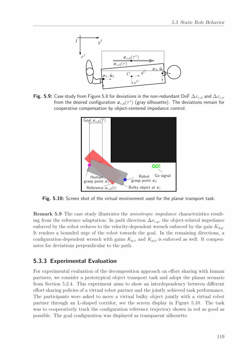
5.3 Static Role Behavior
xI
yII
xC
yCCx1, u1
x2, u2
xc,d(τ)
xc,d(τ∗)
Fig. 5.9: Case study from Figure 5.8 for deviations in the non-redundant DoF ∆xc,φ and ∆xc,xfrom the desired configuration xc,d(τ
∗) (gray silhouette). The deviations remain forcooperative compensation by object-centered impedance control.
Goal xc,d(T )
Robotgrasp point x2
Humangrasp point x1
Bulky object at xcReference xc,d(t)
Go signal
Fig. 5.10: Screen shot of the virtual environment used for the planar transport task.
Remark 5.9 The case study illustrates the anisotropic impedance characteristics result-
ing from the reference adaptation: In path direction ∆xc,y, the object-related impedance
enforced by the robot reduces to the velocity-dependent wrench enforced by the gain Kd,y.
It renders a bounded urge of the robot towards the goal. In the remaining directions, a
configuration-dependent wrench with gains Kp,x and Kp,φ is enforced as well. It compen-
sates for deviations perpendicular to the path.
5.3.3 Experimental Evaluation
For experimental evaluation of the decomposition approach on effort sharing with human
partners, we consider a prototypical object transport task and adopt the planar scenario
from Section 5.2.4. This experiment aims to show an interdependency between different
effort sharing policies of a virtual robot partner and the jointly achieved task performance.
The participants were asked to move a virtual bulky object jointly with a virtual robot
partner through an L-shaped corridor, see the screen display in Figure 5.10. The task
was to cooperatively track the configuration reference trajectory shown in red as good as
possible. The goal configuration was displayed as transparent silhouette.
119
5 Role Behavior for Physical Cooperation
Remark 5.10 In the virtual scenario, the term bulky refers to the relative dimensions of
the object with respect to the environment, rather than its absolute expansion.
Conditions
Three conditions manipulated the effort sharing policy of the virtual robotic partner:
• MIN: Minimum robot effort.
Applying the policy parameter α = −1, the robot only contributes to the steering
motion but leaves the entire effort in the sharing direction (yC) to the human.
• BAL: Balanced effort.
The balanced-effort strategy achieved by α = 0 results in a robot behavior contribut-
ing to steering as well as half of the required effort in the sharing direction.
• MAX: Maximum robot effort.
By setting α = 1, the robot fulfills the tracking motion in the direction of sharing
completely alone. The human force input is only required for steering.
Participants, Setup and Procedure
Ten unpaid, male participants took part in this experiment. They were between 24 and 33
years old, at a mean age of 27.7 years. All were right handed and had normal or corrected-
to-normal vision.
Through the VR-System described in Appendix A.1, the participants were able to
apply forces to the object at the given human grasp point on the opposite side of
the grasp point of the virtual partner. Visual-haptic rendering of the virtual environ-
ment was performed as explained in Appendix B. The virtual object was assigned the
mass M c = diag(
0.042 kgm2, 20 kg, 20 kg)
, and the dimensions of 0.15m by 0.05m. Its
motion was damped by isotropic, viscous friction Dc = 120Nsm−1 · I4, acting at the
grasp points x1,2. The virtual robot applied the interaction control scheme from Sec-
tion 5.3.1 to shape its force input to the object. Since we aim to isolate the effects
of the effort role behavior, a pre-planned, fixed configuration trajectory was assumed.
The reference trajectory xc,d(τ), with xc,d(τ), xc,d(τ) was generated from supporting
points and then interpolated using cubic splines. The desired configuration xc,d was cho-
sen by the reference adaptation, depending on the current configuration. The object-
centered impedance was set to Kp = diag(
1.0Nmrad−1, 100.0Nm−1, 100.0Nm−1)
and
to Kd =(
0.6Nmsrad−1, 50.0Nsm−1, 50.0Nsm−1)
, respectively.
For each of the three conditions, a sequence of five trials was performed. The sequences
were randomized for each participant. Participants were informed about the behavior they
could expect from the virtual partner before each sequence. Each trial took T = 13 s,
regardless of the final object configuration. A five-second break allowed the participants
to settle between each trial. The first trial of each sequence was discarded from further
evaluation.
120
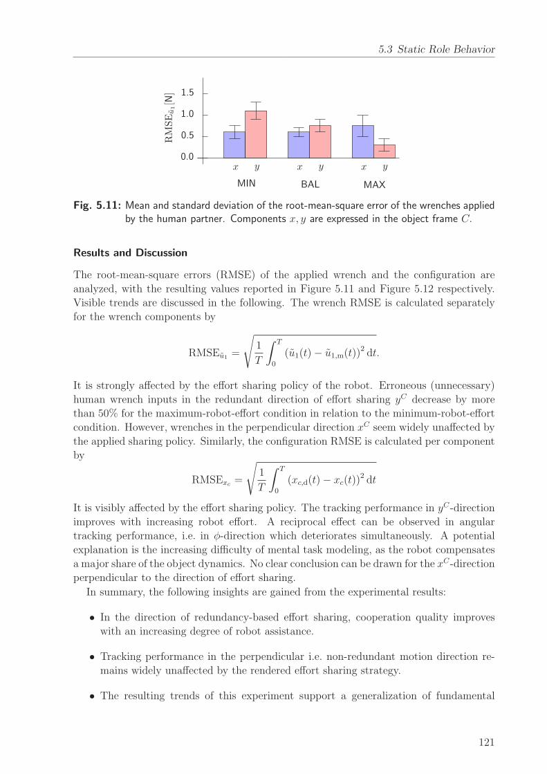
5.3 Static Role Behavior
0.0
0.5
1.0
1.5
RMSEu1[N]
xxx yyy
MIN BAL MAX
Fig. 5.11: Mean and standard deviation of the root-mean-square error of the wrenches appliedby the human partner. Components x, y are expressed in the object frame C.
Results and Discussion
The root-mean-square errors (RMSE) of the applied wrench and the configuration are
analyzed, with the resulting values reported in Figure 5.11 and Figure 5.12 respectively.
Visible trends are discussed in the following. The wrench RMSE is calculated separately
for the wrench components by
RMSEu1 =
√
1
T
∫ T
0
(u1(t)− u1,m(t))2 dt.
It is strongly affected by the effort sharing policy of the robot. Erroneous (unnecessary)
human wrench inputs in the redundant direction of effort sharing yC decrease by more
than 50% for the maximum-robot-effort condition in relation to the minimum-robot-effort
condition. However, wrenches in the perpendicular direction xC seem widely unaffected by
the applied sharing policy. Similarly, the configuration RMSE is calculated per component
by
RMSExc=
√
1
T
∫ T
0
(xc,d(t)− xc(t))2 dt
It is visibly affected by the effort sharing policy. The tracking performance in yC-direction
improves with increasing robot effort. A reciprocal effect can be observed in angular
tracking performance, i.e. in φ-direction which deteriorates simultaneously. A potential
explanation is the increasing difficulty of mental task modeling, as the robot compensates
a major share of the object dynamics. No clear conclusion can be drawn for the xC-direction
perpendicular to the direction of effort sharing.
In summary, the following insights are gained from the experimental results:
• In the direction of redundancy-based effort sharing, cooperation quality improves
with an increasing degree of robot assistance.
• Tracking performance in the perpendicular i.e. non-redundant motion direction re-
mains widely unaffected by the rendered effort sharing strategy.
• The resulting trends of this experiment support a generalization of fundamental
121
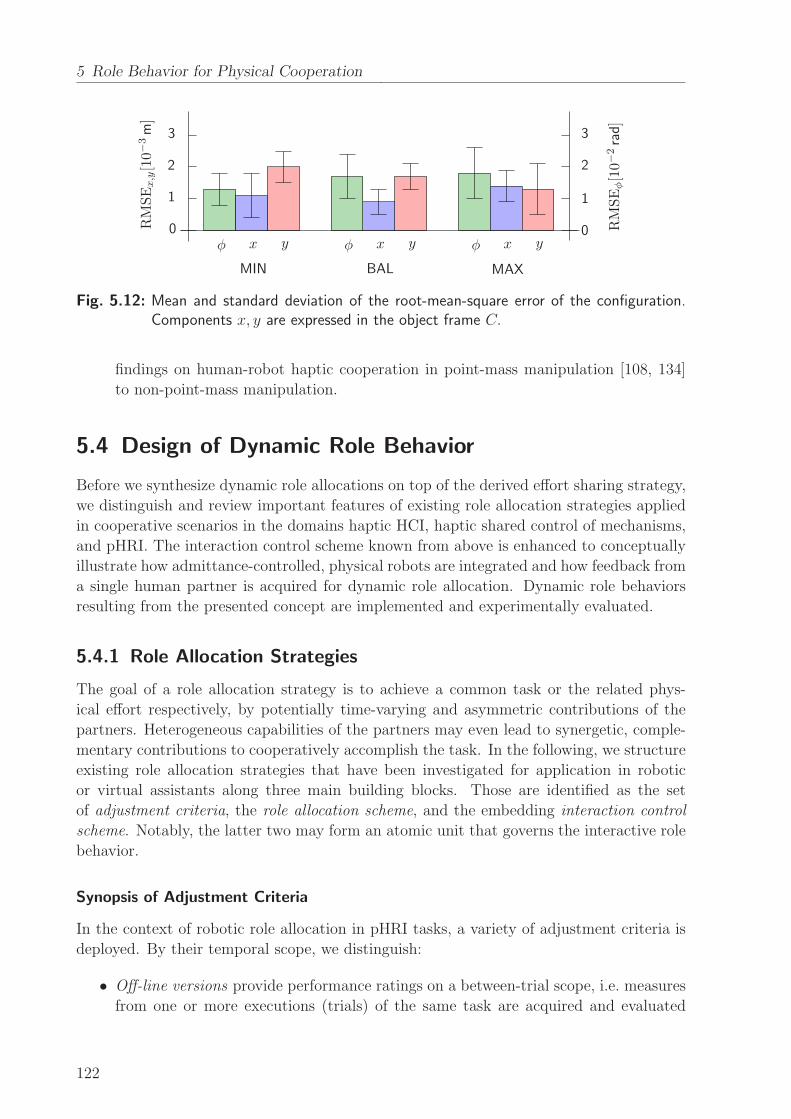
5 Role Behavior for Physical Cooperation
0
1
2
3
0
1
2
3RMSEx,y[10−3m]
RMSEφ[10−2rad]
φφφ xxx yyy
MIN BAL MAX
Fig. 5.12: Mean and standard deviation of the root-mean-square error of the configuration.Components x, y are expressed in the object frame C.
findings on human-robot haptic cooperation in point-mass manipulation [108, 134]
to non-point-mass manipulation.
5.4 Design of Dynamic Role Behavior
Before we synthesize dynamic role allocations on top of the derived effort sharing strategy,
we distinguish and review important features of existing role allocation strategies applied
in cooperative scenarios in the domains haptic HCI, haptic shared control of mechanisms,
and pHRI. The interaction control scheme known from above is enhanced to conceptually
illustrate how admittance-controlled, physical robots are integrated and how feedback from
a single human partner is acquired for dynamic role allocation. Dynamic role behaviors
resulting from the presented concept are implemented and experimentally evaluated.
5.4.1 Role Allocation Strategies
The goal of a role allocation strategy is to achieve a common task or the related phys-
ical effort respectively, by potentially time-varying and asymmetric contributions of the
partners. Heterogeneous capabilities of the partners may even lead to synergetic, comple-
mentary contributions to cooperatively accomplish the task. In the following, we structure
existing role allocation strategies that have been investigated for application in robotic
or virtual assistants along three main building blocks. Those are identified as the set
of adjustment criteria, the role allocation scheme, and the embedding interaction control
scheme. Notably, the latter two may form an atomic unit that governs the interactive role
behavior.
Synopsis of Adjustment Criteria
In the context of robotic role allocation in pHRI tasks, a variety of adjustment criteria is
deployed. By their temporal scope, we distinguish:
• Off-line versions provide performance ratings on a between-trial scope, i.e. measures
from one or more executions (trials) of the same task are acquired and evaluated
122
5.4 Design of Dynamic Role Behavior
afterwards. In general, those criteria are suited equally well for evaluation and com-
parison of robotic implementations in pHRI experiments.
• On-line versions yield performance ratings on a within-trial scope, taken from in-
stantaneous measurements. Averaging over finite time windows or integrating instan-
taneous measurements over the course of the trial, possibly with forgetting factors,
comprises multiple measurement samples in the criterion.
Implemented adjustment criteria found in literature focus on sensory information extracted
through the haptic modality, as it is considered fundamental to the role allocation problem
and intuitively accessible through the physical coupling. In the context of goal-directed
pHRI tasks, spatio-temporal criteria are applied frequently, such as:
• Completion time of the task. The velocity of the object measuring the task progress
towards the goal may be taken as the differential, on-line version [123].
• Spatial deviations from a reference path or trajectory of the common object or in-
teraction point [191]. Those are applicable only in pursuit tracking tasks, where a
preferred or optimal common reference can be defined.
• Spatial distance to obstacles to be avoided in the environment [144, 191] as well
as distance to self-collision as an exemplary individual constraint of the robotic
agent [32]. If admissible for the task, also the number of collisions with obstacles or
the time being in contact with forbidden regions is used [123].
• Movement variability of the partner as the predicted covariance [104] or the obser-
vation likelihood [169] of the motion state drawn from a probabilistic model of the
partner’s task-related behavior. The task model is built by several—initially un-
der passive assistance, to allow for observation—cooperative executions of the same
task [90, 199].
The close coupling in pHRI gives rise to criteria that assess the physical effort spent by
the partners:
• Norm of the applied wrench of the partner, averaged over execution time [122]. Any
kind of interaction force at the grasp point is interpreted as effort, no matter of its
direction, or whether it is actively induced through muscular contraction or purely
resulting from passive limb dynamics.
Negotiation processes between the partners due to individual deviations from the common
plan and disagreement due to differing intentions are assessed by:
• Norm of the internal wrench on the object or interaction point, averaged over exe-
cution time [122]. Internal wrenches, no matter of the sign, are waisted effort with
respect to task efficiency, since they do not cause motion but only internal stress.
Yet, the internal wrenches, which are also called interactive forces [48], are purposeful
for the communication between the partners through haptics.
123

5 Role Behavior for Physical Cooperation
• Deviations from a reference wrench [113]. Going below or beyond certain thresholds
on previously acquired wrench profiles is interpreted as the partner’s intent to shift
the control authority.
• Expected variabilities of the partner’s contribution, given by the predicted variance
of the partner’s wrench input. The latter is obtained from a probabilistic task
model [104]. The current variabilities given by the windowed sample covariance of
the measured wrench input are employed to additionally represent an instantaneous
level of disagreement [105].
Some works investigate the interaction and merging of multiple adjustment criteria for
the purpose of role allocation. Weighted superpositions of multiple measures into a single,
scalar-valued performance index are applied in [122, 123, 191]. In the modified, linear-
quadratic control approach of [104, 105], weighing of input and movement variabilities is
defined by the parameters of the cost functional.
Remark 5.11 Weighing of multiple criteria usually implies a trade-off and remains sub-
ject to design, as their individual importance may depend on the characteristics of the
task, the environmental situation and also the partner. Normalized formulations of the
criteria may facilitate a more intuitive design of the weighing.
Role Allocation Schemes with Explicit Policy Parameters
Similar to the effort sharing policies derived above, roles are frequently characterized by
means of a bounded scalar variable, which we commonly denote by the policy parameter α
in the following. Note, that in literature, the terms blending variable, assistance level
or policy parameter are often used synonymously. Such parameterization allows to treat
role allocation and interaction control as divisible problems. The actual role or assistance
behavior of the artificial agent is then subject to interaction control, which renders the
task-dependent wrench contribution.
Some of the aforementioned adjustment criteria may be instantaneously and explicitly
mapped to corresponding values of the policy parameter, usually after normalization [169].
Smooth trigonometric blending to model the functional dependency on single criteria and
non-linear adaptation laws depending on a multi-criterion performance index are found
in [32, 191]. Role blending based on a finite state machine with state transitions triggered
by threshold conditions on the adjustment criterion is proposed by [113], and hysteresis-
based blending is applied in [123].
Constant assistance levels may be derived, which are optimal with respect to some
single or multi-criterion performance index. Evaluations of the performance index for one
or several executions of the cooperative task under systematic variation of the assistance
level allow to model static functional relationships between the former and the latter, e.g.
through polynomial fitting [122].
Passenberg et al. [123] also propose continuously changing assistance levels as a result of
linear adjustment laws, for which performance error measures are defined and minimized.
This kind of role allocation can be understood as a tracking control problem of an on-line
performance index with respect to a certain reference performance.
124
5.4 Design of Dynamic Role Behavior
Remark 5.12 The policy parameter is usually embedded in the control scheme as pro-
portional scaling factor, that directly modulates the control input. Therefore, blending
techniques such as low-pass filtering are applied frequently to obtain a continuous-valued
policy parameter and smooth control inputs [113, 123]. Suitable choices for blending times
lie above or in the order of human motor response times [86], to give human partners the
opportunity to successfully accommodate to the changing role behavior.
Embedding Schemes for Interaction Control and Assistance
All of the schemes reviewed below assume the grasp points of the cooperating dyad to be
coincident with the object configuration. Therefore, the cooperative manipulation problem
reduces to a single interaction point x1 = x2 = xc. Furthermore, all of both agents’
input components provide full actuation redundancy, i.e. the independent control inputs
fulfill n1 = n2 = nc. A popular example task applied in such setting is the cooperative
manipulation of point-mass objects. For the sake of clarity, we continue the notation used
in this chapter.
The controller blending scheme proposed by Evrard and Kheddar [31] renders variable
role behavior that allows role allocation by an independent blending variable αi ∈ [0, 1]
per agent i = 1, 2. The mathematical notion of homotopy between a pair of functions is
exploited to render a blend of control inputs
ui = αiL+ (1− αi)F , (5.30)
with L and F being template controllers for the extreme cases of a leader and a follower re-
spectively. The leader and follower are implemented for instance by two distinct impedance
controllers similar to (5.24), e.g. a low or zero-stiffness follower controller with vanishing
wrench input and a stiff leader controller enforcing the desired object motion. The grad-
ual blend of two extreme controllers for each agent may render a variety of interaction
behaviors.
Though being rather tailored to computer-assisted tele-operation than cooperative pHRI
scenarios, variable assistance levels provided by guiding virtual fixtures are equivalent the
role allocation problem of a virtual partner. In [122, 123] for example, guidance behavior
towards a predefined, error-free path xc,d(τ) is rendered by the composition of a passive
virtual fixture in path direction, and by an active virtual fixture perpendicular to the
path direction. With the deviation ∆xc and ∆xc from (5.27) generated by a reference
adaptation scheme (5.20), the applied wrench of such an assistance reads
u2 = α‖ cf (sgn (∆xc)) u1,m‖ + α⊥Kp,⊥∆xc. (5.31)
The passive virtual fixture is obtained from up or down scaling of the measured applied
wrench of the human u1,m‖ in path direction by the function cf : R → R, depending
on the direction of motion sgn (∆xc). Spring-like compensation of deviations ∆xc with
stiffness Kp,⊥ ∈ Rnc×nc is provided by the active virtual fixture perpendicular to the
path. The role allocation problem in multiple redundant DoF is decomposed into a single
DoF in path direction, which is governed by the assistance level α‖ and the remaining,
125
5 Role Behavior for Physical Cooperation
perpendicular DoF, which are governed by α⊥, with both α‖, α⊥ ∈ [0, 1].
Remark 5.13 The role allocations, each generating a time-varying assistance level or
policy parameter, may be designed based on different adjustment criteria and separately
in DoF. Yet, strict decompositions neglect potentially remaining interdependencies of the
adjustment criteria between DoF.
Remark 5.14 The passive virtual fixture in (5.31) renders the role behavior of a sup-
portive follower. Variable parts of the human applied wrench u1,m‖ are replicated by the
assistance, resulting in an effort contribution mirrored to that of the human. Such an as-
sistance scheme does not feature a proactive, autonomous urge towards the common goal.
The active virtual fixture in (5.31) acting in perpendicular DoF renders a compensating
behavior equivalent to the one analyzed in Section 5.3.2.
Implicit Role Allocation by Optimal Feedback Control
In a control-theoretic approach, both the role distribution (even the role allocation) and in-
teraction control are an inextricable and implicit result of control design, i.e. the approach
does not rely on an explicit policy parameter. Rigorous, cost-based formulation of inter-
active behaviors and role distributions is proposed by Jarrasse et al. [69]. Through cost
function templates considering task error and effort terms of both contributors, the authors
are able to simulate a variety of dyadic interactive behaviors by different parameterizations
of linear-quadratic controllers. Dynamic role allocation by optimal control techniques is
investigated in [104, 105, 144]. A linear state feedback control law renders the control
input to the linear task dynamics, which is the input wrench of a virtual assistant,
u2 = −K(
ξc − ξc,d)
. (5.32)
By defining the state ξc = [ xc xc ]T composed by the position and velocity of the
grasp point of the assistant, (5.32) resembles an impedance-type tracking of the desired
state ξc,d ∈ R2nc with feedback matrix K(t) ∈ Rnc×2nc . Variable stiffness and damping
gains result from choosing K(t) as the solution of the risk-sensitive optimal feedback
control problem, where the assistance policy is represented by a cost function depending
on the process noise.
Remark 5.15 Depending on the parameterization of the cost function, the gain values
in K(t) dynamically rise or fall as a function of the variabilities of both the human input
and movements, resembling e.g. a risk-seeking or risk-averse role allocation behavior (atti-
tude) of the assistant. The systematic, cost-minimizing formulation renders this approach
theoretically appealing.
In the following, we synthesize both a continuous and a discrete role allocation scheme
based on explicit, dynamical formulations of the policy parameter α(t). Specifically, the
instantaneous agreement of the human partner, defined by interactive forces, is employed
as an on-line adjustment criterion for role allocation.
126
5.4 Design of Dynamic Role Behavior
5.4.2 Synthesis of Role Allocations
The effort sharing policies (5.19) derived in Section 5.2.4 with constant policy parameter α
imply a static role behavior in terms of the effort sharing ratio among the dyad in the
redundant direction. They furthermore result from a feedforward calculation of the agents’
applied wrenches, which can not be imposed to human partners. In contrast, the dynamic
role allocation strategies developed in the following vary the policy parameter α over time
during task execution. Here, wrench feedback from the human partner is considered in a
single adjustment criterion.
Remark 5.16 The role and the corresponding allocation strategy refers to a single redun-
dant DoF of the task. As outlined above, the partners may apply different role allocation
schemes in each of multiple redundant DoF.
Remark 5.17 The resulting robot behavior in terms of its autonomous urge towards the
task goal is influenced by the velocity profile xc(τ) of the configuration trajectory planned
by the robot.
Constant Role Allocation as Baseline
The baseline strategy with respect to the experimental evaluation that will follow in Sec-
tion 5.5, is defined by a role allocation remaining constant over the course of the task.
Any arbitrary choice of a constant parameter α directly affects the urge of the robot to
accomplish the task. Given a certain reference velocity profile, the choice of α = 0 results
in an equal, feedforward composition of the external wrench in the redundant DoF. This
case is particularly appealing due to its symmetry: A human partner applying the same
wrench as the robot in the redundant DoF moves the object according to the reference
velocity profile of the robot. In contrast, a human partner who applies the same wrench
in the opposite direction cancels the applied wrench of the robot.
Remark 5.18 Similar to the choice of the velocity profile xc(τ), the value of the policy
parameter α defining a constant role allocation may be chosen depending on performance
evaluations from previous task executions.
Weighted Proactive Role Allocation
Dynamic role behavior is realized by a weighted proactive role allocation strategy. We
propose a continuous, first order integrator that governs the policy parameter according
to
α(t) = α0 +
∫ t
t0
α(τ)dτ, (5.33)
with the initial policy value α0. Boundedness, i.e. α ∈ [−1, 1], is ensured by an anti-
windup saturation to allocate only efficient policies. The rate of change of the policy α(t)
127
5 Role Behavior for Physical Cooperation
is designed to switch between the cases
α(t) =
−τw−
∣
∣uC1,y(t)∣
∣ , if ξ(t) = 0
τw+ uCy,th, if ξ(t) = 1 ∧
∣
∣uC1,y(t)∣
∣ < uCy,th
τw+
∣
∣uC1,y(t)∣
∣ , otherwise.
(5.34)
The meaning of the feedback variables and parameters in (5.34) and their effects are
explained as follows:
• Different alternatives to construct an indicator of human agreement exist, as dis-
cussed in the previous section. In this work, we define agreement straightforwardly
by means of human wrench feedback. The binary variable ξ(t) ∈ {0, 1} represents
the human instantaneous (dis-)agreement. With the component uC1,y(t) denoting the
estimate of the wrench currently applied by the human in the redundant direction,
we define the agreement variable
ξ(t) =
{
0, if sgn(
uC1,y(t))
6= sgn(
uC1,y(t))
∧∣
∣uC1,y(t)∣
∣ > uCy,agr
1, otherwise.(5.35)
Thus, (dis-)agreement is determined by comparing the directions of the wrench uC1,y(t)
resulting from feedforward calculation and the actually applied wrench uC1,y(t).
• The positive threshold uCy,agr ∈ R+ captures human wrench inputs close to zero.
Those are treated as neutral or silent agreement, i.e. the contribution of the robot
rises proactively and gradually. This behavior is designed under the assumption, that
the partner would clearly indicate his/her disagreement through non-zero wrenches.
Setting the initial value α0 = −1 in (5.33) produces initially a minimum-robot-effort
behavior.
• The positive constants τw− ∈ R+ and τw+ ∈ R
+ define the fundamental decay and
rise times of the policy parameter α. When designing assistive behavior, a faster
reaction to disagreement (ξ = 0) than to agreement (ξ = 1) is considered to be a
reasonable option, i.e. τw− > τw+ > 0. This choice lets the role behavior rapidly fall
back to minimum effort, if the human signals discomfort by applying a counteracting
wrench.
• The factor∣
∣uC1,y(t)∣
∣ performs a dynamic weighing, which yields a role behavior with
a progressively changing policy depending on the magnitude of the partner’s con-
tribution. High wrench magnitudes are interpreted to emphasize (dis-)agreement,
and thus, speed up the role allocation dynamics accordingly. The positive thresh-
old uCy,th ∈ R+ defines a lower bound on the weighing factor, that still lets the robot
contribution rise in case of small partner wrenches.
The qualitative behavior of the weighted proactive role allocation with α0 = −1 is illus-
trated by means of a simulation example depicted in Figure 5.13a.
128
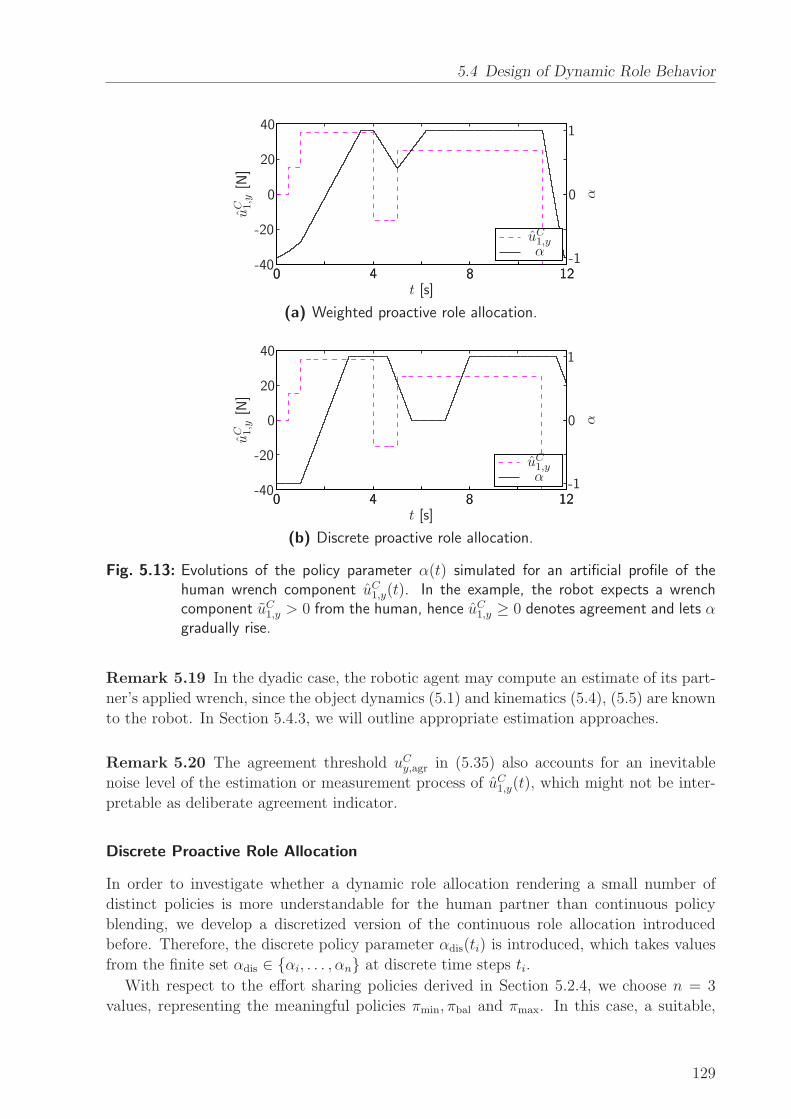
5.4 Design of Dynamic Role Behavior
αuC1,y
uC 1,y
[N]
t [s]
α0
0
0
0 44 88 1212
-20
-40
20
40
-1
1
(a) Weighted proactive role allocation.
αuC1,y
uC 1,y
[N]
t [s]
α0
0
0
0 44 88 1212
-20
-40
20
40
-1
1
(b) Discrete proactive role allocation.
Fig. 5.13: Evolutions of the policy parameter α(t) simulated for an artificial profile of thehuman wrench component uC1,y(t). In the example, the robot expects a wrenchcomponent uC1,y > 0 from the human, hence uC1,y ≥ 0 denotes agreement and lets αgradually rise.
Remark 5.19 In the dyadic case, the robotic agent may compute an estimate of its part-
ner’s applied wrench, since the object dynamics (5.1) and kinematics (5.4), (5.5) are known
to the robot. In Section 5.4.3, we will outline appropriate estimation approaches.
Remark 5.20 The agreement threshold uCy,agr in (5.35) also accounts for an inevitable
noise level of the estimation or measurement process of uC1,y(t), which might not be inter-
pretable as deliberate agreement indicator.
Discrete Proactive Role Allocation
In order to investigate whether a dynamic role allocation rendering a small number of
distinct policies is more understandable for the human partner than continuous policy
blending, we develop a discretized version of the continuous role allocation introduced
before. Therefore, the discrete policy parameter αdis(ti) is introduced, which takes values
from the finite set αdis ∈ {αi, . . . , αn} at discrete time steps ti.
With respect to the effort sharing policies derived in Section 5.2.4, we choose n = 3
values, representing the meaningful policies πmin, πbal and πmax. In this case, a suitable,
129
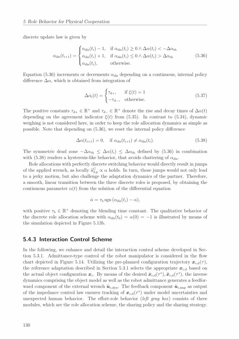
5 Role Behavior for Physical Cooperation
discrete update law is given by
αdis(ti+1) =
αdis(ti)− 1, if αdis(ti) ≥ 0 ∧∆α(ti) < −∆αth
αdis(ti) + 1, if αdis(ti) ≤ 0 ∧∆α(ti) > ∆αth
αdis(ti), otherwise.
(5.36)
Equation (5.36) increments or decrements αdis depending on a continuous, internal policy
difference ∆α, which is obtained from integration of
∆αi(t) =
{
τd+, if ξ(t) = 1
−τd−, otherwise.(5.37)
The positive constants τd+ ∈ R+ and τd− ∈ R+ denote the rise and decay times of ∆α(t)
depending on the agreement indicator ξ(t) from (5.35). In contrast to (5.34), dynamic
weighing is not considered here, in order to keep the role allocation dynamics as simple as
possible. Note that depending on (5.36), we reset the internal policy difference
∆α(ti+1) = 0, if αdis(ti+1) 6= αdis(ti). (5.38)
The symmetric dead zone −∆αth ≤ ∆α(ti) ≤ ∆αth defined by (5.36) in combination
with (5.38) renders a hysteresis-like behavior, that avoids chattering of αdis.
Role allocations with perfectly discrete switching behavior would directly result in jumps
of the applied wrench, as locally uC2,y ∝ α holds. In turn, those jumps would not only lead
to a jerky motion, but also challenge the adaptation dynamics of the partner. Therefore,
a smooth, linear transition between the three discrete roles is proposed, by obtaining the
continuous parameter α(t) from the solution of the differential equation
α = τb sgn (αdis(ti)− α),
with positive τb ∈ R+ denoting the blending time constant. The qualitative behavior of
the discrete role allocation scheme with αdis(t0) = α(0) = −1 is illustrated by means of
the simulation depicted in Figure 5.13b.
5.4.3 Interaction Control Scheme
In the following, we enhance and detail the interaction control scheme developed in Sec-
tion 5.3.1. Admittance-type control of the robot manipulator is considered in the flow
chart depicted in Figure 5.14. Utilizing the pre-planned configuration trajectory xc,d(τ),
the reference adaptation described in Section 5.3.1 selects the appropriate xc,d based on
the actual object configuration xc. By means of the desired xc,d(τ∗), xc,d(τ
∗), the inverse
dynamics comprising the object model as well as the robot admittance generates a feedfor-
ward component of the external wrench uc,dyn. The feedback component uc,imp as output
of the impedance control law ensures tracking of xc,d(τ∗) under model uncertainties and
unexpected human behavior. The effort-role behavior (left gray box ) consists of three
modules, which are the role allocation scheme, the sharing policy and the sharing strategy.
130
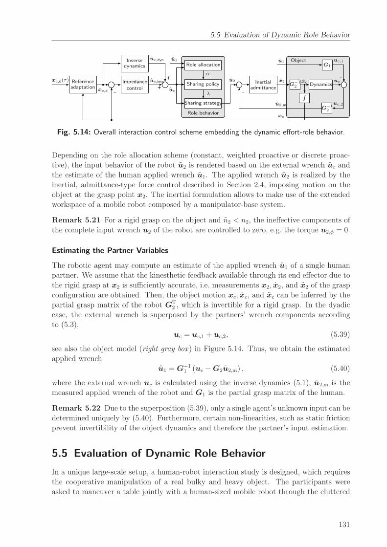
5.5 Evaluation of Dynamic Role Behavior
__
+
+
_
Role allocation
Sharing policy
Sharing strategy
Role behavior
Inversedynamics
Impedance
controlInertial
admittanceReferenceadaptation
Dynamics
Object
α
λ
xc,d(τ)
xc,d
xc
xcx2
u1u1
u2
u2,m
uc,imp
uc,dyn
uc
uc,1
uc,2
uc
∫
G1
G−T2
G−12
Fig. 5.14: Overall interaction control scheme embedding the dynamic effort-role behavior.
Depending on the role allocation scheme (constant, weighted proactive or discrete proac-
tive), the input behavior of the robot u2 is rendered based on the external wrench uc and
the estimate of the human applied wrench u1. The applied wrench u2 is realized by the
inertial, admittance-type force control described in Section 2.4, imposing motion on the
object at the grasp point x2. The inertial formulation allows to make use of the extended
workspace of a mobile robot composed by a manipulator-base system.
Remark 5.21 For a rigid grasp on the object and n2 < n2, the ineffective components of
the complete input wrench u2 of the robot are controlled to zero, e.g. the torque u2,φ = 0.
Estimating the Partner Variables
The robotic agent may compute an estimate of the applied wrench u1 of a single human
partner. We assume that the kinesthetic feedback available through its end effector due to
the rigid grasp at x2 is sufficiently accurate, i.e. measurements x2, x2, and x2 of the grasp
configuration are obtained. Then, the object motion xc, xc, and xc can be inferred by the
partial grasp matrix of the robot GT2 , which is invertible for a rigid grasp. In the dyadic
case, the external wrench is superposed by the partners’ wrench components according
to (5.3),
uc = uc,1 + uc,2, (5.39)
see also the object model (right gray box ) in Figure 5.14. Thus, we obtain the estimated
applied wrench
u1 = G−11 (uc −G2u2,m) , (5.40)
where the external wrench uc is calculated using the inverse dynamics (5.1), u2,m is the
measured applied wrench of the robot and G1 is the partial grasp matrix of the human.
Remark 5.22 Due to the superposition (5.39), only a single agent’s unknown input can be
determined uniquely by (5.40). Furthermore, certain non-linearities, such as static friction
prevent invertibility of the object dynamics and therefore the partner’s input estimation.
5.5 Evaluation of Dynamic Role Behavior
In a unique large-scale setup, a human-robot interaction study is designed, which requires
the cooperative manipulation of a real bulky and heavy object. The participants were
asked to maneuver a table jointly with a human-sized mobile robot through the cluttered
131
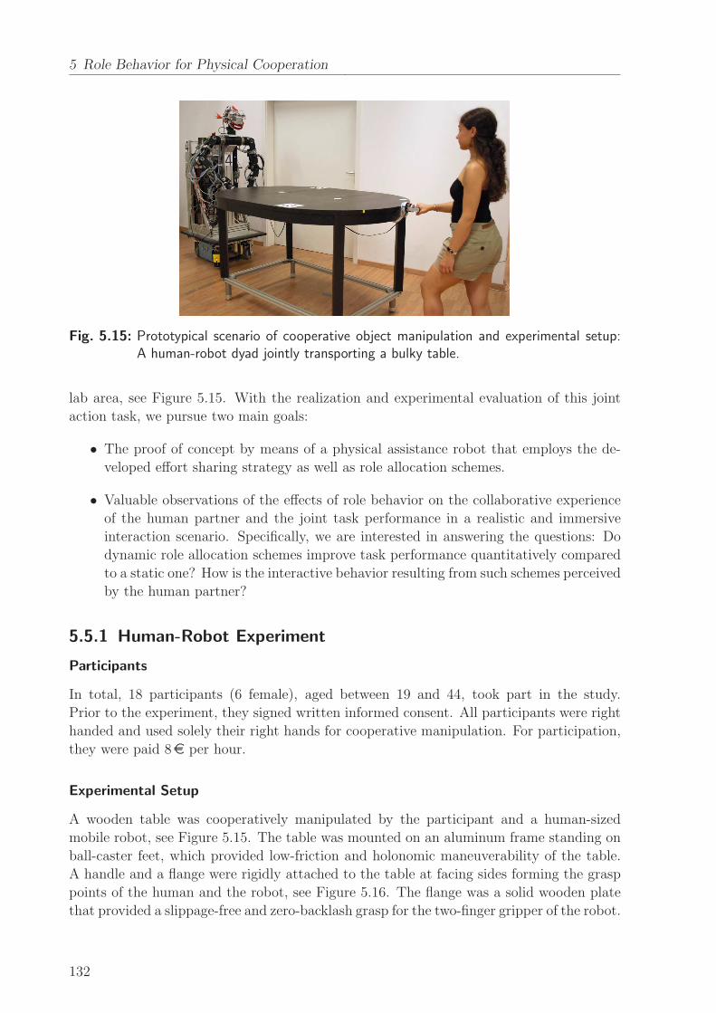
5 Role Behavior for Physical Cooperation
Fig. 5.15: Prototypical scenario of cooperative object manipulation and experimental setup:A human-robot dyad jointly transporting a bulky table.
lab area, see Figure 5.15. With the realization and experimental evaluation of this joint
action task, we pursue two main goals:
• The proof of concept by means of a physical assistance robot that employs the de-
veloped effort sharing strategy as well as role allocation schemes.
• Valuable observations of the effects of role behavior on the collaborative experience
of the human partner and the joint task performance in a realistic and immersive
interaction scenario. Specifically, we are interested in answering the questions: Do
dynamic role allocation schemes improve task performance quantitatively compared
to a static one? How is the interactive behavior resulting from such schemes perceived
by the human partner?
5.5.1 Human-Robot Experiment
Participants
In total, 18 participants (6 female), aged between 19 and 44, took part in the study.
Prior to the experiment, they signed written informed consent. All participants were right
handed and used solely their right hands for cooperative manipulation. For participation,
they were paid 8e per hour.
Experimental Setup
A wooden table was cooperatively manipulated by the participant and a human-sized
mobile robot, see Figure 5.15. The table was mounted on an aluminum frame standing on
ball-caster feet, which provided low-friction and holonomic maneuverability of the table.
A handle and a flange were rigidly attached to the table at facing sides forming the grasp
points of the human and the robot, see Figure 5.16. The flange was a solid wooden plate
that provided a slippage-free and zero-backlash grasp for the two-finger gripper of the robot.
132

5.5 Evaluation of Dynamic Role Behavior
xC
yC
Force/torquesensor
0.5m
0.575
m
0.6m0.72m
Fig. 5.16: Cooperatively manipulated table equipped with a handle and wrench sensor for thehuman (left side) and a grasp flange for the robot (right side). The grasp pointswere at a height of 0.92m over ground.
An off-line estimation of the object dynamics used in (5.22) revealed the parameters of the
table mass matrix
M c = diag(13.5 kgm2, 44 kg, 44 kg).
The table friction f c was considered as a Coulomb-type friction of 14N in total, acting
equally distributed at the table feet.
The human-sized mobile robot described in Appendix A.2.1 and the enhanced interac-
tion control scheme developed in Section 5.4.3 were employed. The inertial admittance of
the robot (2.16) and the object-centered impedance (5.24) were parameterized as follows
regarding the task-relevant DoF:
M r = diag(0.4 kgm2, 20 kg, 20 kg),
Dr = diag(10Nmsrad−1, 100Nsm−1, 100Nsm−1),
Kp = diag(200Nrad−1, 200Nm−1, 200Nm−1),
Kd = diag(50Nmsrad−1, 50Nsm−1, 50Nsm−1).
The reference trajectory of the table configuration xc,d(τ) was taught once before the
experiments through human demonstration. Recording of the required motion data was
performed by the mobile robot, utilizing the sensor readings from its manipulator kinemat-
ics and base odometry. The experimenter was enabled to haptically guide the table-robot
system in arbitrary direction, since the robot rendered a smooth following behavior through
inertial admittance control with respect to its rigid grasp point. Second order low-pass
filtering with 0.4Hz cut-off frequency guaranteed smooth derivatives xc,d(τ) and xc,d(τ).
Conditions
Three conditions manipulated the role behavior of the robot according to the role allocation
schemes synthesized in Section 5.4.2:
133
5 Role Behavior for Physical Cooperation
xc,1(τ)
xc,2(τ)
xc,3(τ)
xc,4(τ)
xc,1xc,2
xc,3
xc,4
H
H
H
H
R
R
R
R
Fig. 5.17: Bird’s eye view of the lab area used in the experiment with four designated parkingconfigurations of the table xc,i. The outer box represents the boundaries of theenvironment spanning a square of approximately 8m× 8m. Gray regions are oc-cupied by obstacles. The dotted curves represent the paths xc,i(τ) connecting theparking configurations.
• CRA: Constant Role Allocation.
The robot contributed to the task without changing its role. It rendered static role
behavior by means of the balanced-effort policy πbal (α = 0) at all times.
• WPRA: Weighted Proactive Role Allocation.
As long as the wrench applied by the human was in the expected direction, or
the human was inactive, the robot increased its policy parameter α(t) gradu-
ally with time. Otherwise, it decreased α(t). In the experiment, we used the
time constants τw+ = 0.02 (Ns)−1 and τw− = 0.04 (Ns)−1. The wrench thresholds
were uCy,th = 10N and uCy,agr = 1N.
• DPRA: Discrete Proactive Role Allocation.
Similar to WPRA, the robot changed its role by increasing or decreasing α(t) grad-
ually. Three discrete roles were rendered by the policies πmin, πbal and πmax. During
the experiment, we used the time constants τd+ = 0.2 s−1 and τd− = 2 s−1, as well
as the blending time constant τb = 2 s−1. The policy difference threshold was set
to ∆αth = 0.6.
Procedure
A trial consisted of moving the table jointly with the robot to three designated parking
configurations xc,i, i ∈ {2, 3, 4}, and then coming back to the initial configuration xc,1, as
shown in Figure 5.17. The overall reference completion time summing the durations of the
four demonstrated trajectory segments was 52 s, with translational peak velocities ranging
within 0.7 − 1.0ms−1. The trial and data collection started with an acoustical signal
134
5.5 Evaluation of Dynamic Role Behavior
presented to the participant. Detailed instructions about the task and the conditions were
given before the experiment. The participants were allowed to apply pushing and pulling
forces using only their right hands by holding the handle of the table. Lifting the table
off the ground and talking during the experiment were prohibited. The positions of the
human and the robot in each of the parking configurations were clearly marked on the
floor of the area. These marks were also shown to the participants before the experiment.
The free space available for maneuvering the table between the parking configurations
was constrained by obstacles in such a way, that ambiguities and alternatives for possible
common paths were avoided.
The conditions (CRA, WPRA, and DPRA) were presented to the participants in per-
muted order using a balanced Latin Square design to avoid learning effects. Under each
condition, the participants performed three trials. After each trial, a small break was given
to initialize the table and robot pose. After performing these three trials successfully, the
participants were given a questionnaire to comment on their experience. Afterwards, they
were presented a new condition.
5.5.2 Evaluation Criteria
Both quantitative and subjective measures deployed for the evaluation are introduced in
the following. The data collected in the first 300ms and in the final leg of segment xc,4 (see
Figure 5.17) is discarded. Force and movement data are low-pass filtered using a first-order
filter with 15Hz cut-off frequency.
Task performance
The completion time CT of each trial is taken as a measure of task performance.
Physical Effort
The per-trial means of the wrench magnitudes applied by the partners, denoted by |uCi,y|,as well as their conducted mechanical work are considered as indicators of the physical
effort made by them. The individual effort is captured by the accumulated work during
the trial
AWi =
∫ CT
0
∣
∣ui,m(t)Txi(t)
∣
∣ dt,
where ui,m denotes the measured wrench exerted by agent i, and xi the velocity of the
corresponding grasp point. The accumulated work done on the table by the partners during
a trial considers the accumulated energy transfer on the table, i.e. how efficiently the table
could be moved to the parking configurations. It is calculated by
AWtable =
∫ CT
0
∣
∣uc(t)Txc(t)
∣
∣ dt,
where the motion-causing external wrench uc(t) is obtained by evaluating (5.3) for the
measured wrenches ui,m(t). Note that the absolute energy flow is accumulated, since the
human partner is assumed not to recoup by absorbing energy, i.e. through breaking actions.
135
5 Role Behavior for Physical Cooperation
Amount of Disagreement
In the cooperative task, disagreement is assumed to occur when the partners pull or push
the table in opposite directions along the yC-axis. Instead of contributing to object motion,
part of the forces in this axis are wasted for compressing or tensioning the table. These
forces are called interactive forces and according to [48] defined as
uI =
uC1,y, if sgn(uC1,y) 6= sgn(uC2,y)
∧ |uC1,y| ≤ |uC2,y|−uC2,y, if sgn(uC1,y) 6= sgn(uC2,y)
∧ |uC1,y| > |uC2,y|0, otherwise.
(5.41)
The quality of cooperation is assessed by weighing the interactive forces as the effect of
disagreement with the time spent in disagreement. Since we are not interested whether
the agents disagree by pushing or pulling against each other (which is indicated by the
sign of uI), we propose the amount of disagreement
AD =
∫ CT
0
|uI(t)| dt,
as measure of cooperation quality. It is calculated based on the magnitude of the interactive
forces (5.41).
Subjective Reasoning
After each condition, the participants were asked to fill in a questionnaire. It consisted of
the set of six questions taken from the NASA task load index (NASA-TLX) [56], as well
as 14 questions developed in [7, 85]. The participants answered on a seven-point Likert
scale. Some of the latter questions were rephrased and asked again within the questionnaire
in arbitrary order, hence the average responses to the rephrased questions is used for the
evaluation. The NASA-TLX evaluates the degree to which each of six factors contribute
to the perceived workload of the task. Those factors are mental, physical and temporal
demand, as well as performance, effort and frustration level. The remaining questions were
asked in the following categories: The extent to which the participants had a sense of
collaboration with the robot during the task (two questions). The level of interaction the
participants experienced during the task (two questions). The level of comfort and pleasure
(each one question). The participants’ perceived degree of control on the movement of the
table (two questions). The predictability of the robotic movements during the task (two
questions). The level of trust in their robotic partner controlling the table (two questions).
Human-likeness, i.e. the extent to which the robotic actions resembled those of a human
being acting in a similar real-life scenario (two questions). The formulations are found in
Appendix C.
136
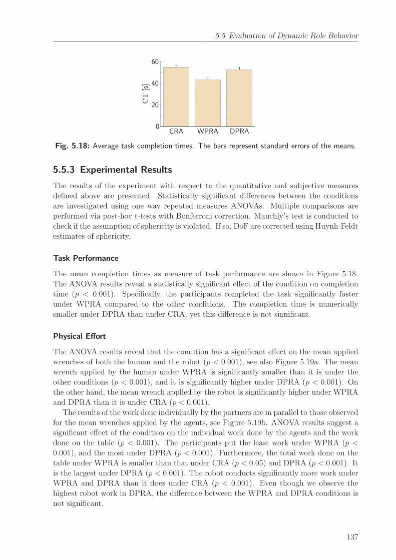
5.5 Evaluation of Dynamic Role Behavior
CRA WPRA DPRA0
20
40
60
CT
[s]
Fig. 5.18: Average task completion times. The bars represent standard errors of the means.
5.5.3 Experimental Results
The results of the experiment with respect to the quantitative and subjective measures
defined above are presented. Statistically significant differences between the conditions
are investigated using one way repeated measures ANOVAs. Multiple comparisons are
performed via post-hoc t-tests with Bonferroni correction. Mauchly’s test is conducted to
check if the assumption of sphericity is violated. If so, DoF are corrected using Huynh-Feldt
estimates of sphericity.
Task Performance
The mean completion times as measure of task performance are shown in Figure 5.18.
The ANOVA results reveal a statistically significant effect of the condition on completion
time (p < 0.001). Specifically, the participants completed the task significantly faster
under WPRA compared to the other conditions. The completion time is numerically
smaller under DPRA than under CRA, yet this difference is not significant.
Physical Effort
The ANOVA results reveal that the condition has a significant effect on the mean applied
wrenches of both the human and the robot (p < 0.001), see also Figure 5.19a. The mean
wrench applied by the human under WPRA is significantly smaller than it is under the
other conditions (p < 0.001), and it is significantly higher under DPRA (p < 0.001). On
the other hand, the mean wrench applied by the robot is significantly higher under WPRA
and DPRA than it is under CRA (p < 0.001).
The results of the work done individually by the partners are in parallel to those observed
for the mean wrenches applied by the agents, see Figure 5.19b. ANOVA results suggest a
significant effect of the condition on the individual work done by the agents and the work
done on the table (p < 0.001). The participants put the least work under WPRA (p <
0.001), and the most under DPRA (p < 0.001). Furthermore, the total work done on the
table under WPRA is smaller than that under CRA (p < 0.05) and DPRA (p < 0.001). It
is the largest under DPRA (p < 0.001). The robot conducts significantly more work under
WPRA and DPRA than it does under CRA (p < 0.001). Even though we observe the
highest robot work in DPRA, the difference between the WPRA and DPRA conditions is
not significant.
137

5 Role Behavior for Physical Cooperation
Human Robot
CRAWPRADPRA
0
10
20
30
|uC i,y|[N]
(a) Mean wrenches applied by the partners.
Human Robot Table
CRAWPRADPRA
0
200
400
600
800
1000
AW
i,AW
table[J]
(b) Work done individually and on the table.
Fig. 5.19: The averaged measures of physical effort under each condition. The bars representstandard errors of the means.
CRA WPRA DPRA
AD
[Ns]
0
40
80
120
Fig. 5.20: The amount of disagreement averaged over all trials under each condition. Thebars represent standard errors of the means.
Amount of Disagreement
The amount of disagreement accumulated under each condition is illustrated in Figure 5.20.
The ANOVA results indicate a significant effect of the condition on the amount of disagree-
ment (p < 0.05). Multiple comparisons imply that the amount of disagreement is similar
under CRA and WPRA, whereas it is lower under DPRA than under CRA (p < 0.001)
and WPRA (p < 0.001). Note that only the signs of the applied wrenches are considered to
decide whether there is a disagreement between the partners. Also, interactive forces < 1N
are not treated as disagreement.
Role Allocation
The policy parameter α(t) is investigated to gain a better understanding of the dynamic
role allocation behavior. In Figure 5.21, the evolution of the role allocation behavior under
WPRA and DPRA is illustrated by means of selected sample trials. Upon examining these
plots, we observe that even though the human wrench profile bears some similarity under
WPRA and DPRA, the robotic role behavior is drastically different. In particular, frequent
transitions of the discrete role under DPRA become obvious, in contrast to the continuous
138
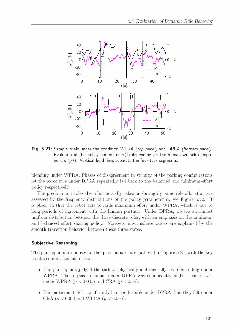
5.5 Evaluation of Dynamic Role Behavior
α
α
uC1,y
uC1,yuC 1,y[N
]uC 1,y[N
]
t [s]
t [s]
αα
0
0
0
0
0
0
0
0
1010
1010
20
20
20
20
20
20
3030
3030
40
40
40
40
40
40
5050
-20
-20
-40
-40
-1
-1
1
1
Fig. 5.21: Sample trials under the condition WPRA (top panel) and DPRA (bottom panel):Evolution of the policy parameter α(t) depending on the human wrench compo-nent uC1,y(t). Vertical bold lines separate the four task segments.
blending under WPRA. Phases of disagreement in vicinity of the parking configurations
let the robot role under DPRA repeatedly fall back to the balanced and minimum-effort
policy respectively.
The predominant roles the robot actually takes on during dynamic role allocation are
assessed by the frequency distributions of the policy parameter α, see Figure 5.22. It
is observed that the robot acts towards maximum effort under WPRA, which is due to
long periods of agreement with the human partner. Under DPRA, we see an almost
uniform distribution between the three discrete roles, with an emphasis on the minimum
and balanced effort sharing policy. Non-zero intermediate values are explained by the
smooth transition behavior between these three states.
Subjective Reasoning
The participants’ responses to the questionnaire are gathered in Figure 5.23, with the key
results summarized as follows:
• The participants judged the task as physically and mentally less demanding under
WPRA. The physical demand under DPRA was significantly higher than it was
under WPRA (p < 0.005) and CRA (p < 0.05).
• The participants felt significantly less comfortable under DPRA than they felt under
CRA (p < 0.01) and WPRA (p < 0.005).
139
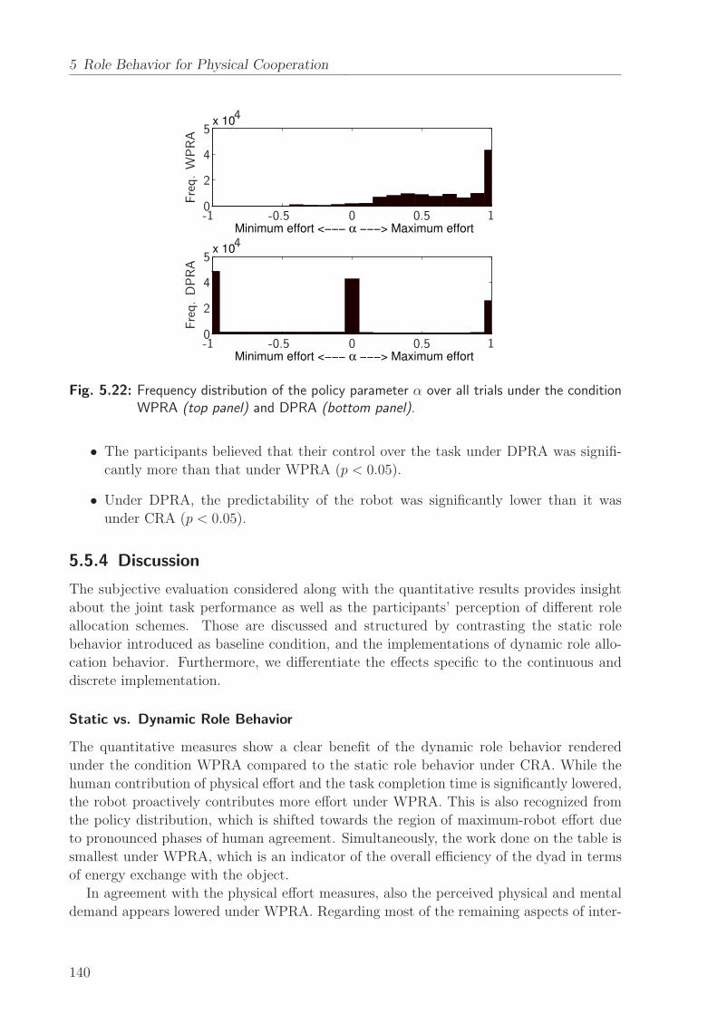
5 Role Behavior for Physical Cooperation
x 10
Minimum effort <−−− α −−−> Maximum effort
x 10
Minimum effort <−−− α −−−> Maximum effort
00
00
-1
-1
-0.5
-0.5
0.5
0.5
1
1
2
2
4
4
4
4
5
5
Freq.WPRA
Freq.DPRA
Fig. 5.22: Frequency distribution of the policy parameter α over all trials under the conditionWPRA (top panel) and DPRA (bottom panel).
• The participants believed that their control over the task under DPRA was signifi-
cantly more than that under WPRA (p < 0.05).
• Under DPRA, the predictability of the robot was significantly lower than it was
under CRA (p < 0.05).
5.5.4 Discussion
The subjective evaluation considered along with the quantitative results provides insight
about the joint task performance as well as the participants’ perception of different role
allocation schemes. Those are discussed and structured by contrasting the static role
behavior introduced as baseline condition, and the implementations of dynamic role allo-
cation behavior. Furthermore, we differentiate the effects specific to the continuous and
discrete implementation.
Static vs. Dynamic Role Behavior
The quantitative measures show a clear benefit of the dynamic role behavior rendered
under the condition WPRA compared to the static role behavior under CRA. While the
human contribution of physical effort and the task completion time is significantly lowered,
the robot proactively contributes more effort under WPRA. This is also recognized from
the policy distribution, which is shifted towards the region of maximum-robot effort due
to pronounced phases of human agreement. Simultaneously, the work done on the table is
smallest under WPRA, which is an indicator of the overall efficiency of the dyad in terms
of energy exchange with the object.
In agreement with the physical effort measures, also the perceived physical and mental
demand appears lowered under WPRA. Regarding most of the remaining aspects of inter-
140
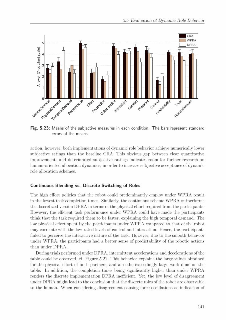
5.5 Evaluation of Dynamic Role Behavior
0
1
2
3
4
5
Answ
er
(7−
pt Lik
ert
scale
)
Men
talD
eman
d
Physica
lDem
and
Tempo
ralD
eman
d
Perfo
rman
ce
Effort
Frustra
tion
Collabo
ratio
n
Inte
raction
Com
fort
Pleas
ure
Con
trol
Predictab
ility
Trust
Hum
anlik
enes
s
CRA
WPRA
DPRA
Fig. 5.23: Means of the subjective measures in each condition. The bars represent standarderrors of the means.
action, however, both implementations of dynamic role behavior achieve numerically lower
subjective ratings than the baseline CRA. This obvious gap between clear quantitative
improvements and deteriorated subjective ratings indicates room for further research on
human-oriented allocation dynamics, in order to increase subjective acceptance of dynamic
role allocation schemes.
Continuous Blending vs. Discrete Switching of Roles
The high effort policies that the robot could predominantly employ under WPRA result
in the lowest task completion times. Similarly, the continuous scheme WPRA outperforms
the discretized version DPRA in terms of the physical effort required from the participants.
However, the efficient task performance under WPRA could have made the participants
think that the task required them to be faster, explaining the high temporal demand. The
low physical effort spent by the participants under WPRA compared to that of the robot
may correlate with the low-rated levels of control and interaction. Hence, the participants
failed to perceive the interactive nature of the task. However, due to the smooth behavior
under WPRA, the participants had a better sense of predictability of the robotic actions
than under DPRA.
During trials performed under DPRA, intermittent accelerations and decelerations of the
table could be observed, cf. Figure 5.21. This behavior explains the large values obtained
for the physical effort of both partners, and also the exceedingly large work done on the
table. In addition, the completion times being significantly higher than under WPRA
renders the discrete implementation DPRA inefficient. Yet, the low level of disagreement
under DPRA might lead to the conclusion that the discrete roles of the robot are observable
to the human. When considering disagreement-causing force oscillations as indication of
141
5 Role Behavior for Physical Cooperation
negotiation processes [133], the participants acted at least in a determinate way in terms
of their applied forces. In agreement with the quantitative results, the subjective measures
indicate a high perceived workload under DPRA. The low-rated levels of predictability
and trust, with similar trends for collaboration, comfort and pleasure, may be the effects
of abrupt role transitions and difficulties in inferring the role transitions of the robot in
advance. As a result of missing predictability, the participants may be driven to being
more dominant in guiding the table, which eventually increases their perceived control
level. Thus, the high physical effort spent by the participants under DPRA may correlate
with the high-rated level of control (with a similar trend for the interaction level).
Implications for Cooperative pHRI Tasks
The aforementioned points draw a clear distinction between the implemented schemes of
dynamic role allocation regarding the domains of pHRI. The discretized version DPRA
invokes distinct and observable role transitions. Such a scheme may be a beneficial alter-
native for interactive training applications. In training, it is necessary for the learner to
recognize the role of the trainer (i.e. the robot), so that he/she can consciously adapt to
it. When the trainer’s role is not perceived, the learner typically tends to obey the guiding
system and does not learn the dynamics of the task [37]. Under the continuous version
WPRA, the human would tend to go along under the supervision of the robot most of
the time, seldom take initiative and hence, fail to gain training experience, cf. the policy
distribution in Figure 5.22.
In many other applications, users would probably prefer comfort over having a strong
sense of control and interaction. For instance, when working with an assisting robot in
a cooperative manipulation task, users would prefer to finish the task in the fastest and
the least demanding way. In such a setting, proactive behavior enforced by a continuous
scheme is expected to be the better alternative, as it evidently increases task performance
and simultaneously lowers human effort.
5.6 Conclusion and Open Issues
Guided by system-theoretic modeling of the cooperative manipulation problem, a novel
strategy for physical effort sharing among human-robot teams is developed. The input
redundancies arising from multiple, spatially distributed grasp points on the common ob-
ject are exploited, and parameterized policies of particular meaning are identified. The
interaction control scheme proposed for embedding of the effort sharing strategy proves
suitable for pHRI, as the participants in our VR experiment could successfully accommo-
date to the resulting static role behavior rendered by the virtual assistant. Although only
little research has been devoted to the role allocation problem in pHRI, a valuable synopsis
of relevant adjustment criteria, policies and interaction control schemes is provided. For
evaluating the utility of dynamic role behavior in a realistic scenario, two role allocation
schemes are synthesized and prototyped. The effort role of a real robotic assistant is al-
located either in a continuous or discrete fashion along the redundant DoF of the task.
Results of the large-scale experimental study show quantitative improvements of the task
142

5.6 Conclusion and Open Issues
performance achieved by the continuous role allocation based on human force feedback.
Yet, the subjective ratings of the participants suggest the constant role allocation to be
preferred.
A number of interesting open issues arise from this work and remain for future research.
The user study on dynamic role behavior shows a clear gap between quantitative perfor-
mance improvement and increased workload perceived by the participants. This trade-off
encourages an iteration of the design process from the analytical perspective: The role
allocation of human dyads may be analyzed in similar scenarios, in order to design the ad-
justment dynamics accordingly. The role allocations synthesized in this chapter focus on a
single instantaneous agreement criterion, which is derived from force feedback in a single
redundant DoF. Further adjustment criteria, as the ones discussed in Section 5.4.1, need
to be integrated into dynamic role allocation schemes. Also, role allocations and possible
interdependencies in multiple redundant DoF are worth to be investigated. Differentiating
the specific influence and meaning of the impedance parameters, i.e. the role-dependent
stiffness and damping imposed by the agents, might be key to a comprehensive under-
standing and modeling of human-robot interactive role behavior. The acquisition of hu-
man partner variables in an on-line and autonomous fashion poses further challenges. For
instance, the emerging field of human-wearable haptic devices highlights promising direc-
tions to locally, but reliably acquire auxiliary kinesthetic feedback from human interaction
partners.
143

6 Conclusions and Future Directions
In this dissertation, an interdisciplinary design methodology on the interactive motor be-
havior of artificial agents is proposed, that enables close joint action of humans and robots.
Despite the inspiring multitude of real world applications, research in this domain is still
in its infancy. The main reasons are the specific challenges arising from motor interaction
with human partners in shared workspaces: Seamless interaction requires actions and reac-
tions to be negotiated on short time scales based on mutual sensory feedback. Erroneous,
unexpected or even slightly delayed motor actions may inevitably break the natural flow
of joint actions or make the task fail completely. For their successful integration in the
human society, the interactive motor capabilities of robot companions must be designed
to be socially compatible and comparable to that of their human interaction partners.
Applicable models of human interactive behavior, and also the conceptual guidelines to
develop them, are rarely found in the existing literature. In a so far unique approach,
this work combines knowledge from human behavioral science, experimental psychology,
system theory and robotics into a holistic design concept. In this chapter, we draw the
conclusions from the analysis and the synthesis of interactive motor behaviors conducted
by means of the design methodology. The potential implications on related research fields
are discussed as well. Finally, a number of promising directions for future research are
given, that follow directly from the considerations in this work.
6.1 Concluding Remarks
Human-oriented design is the core of the methodology characterized in Chapter 2. The
fundamental building blocks of interactive motor behavior are extracted from the main
mechanisms of human joint action. Since the human motor system is known to follow the
common coding principle of perception and action, human behavioral models allow not
only to predict the partner’s actions, but also to make actions predictable to the partner
by employing them in behavior rendering. Therefore, HHI experimental studies and mod-
eling as well as identification techniques are co-designed in the analytical perspective as
the first methodological step. So-derived quantitative models and known behavioral and
system theoretic principles are then integrated to develop interactive motor behavior in
the synthetical perspective as the second methodological step. Prototyping and evaluation
of the synthesized behavior in HRI experiments complete the design process. Due to the
diversity of human motor behaviors and possible interaction scenarios, the design problem
is confined to two relevant classes of dyadic joint action within this thesis. Those are
characterized by visual coordination and visual-haptic cooperation respectively.
The coordination of movements is a frequently encountered basic feature of human
interactive behavior, both intrapersonal and interpersonal. The principle of movement
synchronization is found to be the main enabler of purely rhythmic action coordination.
145
6 Conclusions and Future Directions
With the aim to exploit this human behavioral feature later in human-robot joint action,
the spontaneous visual coordination of goal-directed actions is evidenced and quantified
in Chapter 3. In a new experimental paradigm of rhythmic HHI, spontaneously emerging
synchronization of goal-directed arm movements within human dyads is investigated. The
innovative modeling and identification concept captures the natural dynamics of the inter-
human synchronization behavior in response to an initially applied excitation. Hence, no
additional manipulations are required, that could bias natural HHI. The observed behav-
ioral dynamics and coordination patterns are successfully modeled by the synchronization
dynamics of a pair of cross-coupled phase oscillators. Two meaningful parameters make
the identified behavioral model appealing due to its simplicity as well as its applicability:
The frequency detuning or the natural frequencies of the autonomous oscillator dynam-
ics render the individual urge to proceed the action task, whereas the coupling strength
mediates the interactive motor behavior in response to the partner.
This quantified mechanism of human movement coordination lays the foundations for
the development of synchronization behavior addressed in Chapter 4. Applying the syn-
thetical design perspective, the goal is to equip robotic agents with an intuitive and socially
compatible capability that enables visual coordination in joint action with human partners.
In a novel design concept, a wide range of repetitive joint action tasks is made accessible
to synchronization theory through generic limit cycle representations. Discrete events, e.g.
that of passing zero-velocity points in state space, are known to serve as anchoring points
for human movement synchronization. Based on this behavioral principle, we develop a
variety of enhanced synchronization modes between pairs of heterogeneous limit cycles.
Those coordination patterns are entrained by a unified dynamical process that allows to
synchronize both events and phases simultaneously on a continuous time scale. The inter-
active motor behavior driven by the synchronization concept is successfully evaluated in a
realistic HRI experiment. Objective and subjective measures evidence the efficacy of the
concept towards the goal of intuitive and pleasant joint action with robotic partners.
During physical cooperation, humans are known to apply efficient strategies to negotiate
the effort arising from e.g. jointly manipulated heavy and bulky loads. The interaction
partners dynamically form self-organized and temporally consistent haptic patterns. This
phenomenon called specialization leads to the assignment of situation-specific roles to the
partners. Inspired by the human principle of specialization, interactive motor behavior
for visual-haptic cooperation of human-robot dyads is synthesized in Chapter 5. Starting
point is a system-theoretic modeling concept of the cooperative manipulation problem.
The geometrical properties resulting from spatially distributed grasp points of the part-
ners are utilized to develop an effort sharing strategy based on the redundant components
of the contributions. Meaningful static role behaviors are identified, embedded in an
object-related interaction control scheme and successfully evaluated in a VR experimental
scenario. After discussing first attempts towards role blending, both a continuous and a
discrete variant of dynamical role allocation based on feedback of the human contribution
are synthesized. By means of a human-sized robotic assistant, the interactive role behavior
is evaluated in a realistic joint action task, that requires full-body kinesthetic HRI. Results
evidence a significant increase of the task performance achieved by the robot rendering dy-
namic role behavior, while the subjective feedback encourages further efforts on improving
146
6.2 Outlook
the acceptance of dynamically changing roles.
In the following, we highlight some implications on the involved research fields derived
from the contributions made by this thesis.
Implications on Related Research Fields
The experimental paradigms and designs presented in this thesis provide valuable guidelines
for the further investigation of interactive motor behaviors in HHI and HRI: Variants of the
goal-directed movement task designed in Section 3.2 allow to study the fundamental aspects
of inter-agent motor coordination in a confined setting. The combination of rhythmic and
goal-directed arm movements in a dyadic setting is so far unique. The circular pick and
place task introduced in Section 4.3 provokes realistic motor actions, that involve reaching,
grasping and handing over of objects under coordination constraints. It enables to study
the spatio-temporal aspects of joint action coordination resembling that of real world tasks.
Similarly, the pHRI community is encouraged to complement interaction studies in VR
and small-scale scenarios by immersive full-scale scenarios. The experimental paradigm
of cooperative table pushing employed in Section 5.5 allows an evaluation of prototypical
robotic assistants under realistic conditions regarding the physical properties of bulky
objects and environmental manipulation constraints.
Physical cooperation in joint action tasks is conceptually realized by an object-centered
formulation of the cooperative manipulation problem and human-centered strategies for
dynamic role allocation. Together with the experimental paradigm, the proposed inter-
action control scheme embedding the effort sharing strategy provides a seminal basis and
formal testbed to synthesize and evaluate multi-criteria and multi-dimensional role alloca-
tion schemes.
The synchronization concept based on the unified entrainment process of both contin-
uous phase variables and discrete events provides a valuable contributions to the robotics
community. As an alternative to classical central pattern generators (CPG), it enables to
intuitively and flexibly specify coordinative motor behavior of artificial agents in response
to environmental feedback. Through the phase and event representations, motor coordi-
nation is effectively decoupled from the agent-specific realization of the perception-action
system.
The developed model of human movement coordination may stimulate research and
modeling efforts in the neighboring research field of human social behavior. In particular,
the degree of cross coupling quantified by the human behavioral model may be explored
in its role as an indicator of the partners’ situation-specific weighing between self-centered
autonomous and partner-centered coordinative behavior.
6.2 Outlook
The design process guided by the proposed methodology is successfully run through in
two innovative scenarios of joint action, leading to advanced models of interactive motor
behavior. The promising first achievements of this work, but also the emerged open issues
motivate future research towards seamless HRI in joint action tasks. Some of the most
147
6 Conclusions and Future Directions
interesting points are composed in the following.
The focus of this work is on the executive level of interaction, i.e. how motor actions are
dynamically and bidirectionally adjusted on short time scales to achieve tight coordination.
Yet, the designed behavioral models feature goal-directedness, i.e. they are adjustable in
the spatial domain and compatible with changing task goals. Now that the executive
level of interaction is better understood, the integration of negotiation processes on the
decisive level is believed an important next step towards seamless interaction. Albeit
goal negotiation may be subject to longer time scales in many situations, the cross-effects
between both interaction levels are worth to be explored.
Joint attention is suggested as elementary concept of natural joint action. Further
exploitation of the visual modality by detecting the direction of the partner’s gaze enables
the robot to uncover, which spacial aspects or goals of the task are currently paid attention
by the human. The integration of gaze tracking into future behavior designs as an auxiliary
attention indicator and action predictor is supposed to foster an even tighter shaping of
motor coordination to the partner’s demands and capabilities.
Human-human movement coordination is modeled on a dyadic scope in this work. For
parameter identification, the coupling dynamics within the dyads is assumed isotropic.
Asymmetries, and thus, the coupling strength on an individual scope, could be derived
from the available time series data of the individuals. Promising approaches to scrutinize
the directionality of the coupling dynamics in pairs of bivariate time series data include
methods assessing the direction of information flow and mutual predictability based on
information theory, and the mutual dependencies of the reconstructed individual phase
dynamics. Such approaches will allow a more differentiated view of the individual effort
put into motor adaptation. For example, the coordination effort spent by the human
during joint action with an interactive robotic partner could be assessed.
The insights obtained from both the design of role behavior and synchronization be-
havior suggest, that HRI can be improved further by a design iteration in the analytical
perspective. The concept of movement synchronization opens up the entirely new field of
joint action coordination, in which interactive motor behavior is explored. Although the
behavioral model previously identified in the goal-directed HHI paradigm is integrated into
the design, the synthesized entrainment dynamics are considered only a first, prototypi-
cal realization of such advanced coordination capabilities. Even better matchings of the
human-robot coordination characteristics are expected from a model-directed investiga-
tion of the entrainment behavior of human-human dyads in the deployed joint action task.
Dynamic role behavior is synthesized based on system theory and known behavioral prin-
ciples. Its evaluation in HRI reveals an emerging gap between improved quantitative and
deteriorated subjective measures. The task paradigm of cooperative table pushing allows
to observe the role allocation behavior of human-human dyads in similar study designs.
Besides motion and force, additional behavioral variables, such as the foci of attention,
may be analyzed to gain a more complete picture on their function in the partners’ role
allocation. Time series analysis and system identification are expected to reveal a deeper
understanding of the human role behavior and the fundamental time constants of role
blending.
148

A Experimental Setups
A.1 VR-System for Visual-Haptic Rendering
Displayed scene
Two DoFhaptic
interfaceForce/torque sensor
Fig. A.1: The two DoF VR system used in the experiment described in Section 5.3.3.
The experimental setup of the two DoF haptic interface consists of two linear actuators
mounted on top of a solid rack to allow for comfortable operation while standing in front
of the device, see Figure A.1. A Thrusttube module 2504 (Copley Controls) is orthogonally
mounted on top of a Thrusttube module 2510. The actuators are equipped with optical
position encoders with a resolution of 1µm. Using Xenus XTL (Copley Controls) servo
drivers, the actuators are current controlled. The human force input applied at the rubber-
coated handle is measured using a six DoF wrench sensor 67M25A3-I40-DH (JR3). The
handle is free-spinning, thus rendering zero torques in the vertical axis. For visual feedback
from the virtually rendered scene, a 17 inch TFT-LCD monitor is mounted at eye level of
the operator. The haptic interface is connected to a personal computer equipped with a
Sensoray 626 DAQ card. The entire control scheme is implemented in MATLAB/Simulink
and, using the MATLAB Real-Time Workshop, executed on the Gentoo Linux operating
system with the Real-Time Application Interface (RTAI) [168]. The control algorithm runs
at a frequency of 1 kHz. For rejection of device non-linearities such as friction, the haptic
interface is high-gain position controlled. Visual rendering of the 2D scene is done using
the software libraries provided by the QT UI development framework (Digia).
149
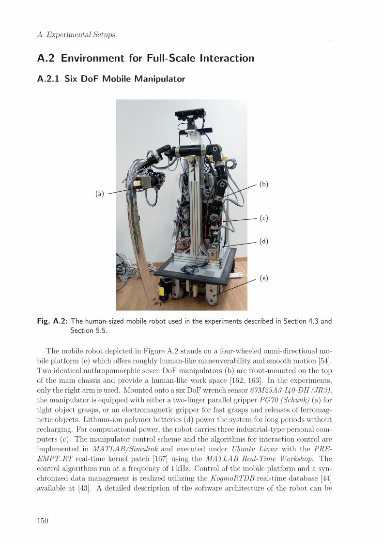
A Experimental Setups
A.2 Environment for Full-Scale Interaction
A.2.1 Six DoF Mobile Manipulator
(a)
(b)
(c)
(d)
(e)
Fig. A.2: The human-sized mobile robot used in the experiments described in Section 4.3 andSection 5.5.
The mobile robot depicted in Figure A.2 stands on a four-wheeled omni-directional mo-
bile platform (e) which offers roughly human-like maneuverability and smooth motion [54].
Two identical anthropomorphic seven DoF manipulators (b) are front-mounted on the top
of the main chassis and provide a human-like work space [162, 163]. In the experiments,
only the right arm is used. Mounted onto a six DoF wrench sensor 67M25A3-I40-DH (JR3),
the manipulator is equipped with either a two-finger parallel gripper PG70 (Schunk) (a) for
tight object grasps, or an electromagnetic gripper for fast grasps and releases of ferromag-
netic objects. Lithium-ion polymer batteries (d) power the system for long periods without
recharging. For computational power, the robot carries three industrial-type personal com-
puters (c). The manipulator control scheme and the algorithms for interaction control are
implemented in MATLAB/Simulink and executed under Ubuntu Linux with the PRE-
EMPT RT real-time kernel patch [167] using the MATLAB Real-Time Workshop. The
control algorithms run at a frequency of 1 kHz. Control of the mobile platform and a syn-
chronized data management is realized utilizing the KogmoRTDB real-time database [44]
available at [43]. A detailed description of the software architecture of the robot can be
150
A.2 Environment for Full-Scale Interaction
found in [5]. During the experiments, all data collection is done by the mobile robot. For
the experiment described in Section 5.5, a second, identical wrench sensor mounted at the
human grasp point of the table is connected to one of the robot PCs. The table configura-
tion as well as the grasp points are tracked using the kinematics model of both the mobile
manipulator and the rigidly grasped object, transformed by the odometry readings of the
mobile base. Through a wireless network connection, the experimenter is able to submit
on-line commands to the robot as required by the experimental procedures.
A.2.2 Motion Capture Systems
Active-Marker Based Tracking
For the experiment described in Section 3.2, a single camera bar of the system Vi-
sualEyez II VZ4000 (PTI PhoeniX Technologies) is used. The camera bar is mounted
overhead at a height of approximately 3m above the work space to be tracked, with the
cameras facing downwards normally and centered around the workspace. Due to single
bar operation, factory calibration of the system guarantees an accuracy < 0.5mm without
custom calibration. The objects to be tracked are equipped with active markers, which are
infrared LEDs of high-power and wide-angle type. During motion capture, these LEDs are
triggered to flash by a wireless target control module, which allows to uniquely identify
the three-dimensional position of the objects. The proprietary software package VZSoft
for controlling the system and gathering motion capture data runs on a Microsoft Win-
dows-based personal computer. The real-time interface of the system provides data at a
frequency of 30Hz for on-line processing through a network connection. In addition, data
are stored simultaneously at a frequency of 200Hz for off-line analysis.
Passive-Marker Based Tracking
The experiment described in Section 4.3 is conducted utilizing a motion capture system
consisting of eleven networked cameras, one Oqus 3+ and ten Oqus 4 (Qualisys). The
cameras are mounted at ceiling height approximately 3m over the work space to be tracked.
They are distributed on a square-shaped frame of approximately 10m × 10m centered
around the work space and aligned to maximize both overlapping of the camera fields
of view and the volume available for tracking. Prior to the experiment, the system is
calibrated within the required work space by means of a manual calibration routine, which
yields an accuracy< 3mm. Passive markers are attached to the objects to be tracked. Ball-
shaped, reflective markers of 12mm and 20mm in diameter are used, which are illuminated
by the infrared spots of the cameras. For unique object identification, a minimum set of
four markers is rigidly attached to each object, forming a unique geometrical configuration.
The software suite Qualisys Track Manager (QTM) for interaction with the motion capture
system runs on a Microsoft Windows-based personal computer. It provides capture data
of the three-dimensional object coordinates at a frequency of 200Hz through the real-time
interface for on-line processing. Capture data are made available to the robot at low
latency through a network connection. Low-pass filtering is applied to the data using a
25-point moving average FIR filter at a sampling rate of 1 kHz.
151
B Haptic Rendering of VR Scenes
B.1 Haptic Interfaces
A haptic interface or haptic display is a mechanical device, typically a robotic manipulator,
that is capable of conveying haptic cues to a human operator [3]. Though haptic displays
addressing the tactile part exist as well, we only consider the kinesthetic part of the haptic
modality and a single interaction point. Pen-shaped or bar-shaped handles, or gloves
attached to the haptic device are utilized frequently to provide the interaction point for the
hand of the human operator. The control method applied to a haptic interface in order to
simulate and display a haptic environment to the human is called haptic rendering. Based
on the preferred rendering scheme, we distinguish two types of haptic interfaces:
• Impedance-type devices measure the motion of the interaction point and display the
forces generated from an impedance-type virtual environment. Inner force control
loops may be employed. Such devices are typically lightweight and highly back-
drivable. They advantageously render low mass dynamics, yet their workspaces and
force output capabilities are mostly rather limited.
• Admittance-type devices measure the forces at the interaction point in addition to
the device motion and display the motion generated from an admittance-type virtual
environment. Typically, the mechanical structure of those devices is solid, heavy
and hardly back-drivable. Inner position or velocity control loops shape the device
dynamics. While such devices may have large workspaces and force capabilities, the
minimum displayable mass is bounded due to stability reasons.
In this work, the focus is on the latter class, since those devices are well-suited to render
the interaction with heavy objects as desired for the investigation of physical effort sharing
presented in Section 5.3.3. An overview on popular haptic devices and their designs is
found in [57, 101].
B.2 Haptic Rendering with Admittance-Type Devices
A variety of control schemes for haptic rendering is found in literature, see [175] for a
detailed classification and discussion of existing approaches. Here, we consider the control
of an admittance-type device for haptic rendering, such as the one in Appendix A.1. The
control scheme is illustrated in Figure B.1. The inner position control loop cancels the
usually nonlinear dynamics of the admittance-type haptic device. In this scheme, a stiff
PD-controller generates the control input up to the motors, which may be supported by
a feedforward compensation of the measured human wrench u1,m and computed-torque
terms. Since the position feedback is usually available with high resolutions and with low
152
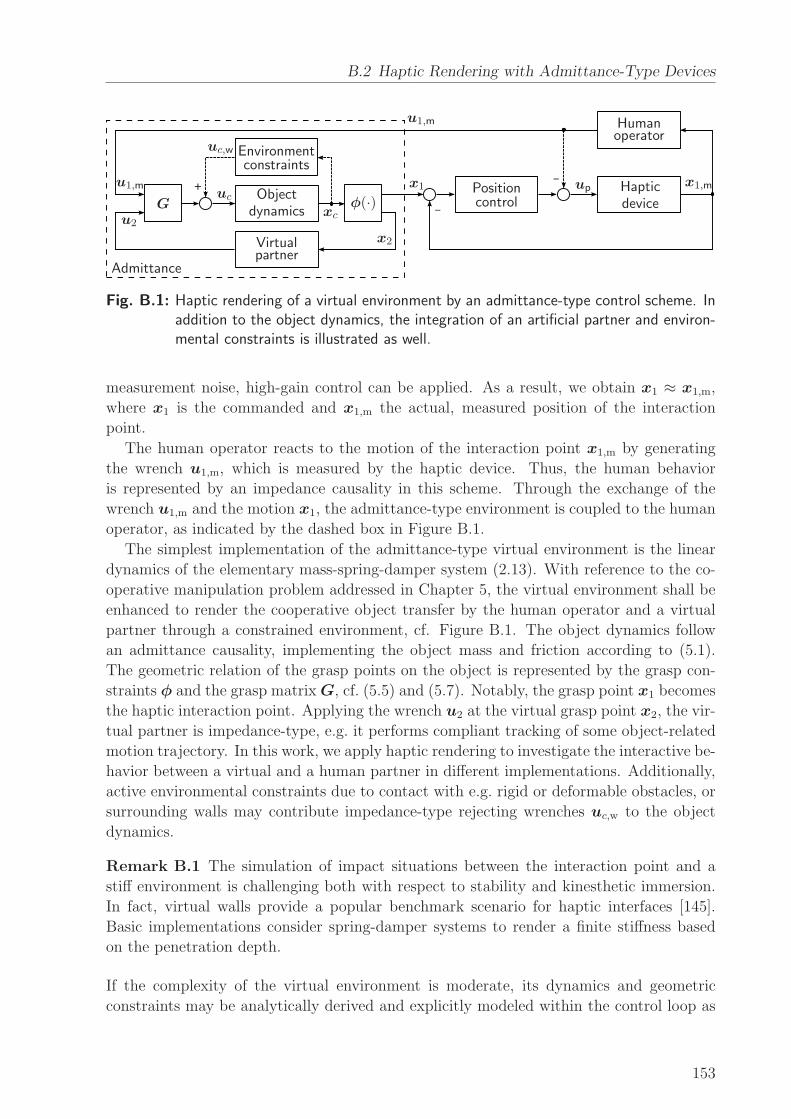
B.2 Haptic Rendering with Admittance-Type Devices
_
_
+
Virtualpartner
Objectdynamics
Environmentconstraints
Positioncontrol
Humanoperator
Hapticdevice
Admittance
u1,m
u1,m
u2
ucup
xc
uc,w
x1 x1,m
x2
G φ(·)
Fig. B.1: Haptic rendering of a virtual environment by an admittance-type control scheme. Inaddition to the object dynamics, the integration of an artificial partner and environ-mental constraints is illustrated as well.
measurement noise, high-gain control can be applied. As a result, we obtain x1 ≈ x1,m,
where x1 is the commanded and x1,m the actual, measured position of the interaction
point.
The human operator reacts to the motion of the interaction point x1,m by generating
the wrench u1,m, which is measured by the haptic device. Thus, the human behavior
is represented by an impedance causality in this scheme. Through the exchange of the
wrench u1,m and the motion x1, the admittance-type environment is coupled to the human
operator, as indicated by the dashed box in Figure B.1.
The simplest implementation of the admittance-type virtual environment is the linear
dynamics of the elementary mass-spring-damper system (2.13). With reference to the co-
operative manipulation problem addressed in Chapter 5, the virtual environment shall be
enhanced to render the cooperative object transfer by the human operator and a virtual
partner through a constrained environment, cf. Figure B.1. The object dynamics follow
an admittance causality, implementing the object mass and friction according to (5.1).
The geometric relation of the grasp points on the object is represented by the grasp con-
straints φ and the grasp matrixG, cf. (5.5) and (5.7). Notably, the grasp point x1 becomes
the haptic interaction point. Applying the wrench u2 at the virtual grasp point x2, the vir-
tual partner is impedance-type, e.g. it performs compliant tracking of some object-related
motion trajectory. In this work, we apply haptic rendering to investigate the interactive be-
havior between a virtual and a human partner in different implementations. Additionally,
active environmental constraints due to contact with e.g. rigid or deformable obstacles, or
surrounding walls may contribute impedance-type rejecting wrenches uc,w to the object
dynamics.
Remark B.1 The simulation of impact situations between the interaction point and a
stiff environment is challenging both with respect to stability and kinesthetic immersion.
In fact, virtual walls provide a popular benchmark scenario for haptic interfaces [145].
Basic implementations consider spring-damper systems to render a finite stiffness based
on the penetration depth.
If the complexity of the virtual environment is moderate, its dynamics and geometric
constraints may be analytically derived and explicitly modeled within the control loop as
153
B Haptic Rendering of VR Scenes
outlined above. Alternatively, software tools for real-time simulation of multi-body physics
are utilized [194], such as the SimMechanics toolbox of MATLAB/Simulink, in order to
efficiently specify more complex virtual environments.
B.3 Visual Rendering of Virtual Environments
Realistic rendering of virtual environments requires visual feedback to the human operator
in congruence with the haptic feedback. To this end, monitors or head-mounted displays
are employed frequently as graphic displays. Due to computational complexity, the visual
rendering scheme is usually implemented to run independently from the physical simula-
tion at update rates around 30Hz. Therefore, the spatial information of moving bodies
such as the object configuration xc is updated based on feedback from the haptic render-
ing scheme. Object silhouettes and workspace boundaries that are composed by simple
geometric primitives and displayed in a two-dimensional scene provide visual guidance to
the human operator when performing planar tasks, e.g. pursuit tracking [33, 195] or con-
strained, goal-directed tasks [89, 105]. Three-dimensional scene rendering is employed to
achieve sufficient feedback and high degrees of immersion in more complex virtual envi-
ronments [7, 31, 194]. The implementation of such scences is eased by various graphics
toolkits available for common programming languages.
154

C Questionnaire
The questionnaire administered in the human-robot experiment for the evaluation of dy-
namic role behavior in Section 5.5 is included below. According to the categories described
in Section 5.5.2, the following statements were rated by the participants:
C.1 Task Load
• Mental demand:
– The task required a large amount of mental and perceptual activity (e.g. think-
ing, deciding, calculating, remembering, looking, searching, etc.).
• Physical demand:
– The task required a large amount of physical activity (e.g. pulling, pushing,
turning, controlling, activating, etc.).
• Temporal demand:
– I felt time pressure due to the rate or pace at which the task occurred.
• Performance:
– I was successful in accomplishing the goals of the task set by the experimenter
(or myself).
• Effort:
– I had to work hard (mentally and physically) to accomplish the task.
• Frustration:
– I felt irritated / stressed / annoyed during the task.
C.2 Task Experience
• Collaboration:
– During the task, the robot and I acted towards a common goal.
– The robot was trying to help me.
• Interaction:
– My communication with the robot was interactive.
– The robot responded to my actions.
155
C Questionnaire
• Comfort:
– I felt comfortable in moving the table with the robot.
• Pleasure:
– The way I interacted with the robot made the task enjoyable.
• Degree of Control:
– The robot did not have control on the movement of the table, but it was only
following my actions.
– I observed and passively obeyed the robot’s actions during the task.
• Predictability:
– I could easily understand what the robot’s plan was during the task.
– The robot was good at predicting what I will do.
• Trust:
– I believed that the robot would perform safely and correctly in moving the table.
– I could trust the robot with moving the table during the task.
• Human-likeness:
– The actions that the robot performed resembled those a human would do on a
similar real-life scenario.
– I felt that the robot behaved like a human being while moving the table with
me.
156
Bibliography
[1] D. Abbink, M. Mulder, and E. Boer. Haptic shared control: smoothly shifting control
authority? Cogn., Technol. & Work, 14(1):19–28, 2012.
[2] J. J. Adam and F. G. Paas. Dwell time in reciprocal aiming tasks. Hum. Mov. Sci.,
15(1):1–24, 1996.
[3] R. J. Adams and B. Hannaford. Stable haptic interaction with virtual environments.
IEEE Trans. Robot. Autom., 15(3):465–474, 1999.
[4] A. Albu-Schaffer, S. Haddadin, C. Ott, A. Stemmer, T. Wimbock, and G. Hirzinger.
The DLR lightweight robot: design and control concepts for robots in human envi-
ronments. Ind. Rob., 34(5):376–385, 2007.
[5] D. Althoff, O. Kourakos, M. Lawitzky, A. Mortl, M. Rambow, F. Rohrmuller,
D. Brscic, D. Wollherr, S. Hirche, and M. Buss. An Architecture for Real-time
Control in Multi-robot Systems. In Cognitive Systems Monographs, pages 43–52.
Springer, 2009.
[6] C. Atkeson, C. An, and J. Hollerbach. Estimation of Inertial Parameters of Manip-
ulator Loads and Links. Int. J. Rob. Res., 5(3):101–119, 1986.
[7] C. Basdogan, C.-H. Ho, M. Srinivasan, and M. Slater. An Experimental Study on
the Role of Touch in Shared Virtual Environments. ACM Trans. Comput.-Hum.
Interact., 7(4):443–460, 2000.
[8] P. Beek, R. Schmidt, A. Morris, M. Sim, and M. Turvey. Linear and nonlinear
stiffness and friction in biological rhythmic movements. Biol. Cybern., 73(6):499–
507, 1995.
[9] P. J. Beek, C. E. Peper, and D. F. Stegeman. Dynamical models of movement
coordination. Hum. Mov. Sci., 14:573–608, 1995.
[10] P. J. Beek, C. E. Peper, and A. Daffertshofer. Modeling Rhythmic Interlimb Coor-
dination: Beyond the Haken-Kelso-Bunz Model. Brain Cogn., 48(1):149–165, 2002.
[11] M. Beetz, F. Stulp, B. Radig, J. Bandouch, N. Blodow, M. Dolha, A. Fedrizzi,
D. Jain, U. Klank, I. Kresse, et al. The assistive kitchen–a demonstration scenario
for cognitive technical systems. In Proc. IEEE Ro-Man, pages 1–8, 2008.
[12] A. Billard, S. Calinon, R. Dillmann, and S. Schaal. Robot Programming by Demon-
stration. In B. Siciliano and O. Khatib, editors, Handbook of Robotics, pages 1371–
1394. Springer, 2008.
157
Bibliography
[13] C. Breazeal. Social interactions in HRI: the robot view. IEEE Trans. Syst. Man
Cybern. C Appl. Rev., 34(2):181–186, 2004.
[14] A. Bruns. Fourier-, Hilbert- and wavelet-based signal analysis: are they really dif-
ferent approaches? J. Neurosci. Methods, 137(2):321–332, 2004.
[15] J. Buchli, L. Righetti, and A. Ijspeert. Engineering entrainment and adaptation in
limit cycle systems. Biol. Cybern., 95(6):645–664, 2006.
[16] E. Burdet, R. Osu, D. W. Franklin, T. E. Milner, and M. Kawato. The central
nervous system stabilizes unstable dynamics by learning optimal impedance. Nat.,
414(6862):446–449, 2001.
[17] T. Chaminade. A Social Cognitive Neuroscience Stance on Human-Robot Interac-
tions. In Int. Conf. SKILLS 2011, volume 1, page 00014, 2011.
[18] A. H. Cohen, P. J. Holmes, and R. H. Rand. The nature of the coupling between
segmental oscillators of the lamprey spinal generator for locomotion: A mathematical
model. J. Math. Biol., 13(3):345–369, 1982.
[19] E. S. Conkur and R. Buckingham. Clarifying the definition of redundancy as used
in robotics. Robotica, 15(5):583–586, 1997.
[20] B. Corteville, E. Aertbelien, H. Bruyninckx, J. D. Schutter, and H. V. Brussel.
Human-inspired Robot Assistant for Fast Point-to-point Movements. In Proc. IEEE
ICRA, pages 3639–3644, 2007.
[21] K. Dautenhahn. Socially intelligent robots: dimensions of human–robot interaction.
Philos. Trans. R. Soc. Lond. B Biol. Sci., 362(1480):679–704, 2007.
[22] A. de Rugy, R. Salesse, O. Oullier, and J.-J. Temprado. A neuro-mechanical model
for interpersonal coordination. Biol. Cybern., 94(6):427–443, 2006.
[23] A. De Santis, B. Siciliano, A. De Luca, and A. Bicchi. An atlas of physical human–
robot interaction. Mechanism and Machine Theory, 43:253–270, 2008.
[24] S. Degallier, C. Santos, L. Righetti, and A. Ijspeert. Movement generation using
dynamical systems : a humanoid robot performing a drumming task. In Proc. IEEE-
RAS Humanoid Robots, pages 512–517, 2006.
[25] D. Delignieres and K. Torre. Event-Based and Emergent Timing: Dichotomy or
Continuum? A Reply to Repp and Steinman (2010). J. Mot. Behav., 43(4):311–318,
2011.
[26] B. Donald, P. Xavier, J. Canny, and J. Reif. Kinodynamic Motion Planning. J.
Assoc. Comput. Mach., 40(5):1048–1066, 1993.
[27] K. Doty, C. Melchiorri, and C. Bonivento. A Theory of Generalized Inverses Applied
to Robotics. Int. J. Robot. Res., 12:1–19, 1993.
158
[28] V. Duchaine and C. M. Gosselin. General model of human-robot cooperation using a
novel velocity based variable impedance control. In Proc. IEEE EuroHaptics, pages
446–451, 2007.
[29] A. Edsinger and C. C. Kemp. Human-robot interaction for cooperative manipulation:
Handing objects to one another. In Proc. IEEE Ro-Man, pages 1167–1172, 2007.
[30] T. Eisenhammer, A. Hubler, N. Packard, and J. A. S. Kelso. Modeling experimental
time series with ordinary differential equations. Biol. Cybern., 65(2):107–112, 1991.
[31] P. Evrard and A. Kheddar. Homotopy Switching Model for Dyad Haptic Interaction
in Physical Collaborative Tasks. In Proc. EHS EuroHaptics, pages 45–50, 2009.
[32] P. Evrard and A. Kheddar. Homotopy-based controller for physical human-robot
interaction. In Proc. IEEE Ro-Man, pages 1–6, 2009.
[33] D. Feth, R. Groten, A. Peer, and M. Buss. Control-theoretic model of haptic human-
human interaction in a pursuit tracking task. In Proc. IEEE Ro-Man, pages 1106–
1111, 2009.
[34] D. Feth, R. Groten, A. Peer, S. Hirche, and M. Buss. Performance Related Energy
Exchange in Haptic Human-Human Interaction in a Shared Virtual Object Manip-
ulation Task. In Proc. EHS EuroHaptics, pages 338–343, 2009.
[35] P. M. Fitts. The information capacity of the human motor system in controlling the
amplitude of movement. J. Exp. Psychol., 47(6):381–391, 1954.
[36] T. Flash and N. Hogan. The coordination of arm movements: An experimentally
confirmed mathematical model. Neurosci., 5:1688–1703, 1985.
[37] B. Forsyth and K. Maclean. Predictive haptic guidance: intelligent user assistance
for the control of dynamic tasks. IEEE Trans. Vis. Comp. Graph., 12(1):103–113,
2006.
[38] D. Franklin, R. Osu, E. Burdet, M. Kawato, and T. Milner. Adaptation to Sta-
ble and Unstable Dynamics Achieved By Combined Impedance Control and Inverse
Dynamics Model. J. Neurophys., 90(5):3270–3282, 2003.
[39] A. Fuchs and J. A. S. Kelso. A theoretical note on models of interlimb coordination.
J. Exp. Psychol. Hum. Percept. Perf., 20(5):1088–1097, 1994.
[40] A. Fuchs, V. Jirsa, H. Haken, and J. A. S. Kelso. Extending the HKB model of
coordinated movement to oscillators with different eigenfrequencies. Biol. Cybern.,
74(1):21–30, 1995.
[41] A. Gams, A. Ijspeert, S. Schaal, and J. Lenarcic. On-line learning and modulation of
periodic movements with nonlinear dynamical systems. Auton. Robots, 27(1):3–23,
2009.
159
Bibliography
[42] R. Gillespie, J. Colgate, and M. Peshkin. A General Framework for Cobot Control.
IEEE Trans. Robot. Automat., 17(4):391–401, 2001.
[43] M. Goebl. KogMo-RTDB - Real-time Database for Cognitive Automobiles, 2012.
URL http://www.kogmo-rtdb.de.
[44] M. Goebl and G. Farber. A Real-Time-capable Hard- and Software Architecture for
Joint Image and Knowledge Processing in Cognitive Automobiles. In Proc. IEEE
IV, pages 734–740, 2007.
[45] J. Goetz, S. Kiesler, and A. Powers. Matching robot appearance and behavior to
tasks to improve human-robot cooperation. In Proc. IEEE Ro-Man, pages 55–60,
2003.
[46] P. G. Griffiths and R. B. Gillespie. Sharing control between humans and automation
using haptic interface: primary and secondary task performance benefits. Hum.
Factors, 47(3):574–590, 2005.
[47] R. Groten. Haptic human-robot collaboration: How to learn from human dyads. PhD
thesis, Technische Universitat Munchen, 2011.
[48] R. Groten, D. Feth, H. Goshy, A. Peer, D. Kenny, and M. Buss. Experimental
Analysis of Dominance in Haptic Collaboration. In Proc. IEEE Ro-Man, pages 723–
729, 2009.
[49] R. Groten, D. Feth, A. Peer, and M. Buss. Shared Decision Making in a Collaborative
Task with Reciprocal Haptic Feedback - an Efficiency-Analysis. In Proc. IEEE ICRA,
2010.
[50] R. Groten, D. Feth, A. Peer, and M. Buss. Psychological experiments in haptic col-
laboration research. In A. Peer and C. D. Giachritsis, editors, Immersive Multimodal
Interactive Presence, Springer Series on Touch and Haptic Systems, pages 65–90.
Springer London, 2012.
[51] S. Haddadin, A. Albu-Schaffer, A. De Luca, and G. Hirzinger. Collision detection
and reaction: A contribution to safe physical human-robot interaction. In Proc.
IEEE/RSJ IROS, pages 3356–3363, 2008.
[52] H. Haken. Synergetics: an introduction : nonequilibrium phase transitions and
self-organization in physics, chemistry and biology. Springer series in synergetics.
Springer-Verlag, 1978.
[53] H. Haken, J. A. S. Kelso, and H. Bunz. A theoretical model of phase transitions in
human hand movements. Biol. Cybern., 51(5):347–356, 1985.
[54] U. Hanebeck, N. Saldic, and G. Schmidt. A Modular Wheel System for Mobile Robot
Applications. In Proc. IEEE/RSJ IROS, pages 17–22, 1999.
[55] M. Hans, B. Graf, and R. Schraft. Robotic home assistant care-o-bot: Past-present-
future. In Proc. IEEE Ro-Man, pages 380–385, 2002.
160
[56] S. G. Hart and L. E. Stavenland. Development of NASA-TLX (Task Load Index):
Results of empirical and theoretical research. In P. A. Hancock and N. Meshkati,
editors, Human Mental Workload, chapter 7, pages 139–183. Elsevier, 1988.
[57] V. Hayward, O. R. Astley, M. Cruz-Hernandez, D. Grant, and G. Robles-De-La-
Torre. Haptic interfaces and devices. Sens. Rev., 24(1):16–29, 2004.
[58] M. Hillman. 2 Rehabilitation Robotics from Past to Present – A Historical Perspec-
tive. In Z. Bien and D. Stefanov, editors, Advances in Rehabilitation Robotics, vol-
ume 306 of Lecture Notes in Control and Information Science, pages 25–44. Springer
Berlin Heidelberg, 2004.
[59] Y. Hirata and K. Kosuge. Distributed Robot Helpers Handling a Single Object in
Cooperation with Human. In Proc. IEEE ICRA, pages 458–463, 2000.
[60] N. Hogan. Impedance control: An approach to manipulation. I–Theory. II–
Implementation. III–Applications. ASME Trans. J. Dyn. Syst. Meas. Control B,
107:1–24, 1985.
[61] N. Hogan and D. Sternad. On rhythmic and discrete movements: reflections, defini-
tions and implications for motor control. Exp. Brain Res., 181(1):13–30, 2007.
[62] J. Holldampf, A. Peer, and M. Buss. Synthesis of an interactive haptic dancing
partner. In Proc. IEEE Ro-Man, pages 527–532, 2010.
[63] M. J. Hove and J. L. Risen. It’s all in the timing: Interpersonal synchrony increases
affiliation. Soc. Cogn., 27(6):949–960, 2009.
[64] G.-C. Hsieh and J. C. Hung. Phase-locked loop techniques. A survey. IEEE Trans.
Ind. Electron., 43(6):609–615, 1996.
[65] M. Huber, H. Radrich, C. Wendt, M. Rickert, A. Knoll, T. Brandt, and S. Glasauer.
Evaluation of a novel biologically inspired trajectory generator in human-robot in-
teraction. In Proc. IEEE Ro-Man, pages 639–644, 2009.
[66] A. J. Ijspeert. 2008 special issue: Central pattern generators for locomotion control
in animals and robots: A review. Neural Netw., 21(4):642–653, 2008.
[67] R. Ikeura, H. Monden, and H. Inooka. Cooperative motion control of a robot and a
human. In Proc. IEEE Ro-Man, pages 112 –117, 1994.
[68] R. Ikeura, T. Moriguchi, and K. Mizutani. Optimal variable impedance control for a
robot and its application to lifting an object with a human. In Proc. IEEE Ro-Man,
pages 500 – 505, 2002.
[69] N. Jarrasse, T. Charalambous, and E. Burdet. A framework to describe, analyze and
generate interactive motor behaviors. PloS ONE, 7(11):e49945, 2012.
[70] N. Jarrasse, V. Sanguineti, and E. Burdet. Slaves no longer: review on role assign-
ment for human-robot joint motor action. Adapt. Behav., 2013.
161
Bibliography
[71] V. K. Jirsa and J. A. S. Kelso. The excitator as a minimal model for the coordination
dynamics of discrete and rhythmic movement generation. J. Mot. Behav., 37(1):35–
51, 2005.
[72] T. Kasuga and M. Hashimoto. Human-robot handshaking using neural oscillators.
In Proc. IEEE ICRA, pages 3802–3807, 2005.
[73] B. A. Kay, J. A. S. Kelso, E. L. Saltzman, and G. Schoner. Space-time behavior
of single and bimanual rhythmical movements: data and limit cycle model. J. Exp.
Psychol. Hum. Percept. Perform., 12(2):178–192, 1987.
[74] J. A. S. Kelso, G. C. de Guzman, C. Reveley, and E. Tognoli. Virtual Partner
Interaction (VPI): Exploring Novel Behaviors via Coordination Dynamics. PLoS
ONE, 4(6):e5749, 2009.
[75] O. Khatib. Mobile manipulation: The robotic assistant. Rob. Auton. Syst., 26(2):
175–183, 1999.
[76] A. Kheddar. Human-robot haptic joint actions Is an equal control-sharing approach
possible? In Proc. IEEE HSI, pages 268–273, 2011.
[77] C. H. Kim, K. Yonekura, H. Tsujino, and S. Sugano. Physical Control of the Rotation
Center of an Unsupported Object-Rope Turning by a Humanoid Robot-. In Proc.
IEEE-RAS Humanoid Robots, pages 148–153, 2009.
[78] A. Kirsch, T. Kruse, E. Sisbot, R. Alami, M. Lawitzky, D. Brscic, S. Hirche, P. Basili,
and S. Glasauer. Plan-Based Control of Joint Human-Robot Activities. Kunstl.
Intell., 24(3):223–231, 2010.
[79] I. Konvalinka, P. Vuust, A. Roepstorff, and C. D. Frith. Follow you, follow me:
Continuous mutual prediction and adaptation in joint tapping. Q. J. Exp. Psychol.,
63(11):2220–2230, 2010.
[80] K. Kosuge and Y. Hirata. Human-Robot Interaction. In Proc. IEEE ROBIO, pages
8–11, 2004.
[81] K. Kosuge, H. Yoshida, and T. Fukuda. Dynamic control for robot-human collabo-
ration. In Proc. IEEE Ro-Man, pages 398–401, 1993.
[82] K. Kosuge, M. Sato, and N. Kazamura. Mobile robot helper. In Proc. IEEE ICRA,
pages 583–588, 2000.
[83] H. Krebs, J. Palazzolo, L. Dipietro, M. Ferraro, J. Krol, K. Rannekleiv, B. Volpe, and
N. Hogan. Rehabilitation Robotics: Performance-Based Progressive Robot-Assisted
Therapy. Auton. Robots, 15(1):7–20, 2003.
[84] T. Kreuz, F. Mormann, R. G. Andrzejak, A. Kraskov, K. Lehnertz, and P. Grass-
berger. Measuring synchronization in coupled model systems: A comparison of dif-
ferent approaches. Phys. D: Nonlinear Phenom., 225(1):29–42, 2007.
162
[85] A. Kucukyilmaz, M. Sezgin, and C. Basdogan. Conveying Intentions through Haptics
in Human-Computer Collaboration. In Proc. IEEE WHC, pages 421–426, June 2011.
[86] A. Kucukyilmaz, T. Sezgin, and C. Basdogan. Intention Recognition for Dynamic
Role Exchange in Haptic Collaboration. IEEE Trans. Haptics, 6(1):58–68, 2013.
[87] Y. Kuramoto. Chemical Oscillations, Waves and Turbulence. Springer, Heidelb.,
1984.
[88] M. Lawitzky, J. R. Medina, D. Lee, and S. Hirche. Feedback motion planning and
learning from demonstration in physical robotic assistance: differences and synergies.
In Proc. IEEE/RSJ IROS, pages 3646–3652, 2012.
[89] M. Lawitzky, M. Kimmel, P. Ritzer, and S. Hirche. Trajectory generation under the
least action principle for physical human-robot cooperation. In Proc. IEEE ICRA,
pages 4285–4290, 2013.
[90] D. Lee and C. Ott. Incremental kinesthetic teaching of motion primitives using the
motion refinement tube. Auton. Robot., pages 1–17, 2011.
[91] S. Lee, S.-Y. Yi, J.-O. Park, and C.-W. Lee. Reference adaptive impedance control
and its application to obstacle avoidance trajectory planning. In Proc. IEEE/RSJ
IROS, pages 1158–1162, 1997.
[92] S. Lee, K. Lee, S. Lee, J. Kim, and C. Han. Human-robot cooperation control for
installing heavy construction materials. Auton. Robots, 22(3):305–319, 2007.
[93] L. Ljung. System identification: Theory for the user. Prentice Hall, Upper Saddle
River, 1999.
[94] L. Ljung and T. Glad. Modeling of Dynamic Systems. PTR Prentice Hall, 1994.
[95] S. M. Lopresti-Goodman, M. J. Richardson, P. L. Silva, and R. C. Schmidt. Period
basin of entrainment for unintentional visual coordination. J. Mot. Behav., 40(1):
3–10, 2008.
[96] J. Lumsden, L. K. Miles, M. J. Richardson, C. A. Smith, and C. N. Macrae. Who
syncs? Social motives and interpersonal coordination. J. Exp. Soc. Psychol., 48(3):
746–751, 2012.
[97] Y. Maeda, T. Hara, and T. Arai. Human-Robot Cooperative Manipulation with
Motion Estimation. In Proc. IEEE/RSJ IROS, pages 2240–2245, 2001.
[98] Y. Maeda, A. Takahashi, T. Hara, and T. Arai. Human-robot cooperation with
mechanical interaction based on rhythm entrainment-realization of cooperative rope
turning. In Proc. IEEE ICRA, pages 3477–3482, 2001.
[99] Y. Maeda, A. Takahashi, T. Hara, and T. Arai. Human-robot Cooperative Rope
Turning–an example of mechanical coordination through rythm entrainment. Adv.
Robotics, 17(1):67–78, 2003.
163
Bibliography
[100] L. Marin, J. Issartel, and T. Chaminade. Interpersonal motor coordination: From
human-human to human-robot interactions. Interact. Stud., 10(3):479–504, 2009.
[101] J. Martin and J. Savall. Mechanisms for haptic torque feedback. In Proc. IEEE
Eurohaptics, pages 611–614, 2005.
[102] K. Matsuoka. Sustained oscillations generated by mutually inhibiting neurons with
adaptation. Biol. Cybern., 52(6):367–376, 1985.
[103] D. T. McRuer and H. R. Jex. A review of quasi-linear pilot models. IEEE Trans.
Hum. Factors Electron., HFE-8(3):231–249, 1967.
[104] J. R. Medina, D. Lee, and S. Hirche. Risk-sensitive optimal feedback control for
haptic assistance. In IEEE ICRA, pages 1025–1031, 2012.
[105] J. R. Medina, T. Lorenz, D. Lee, and S. Hirche. Disagreement-aware physical as-
sistance through risk-sensitive optimal feedback control. In Proc. IEEE/RSJ IROS,
pages 3639–3645, 2012.
[106] M. P. Michalowski, S. Sabanovic, and H. Kozima. A dancing robot for rhythmic
social interaction. In Proc. ACM/IEEE HRI, pages 89–96, 2007.
[107] L. K. Miles, L. K. Nind, and C. N. Macrae. The rhythm of rapport: Interpersonal
synchrony and social perception. J. Exp. Soc. Psychol., 45(3):585–589, 2009.
[108] S. Miossec and A. Kheddar. Human motion in cooperative tasks: Moving object
case study. In Proc. IEEE ROBIO, pages 1509–1514, 2008.
[109] Y. Miyake. Interpersonal synchronization of body motion and the walk-mate walking
support robot. IEEE Trans. Rob., 25(3):638–644, 2009.
[110] R. R. Murphy. Human-robot interaction in rescue robotics. IEEE Trans. Syst. Man
Cybern. C Appl. Rev., 34(2):138–153, 2004.
[111] R. Murray, Z. Li, and S. Sastry. A mathematical introduction to robotic manipulation,
chapter Multifingered Hand Kinematics. CRC Press, 1994.
[112] N. Nitzsche, U. Hanebeck, and G. Schmidt. Design Issues of Mobile Haptic Interfaces.
J. Robot. Syst., 20(9):549–556, 2003.
[113] O. Oguz, A. Kucukyilmaz, T. Sezgin, and C. Basdogan. Haptic Negotiation and
Role Exchange for Collaboration in Virtual Environments. In Proc. IEEE Haptics,
pages 371–378, 2010.
[114] M. Okada, K. Tatani, and Y. Nakamura. Polynomial design of the nonlinear dynamics
for the brain-like information processing of whole body motion. In Proc. IEEE ICRA,
pages 1410–1415, 2002.
[115] R. Olfati-Saber, A. Fax, and R. Murray. Consensus and Cooperation in Networked
Multi-Agent Systems. Proc. IEEE, 95:215–233, 2007.
164
[116] M. K. O’Malley, A. Gupta, M. Gen, and Y. Li. Shared control in haptic systems for
performance enhancement and training. Trans. ASME J. Dyn. Syst. Meas. Control,
128(1):75, 2006.
[117] O. Oullier, G. C. De Guzman, K. J. Jantzen, J. Lagarde, and J. A. S. Kelso. Social
coordination dynamics: Measuring human bonding. Soc. neurosci., 3(2):178–192,
2008.
[118] C. Parker and E. Croft. Experimental investigation of human-robot cooperative
carrying. In Proc. IEEE/RSJ IROS, pages 3361–3366, 2011.
[119] C. A. Parker and E. A. Croft. Design & Personalization of a Cooperative Carrying
Robot Controller. In Proc. IEEE ICRA, pages 3916–3921, 2012.
[120] L. Parker. Distributed Intelligence: Overview of the Field and its Application in
Multi-Robot Systems. J. Phys. Agents, 2:5–14, 2008.
[121] C. Passenberg, A. Peer, and M. Buss. A survey of environment-, operator-, and task-
adapted controllers for teleoperation systems. Mechatronics, 20(7):787–801, 2010.
[122] C. Passenberg, R. Groten, A. Peer, and M. Buss. Towards real-time haptic assistance
adaptation optimizing task performance and human effort. In Proc. IEEE WHC,
pages 155 –160, 2011.
[123] C. Passenberg, A. Glaser, and A. Peer. Exploring the Design Space of Haptic Assis-
tants: the Assistance Policy Module. IEEE Trans. Haptics, 6(4):440–452, 2013.
[124] R. A. Peterson. Constructing effective questionnaires. Sage, 2000.
[125] T. Petric, A. Gams, A. J. Ijspeert, and L. Zlajpah. On-line frequency adaptation and
movement imitation for rhythmic robotic tasks. Int. J. Rob. Res., 30(14):1775–1788,
2011.
[126] A. Pikovsky, M. Rosenblum, and J. Kurths. Synchronization - A universal concept
in nonlinear sciences. Cambridge University Press, Cambridge, 2001.
[127] D. Pongas, A. Billard, and S. Schaal. Rapid synchronization and accurate phase-
locking of rhythmic motor primitives. In Proc. IEEE/RSJ IROS, pages 2911–2916,
2005.
[128] D. Prattichizzo and J. Trinkle. Grasping. In B. Siciliano and O. Khatib, editors,
Springer Handbook of Robotics. Springer, Berlin, Heidelberg, 2008.
[129] R. Quian Quiroga, T. Kreuz, and P. Grassberger. Event synchronization: A simple
and fast method to measure synchronicity and time delay patterns. Phys. Rev. E,
66(4):041904, 2002.
[130] M. Rahman, R. Ikeura, and K. Mizutani. Cooperation characteristics of two humans
in moving an object. Mach. Intell. Robot. Control, 4(2):43–48, 2002.
165
Bibliography
[131] R. H. Rand, A. H. Cohen, and P. J. Holmes. Neural Control of Rythmic Movement
in Vertebrates, chapter Systems of Coupled Oscillators as Models of Central Pattern
Generators. Wiley, New York, 1988.
[132] K. Reed and M. Peshkin. Physical Collaboration of Human-Human and Human-
Robot Teams. IEEE Trans. Haptics, 1(2):108–120, 2008.
[133] K. Reed, M. Peshkin, M. Hartmann, E. Colgate, and J. Patton. Kinesthetic Inter-
action. In Proc. IEEE ICORR, pages 569–574, 2005.
[134] K. Reed, M. Peshkin, M. Hartmann, J. Patton, P. Vishton, and M. Grabowecky.
Haptic cooperation between people, and between people and machines. In Proc.
IEEE/RSJ IROS, pages 2109–2114, 2006.
[135] B. H. Repp. Sensorimotor synchronization: A review of the tapping literature. Psy-
chon. Bull. Rev., 12(6):969–992, 2005.
[136] B. H. Repp and S. R. Steinman. Simultaneous Event-Based and Emergent Timing:
Synchronization, Continuation, and Phase Correction. J. Mot. Behav., 42(2):111–
126, 2010.
[137] B. H. Repp and Y.-H. Su. Sensorimotor synchronization: A review of recent research
(2006-2012). Psychon. Bull. Rev., 20(3):403–452, 2013.
[138] M. J. Richardson, K. L. Marsh, and R. C. Schmidt. Effects of visual and verbal inter-
action on unintentional interpersonal coordination. J. Exp. Psychol. Hum. Percept.
Perform., 31(1):62–79, 2005.
[139] M. J. Richardson, K. L. Marsh, R. W. Isenhower, J. R. L. Goodman, and R. C.
Schmidt. Rocking together: Dynamics of intentional and unintentional interpersonal
coordination. Hum. Mov. Sci., 26(6):867–891, 2007.
[140] B. Robins, E. Ferrari, and K. Dautenhahn. Developing scenarios for robot assisted
play. In Proc. IEEE Ro-Man, pages 180–186, 2008.
[141] L. Rosenberg. Virtual fixtures: Perceptual tools for telerobotic manipulation. In
Proc. IEEE VR, pages 76 –82, 1993.
[142] M. Rosenblum and J. Kurths. Nonlinear Analysis of Physiological Data, chapter
Analysing Synchronization Phenomena from Bivariate Data by Means of the Hilbert
Transform, pages 91–99. Springer, Heidelb., 2007.
[143] M. Rosenblum, A. Pikovsky, J. Kurths, C. Schafer, and P. Tass. Chapter 9 Phase
synchronization: From theory to data analysis. In F. Moss and S. Gielen, editors,
Neuro-Informatics and Neural Modelling, volume 4 of Handbook of Biological Physics,
pages 279 – 321. North-Holland, 2001.
[144] M. Saida, J. R. Medina, and S. Hirche. Adaptive attitude design with risk-sensitive
optimal feedback control in physical human-robot interaction. In Proc. IEEE Ro-
Man, pages 955–961, 2012.
166
[145] K. Salisbury, F. Conti, and F. Barbagli. Haptic rendering: introductory concepts.
IEEE Comput. Graph. Appl., 24(2):24–32, 2004.
[146] A. Salleh, R. Ikeura, S. Hayakawa, and H. Sawai. Cooperative Object Transfer: Effect
of Observing Different Part of the Object on the Cooperative Task Smoothness. J.
Biomech. Sci. Eng., 6(4):343–360, 2011.
[147] T. Sato, M. Hashimoto, and M. Tsukahara. Synchronization based control using
online design of dynamics and its application to human-robot interaction. In Proc.
IEEE ROBIO, pages 652–657, 2007.
[148] R. Schmidt and M. T. Turvey. Phase-entrainment dynamics of visually coupled
rhythmic movements. Biol. Cybern., 70(4):369–376, 1994.
[149] R. Schmidt, P. Fitzpatrick, R. Caron, and J. Mergeche. Understanding social motor
coordination. Hum. Mov. Sci., 30(5):834–845, 2011.
[150] R. C. Schmidt and B. O’Brien. Evaluating the Dynamics of Unintended Interpersonal
Coordination. Ecol. Psychol., 9(3):189–206, 1997.
[151] R. C. Schmidt, C. Carello, and M. T. Turvey. Phase transitions and critical fluc-
tuations in the visual coordination of rhythmic movements between people. J. Exp.
Psychol. Hum. Percept. Perform., 16(2):227–247, 1990.
[152] R. C. Schmidt, B. K. Shaw, and M. T. Turvey. Coupling Dynamics in Interlimb
Coordination. J. Exp. Psychol. Hum. Percept. Perform., 19(2):397–415, 1993.
[153] R. C. Schmidt, M. Bienvenu, P. A. Fitzpatrick, and P. G. Amazeen. A comparison
of intra- and interpersonal interlimb coordination: coordination breakdowns and
coupling strength. J. Exp. Psychol. Hum. Percept. Perform., 24(3):884–900, 1998.
[154] S. Schneider and R. Cannon. Object Impedance Control for Cooperative Manip-
ulation: Theory and Experimental Results. IEEE Trans. Robot. Automat., 8(3):
383–394, 1992.
[155] G. Schoner and J. A. Kelso. Dynamic pattern generation in behavioral and neural
systems. Sci., 239(4847):1513–1520, 1988.
[156] A. Schubo, C. Vesper, M. Wiesbeck, and S. Stork. HCI and Usability for Medicine
and Health Care, Lecture Notes in Computer Science, volume 4799, chapter Move-
ment C, pages 143–154. Springer Berlin / Heidelberg, 2007.
[157] N. Sebanz and G. Knoblich. Prediction in joint action: what, when, and where. Top.
Cogn. Sci., 1(2):353–367, 2009.
[158] N. Sebanz, H. Bekkering, and G. Knoblich. Joint action: bodies and minds moving
together. Trends Cogn. Sci., 10(2):70–76, 2006.
167
Bibliography
[159] B. Sellner, F. W. Heger, L. M. Hiatt, R. Simmons, and S. Singh. Coordinated
multiagent teams and sliding autonomy for large-scale assembly. Proc. IEEE, 94(7):
1425–1444, 2006.
[160] D. A. Smirnov and R. G. Andrzejak. Detection of weak directional coupling: Phase-
dynamics approach versus state-space approach. Phys. Rev. E, 71(3):36207, 2005.
[161] G. Sofianidis, V. Hatzitaki, G. Grouios, L. Johannsen, and A. Wing. Somatosensory
driven interpersonal synchrony during rhythmic sway. Hum. Mov. Sci., 31(3):553 –
566, 2012.
[162] B. Stanczyk. Developement and Control of an Anthropomorphic Telerobotic System.
PhD thesis, Technische Universitat Munchen, 2006.
[163] B. Stanczyk and M. Buss. Development of a Telerobotic System for Exploration of
Hazardous Environments. In Proc. IEEE/RSJ IROS, pages 2532–2537, 2004.
[164] B. E. Studenka and H. N. Zelaznik. Synchronization in repetitive smooth movement
requires perceptible events. Acta Psychol., 136(3):432 – 441, 2011.
[165] T. Takubo, H. Arai, Y. Hayashibara, and K. Tanie. Human-Robot Cooperative
Manipulation Using a Virtual Nonholonomic Constraint. Int. J. Robot. Res., 21:
541–553, 2002.
[166] J. Tan, N. Xi, and Y. Wang. Integrated task planning and control for mobile ma-
nipulators. Int. J. Rob. Res., 22(5):337–354, 2003.
[167] The Preempt RT community. Real-Time Linux Wiki, 2013. URL http://rt.wiki.
kernel.org.
[168] The RTAI Team. RTAI - the RealTime Application Interface for Linux, 2013. URL
www.rtai.org.
[169] A. Thobbi, Y. Gu, and W. Sheng. Using Human Motion Estimation for Human-
Robot Cooperative Manipulation. In Proc. IEEE/RSJ IROS, pages 2873–2878, 2011.
[170] E. Todorov. Optimality principles in sensorimotor control. Nat. neurosci., 7(9):
907–915, 2004.
[171] K. Torre and R. Balasubramaniam. Two different processes for sensorimotor syn-
chronization in continuous and discontinuous rhythmic movements. Exp. Brain Res.,
199(2):157–166, 2009.
[172] T. Tsumugiwa, T. Yokogawa, and K. Hara. Variable Impedance Control Based
on Estimation of Human Arm Stiffness for Human-Robot Cooperative Calligraphic
Task. In Proc. IEEE ICRA, pages 644–650, 2002.
[173] M. T. Turvey, L. D. Rosenblum, R. C. Schmidt, and P. N. Kugler. Fluctuations
and Phase Symmetry in Coordinated Rhythmic Movements. J. Exp. Psychol. Hum.
Percept. Perform., 12(4):564–583, 1986.
168
[174] T. Ubukata, S. Kotosaka, and H. Ohtaki. Trajectory Generation for Adaptive Motion
by Phase Feedback - Synchronization of Multicycle Human Movement. J. Robotics
and Mechatronics, 21(3):342–352, 2009.
[175] M. Ueberle and M. Buss. Control of kinesthetic haptic interfaces. In Proc. IEEE/RSJ
IROS, Workshop on Touch and Haptics, 2004.
[176] U. Unterhinninghofen, T. Schauß, and M. Buss. Control of a Mobile Haptic Interface.
In Proc. IEEE ICRA, pages 2085–2090, 2008.
[177] P. Valdesolo, J. Ouyang, and D. DeSteno. The rhythm of joint action: Synchrony
promotes cooperative ability. J. Exp. Soc. Psychol., 46(4):693–695, 2010.
[178] N. R. van Ulzen, C. J. C. Lamoth, A. Daffertshofer, G. R. Semin, and P. J. Beek.
Characteristics of instructed and uninstructed interpersonal coordination while walk-
ing side-by-side. Neurosci. Lett., 432(2):88–93, 2008.
[179] M. Varlet and M. J. Richardson. Computation of continuous relative phase and
modulation of frequency of human movement. J. Biomech., 44(6):1200–4, 2011.
[180] C. Vesper, A. Soutschek, and A. Schubo. Motion coordination affects movement
parameters in a joint pick-and-place task. Q. J. Exp. Psychol., 62(12):2418–2432,
2009.
[181] C. Vesper, S. Butterfill, G. Knoblich, and N. Sebanz. A minimal architecture for
joint action. Neural Netw., 23(8):998–1003, 2010.
[182] J. Wainer, D. J. Feil-Seifer, D. A. Shell, and M. J. Mataric. Embodiment and human-
robot interaction: A task-based perspective. In Proc. IEEE Ro-Man, pages 872–877,
2007.
[183] Z. Wang, J. Yuan, and M. Buss. Modelling of human haptic skill: A framework and
preliminary results. In Proc. IFAC, pages 14761–14766, 2008.
[184] Z. Wang, A. Peer, and M. Buss. An HMM approach to realistic haptic human-robot
interaction. In Proc. IEEE EuroHaptics, pages 374–379, 2009.
[185] W. H. Warren. The Dynamics of Perception and Action. Psychol. Rev., 113(2):
358–389, 2006.
[186] A. Weiss, R. Bernhaupt, M. Tscheligi, D. Wollherr, K. Kuhnlenz, and M. Buss. A
methodological variation for acceptance evaluation of human-robot interaction in
public places. In Proc. IEEE Ro-Man, pages 713–718, 2008.
[187] A. D. Wilson, D. R. Collins, and G. P. Bingham. Perceptual coupling in rhythmic
movement coordination: stable perception leads to stable action. Exp. Brain Res.,
164(4):517–528, 2005.
[188] A. M. Wing and A. Kristofferson. Response delays and the timing of discrete motor
responses. Percept. Psychophys., 14(1):5–12, 1973.
169
Bibliography
[189] T. Wojtara, M. Uchihara, H. Murayama, S. Shimoda, S. Sakai, H. Fujimoto, and
H. Kimura. Human-robot collaboration in precise positioning of a three-dimensional
object. Automatica, 45(2):333–342, 2009.
[190] H. A. Yanco and J. L. Drury. A taxonomy for human-robot interaction. In Proc.
AAAI Fall Symposium on Human-Robot Interaction, pages 111–119, 2002.
[191] H. Yu, M. Spenko, and S. Dubowsky. An Adaptive Shared Control System for an
Intelligent Mobility Aid for the Elderly. Auton. Robots, 15(1):53–66, 2003.
[192] X. Zhang and M. Hashimoto. SBC for motion assist using neural oscillator. In Proc.
IEEE ICRA, pages 659–664, 2009.
[193] A. Z. Zivotofsky and J. M. Hausdorff. The sensory feedback mechanisms enabling
couples to walk synchronously: An initial investigation. J. NeuroEng. Rehabil., 4(1):
28, 2007.
Own Related Publications
[194] P. Donner, A. Mortl, S. Hirche, and M. Buss. Human-Robot Cooperative Object
Swinging. In Proc. IEEE ICRA, pages 4328–4334, 2013.
[195] M. Lawitzky, A. Mortl, and S. Hirche. Load Sharing in Human-Robot Cooperative
Manipulation. In Proc. IEEE Ro-Man, pages 185–191, 2010.
[196] T. Lorenz, A. Mortl, B. Vlaskamp, A. Schubo, and S. Hirche. Synchronization in
a goal-directed task: human movement coordination with each other and robotic
partners. In Proc. IEEE Ro-Man, pages 198–203, 2011.
[197] T. Lorenz, A. Mortl, and S. Hirche. Movement synchronization fails during non-
adaptive human-robot interaction. In Proc. ACM/IEEE HRI, pages 189–190, 2013.
[198] T. Lorenz, B. N. S. Vlaskamp, A.-M. Kasparbauer, A. Mortl, and S. Hirche. Dyadic
movement synchronization while performing incongruent trajectories requires mutual
adaptation. Front. Hum. Neurosci., 8(461), 2014.
[199] J. Medina, M. Lawitzky, A. Mortl, D. Lee, and S. Hirche. An Experience-Driven
Robotic Assistant Acquiring Human Knowledge to Improve Haptic Cooperation. In
Proc. IEEE/RSJ IROS, pages 2416–2422, 2011.
[200] A. Mortl, M. Lawitzky, A. Kucukyilmaz, M. Sezgin, C. Basdogan, and S. Hirche.
The Role of Roles: Physical Cooperation between Humans and Robots. Int. J. Rob.
Res., 31(13):1656–1674, 2012.
[201] A. Mortl, T. Lorenz, B. Vlaskamp, A. Gusrialdi, A. Schubo, and S. Hirche. Modeling
inter-human movement coordination: synchronization governs joint task dynamics.
Biol. Cybern., 106(4):241–259, 2012.
[202] A. Mortl, T. Lorenz, and S. Hirche. Rhythm Patterns Interaction – Synchronization
Behavior for Human-Robot Joint Action. PLOS ONE, 9(4):e95195, 2014.
170