design of grc panels’ fixingomarhadri.me/gfrc_design_sample.pdf4.1. column bases hc-sr-2.2: this...
TRANSCRIPT

Project St. Rigs Hotel
Job Ref.
Water Wheel
Structure GRC Curtain walls
Part of Structure Podium
Sheet no./rev. 5 /a
Dubai Investment Park Tel: 04-3974618 Fax: 04-3974617
email: [email protected]
Calc. by
Date
18-Jul-14
Chck’d by F.G.
Date
18-Jul-14
App'd by
Date
Ref. Calculations Output
Design of GRC panels’ fixing:
Generally, the GRC elements are supported and fixed directly on the structure while, however, there are cases where the elements are fixed on secondary steel frame.
4. DESIGN OF ASSEMBLY 2 (FRONT PODIUM ELEVATION):
This assembly contains column features, column bases, cornices and windows surrounds.
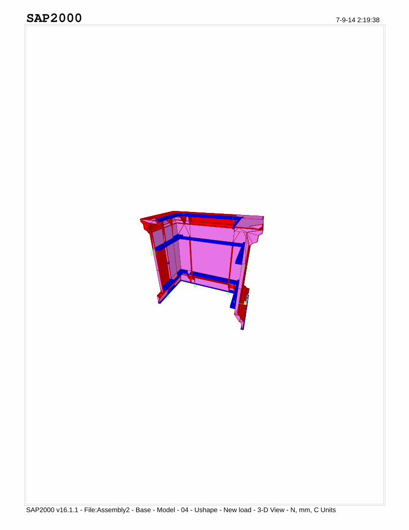
4.1. Column bases HC-SR-2.2:
This element is a corner column base (shown in figure 1) and it is directly rested on the ground slab while retrained from top by the steel frame.
The upper fixings are 10080505mm steel angles fixed with bolts to the steel sub frame.
This element is modeled in SAP 2000 Ver. 16 as finite element to check the stresses introduced due to wind and gravity loads and the outputs found as follows:
;Maximum Tension Stress in GRC shell elements; ftGRC = 4.690 N/mm2;
ftGRC<tGRC "Section
is Satisfactory";
;Maximum Compression Stress in GRC shell elements; fcsGRC = 5.956 N/mm2;
fcsGRC<cGRC "Section
is Satisfactory";
while the common thickness of the GRC elements is 12mm there are some elements thickened to 20mm (mainly the side trimmers). The stiffeners ribs at the back of the panel are modelled as 20mm thick stiffeners shells.
Figure 1

Project St. Rigs Hotel
Job Ref.
Water Wheel
Structure GRC Curtain walls
Part of Structure Podium
Sheet no./rev. 1 /a
Dubai Investment Park Tel: 04-3974618 Fax: 04-3974617
email: [email protected]
Calc. by
Date
18-Jul-14
Chck’d by F.G.
Date
18-Jul-14
App'd by
Date
Ref. Calculations Output
Design of GRC elements
This design report is prepared for the GRC elements of the elevations of St. Rigs Hotel – Dubai United Arab Emirates.
The design report is focused on the design of GRC elements and their fixing arrangements.
The design is based on the below mentioned design and loading criteria determined in accordance with BS standards.
1. GENERAL DESIGN CRITERIA:
Loading code:
ASCE7-10 for Wind Loads.
;Minimum Concrete Strength; fcu = 30.0 N/mm2;
;Allowable bearing stress on concrete; ball=0.4fcu=12.0N/mm2;
;GRC Modulus of Rupture; MOR = 18.0 N/mm2;
;GRC Limit of Proportionality; LOP = 6.0 N/mm2;
;Allowable tension stress in GRC elements; tGRC=min((MOR/3),LOP)=6.000N/mm2;
;GRC Compression Strength; fcGRC = 30.0 N/mm2;
;Allowable Compression stress in GRC elements; cGRC=0.33 fcGRC=9.900N/mm2;
;Yield Stress of Structural steel; fy = 275.0 N/mm2; (grade S275 for elements lesser than 40mm thick as per EN 10025-2)
2. GEOMETRY:
;GRC skin thickness; Sth = 12.0 mm;
SAP2000
SAP2000 v16.1.1 - File:Assembly2 - Base - Model - 04 - Ushape - New load - 3-D View - N, mm, C Units
7-9-14 2:19:38

SAP2000
SAP2000 v16.1.1 - File:Assembly2 - Base - Model - 04 - Ushape - New load - Stress S11 Diagram - Visible Face (Ultimate enve
7-9-14 2:16:30
-0.40 0.00 0.40 0.80 1.20 1.60 2.00 2.40 2.80 3.20 3.60 4.00 4.40 4.80

SAP2000
SAP2000 v16.1.1 - File:Assembly2 - Base - Model - 04 - Ushape - New load - Stress S22 Diagram - Visible Face (Ultimate enve
7-9-14 2:17:16
-1.60 -1.20 -0.80 -0.40 0.00 0.40 0.80 1.20 1.60 2.00 2.40 2.80 3.20 3.60

SAP2000
SAP2000 v16.1.1 - File:Assembly2 - Base - Model - 03 - Ushape - Joint Reactions (Service envelope) - KN, m, C Units
7-5-14 3:02:28

Project St. Rigs Hotel
Job Ref.
Water Wheel
Structure GRC Curtain walls
Part of Structure Podium
Sheet no./rev. 10 /a
Dubai Investment Park Tel: 04-3974618 Fax: 04-3974617
email: [email protected]
Calc. by
Date
18-Jul-14
Chck’d by F.G.
Date
18-Jul-14
App'd by
Date
Ref. Calculations Output
4.2. Cornice 7:
This element is composed of three parts (shown in figure 2).
The three parts are supporting each other and while resting on the secondary steel supports.
Each element is modeled in SAP 2000 finite element structural software to assess the stresses in the GRC elements and the reactions of the upper elements are applied as joint loads in the lower elements.
The elements are composed of vertical ribs of variable sections distributed at 500mm intervals at the back of the 12mm front shell.
The analysis outputs found as follows:
4.2.1. Upper Cornice part (HC-SR-7.1):
;Maximum Tension Stress in GRC shell elements; ftGRC = 4.841 N/mm2;
ftGRC<tGRC "Section
is Satisfactory";
;Maximum Compression Stress in GRC shell elements; fcsGRC = 5.287 N/mm2;
fcsGRC<cGRC "Section
is Satisfactory";
While the common thickness of the GRC elements is 12mm there are some elements thickened to 30mm and some are beyond that (mainly the side trimmers).
Figure 2

SA
P2
00
0
SA
P20
00 v
16.1
.1 -
File
:A2.
Cor
nice
-7.2
- 3
-D V
iew
- K
N, m
, C U
nits
7-17
-14
23:2
5:04
SA
P2
00
0
SA
P20
00 v
16.1
.1 -
File
:A2.
Cor
nice
-7.2
-
Str
ess
S11
Dia
gram
- V
isib
le F
ace
(U
ltim
ate
enve
lope
) -
N, m
m, C
Uni
ts
7-17
-14
23:2
7:39
-6.0
0-5
.40
-4.8
0-4
.20
-3.6
0-3
.00
-2.4
0-1
.80
-1.2
0-0
.60
0.00
0.60
1.20
1.80

SA
P2
00
0
SA
P20
00 v
16.1
.1 -
File
:A2.
Cor
nice
-7.2
-
Str
ess
S22
Dia
gram
- V
isib
le F
ace
(U
ltim
ate
enve
lope
) -
N, m
m, C
Uni
ts
7-17
-14
23:2
8:02
-7.2
0-6
.30
-5.4
0-4
.50
-3.6
0-2
.70
-1.8
0-0
.90
0.00
0.90
1.80
2.70
3.60
4.50

SA
P2
00
0
SA
P20
00 v
16.1
.1 -
File
:A2.
Cor
nice
-7.2
-
Join
t Rea
ctio
ns
(Ser
vice
env
elop
e) -
KN
, m, C
Uni
ts
7-17
-14
23:2
3:20

Project St. Rigs Hotel
Job Ref.
Water Wheel
Structure GRC Curtain walls
Part of Structure Podium
Sheet no./rev. 12 /a
Dubai Investment Park Tel: 04-3974618 Fax: 04-3974617
email: [email protected]
Calc. by
Date
18-Jul-14
Chck’d by F.G.
Date
18-Jul-14
App'd by
Date
Ref. Calculations Output
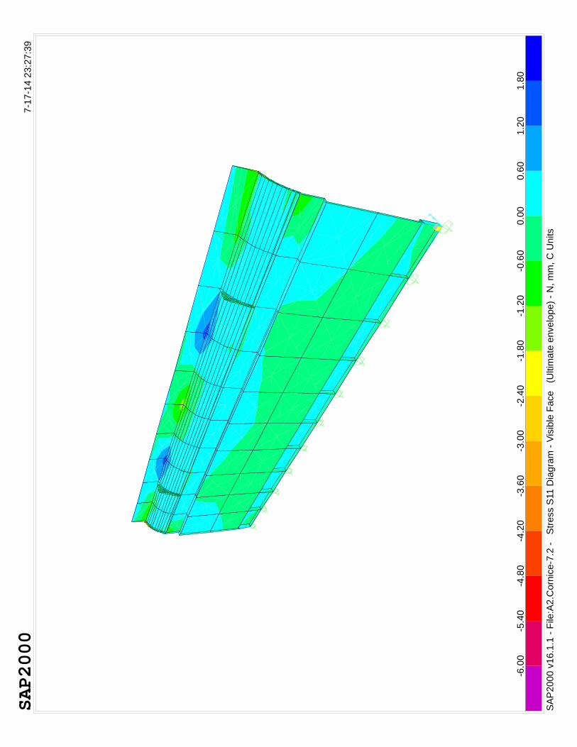
4.2.2. Middle Cornice part (HC-SR-7.2):
;Maximum Tension Stress in GRC shell elements; ftGRC = 4.668 N/mm2;
ftGRC<tGRC "Section
is Satisfactory";
;Maximum Compression Stress in GRC shell elements; fcsGRC = 8.085 N/mm2;
fcsGRC<cGRC "Section
is Satisfactory";
While the common thickness of the GRC elements is 12mm there are some elements thickened to 30mm and some are beyond that (mainly the side trimmers).
The maximum displacement of the structure is below 1mm for the envelope service case as shown in the table below:
A set of output charts are attached herewith together with the table outputs extracted from the software report.
TABLE: Joint Displacements
Case Type U1 U2 U3 R1 R2 R3
mm mm mm Radians Radians Radians
Max 0.558048 0.023903 0.061559 0.001106 0.00142 0.001685
Min -0.257159 -0.023739 -0.066536 -0.0010729 -0.001729 -0.001696
SA
P2
00
0
SA
P20
00 v
16.1
.1 -
File
:A2.
Cor
nice
-7.3
- 3
-D V
iew
- N
, mm
, C U
nits
7-17
-14
23:5
5:31

SA
P2
00
0
SA
P20
00 v
16.1
.1 -
File
:A2.
Cor
nice
-7.3
-
Str
ess
S22
Dia
gram
- V
isib
le F
ace
(U
ltim
ate
enve
lope
- M
ax)
- N
, mm
, C U
nits
7-18
-14
2:30
:21
-1.8
0-1
.20
-0.6
00.
000.
601.
201.
802.
403.
003.
604.
204.
805.
406.
00

SA
P2
00
0
SA
P20
00 v
16.1
.1 -
File
:A2.
Cor
nice
-7.3
-
Str
ess
S11
Dia
gram
- V
isib
le F
ace
(U
ltim
ate
enve
lope
- M
ax)
- N
, mm
, C U
nits
7-18
-14
2:29
:37
-1.0
0-0
.50
0.00
0.50
1.00
1.50
2.00
2.50
3.00
3.50
4.00
4.50
5.00
5.50
SA
P2
00
0
SA
P20
00 v
16.1
.1 -
File
:A2.
Cor
nice
-7.3
-
Join
t Rea
ctio
ns
(Ser
vice
env
elop
e) -
N, m
m, C
Uni
ts
7-18
-14
2:22
:43

Project St. Rigs Hotel
Job Ref.
Water Wheel
Structure GRC Curtain walls
Part of Structure Podium
Sheet no./rev. 14 /a
Dubai Investment Park Tel: 04-3974618 Fax: 04-3974617
email: [email protected]
Calc. by
Date
18-Jul-14
Chck’d by F.G.
Date
18-Jul-14
App'd by
Date
Ref. Calculations Output
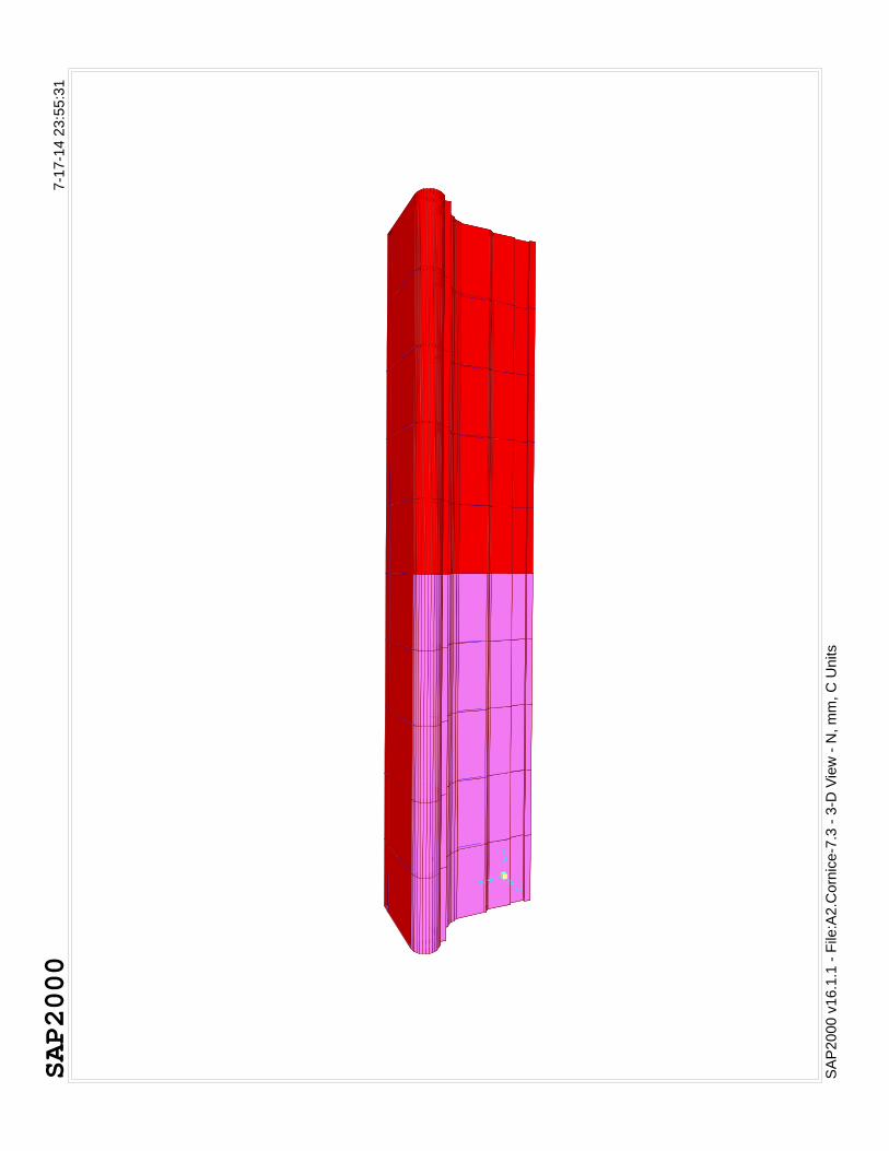
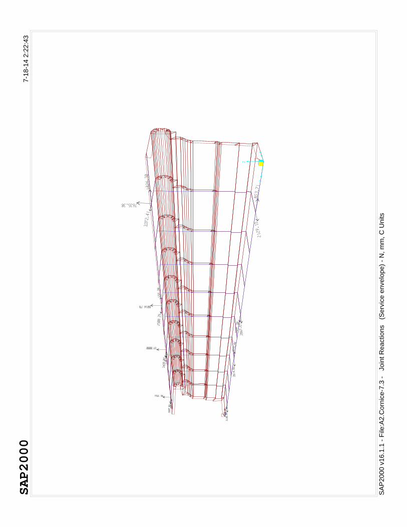
4.2.3. Bottom Cornice part (HC-SR-7.3):
;Maximum Tension Stress in GRC shell elements; ftGRC = 5.788 N/mm2;
ftGRC<tGRC "Section
is Satisfactory";
;Maximum Compression Stress in GRC shell elements; fcsGRC = 8.279 N/mm2;
fcsGRC<cGRC "Section
is Satisfactory";
While the common thickness of the GRC elements is 12mm there are some elements thickened to 50mm and some are beyond that (mainly the side trimmers).
The maximum displacement of the structure is below 1mm for the envelope service case as shown in the table below:
A set of output charts are attached herewith together with the table outputs extracted from the software report.
TABLE: Joint Displacements
Case Type U1 U2 U3 R1 R2 R3
mm mm mm Radians Radians Radians
Max 0.124826 0.390345 0.117544 0.445646 0.000322 1.524243
Min -0.070719 -0.0303 -1.023658 -0.235017 -0.002955 -3.579772

SAP2000
SAP2000 v16.1.1 - File:Column - 3-D View - KN, m, C Units
7-18-14 1:35:08

SAP2000
SAP2000 v16.1.1 - File:Column - Stress S11 Diagram - Visible Face (Ultimate envelope - Max) - N, mm, C Units
7-18-14 1:39:12
-1.00 -0.85 -0.69 -0.54 -0.38 -0.23 -0.08 0.08 0.23 0.38 0.54 0.69 0.85 1.00

SAP2000
SAP2000 v16.1.1 - File:Column - Stress S22 Diagram - Visible Face (Ultimate envelope - Max) - N, mm, C Units
7-18-14 1:41:11
-1.50 -1.31 -1.12 -0.92 -0.73 -0.54 -0.35 -0.15 0.04 0.23 0.42 0.62 0.81 1.00

SAP2000
SAP2000 v16.1.1 - File:Column - Joint Reactions (Service envelope) - KN, m, C Units
7-18-14 1:42:34