design of driven elements for vhf/uhf yagi antennasthe-eye.eu/public/books/electronic...
TRANSCRIPT

The design of Driven Elements for VHF/UHF Yagi Antennas
Modeling, observations and some case studies.
Graham Daubney, GBMBI
l . Introduction What I present here is intended to provoke thought and experimentation. Whilst I do present some practical solutions. to both the modeling and real world of antennas. my intent is to make input to those who have an interest in both designing and building their own antenna systems, share some views and opinions, and perhaps prompt some of those with deeper understanding and/or more sophisticated testing facilities, to contribute in future. What I do not intend is to infer that a huge problem exists, but simply to explore and try to move forward the constant improvement process
Antenna modeling is now a large part of many peoples interest. it can also however be a 'lone' part of the hobby, 1t 1s possible that many people have seen similar results to these and are also wondering. I want to encourage some data/experiences exchange. If you have input or constructive criticism they are welcome at my email address.
I am truly a radio amateur and not a professionally trained engineer or mathematician I am a kind of 'hands on guy' who likes to play with, and practically use. both modeling soft-
DUBUS 4/1 998 20
ware and physical realisations of antennas in my Hobby. My discussion covers a number of areas and poses some questions as well as offering some solutions
1. EinfUhrung Mit diesem Artikel mcichte 1ch die1enigen. die Antennen selbst bauen oder konstruieren, mit einigen Erfahrungen, ldeen und Gedanken versehen, welche die Speisung von Yagis betreffen.
Die Modellierung und Simulation von Antennen ist inzwischen gut verbreitet. Auch Amateure haben Zugnff zu der entsprechenden Software. Als echter Amateur - lch bin kein lngenieur - mochte 1ch e1nige Erfahrungen und Erkenntnisse m1tteilen
2. Why Focus on the DE? The DE can be viewed alternately as both the least important part of a Yagi antenna and yet the most important part of a high perfonnance system.
It's purpose is purely that of coupling your transmitter into the antenna, no more and no less. In purely theoretical tenns it has little or no effect on the pattern, gain or other parame-

Graham Daubney. G8MBI: Driven Elements for VHF/UHF Yogis
ters of the antenna. Yet, in practical terms it. can have major effect on the antennas performance. Especially in the area of realised gain and pattern. A good antenna design can be very quickly turned into a mediocre or even poor design by accumulated losses within the DE, especially those coming from any matching system and the cable attached to it, which frequently and unintentionally gets employed as a matching device. This must be viewed very seriously when trying to operate 'on the edge'. As a practical example let me take a recent realworld case.
A 144mhz EME system was being constructed, the antenna chosen was a group of four 5 lambda boom yagis. The particular antenna chosen was picked because it had a rather good gain performance and a group of 4 produced a lheoretical gain of close to 21 dbd. Most people spend a lot of time, effort and finally money, to select what they consider to be the very best and will spend hours or weeks consulting papers and other people for opinions and facts, often choosing a difference of 0.2 db just to have the 'best'.
What happened here was that on checking the DE assembly it became clear lhat there were 0.2db losses in the balun and connections associated with the balun and cable connections. Plus a further 0.2db losses because the balun was in fact not of correct length. Some further potential for additional cable losses because of poorish return loss. The presence of the balun within the yagi was not considered, but one can safely assume that there wi ll be additional degradation because of that also.
What this means is that the overall system performance was only equivalent to a group of 4.5 lambda antennas with DE's that are running more efficiently, in fact when reduced feeder lengths are considered, then the 4.S's are even better. The group of 5 lambda antennas had, In effect, a total of over 4 metres of boom doing nothing. More importantly the 4.5 lambdas would have reduced stacking distance requirements and would also save a total of 2 metres of stacking frame. The wind loading savings and weight savings are also significant. Why spend weeks choosing or,
21
worse still designing and building an array to have this happen. ? The moral 1s that in designing or choosing high performance antennas then pay attention to details OTHER than quoted gain numbers.
To design a good yagi is not enough, you also have to get the antenna coupled properly and efficiently into the rest of the system AND you have to be able to actually build a DE in a reliable manner with respect to finding parts to fabricate it with and, for most people, with simple hand tools.
2. Bedeutung des Speiseelementes Man kann das Speiseelement als den unbedeutendsten aber auch als den wichtigsten Teil einer YAGI betrachten.
Seine Bedeutung liegt darin, die Leistung aus dem Speisekabel in die Antenne zu koppeln. Rein theoretisch hat dieses Element wenig EinfluB auf die Parameter Diagramm und Gewinn. Praktisch ist jedoch oft der EinfluB nicht zu vernachlassigen.
Ein gutes Design kann schnell mittelmiiBig werden, wenn sich Verluste im Speiseelement oder Anpassungsgliedern summieren.
Als Beispiel sei ein System von 4 Yagis genannt, die jeweils SA lang sind und einen Gewinn von ca. 21dBd produzieren. Viele Leute wahlen eine Antenne aufgrund von Gewinnunterschieden von 0,2dB aus. Der Besitzer der Antennen entdeckte nach einiger zeit, daB die Lei stung der Antenne nicht wie erwartet war. Es fehlten ca. 0,5dB, die durch Balun m it falscher Lange ur.d einen schlecht konstruierten Faltdipol entstanden waren.
Das bedeutete, dal3 der Gewinn dieser Gruppe dem Gewinn von verlustlreien Antennen mil 4,5A Lange entsprach. D.h. 4x1 m=4m Boomlange waren iiberfliissig. Zudem hatte man die Antennen von 4,5A dichter stocken konnen, ganz zu schweigen von der Windlast. Mil anderen Worten, warum sollte man nicht alle Eigenschaften optimieren, wenn man schon eine Menge Zeit, Geld und Arbeit in eine Antenne investier\?
DUBUS 4/lQQA

Graham Daubney. G8MBI: Driven Elements for VHF/UHF Yogis
Eine Antenne zu designen ist nicht genug. Man mull sich Gedanken Ober geeignete Speisesysteme machen, die optimal sind im elektrischen Sinne, der Mechanik und der Reprozierbarkeit mil einfachen Werkzeugen.
3. Return Loss and SWR. There is a good deal of focus in the following on return loss and SWR. That should not be misunderstood, it is worth remembering that SWR is only an indicator.
Having a poor SWR does not necessarily indicate that an antenna 1s bad, but it might give problems and loss opportunities in other system components.
Equally having a very good and rather flat 'in shack' SWR is not a very good sign either. When one sees this situation it is often time to start looking for losses in the system. In fact the above example is a very good case where the losses in both balun system and construction actually improve SWR whilst significantly reducing systems elflc1ency.
Good or bad return loss 1s not necessarily an indicator of goodness or badness of an antenna or systems efficiency. In most practical systems a return loss of better than 25db AT the antenna is rather hard to realise except in perhaps one very narrow band spot, equally 16 to 20 db can probably be considered as good enough, at 144 anyway.
The make up of the match is rather more critical, a good match in narrow bandwidth or with a specific feeder length maybe OK 1f you know that this is what you have. but if you do not know it, it may lead to a nasty surprise just when you think you have finished building the system.
3. VSWR der Antenne Das VSWR einer Antenna isl nur ein lndikator.
Hat man eln schlechtes VSWR, heif3t das nicht, das die Antenne schlecht ist. Es konnte allerdlngs zu hoheren Verlusten Anlal3 geben.
DUBUS 4/1998 22
Ebenso ist ein gutes VSWR kein hinre1chendes Zeichen fUr einen gute Antenne Ein gu· tes VSWR hat z.B. eine 'Dummyload' D.h gute Anpassung kann auch von inneren Verlusten herruhren, die den W1rkungsgrad vermindem.
Daher isl eine Ruckflul3dampfung von mehr als 20dB (VSWA=1 ,22) fUr den SSB-Bereich des Bandes gut genug
4. DE in software models Optimisation of antennas using computer modeling has progressed a long way in the last 10 years. Over a period of four years I have attempted to play with and understand some of the many software packages now available. I always had the same problem, I could design very nice yagis with apparently good parameters but "what to do about modeling the DE" ? and, even more importantly, "can i really model the matching system" ? and why do my models not correlate well with the real world.
The solution adopted by VE7BQH during his comparison work (1 .) was to 'normalise' all the antennas by making no attempt to model the respective DE's and their matching systems but to insert a straight split dipole into each model and tweak the length appropriately to reduce any reactance so as not to influence the gain figure unduly Whilst 11 can be argued that this process does not truly represent the real world antenna, 1t 1s the ONLY current sensible way to make antenna comparisons in modeling.
For the rest of the antenna we have a lot of modeled to real world correlation effort that has provided what appear to be reliable corrections for boom diameters and mounting methods and element length corrections for material size changes or tapering. One can therefore design in software and simply build the antenna with confidence. But we have little in the area of modeling to reality correlation in the area of Driven Elements.

Graham Daubney. GSMBI: Driven Elements for VHF/UHF Yogis
4. Speiselemente als Software-Modelle In den letzten 10 Jahren sind einige Softwa· repakete verfOgbar geworden, mit denen man Antennen simulieren kann. tch selbst spiele seit 4 Jahren damit rum. Dabei hatle ich irnrner das Problem, wie man Speiseele· mente und Anpassungsglieder modellieren kann.
VE7BQH (1) hat in seiner Arbeit alle Antennen rnit einern geraden Dipol simuliert, unabhan· gig wie nun bei der jeweiligen Antenne das Speiseelement wirklich aussah.
Bei den Direktoren und Reflektoren gibt es genug experirnentelles Wissen und daraus abgeleitete Forrneln, urn unterschiedliche Belestigungsrnethoden, Boorndurchrnesser oder Elernentdicken zu berucksichtigen. Das erlaubt praktisch den Bau einer funktionierenden Antenne direkt abgeleitet aus den Ergebnissen der Simulation.
Fur das Speiseelernent existieren solche Erfahrungen meines Wissens nicht.
5. Where a re the software issues in modeling DE ? It seems that modeling software has a num· ber of issues in this area, centred round the ability to model properly the junctions of dissimilar wire sizes and end effects that are not well understood, even in the real world, contributing to a "fuzzy' comparison between modeling and real world results.
I made many atlempts to correlate the performance of well known DE systems (lor example f9ft hairpin) by modeling, using the supplied DE matching options in YO (2.) The results did not seem to be quite as expected. I have recently been told that in fact on HF the results given by YO are quite close. I suspect (but do not know) that results here are being affected by additional capacitance and inductance that even short connections and proximity have on vhf/uhf. (?) Perhaps the matching menu items have been calibrated against realworld HF results.
23
In any event the majority of these options utilise components In the matching process, these imply either difficult to find components or difficult fabrication lor high power use and, at VHF and above, are unnecessarily lossy. YO is a super program for a quick evaluation or very quickly knocking a new antenna broadly into shape. I strongly recommend however that DE's only be modeled as straight split (and resonant) dipoles, where results appear to be at least in the ballpark.
I quickly moved from YO to AO (3.) , which being a full wires based modeler in x,y,z geometry allows a potentially more accurate model to be constructed. It also claims to handle junctions of dissimilar wire diameters. Once again atlempts to model well known real world and well used designs gave some strange results. I conclude that modeling anything that uses junctions of dissimilar wire diameters as part of the matching process should not be atlempted.
Probably the most popular design for a DE on 144 and 432 is the folded dipole it is a 'logical' choice arid clearly the work of DL6WU and later DJ9BV have had large influence here. It also appeared that this should in fact be modeled more accurately than many others such as hairpin, 't' match or gamma match, because those generally involve, necessarily so to work, dissimilar diameter junctions, whereas a fol~ed can be modeled in uniform diameters.
The folded, by having common material size throughout , was also able to be run in NEC for Wires 2.05 [4.] as well as AO. Although not the main theme of this article, I should also note that tables and models presented here have been run at 20 segments in Nee for Wires 2.05, it can be argued that higher segmentation density is necessary (or even perhaps less), but the choice of 20 was arrived at as a reasonable compromise between accuracy and processing time, from extensive prior study (by myself and others) it also appears well into the flattening part or the curve that can be plotted of accuracy/change versus segmentation density.(5.) Polar plots were run quickly in AO at 1 O segments.
f)lJRlJS 411998
L.
Graham Daubney, G8MBI: Driven Elements for VHF/UHF Yogis
Modeling of folded dipoles in software has proven to be an extremely thorny issue. Most of the sets of antennas available from real world designs that target 50 ohms intrinsic (in order to be fed by a folded with 4:1 impedance transformation and then 4:1 balun back to 50 ohm feeder) seem to display very poor mod· eling results, often with rapidly swinging R component and high J values. Thus making an apparently highly reactive match and somewhat surprisingly, given that prior wis· dom was that foldeds gave a better bandwidth than straight dipoles, often displaying a very narrow match.
When compared with results from a number of stations actually building/using these designs, it was clear that the modeling software was showing the correct trend, but the real world results, whilst displaying reactance and some overall mismatch were not as extreme as models predicted. They were/are however still apparently wrong. A number of people have also thought up a variety of cunning 'cheats' to correct this after the event, such as benVre-positioned 01 's, re-drilled DE position holes and carefully chosen cable lengths to feed them with. On most, simply 'fiddling ' with 01 does not fix it completely.
Great effort was expended by a number of keen amateur modelers in an attempt to construct new antennas in software that utilised folded dipoles, myself included, working mostly in AO and then comparison/verification in Nee for wires 2.05. I could almost never arrive at a satisfactory solution to get from 50ohms to 200ohms, I could however make solutions that looked OK from lower starting values (such as 16 transformed to 75), these lower starting value solutions clearly also worked in the real world, and on later generation antennas, as SM2CEW had used this technique in his very successful array. My results here using this method on 432 also indicate success, but only after some linear length correction of the folded dipole.
The reason was still unclear. but appeared to be that there was a major issue in most modeling packages available. More or less I concluded not to use folded dipoles in mod-
DUBUS 4/1998 24
els. (or real world if possible, but more on that later)
In 1997 some new software became available called NEC WIN PRO. Lionel VE78QH then re-visited this subject and has perhaps shone some new light on the area. The arrival of this software prompted Lionel to do further work and resulted in the model of a folded dipole with apparent good results in a NEW design. The complex impedance behaved very nicely with good bandwidth and the antenna itself was rather competitive in gain and g/t terms.
This antenna when run in both AO and NEC for wires 2.05, with a folded dipole modeled, now also shows much more expected and acceptable results, with close correlation to those achieved with a straight split modeled, so maybe the issue was/is not all in software?
What has been done here is two things, firstly the linear length of the dipole has been adjusted carefully, the actual overall dimensions with respect to length versus depth are not that critical (this was already well known from long ago and recent modeling, at least within sensible ratios) but more critically this antenna has a much broader 50 ohm bandwidth, than those previously examined. The match is much closer to 50 ohms non reactive.
This work appears to have pointed in another direction, namely that to get a folded to work well in either modeling or real world it is necessary to have a more stable and much closer to 50 ohms impedance within the ANTENNA itself than many currently available designs show. This antenna has been built using a straight split dipole and showed good real world to model correlation like that, what has not yet been Jested is a folded dipole.
It is also necessary in the real world to fabricate both the folded itself and the Balun VERY carefully, as pointed out in prior construction notes that have accompanied these type of designs. Length of tails on the balun and low inductance paths are essential.
My current conclusion is that earlier work with folded dipoles utilised them in relatively 'tame· designs wilh respect to bandwidth, based mostly on the work of DL6WU. Whilst these
Graham Daubney. GSMBI: Driven Elements for VHF/UHF Yogis
have not necessarily presented an excellent return loss, they have shown a relatively flat return loss. It seems that the majority of people are also only checking return loss or SWR 'in shack' and not necessarily close enough to the antenna. So big attention has not been drawn to the issue.
As more and more software has become available and an increased number of people have been able to create new designs then the 'race· to find highly optimised designs is well and truly on. That has highlighted the return loss Issue as it is no longer flat in large bandwidths but displays a reasonably rapid rate of change. It has become much more difficult to get an acceptable part of the curve (high return loss part) to match where you want to operate when realising a real world design from computer constructed models. THAT is the issue, not necessarily one of bad or poor designs but how to get good correlation from models to real world.
In fact the process of "optimisation" in yagi antennas is not really that at all, it is perhaps more correctly described as a process of "compromisation". No matter how good the software or the skill and knowledge of the operator (designer) then you can never get something for nothing. The pressure to constantly strive for better gain and better Grr in high performance yagis introduces the need to compromise in some other area, the easiest compromise to accept is Bandwidth. At least on your computer screen I This may be responsible for highlighting the issue but most likely not It's fundamental cause.
Although one possibly cannot trust entirely the software outputs that Nee for Wires 2.05 and NEC WIN PRO arrive at, they do appear to at least show a general trend. They also show some trend of this issue as each generation of antennas is arriving.
The earlier DL6WU 10 element, first generation, and BV 4 Lambda. second generation, show at least partial correlation between the folded and straights models with the transformation being close to 4:1 although the modeled resulting swr is not that wonderful it is relatively flat. By the time the third generation
25
of BV0-4wl arrives then a faster swinging J component is arriving. Coming completely upto date we arrive at the fourth generation with BV0-3wl, by now we have a very broadly swinging J component. Please remember I am not claiming these modeling numbers are exactly correct, but only that they show the (inevitable?) trend. Modeling results of some of these popular antennas are shown in table 1.
BEFORE you go and look at that I would like to clearly state that it is not my intention to imply or state that DL6WU or DJ9BV antennas are bad, have a major issue, or should all be taken down and thrown away immediately. It is indeed a compliment that the majority of antennas available to study, both in real world and modeling, emanate from the work of these people, both have been prolific in output and responsible for a continuous improvement in, and understanding of, Yagis. It is however an ongoing and emerging fact that there are some issues arising here which we should all address in order to continue the improvement process. With the recent release of the new BVO series [6.] Rainer has once again produced competitive designs that are excellent performers In Gain and Grr. However the issue of how to centre the usable match portion of the antenna/DE to the frequency you want to use it on, remains.
You must also be careful exactly what you model and how. The foldeds modeled in this table have been software constructed with "flat ends' and the linear lengths have therefore been corrected to compensate. I have attempted to model more accurately constructed foldeds with curved ends, the effort needed to do that in x,y,z geometry is high and results show little deviation from those obtained here. Which indeed may be indicative of part of both the modeling and correlation to real world issues.
5. Grenzen der Modellierung Es scheint nicht einfach zu sein, in den Oblichen Programmen genaue Simulationen von Speiseelementen zu erhalten.
DUBUS 411998

Graham Daubney, G8MBI: Driven Elements for VHF/UHF Yogis
Table 1: Impedances of Yagls
Generation l 12 13 4 13-4
Antenna DL6WU-10 1sv-4wl BV0-4wl BV0-3wl BQH-12j
Physical Fol-ded: Over-
990 by66 -, 990 by66 990by66 990by66 -
all I Dimensions
Modelled 958 by 58 958 by 58 958 by 58 958 by 58 948by66 as (1), Cen-tre to Centre - .__ 144.000 Imo 192+64 173+37 189+41 209+82 199-2
swr l.39 l.28 1.24 1.50 l.01
144.500 Imp 227+61 200+47 209+26 304+16 198-6 - -swr l.37 1.27 1.15 J..:_53 1.03 - 1
195-6 145.000imo 261+23 ~+31 213-6 202-161 -i
f i.04 swr l.34 1.25 11.07 - 2.19 - -Straight Split 990 990 980 968 990 dipole of
~ lenath - ,__ 144.000 imp 45.6+8 42.6+5.9 44.4-0.7 46.8-0.2 51.1+0.3
~
swr 1.22 l.23 1.13 1.07 1.02
144.500 Imp 54+0.9 49.3+9.5 49.3-2.7 68.9-12.9 51.0+0.4 - .__ -swr l .21 1.21 1.06 1.47 1.02
I 145.000 imp 62.6+2 58.7+7 50.8-9.4 48.0-54.2 50.5+ l.1 -r--swr l.24 1.23 1.21 2.88 1.02
notes: 1. Modelled with square ends and so linear length corrected. 2. At 20 segments in Nee for Wires 2.05
lch habe einige Versuche unternommen, die Eigenschaften von bekannten Speiseanordnungen zu bestimmen. Z.B. habe ich versucht, die 'hairpin' Anpassung von F9FT zu modellieren. Wahrend die Ergebnisse mit VO [2] auf HF brauchbarwaren, waren sie auf VHF unbrauchbar.
DUBUS 4/1998 26
lch ging dann zu AO (3] Ober. Da es ein segmentiertes Verfahren ist und der Hersteller sagt, daf3 Teile mil verschiedenen Durchmesser verbunden werden konnen, war ich guter Hoffnung auf brauchbare Resultate. Die Unterschiede zwischen Simulation und Praxis waren jedoch wieder ziemlich drastisch.

Graham Daubney, G8MBI: Driven Elements for VHF/UHF Yogis
Sehr beliebt als Speiseelement auf 144 und 432MHz isl der Faltdipol nicht zuletzt beeinflul3t durch die Arbeiten von DL6WU und DJ9BV, die diese Konstruktion empfehlen. Er scheint auch einfacher zu modellieren zu sein, als 'hairpin', 'T-match' oder "GammaMatch', die verschiedene Durchmesser im Medell erfordern. Der Faltdipol kann dagegen ohne Durchmessersprunge modelliert werden.
Faltdipole wurden sowohl in NEC/Wires 2.05 (4) als auch in AO simuliert. Dabei werden in NEC 20 Segmente verwendet. Dies scheint nach den Erfahrun.~en von SM5BSZ (5) ausreichend zu sein. Uberraschenderweise entpuppte sich die Aufgabe, Yagis mit Faltdipol zu simulieren als ausgesprochen dornige Aufgabe. Yagis mil 500hm Eingangsimpedanz, die Ober einen Faltdipol und einen 4:1 Balun wieder auf 500hm angepal3t werden, zeigten in der Simulation oft schlechtes VSWR und/oder Anpassungsbandbreite. Das wird auch von einer Reihe Stationen, die solche Anordnungen gebaut haben, berichtet. Allerdings waren die realen Messungen nicht so schlecht wie die Simulationsresultate.
Viele, auch ich. haben versucht, Antenne mil 500hm lmpedanz zu entwerfen und sie Ober Faltdipole zu speisen. Sowohl in der Simulation als auch in der Messung brachten die meisten Entwurfe nicht die gewunschten Anpassungsresultate, obwohl alle Simulationen in NEC/Wires ausge!Ohrt wurden.
Im Jahre 1997 wurde die Software NEC WIN PRO ver!Ogbar. VE7BQH entwarl eine neue Antenne, die selbst schon eine grol3e Anpassungsbandbreite zeigte. Auch eine Simulation mil Faltdipol zeigte ein sehr gutmutiges Verhalten, nachdem die Lange sorgfaltig justiert worden war. Es scheint, dal3 eine Voraussetzung fur gute Anpassung mil Faltdipolen ein 'gutmOtiges' Design der Yacht, oder anders gesagl eine gute Anpassungsbandbreite der Antenne isl.
Mil 'giftigeren' Antennen, die eine kleine Anpassungsbandbreite mil sehr schnell veranderlichem lmaginarteil der lmpedanz haben, isl die Anpassung Ober einen Faltdipol we-
27
sentlich schwieriger. Die Konstruklion mul3 jedenfalls sehr sorgfaltig mil geringst moglichen parasitaren lnduktivitaten und Kapazitaten erfolgen.
Meine gegenwartige Schlu13folgerung isl, dal3 speziell bei den Antennen von DL6WU relativ gute Anpassungsbandbreiten die Regel waren und deswegen die Mehrheit der Nachbauer keine Probleme mil Faltdipolen hatte. Der VSWR-Verlauf war meistens rechl flach und aul3erdem messen die meisten Amateure im Shak, d.h. durch die Kabeldampfung geschonte Mel3werte fur das VSWR.
Heutzutage, wo Simulationssoftware jedermann zur VerfOgung steht, entstehen bei der Jagd nach dem letzten Zehntel dB an Gewinn leicht relativ kritische Konstruktionen, die sich nicht einfach Ober eine befriedigende Bandbreite anpassen lassen. Ebenso wird die Korrelation zwischen Modell/Simulation und realer Welt immer schlechter, weil die Simulationssoftware an die Grenzen der Genauigkeit geht.
Man kann Soltware wie NEC for Wires 2.05 bzw. NEC WIN PRO nicht vollstandig vertrauen. Sie zeigt aber zumeist wenigstens den Trend
Bei der Untersuchung von einer DL6WU 10 und einer BV 4.1.. zeigte eine Simulation den erwartet flachen Verlauf des VSWRs, wenn auch nicht ein sehr gutes Optimum der Anpassung. Neuere Designs wie die BV0-4wl (3. Generation) oder die BV0-3wl (4. Generation) haben, wie Tabelle 1 zeigt eine sehr stark veranderliche Eingangsimpedanz, somit eine kleine Anpassungsbandbreite. Die Zahlen aus der Simulation mussen nicht unbedingl absolut richtig sein, zeigen aber den beobachteten Trend.
Das Problem ist nach wie vor, wie man diese Antennen, die sehr gute Werle im Gewinn oder dem Grr haben, auf den gewunschten Frequenzbereich anpal3t.
Simuliert man Faltdipole, modelliert man solche mit flachen Enden, weil sie einfacher zu segmentieren sind. In der Praxis benutzt man aber meistens welche mil halbrunden Enden.
DUBUS 411998

,--·-- --Graham Daubney. G8MBI: Driven Elements for VHF/UHF Yogis
Table 2: Gain Drop
Gain drop due to DE misalignment In a yogi (gain figures In Dbd)
Band 144 144 432
Antenna BVO-Swl BV0-3wl BV070· 13wl
offset in mm
0 15.01 13.43 18.78
-10 15.01 13.43 18.76
-20 15.00 13.42 18.71
-25 15.00 13.42 18.66
-30 14.99 13.41 18.61 --35 14.99 13.41 18.53
-40 14.98 13.40 18.44
-50 14.96 13.39 too much
notes: 1. Modelled with square ends and so linear length corrected. 2. At 20 segments in Nee for Wires 2.05
Das ergibt schon Unterschiede in den Zahlen, wenn man nicht in der Gesamtlange korri· giert.
6. Foldeds in the real world My first reaction to the modeling results was "ok, but it cannot really be true". Many people have made antennas with folded dipoles and nobody seemed to raise this issue, there are perhaps thousands of people out there using them.
My real world testing ability on this issue is somewhat limited. I have extremely infre· quent and short term access to a network analyser. On a regular basis I can only perform rather simple return loss tests and check for reactance by insertion of random lengths of coax.
local tests indicated that It was in fact true that a folded was frequently pretty reactive and correlation from 'on screen' dimensions to real world dimensions is poor. Although not quantified, it appears that the result is not as
DUBUS 4/1998 28
extreme as models may indicate, but never· theless it does exist.
During this time I got involved with quite a number of European EME operators looking at many aspects of their antenna system design in models. Not entirely surprisingly to me I started to receive realworld return loss data from some of these guys that indicated both reactance and a funny resonance within folded dipoles, on several different antennas.
There also seems to be a consistent factor of best return loss being low in frequency. Implying that the most popular folded designs may be on the long side.
I am also of the opinion that having the balun within the antenna is having some confusing effect on correlation attempts. Although difficult to model, my attempts at modeling pieces of cable in close proximity to the other antenna parts does Indicate some serious interference potential in this area.

-- .L-
Graham Daubney, G8MBI: Driven Elements for VHF/UHF Yogis
This is now a very confused and difficult area to explore accurately, it appears that one can summarise the issues into 5 areas.
1. Perhaps poor modeling within software, not yet proven either way
2. Existence of significant and unquantified 'end' and other effects in the realisation of a folded dipole.
3. Effects of balun construction.
4. Effect of the physical presence of the balun within close proximity to critical and sensitive parts of the antenna.
5. More highly 'optimised' (effectively bandwidth compromised) designs highlighting items 1 to 4.
6. Faltdipole unter realen Bedingungen Ats ich die ersten Ergebnisse sah, dachte ich: 'Das kann nicht wahr sein!'. lrnrnerhin gibt es tausende von Amateuren. die funktionierende Yagis mil Faltdipolen benutzen. Meine Mel3rnittel sind bis auf den sehr seltenen Zugriff au! einen Netzwerkanalysator eher bescheiden: lch kann Verluste und VSWR rnessen.
lch konnte wohl bestatigen, dal3 Faltdipole in kritischen Antennen ziernliche Reaktanzen aufwiesen, obwohl nicht so schlirnrn, wie die Modellrechnung erwarten liel3.
Durch Gesprache mil europaischen EMEAmateuren land ich heraus, dal3 vie le andere diese Phanomene auch beobachtet hatten.
Bei Faltdipolen als Speiseelernent scheinen rnir folgende Probleme vorzuliegen :
1. Schwierigkeit, diese vernunftig zu simulieren
2. Vorhandensein von unbekannten parisitaren Effekten
3. Vorhandensein eines Baluns, dessen Nachbarschafl zu Elementen das Feld start
4. Designs mil kleiner Bandbreite verstarken die obigen Effekte
29
7. What to do ? .... Modeling For ALL forms of matches such as T', Gamma, Hairpin etc. then results are unreliable due to dissimilar wires junctions issues and may also be distorted further by the anomalies seen in foldeds.
For Foldeds results to date, it seems that results point the right trend, but again are not really close enough to model something and then build it with any great confidence.
For straight split dipoles the results from the better modeling packages look ok and when compared with realworld results seem rather close.
Given that a straight split dipole also has the easiest construction method, the least loss and the simplest form of adjustment (just cut it or slide it) then I recommend to use straight split simple dipoles in all modeling.
II you adopt that as a modeling philosophy then it also seems logical to adopt it in the real world, if possible.
7. Modellierung Exotische Formen wie T', Gamma oder Hairpin konnen nicht vernOnftig simuliert werden und man Isl auf Probieren angewiesen.
Die Resultate fur Faltdipole liegen abseils der gemessenen Realitat, so dal3 man auch auf Probieren angewiesen isl.
Bel einfachen gestreckten Dipolen liegen Simulation und Messung genOgend beieinander. lch bevorzuge sie deshalb als einfachste Speisemethode (Abb. 5).
8. Things to watch for in modeling .. Over time I have developed a list in my head of indications that may point to trouble corning with bandwidth reduction and highly gain optimised antennas. There are a number of characteristics/trends that highly gain pushed designs display, if you start to see these then it is time to look closely at your likelihood of getting a broad and reliable modeling to real world match. None of these mean the an-
DUFllJS 4/lQQR

Graham Daubney, GSMBI: Driven Elements for VHF/UHF Yogis
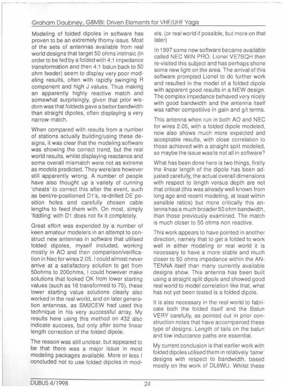
BUO-SUL YAG I Willi 4.76 MM DIAMETER ELE11BITS
DE i n Alignment
100· ..... ..... .
-1so·
0 d8 = 14.97 dBd
•, ·.
120· .. ··.
.. . . . : .... ... .
• • i
.·.
: . .. . .. : ..... .
··.
-120· ·· ..
60·
• ....
-io
.·
.·
-60·
dB
Free Space Eleuat lon
30·
o·
-Jo·
144 .300 MHz
Bild/ Figure 1: BVO-SWL with DE in Alignment
tenna is necessarily a bad or poor design, just that you may be getting close to the edge and that you are going to have to pay closer attention to matching, element corrections and construction accuracies. You may also start to see match changes in poor weather.
a) The gain peak of the antenna moves down, most often the gain peak will be slightly higher than the centre design/match frequency, if you start to see convergence of the gain peak and the centre design frequency then look out. I have personally deliberately exploited this in a number of my own, as yet unpublished, designs as this enables a very competitive git number to be generated.
b) The Front Rear of the antenna starts to degrade VERY rapidly on the high side of the design frequency and generally will consist of one large tail, rather than a number of lobes with nulls between.
DUBUS 4/1998 30
c) The impedance and reactance (and most often =return loss or SWR) swings rapidly on one side of the design frequency, the high side, but maintains at least some reasonable bandwidth on the other.
d) To create a combination of reasonable match and get back some of the Front Rear ratio you have to allow the last director to "go where it wants" during optimisation, this frequently leads to the last director being longer than the prior one and often longer than several prior ones. This in particular is very indicative.
e) In order to maintain any match at all, the length of the driven element, even a straight simple split dipole, starts to deviate from what one would normally cal l a common length, mostly significantly shorter. As a general rule of thumb if you start to see DE's outside the range of 980mm to 990mm on 144mhz, this is why.

- - · - - - - - - - - -- -- -- --·- --
Graham Daubney, G8MBI: Driven Elements for VHF/UHF Yo gis
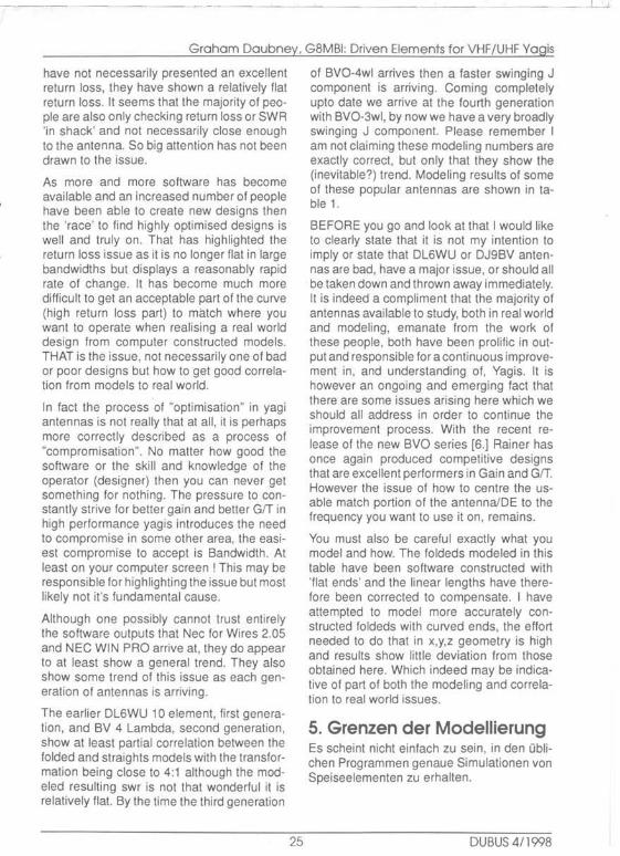
dubbuS YAGI Willi 4.76 MM DIAMETER ELEMENTS OE at -40mm offset
180°
0 dB = 14 . 91 dBd
· ..
.·
-60°
f r ee Space Elevation
141 .300 MHz
Bild/ Figure 2: BVO-Swl with DE 40mm Offset
Some of these will show up in designs that are not being pushed, but a combination of perhaps two or more of these is a sure sign.
As good examples, the BV0-3wl shows ALL of these symptoms as do the SMSBSZ designs I have looked at. That is because they are very competitive designs, one could even say .. leading published" designs.
8. Was man bei der Modellierung beachten muB Wenn man Antennen auf Gewinn zuchtet, gibt es einige Elfekte, die man beachten soll· le: 1. Die Frequenz mil dem maximalen Ge·
winn rutscht nach unten. Fallt sie mil der Mittenfrequenz des Arbeitsbereiches zusammen, kann man ein ordentliches GfT erwarten.
2. Das Vor-/ROckverhaltnis fallt oberhalb der optimalen Frequenz rapide ab.
31
3. Das VSWR wird oberhalb der optimalen Frequenz drastisch schlechter.
4. Der letzte Direktor isl oil !anger als die Vorganger, um optimale Anpassung und Vor-/ROckverhaltnis zu erzielen.
5. Um Anpassung zu erzielen wird das Speiseelement oft deutlich kurzer als Oblich, d.h. kurzer als 980mm.
Diese Symptome sind sowohl beim BVG-3wl als auch beim SMSBSZ Design zu linden, die zur Oberklasse im Gewinn gehOren.
9. What to do ? .. .. Real World I make no claim for originality here, only offer an opinion and strategy that works.
Apart from the difficulties of modeling, all forms of DE matching employing additional tubes, movable parts, or components, have either difficult to fabricate parts and/or potential for loss.
DU BUS c1/ l QOA
'

----- -----
Graham Daubney. G8MBI: Driven Elements for VHF/UHF Yogis
dj9bu opt70 13wl
OE i n alignment
150• .
100·
-1so· ·
0 dB = 18.73 cl8d
...
'•,
.. ···
120· .
... ..
: .
···.
. .. ·. ,•' . ·-.· . . : ...
· .. .
·.
- 120· ...
60"
- 10 dB
....
- 60"
free Space Eleuat ion
o·
-3o·
432.000 MHz
Bild/ Figure 3: OPT70_ 13wl with DE In Alignment
The traditional and well accepted folded driven has both advantages and disadvantages. It is undoubtedly the best theoretical choice, it offers, with the 4:1 balun, a good transition from balanced to unbalanced, it puts the centre line of the driven element in close plane match with the parasitic elements, it is not too hard to fabricate.
On the negative side it is very easy to accumulate losses in the many soldered and exposed junctions, tails and the balun itself. What to do with the coax balun ? which can and does cause interference to the antenna match and pattern by being in close proximity to other elements, this may in fact account for at least part of the real world results in the more recent highly gain pushed designs. It is difficult and maybe not possible to model accurately and then simply produce to the dimensions 'apparently' required. Finally, it is completely impossible to adjust. (hence all
DUBUS 4/1998 32
the bent 01 ·sand clipped 01 ·s you can find in the world)
The straight split dipole also has some negatives, the potential for current on the braid affecting the antenna pattern and match. The 'offset' in geometry necessary by having the DE either above or below the boom could cause both gain drop and pattern asymmetry in the H plane.
On the positive side it is exceptionally easy to build, it is 'lossless', very easy to adjust in situ by both trimming and small repositioning, correlates rather well with modeling results so can be built with confidence.
Although not the focus of this piece it is also worth mentioning that in crossed yagis the coupling and interactions between straight splits appears to be less than that of foldeds, the coax balun of the folded is extremely difficult to locate in a crossed antenna and the

Graham Daubney. G8MBI: Driven Elements for VHF/UHF Yogis
dubbu70 13w l 120· . ..
OE offset -30mm
150· .... :·· ...
180"
.· •.
-150"
0 dB = 18.51 dBd - 120·
60"
. ..
dB
. .
. · '•
-60"
Free Space Eleuatloo
30"
o·
-30"
432 .000 MHz
Bild/ Figure 4: OPT70-1 3wl with DE 40mm Offset
problem of passing coax around or through a folded is also not easy to address.[7.]
9. Reale Welt Im folgenden werde ich eine funktionierende Strategie vorstellen.
Der Faltdipol als Speiseelement hat Vor·, aber auch Nachteile. Zu den Vorteilen gehort, die einfache Symmetrierung und die nicht zu schwierige Mechanik. Zu seinen Nachteilen gehort die Akkumulation der Verluste In diversen Verbindungen von Kabel, Balun und Dipolenden. Ebenfalls sind eine Menge StoBstellen in der Konstruktion. Weiterhin isl oft der lange Balun s!Orend. Und drittens isl es sehr schwierig, die elektrischen Eigenschaften des Faltdipols durch Simulation hin· reichend genau zu bestimmen.
Der einfache gestreckte Dipol hat auf der negativen Seite seine Asymmetrie bezuglich der Ebene der Direktoren und bei fehlendem
33
Balun mogliche Probleme mit Stromen auf dem Mantel des Kabels.
Aul der positiven Seite ist er sehr einfach zu bauen, ist nahezu verlustfrei, laBt sich sehr einfach durch Abschneiden trimmen und die Simulationsergebnisse entsprechen sehr gut der Wirklichkeit. Auch fur Kreuzyagis hatten diese Eigenschaften Vorteile ([7]).
10. Modeling 500 intrinsic Yagis Both the Folded and straight split DE's require that the 'natural' (or intrinsic) impedance of the yagi structure be 50ohms. Whatever final real world solution you choose, folded or straight, the basic modeling requirement is the same.
No matter how you go about optimising your model whether by using optimisers (such as YO and AO) or by trial and error, or by manu-
DUBUS 411998

- - --- -- ---
Graham Daubney. G8MBI: Driven Elements for VHF/UHF Yogis
ally noting and following a trend, the result will always be that highly gain optimised antennas will trend to require a low feedpoint im· pedance. Do not allow this to fall too low, even if you plan to use another matching system, allowing this to fall too low will lead to higher losses.
You can create close to 50 ohm antennas in models by following this process outlined below. I have assumed, and therefore not de· scribed in details here, good modeling practice. For example, reasonable segmentation, a sensible spread of optimisation frequencies, etc. etc. Optimise your antenna exactly as you wish, whilst maintaining a 'reasonable' feed impedance requirement. When you think you are finished then insert a new D1 in relatively close proximity to the DE (thus the old D1 becomes D2, old D2 becomes D3 etc.) fix/freeze positions and lengths of all other directors and focus on 'forcing' the impedance upto 50 ohms. Use D1 only initially, both length and position.
It seems that if you have really pushed the antenna (got a good one I) then this will probably not be enough to get either any 50 ohm match or one with any decent bandwidth and a low J component. To achieve that it will be necessary to move the DE back towards the reflector and D1 in tandem with it. It may also be necessary to have a slight tweak of the reflector. Changing the length of the DE should be avoided if at all possible.
Some minor positional or length adjustment of d2 and d3 will also help to restore any minor pattern degradation's that may have taken place during the matching modeling.
Once you practice this process it can come rather quickly and you will also be able to visually identify a likely 50 ohm design in future, the rear of the boom holding REF, DE and D1 gets compressed and of course D1 is rather close to DE.
In a really heavily gain pushed design you may also find it necessary to allow the last director to lengthen a bit (remember the points made above now ) this sometimes allows a final matching tweak and may get back any lost front to rear.
DUBUS 4/1998 34
This whole process should in general have little effect on any prior pattern you had achieved, it will however lower the gain a little as the adding of the extra director Increases the internal losses. It almost certainly will not lower the effective real world gain, because if left with a low impedance feedpoint then you will be forced to use a lossy matching device anyway, which will likely cost you more. By adopting this strategy or 50 ohms intrinsic and using D1 to achieve it, you will probably save much loss and a lot of real world constructional difficulty necessary with other matching systems.
OK I modeled it, what now ... ?
Now you have a 50 ohm antenna.
I would strongly recommend that you now do some build sensitivity testing before taking hacksaw to aluminium. In your model try changing the length of a number of directors by 1 or 2mm randomly, maybe even in a one sided manner, try moving one, or several, elements by 3 or 4mm back and forth. This will simulate any possible construction errors and deviations as you translate your model to a physical antenna. If you see sudden and severely degraded parameters then you should really stop and think if this antenna is truly realisable in the physical world.
Check especially the Reflector and early Di· rectors around the DE, and last director. If very small deviations cause sudden changes in the complex impedance or gain then you may be heading for trouble.
If you plan to use a straight split DE then you have not yet finished. Now you have to take a look at the antenna performance with the DE offset from the plane of the parasitic elements. Adjust your model in steps to check this by moving the DE up, or down, out of perfect plane alignment with the other elements. If you decided boom size and driven box construction technique then you know the exact amount to move already.
Each antenna will perform slightly differently In this respect. The first thing to check is gain drop, an example of this can be seen in Table 2. The antennas modeled here are the BVO-

--- __ _i__.
Graham Daubney. G8MBI: Driven Elements for VHF/UHF Yogis
Simple Dipole
8 b:l LO mm diameter Alum11uum tube 'normar length of 480 to 490 mm each side .
Centre Oap of IO b:l 12mm
I Sunple bolt. nut and tag compression joint
Bild/ Figure 5: Straight Dipole Construction
5wl, BV0-3wl and BV0-70 13wl. On 144 gain drop amounts to little more than 'modeling noise'.
The table shows a result on 432mhz probably good enough for trope use but can you afford to lose this much on EME ?. You will have to decide that based on your construction capabilities and other factors such as if building crossed yagis then maybe getting the boom "clutter' of baluns and foldeds out of the way is the best way. In any case a gain drop of 0.15 to 0.2 db by using a simple DE is likely to only be equal to, or even less, than those losses in a more complex one.
The next thing to check is asymmetry caused by the offset. To do this you MUST switch symmetry off in plotting (for example in AO options menu, or by 'runtime switches' in other packages). The H plane plot of a BV0-5wl with DE in perfect alignment can be seen in Plot 1. and the comparative plot of the same antenna with a DE centre line 40 mm below other elements in Plot 2.
35
The level of sidelobe change can be seen in these plots. It can also be seen that this is relatively small it will not degrade much. But in fact the asymmetry could be used to good advantage if the DE is located on the underside of the boom, as the first few (major) ground lobes actually reduce leading to a possible g/t improvement. You will also have to remember that symmetry may be returned in groups of yagis during the stacking process, so consider and utilise that also.
The results on 432 with 30mm offset are shown in Plots 3 & 4. The offset could possibly be reduced to 25mm. To get less than that, even with small size booms, is surprising difficult.
I have tried physical and modeling experiments with 'saddle" style DE's where alignment is improved and also 'gull wing' shaped DE's for the same purpose. Results are mixed with advantages and disadvantages both ways. In the end I think for EME the folded remains the optimum choice on 432 where our required bandwidth in percentage terms
DUBUS 4/1998
Graham Daubney, G8MBI: Driven Elements for VHF/UHF Yogis
is lower and major side lobe disruption could cause more significant Grr issues. It would be worthwhile to construct foldeds with movable ends or at least a prototype one with some kind of trombone adjustment until you are sure that you have the dimensions re· quired correct. By the way, it seems that modeling to real world correlation is even worse on 432.
Although not as fully explored here as the 144 results, it is now quite clear that highly opti· mised and later generation 432 yagis also have potential for matching issues and likely more potential for balun interference within the antenna.
I recommend making your own versions of these plots and tables for the chosen or designed antenna. When making small compromise choices it Is best to understand them all thoroughly first.
After construction a straight split dipole is easy to adjust with minor length corrections or a small movement either back or forward on the boom. When doing this please check with three or even more short but random lengths of cable inserted to check that the match is consistent. As more coax is added to the feeder the return loss or SWA should only ever improve, not worsen (losses are being added). In most practical systems this will not be precisely the case, small changes are acceptable, but wild swings indicate trouble.
During final adjustment be wary of sliding the DE too close to D1, this will affect the yagi pattern and close proximity software modeling results of this situation are unreliable and may not show the whole picture. Wherever you end up with the DE in the physical world, it is a good idea to go back and model the solution you arrive al to see what you may have done to pattern and other parameters.
If you really are nervous about having current on braid and subsequent pointing squint with· out a balun, then you could add a simple sleeve balun to comfort yourself. However with the straight split DE not boom grounded, the coax taped off frequently and tightly to the
DUBUS 4/1998 36
boom, then those of us without baluns have not seen any real trouble.
Another suggestion could be the use of ferrite rings threaded onto the feeder, I have not experimented with this and it needs some thought and calculation.
10. Modellierung von 500 Yogis Egal welche Art von Speiseelement - gestreckter oder gefalteter Dipol • man benutzt, fur optimale Anpassung muB die Eingangsimpedanz der Yagistruktur 50Q betragen.
Leider isl es so, daB die gebrauchlichen Antennenprogramme mit eingebauten Optimisierer die Tendenz haben, Yagis mil kleiner lmpedanz zu generieren. Sie liegt dann oft im Bereich von 10 ... 25Q.
Das isl ungOnstig auch wegen zu erwartender Verluste. Hat man eine Struktur gefunden, die den erwarteten Gewinn oder das erwartete Diagramm verspricht, ist es notig, die Eingangsimpedanz manuell auf 50Q zu zuchten. Man fUgt z.B. eine neues Element D1 nahe am Strahler ein und halt alle anderen Positionen fest. Dann setzt man die Zwangsbedingung auf 50Q lrnpedanz fest und laBt den Optimisierer unter dieser Zwangsbedingung rechnen.
Hat man nun die gewOnschte SQQ Antenne, sollte man einen Test auf Empfindlichkeit gegenuber MaBanderungen durchfl.ihren. Dazu andert man die Abmessungen in zufalliger Weise um 2 .. .4mm und schaut sich die Ergebnisse an.
Benutzt man einen gestreckten Dipol ist es sinnvoll, sich das Diagramm fur Asymmetrie anzugucken. In Tabelle 2 sieht man Beispielswerte fl.ir den Gewinnablall bei asymmetrischen Speiseelement, Wie man sieht, isl er au! 144MHz vernachlassigbar.
Das Diagrarnm stattdessen andert sich schon deutlicher, wie man an den Abb. 1 und 2 bzw. 3 und 4 sieht.
Gestreckte Dipole mit weniger als 25mm Asymmetrie kann man kaum bauen. Mogli-

Graham Daubney. G8MBI: Driven Elements for VHF/UHF Yogis
cherwelse 1st daher au! 432MHz ein gefalteter Dipol vorzuziehen.
In der Praxis kann man kleine Justagen durch die Position des ersten Dirketors und des Dipols selbst vornehmen.
Meint man, Probleme durch Mantelstrome zu haben, kann man einen Mantelbalun spendieren oder einfach das Kabel in ¥4-Abstanden am Boom erden.
11. Case Studies. t am indebted to those mentioned here for providing much real world data and help, I have tried to document simply and accurately the experiences and hope they will assist others. In most cases they did the field work. I did the modeling. 9H 1 PA has done much modeling of his own also. 1. BV0-5wl, G4SWX. With folded of
980mm and 66mm height the return loss in 144.00 to 144.3 was acceptable but the best return loss was at 143.5. Moving the balun within the antenna gave variable results. To help with my modeling and real world correlation John did a lot of testing (often in the snow!) foldeds of 930.940,960 were also tried, none correlated with software. They all showed reactance and rather rapid swing. A straight split dipole of length 980 overall, with around 1 Omm centre gap in 9 5mm tubing produced the best result. In th.e end the simple split was adopted, with no balun and tested extensively on tropo and EME. A centre frequency (within dx portion of 2 metres) return loss of 25db was achieved. A hosing down test to simulate poor weather moved the best match frequency LF, but maintained very acceptable return loss in band.
2. BV0-5wl, G4YTL, tested some T matches with poor results The result from G4SWX has been incorporated.
3. BV0-5wl, The team at 9A 1 CCV have also built this antenna with the straight split solution and return loss result from the prototype (they plan 4) is also good, by the way they have implemented a crossed version and will use simple polarity switching. 9A 1 CCV has also lncor-
37
porated the same straight split dipole into a 1 o element DL6WU array with good results.
4 BV0-5wl, OZ 1 HNE. a thanks to Juergen for supplying various measurements, data and input on his crossed version of this antenna also.
5. BV0-4wl, 9H1 PA built with the standard 990mm by 66mm folded and 4:1 balun. Moving the balun around m the antenna makes quite some difference. Again best return loss was in the 143 5 to 143. 7 area. Attempts to fold the balun up and fix it on top of the feed box out of the way led to even worse result. SWR was 1.3 to 1.4 in the 144.1 to 144.5 range, random coax insertion test also showed big changes Phil did much modeling and real world moving around, finally he moved DE from 365 to 395 and D3 from 1355 to 1340. Now has swr of 1.15 and only small changes over the dx portion bandwidth and with random coax insertion tests
6. BV0-3wl, 9H1 PA. The conventional folded of 990mm length was rather unhappy, with best swr at 143. 700, by 144.300 it was 1.4 . A folded of length 968 was tried which improved the SWR in the 144.100 to 144.300 portion. However the final solution was to revert to the conven· tional 990mm overall folded and move DE position to 323 (from 391) and D1 to 637 (from 669). This has had the effect of moving best return loss/swr to the range 144.050 to 144.300 at 1.1 :1. Modeling of these changes shows no significant change of either gain or F/R. Neither does it show a very good match either !, but it clearly works. I would suggest adopti~g these on a provisional basis before drilling final holes and testing '."'ith vario.us cable lengths. This antenna 1s a real winner (small boom but good gain, nice GfT and little gain drop with non insulated stacking frame) so I expect manr people to be using small groups of this as an entry level to EME, further feedback from anyone trying these changes wo' uld be very much appreciated.
7. BV0-3wl, F9HS, on my recommendation Claude has gone for a straight split, no
DUBUS 4/1998
l •

Graham Daubney, G8MBI: Driven Elements for VHF/UHF Yogis
balun solution. Has a good return loss from 144.000 to 144.500 the final tweaked length was 953mm overall with around 10mm centre gap in 10mm di· ameter material, this seems rather short but has shown good results on EME with 13 stations worked in ARAL first leg on a single, polarity switchable, 3 lambda yagi ! Return loss from 144.000 to 144.500 ranges from worst of 17db to best of 27db, more importantly the return loss moves very little in wet weather and cable length deviation by 3/4 lambda shows only 15% increase in returned power.
Again modelling of this solution does not show fully the real world good result. By the way, this antenna shows excellent results in crossed format even with aluminium poles running in the elements, you have to position the poles correctly. The DE for vertical set of elements was adjusted in situ and best results were yielded with a slightly longer DE, this is due to some matching interference from the aluminium support tube. Adjust on test.
11 . Fallstudien lch all denen, die mich mil Oaten und Mel3werten versorgt haben, sehr dankbar.
1. BV0-5wl, G4SWX. Mil einem Faltdipol war das beste VSWR aul 143,5MHz. Nach vielen Versuchen erwies sich ein gestreckter Dipol mil 980mm Lange als die beste Losung. Das VSWR im DX-Bereich war dann besser als 1, 15.
2. BV0-5wl, G4YTL. Nach Versuchen mil T-Match wurde die Losung von G4SWX eingebaut.
3. BV0-5wl, 9A 1 CCV baute eine 4-er Gruppe milder Losung von G4SWX mil guten Resultaten.
4. BV0-5wl, OZlHNE. Jorgen benutzt eine Kreuzyagi Version und versorgt mich mil Mel3werten
5. BV0-4wl, 9H1 PA. Der Standard Faltdipol mil 990x66mm brachte die besten Anpassungswerte von 143,5 ... 143, 7MHz. Phil anderte die Position des DE von 365 auf 395mm und D3 von 1355 aul
DUBUS 4/1998 38
1340mm. Dami! erreichte er ein VSWR von 1, 15:1.
6. BV0-3wl, 9H1 PA. Der Faltdipol war am besten aul 143,7MHz. Aul 144.300 war das VSWR schon 1,4:1. Die Losung be· stand schlle131ich darin, die Lange des Faltdipols von 968 au! 990mm zu erho· hen und die Position von DE von 391 aul 323mm sowie von 01 von 669 au! 637mm zu verandern. Das ergab ein VSWR von 1,05:1 von 144,05 bis 144,3MHz. Modellierung dieser Anderung zeigt keine Anderung im Gewinn oder Diagramm.
7. BV0-3wl, F9HS. Aul meine Empfehlung benutzt Claude IOr seine Yagi einen gestreckten Dipol mit 953mm Lange und 10mm Durchmesser. Das VSWR ist gut von 144,0 bis 144,5MHz.
12. Conclusion, food for thought and wish list. It remains unclear, to me anyway, whether there is a genuine problem with modeling loldeds in software or if the issue lies in the 50 ohm bandwidth of the antenna designs and then, in turn, getting a folded to go in the right spot without being able to model it, or having any reliable end effect data. ?
rr the issue is simply one of needing end effects correction factors for folded dipoles then why does it not seem possible to create at least a modeled folded that is happy in these antennas in software ? even if the dimensions would need correction for actual construction.
Without some very strict controlled measurements being made I believe we cannot dis· count the construction of, and the very presence of, the balun.
I am not concluding that folded dipoles should be abandoned, but with unsure and unsafe modeling results and unquantified real world effects I do conclude:-1. Folded dipoles, T' matches matches
- introduce a lot of loss potential because of difficult to create mechani· cally reliable and corrosion proof

Graham Daubney, G8MBI: Driven Elements for VHF/UHF Yogis
joints as well as possible balun losses
- even these have some risk of pat· tern assymetry if currents are not equal in the two legs, very difficult to achieve in real world.
2. Straight dipoles - very low losses - preserve pattern symmetry if me-
chanically close to plane of parasitic elements
- Easy to construct and adjust - no balun requirement, if the an-
tenna is designed for 50 ohms intrinsic
To help further:
I wish to see an adjustable folded design that can be easily builVadjusted with simple hand tools and with the balun made in rigid cable at no more than boom width dimensions to keep it out of the antenna.
I wish someone would send me a top of the range network analyser, free of charge, for the rest of my life. Then I could maybe answer many questions I
12. SchluBfolgerungen Fur mich bleibt es weiterhin unklar, ob die Schwierigkeiten mil Faltdipolen an der schlechten Simulation dieser Speiseelemente liegen oder ob es an der geringen Bandbreite der verwendeten Antenne liegt.
Bei all den Schwierigkeiten und ungelosten Fragen denke ich, dal3 1. Faltdipole, T-Match
- gr613ere Verluste wegen der vielen notwendigen Verbindungen haben
- sich schlecht modellieren lassen - zu Oberraschenden Ergebnissen
bezuglich Gute der Anpassung und der Bandbreite !Ohren
2. Gestreckte Dipole - Einfach zu bauen und zu justieren
sind - geringe Verluste haben - keinen Balun benotigen, falls die
Antenne 50Q Eingangsimpedanz hat
39
- zu voraussagbaren Ergebnissen in der Praxis IUhren
13. Notes & References: (1) see DUBUS 1/96 for the results of this work.
(2) YO is Yagi optimiser written/supplied by Brian Beezley, K6STI . Commercially avail· able, very useful as a fast input tool as well as an optimiser as it will create x,y,z geometry files for onward use in AO and Nee for wires.
(3) AO is a wires based x,y,z modeler from K6STI.
(4) NEC wires 2.05 is x,y,z model evaluator from K6STI.
(5) SM5BSZ web site with much very useful information on antenna designing and other eme related subjects at: HTTP://ham.te.hik.se/homepage/sm5bsz
[6) DUBUS Technik V
[7) For more on crossed yagis thoughts and other antenna subjects, such as rotatable polarity arrays for eme, stacking information and principles visit....G3SEK web site at: HTIP://www.ifwtech.demon.eo.uk/g3sek
DUBUS 4/1998