design of commercial ground source heat pumps · 2014-04-24 · operating point 2.3 kw (8.1 wm/kwt)...
TRANSCRIPT

Kirk Mescher, PE, LEED® AP
Design of Commercial Ground Source Heat Pumps
1

Kirk Mescher, PE, LEED® AP
Steps to Improving Ground Source Design
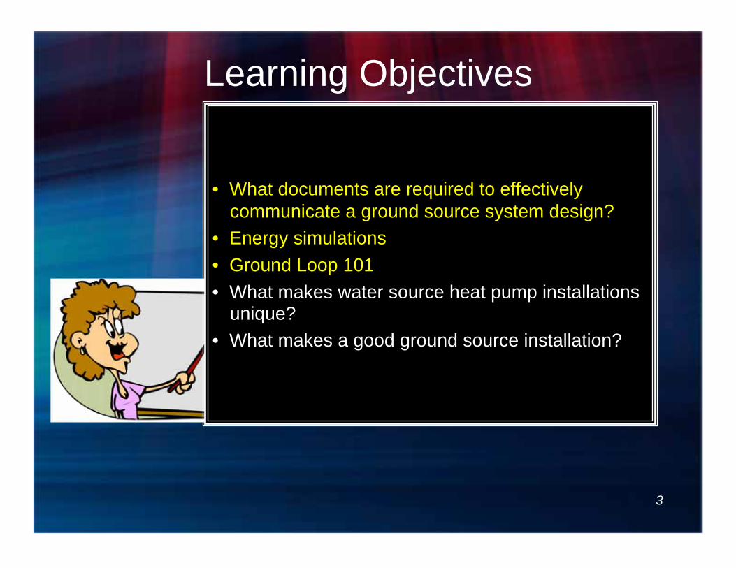
Learning Objectives
• What documents are required to effectively communicate a ground source system design?
• Energy simulations • Ground Loop 101 • What makes water source heat pump installations
unique? • What makes a good ground source installation?
3

Heat Exchanger Configurations
Courtesy Water Furnace
Open Loop Surface Water
Horizontal Bore Vertical Bore
4

Getting Started:
• References – ASHRAE CHAPTER 34 – HVAC
Applications Volume – ASHRAE TC 6.8 Geothermal Heat Pump
and Energy Recovery Applications – Various Journal articles
• Attend seminars like this
5

6
Recommended ASHRAE Design Guide for Commercial and Institutional Buildings

Improving System Design: Simplicity
7
Everything should be made as simple as possible, but not simpler. ~Albert Einstein

Why Simple?
• Designs should be challenged – Everything in the system should be challenged to add
VALUE – Clear project definition and goals
• Energy Efficiency • Ease of Maintenance • Longevity
– What do we NEED in controls?
– What kind of service staff does the client have? – How close are emergency service reosurces?
8

Codes and Standards (US) • International Mechanical Code
– Chapter 12
• IGSHPA - Closed-Loop/Geothermal Heat Pump Systems - Design and Installation Standards
• ASHRAE Standard 90.1 – Variable flow requirements – Isolation valves
• CSA C448 - Design and Installation of Earth Energy Systems
9 9

Ground Source
• What is it? – Efficient system connected with the
ground? • Heat recovery system?
– Recover energy from season to season?
10 10

Are Ground Source Systems a Renewable Energy Source?
11

The earth absorbs nearly half of the sun’s energy.
Ground Source Energy
12

Energy Efficient Heating: Coefficient of Performance
or building
13

Key to Good System Design
A. Is ground source a proper selection?
B. Interior Design C. Physical Constraints of the Ground
14
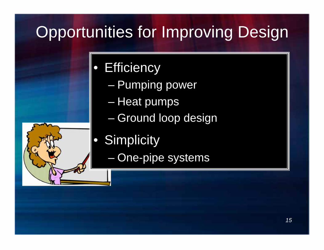
Opportunities for Improving Design
• Efficiency – Pumping power – Heat pumps – Ground loop design
• Simplicity – One-pipe systems
15
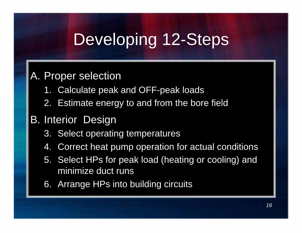
Developing 12-Steps
A. Proper selection 1. Calculate peak and OFF-peak loads 2. Estimate energy to and from the bore field
B. Interior Design 3. Select operating temperatures 4. Correct heat pump operation for actual conditions 5. Select HPs for peak load (heating or cooling) and
minimize duct runs 6. Arrange HPs into building circuits
16

Developing 12-Steps C. Physical Constraints of the Ground
7. Conduct investigation for thermal properties and drilling conditions
8. Determine ground heat exchanger arrangement 9. Calculate optimum ground heat exchanger
dimensions
D. Integration of indoor and outdoor design 10. Iterate to determine optimum operating
temperatures, flows, materials 11. Layout Interior piping for minimum head loss 12. Select pumps and control methodology
17

Is Ground Source A Proper Selection?
A 18
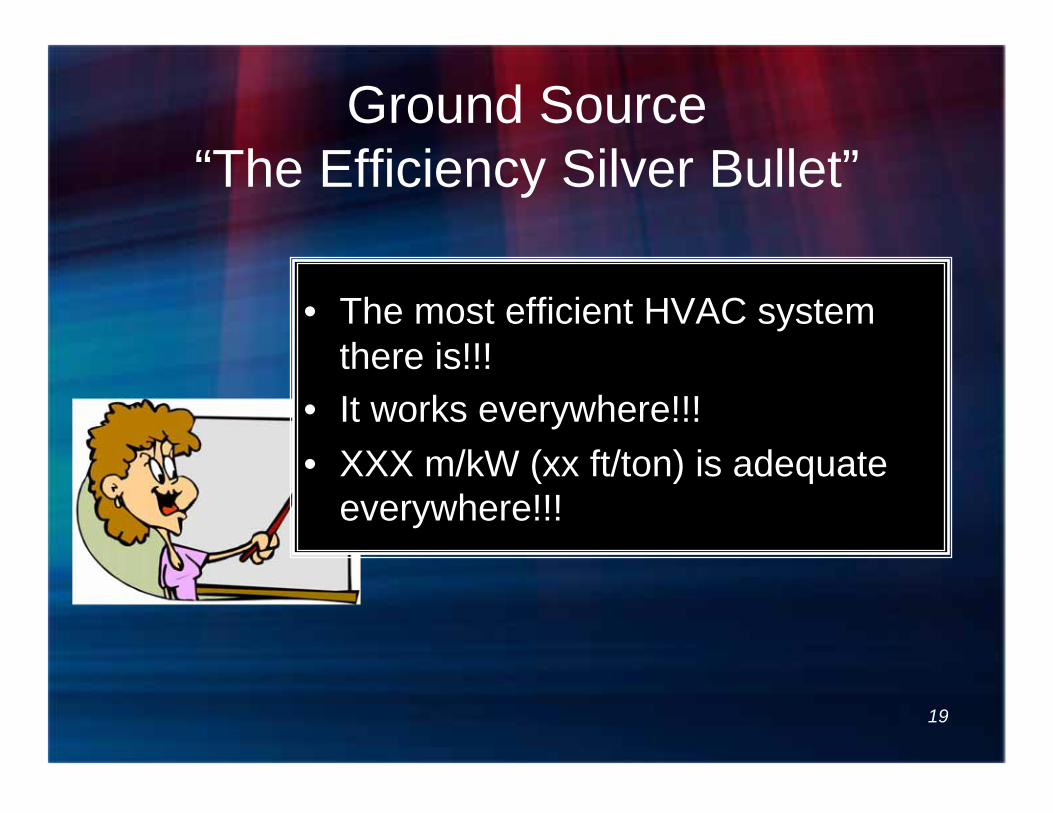
Ground Source “The Efficiency Silver Bullet”
• The most efficient HVAC system there is!!!
• It works everywhere!!! • XXX m/kW (xx ft/ton) is adequate
everywhere!!!
19
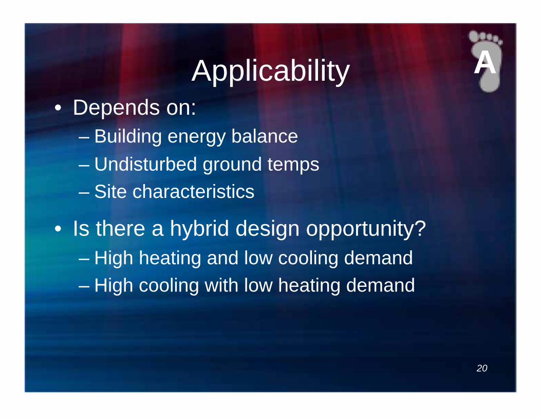
Applicability • Depends on:
– Building energy balance – Undisturbed ground temps – Site characteristics
• Is there a hybrid design opportunity? – High heating and low cooling demand – High cooling with low heating demand
20
A
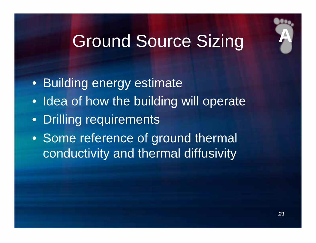
Ground Source Sizing
• Building energy estimate • Idea of how the building will operate • Drilling requirements • Some reference of ground thermal
conductivity and thermal diffusivity
21
A
21

Estimating Energy Usage
• Don’t use ‘Rules of Dumb’ • Equipment efficiency affects bore
field sizing • Perform the Calculations!
– Bin data or 8760 hour simulation to understand the energy coming into the facility and going out
22
A
23
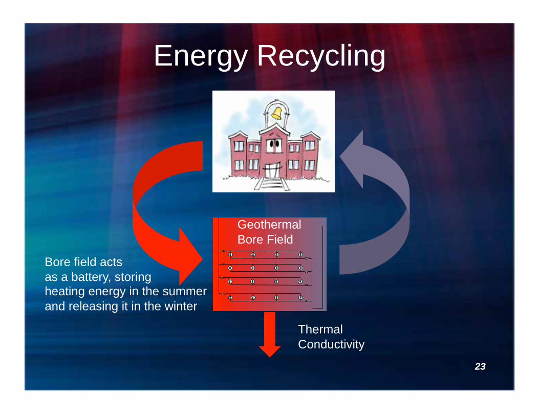
Energy Recycling
Thermal Conductivity
Bore field acts as a battery, storing heating energy in the summer and releasing it in the winter
Geothermal Bore Field
23

24
Real-World Loading
Heat in bore field is likely to increase
Cooling Energy >> Heating Energy
Geothermal Bore Field
24

25
Hybrid Geo-Exchange Systems
Cooling Dominated
FLUID COOLER
Excess Heat
25

Calculate Peak and Off-Peak Loads
1
26

Peak and Off Peak loads
Energy Pulses
27
2

Estimate Energy To and From the Bore Field
2
28

Building uses more energy for cooling than for heating
Seasonal Energy Usage
Seasonally Stored Energy for Cooling
Seasonally Stored Energy for Heating
2
29

10-Month School In Colder Climate
2
30

Interior Design
B 31

Interior Design Concerns
• The interior is where most of the $ are spent on Ground source systems
• Controls should be minimal and add value • Systems operate in a temperature range,
unlike chilled and hot water • Flow should be controlled with Heating
and cooling demand
32

Components of Commercial Ground Source System
33
KEY: Ground Coupled heat exchanger Piping Network Pumps Water source heat pumps Controls
VFD
PD
T
33
Do We Need All of This??????

34
Please do your own pump
pressure drop calculations!!!

Pumping Power
35

Direct Flow without Loop Temp Control
Attributes Heat Pump flow managed by regulator valves Demand Fluid Control Flow Regulator volume control
Challenges System changes manages with flow regulators Pipe Length/ pressure loss Heat/cool energy exchange at bore field Last heat pump can be short of water flow Central pump must be sized for connected load
VFD
PD
36

Reverse Return without Loop Temp Control
Attributes Demand Fluid Control Flow regulator volume
control Equal pipe length to each
heat pump
Challenges System changes managed
with flow regulator valves Pipe Length/ pressure loss Heat/cool energy exchange
at bore field Central Pump must be
sized for connected load
VFD
PD
37

One-Pipe Loop Distributed Primary Secondary Loop
Attributes Demand Fluid Control Secondary pump flow control Little loop temp control Unit by unit diversity No flow regulators Low system pump head Primary pump can be sized for BLOCK load conditions No drive/pump/static control head inefficiency
Challenges Temperature control Pipe Length/pressure loss Last heat pump will have warmer/cooler water
sequencer
T
38

“Heat Recovery, Anyone????”
sequencer
T
Attribute
One-pipe loop allows heat pumps to recover energy from the other units in the system.
Cooling units add heat to the loop, heating units extract heat…
It doesn’t take VRF to have heat recovery.
39

Piping Diagrams
Traditional 2-pipe arrangement
1-pipe arrangement
40
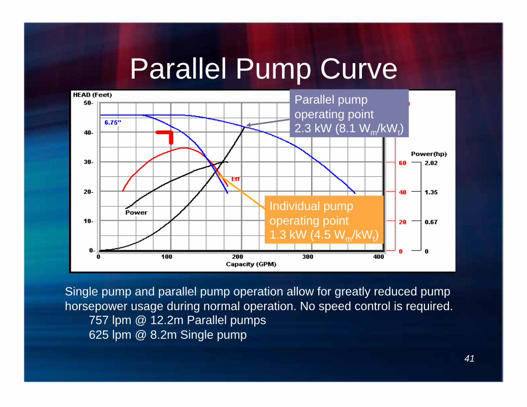
Parallel Pump Curve Parallel pump operating point 2.3 kW (8.1 Wm/kWt)
Individual pump operating point 1.3 kW (4.5 Wm/kWt)
Single pump and parallel pump operation allow for greatly reduced pump horsepower usage during normal operation. No speed control is required.
757 lpm @ 12.2m Parallel pumps 625 lpm @ 8.2m Single pump
41

Heat Pumps
42

Effect of Temperature Control on Performance
43
VFD
PD
T T
System EER
0
5
10
15
20
25
30
30 40 50 60 70 80 90 100 110 120 TEMP (F)
EE
R
2 2.5 3 3.5 4 4.5 5 5.5 6 6.5 7
CO
P
UNIT EER Variable Flow EER UNIT COP Variable Flow COP
43

Water Source Heat Pumps (Self-Contained Approach)
• Many consider: Traditional Equipment • Horizontal Units • Vertical Units • Water to Water • Console Units
44

Water Source HP’s, Traditionally
– “100’s of noisy boxes” above the ceiling – “Require” cooling towers or boilers “to work right” – 2-pipe controlled water distribution
• Water flow control • Motorized isolation valves • Variable speed drives
– Have maintenance issues • Low flow at the end of the distribution • Low temp difference
45

New Paradigm • Many different heat pump systems
• When properly designed and implemented, ground loops can provide all system heat rejection and heat addition
• Water distribution – Traditional 2-pipe variable capacity – Individual circulations – Circulators with central pumps – One pipe
• Lower maintenance costs – Simpler distribution – Managing flow to the units
46

Preliminary Loop Operating Temperatures and Flow
Rate
3
47

Selecting Operating Temperatures • A good starting point
– Undisturbed ground temp • Cooling 10-20ºC (20-35ºF) Above • Heating 5-10ºC (10-15ºF) Below
• Generally, max cooling inlet temps should be below 32.2ºC (90ºF)
• Generally, min heating above 0ºC (Use 7-8ºC to start)
• Final selection based on energy balance • It’s ALL about SYSTEM EER and COP
3
48

Correct Heat Pump Operation for
Actual Conditions
4
49

HP Performance Ratings
• AHRI/ISO/ASHRAE/ANSI 13256-1 - Water-source heat pumps - testing and rating for performance - Part 1: Water-to-air and brine-to-air heat pumps
• EN 14825 - Air Conditioners, Liquid chilling packages and heat pumps, with electrically driven compressors, for space heating and cooling – Testing and rating at part-load conditions and calculations of seasonal performance
50

51
Why Adjust Unit Capacity?
• Under ISO 13256-1 – What is the system fan static pressure for
rating? – What is the pumping energy based upon?
• What are the entering water and air conditions?
4
51

52
Adjusting Unit Capacity • ISO 13256-1
– 0 kPa static pressure – 25ºC (77ºF EWTc) / 0ºC (32ºF) EWTh – 19ºC (66.2ºF) EWB Cooling – 20ºC (68ºF) EDB Heating – Pumping power is included
Some manufacturer’s programs properly adjust the capacity based on your operating conditions, some do not. The point is, capacity adjustment is required to properly select the required equipment.
4
52

53
1 32
Heat Pump Ratings
Select HPs for Peak Load (Heating or Cooling) and
Minimize Duct Runs
5
54

Schedule HP Equipment
55
5
55

Ever see this?
Is this sufficient to define the System requirements?
56

System Definition Requirements • Design parameters
– Flow – Pressure loss – Water quality and
volume – Antifreeze solution and
volume, if required
• Header pipe definition – Material – Diameter – Pressure class rating – Circuit isolation
requirements – Flush/purge provisions
57

System Definition Requirements • Vertical bore definition
– Drilling technique if available – Casing requirements, if any – Bore depth and approximate bore
diameter – Grout Definition
• Thermal Conductivity • Placement method
• Equipment specification – Airflow and pressure drop – Heating and cooling capacity – EER and COP – Water flow and pressure drop – Electrical characteristics – Air filtration specification
58

System Definition Requirements • Inside Building
– Piping specification – Pumping system – Control Specification – System diagram
• Air separation • Compression • Make-up
• Commissioning – Piping installation
inspections and testing
– Purge volume and flow
– Purge procedure – System start-up
procedure – Start-up
documentation
59

Cleaning and Flushing
60

Why Is Pumping Power Important?
61
kWm/100kWt
1.06
1.59
2.12
3.18
4.24
5.30

Physical Constraints of the Ground
C 62

Bore field Arrangements
63

Conduct Investigation for Thermal Properties and
Drilling Conditions
7
64

• Thermal Conductivity • Deep Earth Temperature • Thermal Diffusivity
Thermal Properties for Design
65

The purpose of the test is to determine the physical properties of the ground surrounding the bore hole.
7
66

Typical Bore Detail 9
67
100m
1.2m
(1) U PE100 PN 16
1.9

Calculate GLHX Requirements
9
68

Output from Loop Sizing Routine
9
69

Iterate to Optimize GLHX 1- Balancing length with operating Temperatures
2- Changing to Different Equipment
3- Balancing with Different Equipment
10
70

Determine Ground Heat Exchanger (GLHX)
Arrangement
8
71
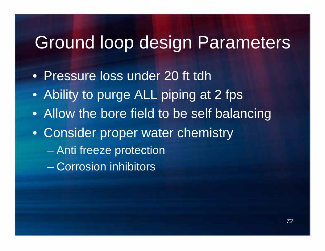
Ground loop design Parameters
• Pressure loss under 20 ft tdh • Ability to purge ALL piping at 2 fps • Allow the bore field to be self balancing • Consider proper water chemistry
– Anti freeze protection – Corrosion inhibitors
72

Basic Header Types • None
– Loop connected directly to equipment
• Close Coupled – U-loops connected to end of the pipe
• Vaults – Reverse return circuits connected to headers in valve vaults
• Reverse Return – Header piping connected to circuits with reverse return piping
and underground valves
• Direct Return – Header piping connected to circuits with direct return piping and
underground valves
73

Close Coupled
74

Vaults
75

Inexperienced design keys
76
Trenching shown on both sides of the string of bores
Balance is affected by lack of reverse return Balancing considerations are problematic
Cross trenching, direct supply and return Fix the balance issue by adding valves

Reverse Return
• Circuits are generally pressure balanced throughout the system
• First supplied is last returned
• Each bore sees the same length of piping material
Reverse Return
77
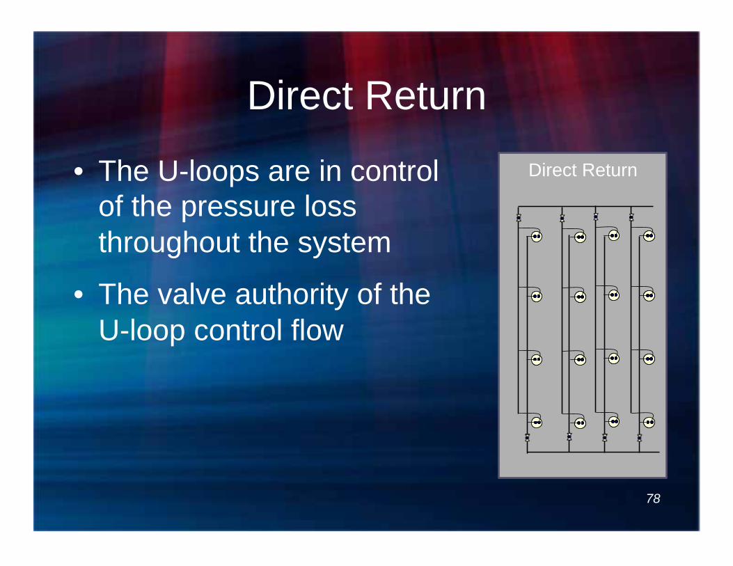
Direct Return
• The U-loops are in control of the pressure loss throughout the system
• The valve authority of the U-loop control flow
Direct Return
78

Vault
Header Configurations Reverse Return Direct Return
79

Header Configurations
Carlson relationship Circuit pressure loss >80% of
overall PD = balanced flow
80

Bore Field Don’ts PVC or Copper
Bentonite Grout
• ---- use vaults • ---- require cross-trenching • ---- use pure Bentonite grout • ---- put bores any closer than 20 ft
(6.1m) OC. • ---- put flow controls on loops
81

Ground Loop Supplement
HDPE SDR 11 UNI-LOOP
Thermally enhanced grout
Total Field Pressure Loss 20 ft H20 (60 kPa)
20 ft (6.1m) MIN Connecting Piping DR 15.5 HDPE
Bore Field and Building Purge Assembly
Use good design practices for header design Close coupled Reverse return Direct return with knowledge of U-loop flow control
82

Energy Expectations
• What happens if you follow these guidelines……
83

Washington Elementary School Belvidere, Illinois
Client: Belvidere Community Unit
School District 100 1201 5th Avenue
Belvidere, IL 61008
815-544-0301
Contact: Michael Houselog, Superintendent
Geothermal HVAC System retrofit 105,000 sq. ft.
60+ classrooms One Pipe Design
Energy recovery ventilation Digital control system
Lighting retrofit throughout the classrooms VRF (Variable Refrigerant Flow) in office area
Annual operating cost savings -$64,000 Renovation over 1 summer
$26.12/ sq ft
84

DOUGLAS ELEMENTARY SCHOOL CLINTON, IL
(Photo of old mechanical room)
Ground Source System
One-Pipe Design Retrofit of existing school
23,980 sq. ft. 15 Classrooms
Approximately 192 students (08-09)
Retrofit cost under $20.00/sq ft Energy usage – 24.83 KBTU/Sq. Ft.
85

LINCOLN ELEMENTARY SCHOOL CLINTON, IL
Ground Source System One-Pipe Design
Retrofit of existing school 29,090 sq. ft.
19 Classrooms 237 students (2007-2008)
Installation cost- Under $20.00/sq ft Annual energy usage-30.1 KBTU/Sq ft
(Photo of old mechanical room)
86

GLENN ELEMENTARY SCHOOL NORMAL, IL
Geothermal HVAC System retrofit One Pipe Design
27,110 sq. ft. 14 classrooms
Installation Cost - $15.75/sq ft Energy Star 99
87

FAIRVIEW ELEMENTARY SCHOOL NORMAL, IL
Geothermal HVAC System retrofit 35,125 sq. ft.
24 classrooms One Pipe Design
Provided heating and cooling system retrofit of existing hot water unit vent system
Operating cost for heating and cooling to be under heating only costs
Energy Star Rating of 98
88

OAKDALE ELEMENTARY SCHOOL NORMAL, IL
Geothermal HVAC System
One-Pipe Design 44,168 sq. ft.
28 classrooms Former operating cost $.99/ft^2
New Operating cost $.76 ft.^2 ($.45 ft^2 lights) $.23/ft.^2/year in HVAC energy savings
Carbon equivalent savings 13-14 #/sq. ft./year Energy Star Rating of 96
89

FRANKLIN ELEMENTARY SCHOOL STERLING, IL
Geothermal HVAC system retrofit One Pipe Design Well Field Design
Water Loop specification and design Control System Design
Specification of test boring Power distribution to
Ground Source System Grades K-2
362 students 36,000 sq. ft. (School was built in 1957.)
23 classrooms 90

JEFFERSON ELEMENTARY SCHOOL STERLING, IL
Geothermal HVAC system retrofit One-Pipe Design Well Field Design Water Loop specification and design Control System Design Specification of test boring Thermal Conductivity Analysis Power distribution to Ground Source
System 39,020 sq. ft. 26 classrooms 427 students (2007)
Client: Sterling Community Unit District No. 5
410 E. LeFevre Sterling, IL 61081
815-626-5050 Contact: Dr. Wil Booker, Superintendent
91

Case Study:
MEM Independence
92

Case Study: MEM Independence
• Missouri Employers Mutual • Independence, Missouri • 557 m2 office facility renovated from
rooftop A/C to Ground Source • First 2 years of results – Less than
impressive $600 per year in additional operating cost.
93

94

Building Energy Consumption
95

As Designed
96

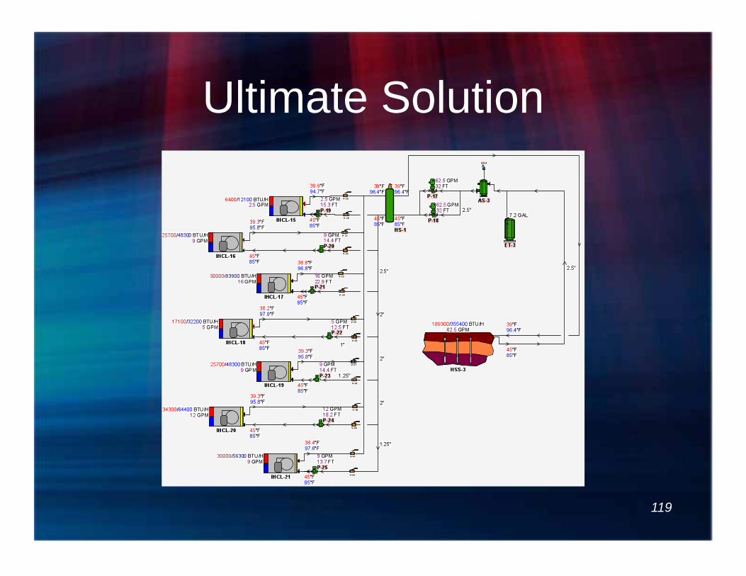
Ultimate Solution
1. Install variable speed circulators to pump the bore field based on temperature differential
2. Install hydronic de-coupler (bridge)
3. Install circulators on each heat pump
1
2
3
97

Ultimate Solution: Building Energy Consumption
98

What have we learned?
99

Lessons Learned • Pumping energy use is not an insignificant
issue. • Decoupling bore field and using
temperature differential to control bore field capacity offers significant benefits.
• Minimizing head on unit circulators is beneficial.
• Low efficiency circulators can provide high efficiency.
100

101
Questions
? ? ?
?
? ?
?
?
? ?
?

HVAC System Designer
• Responsible for – Thermodynamics of the
system – Design of system hydronics – Specification of the entire
HVAC system • The ground HX is part of it!
– The entire system performance
102

Some Background
• Vocabulary • Codes and Standards • References
103 103

ASHRAE HVAC Applications Handbook Chapter 34
Geothermal resources classification by temperature:
High Temperature t > 150 C (300 F) Intermediate Temperature 90 C (195 F) < t < 150C (300 F) Low Temperature t < 90 C (195 F)
• Direct Use • Ground-Coupling
104

Vocabulary
• Ground Source, Geo-Exchange, Ground Coupled – A heating and cooling system that uses the ground as a moderator. The ground acts as a heat sink for heating and cooling energy.
• Geothermal – A heating system that typically uses “hot rocks” or a high temperature aquifer for direct heating or energy production.
• Central Plant – A heating and/or cooling system where multiple facilities are tied together such that the single plant can produce the necessary energy or resource.
105

Vocabulary
• Well – A water-producing bore typically with a submersible pump.
• Bore – An approximately 15 cm (6 in.) hole drilled into the geological formation.
• Borehole, U-loop Heat Exchanger, etc. – A typically vertical u-loop pipe (or ground probe) placed into a bore and grouted into position.
• Bore Field – Accumulation bores designed to be connected with header piping to support a ground source heating and cooling system.
106
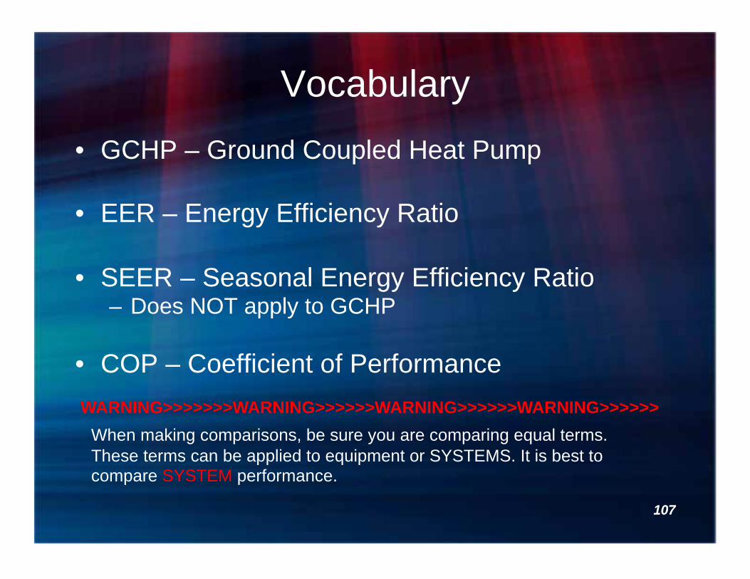
Vocabulary • GCHP – Ground Coupled Heat Pump
• EER – Energy Efficiency Ratio
• SEER – Seasonal Energy Efficiency Ratio – Does NOT apply to GCHP
• COP – Coefficient of Performance
107
When making comparisons, be sure you are comparing equal terms. These terms can be applied to equipment or SYSTEMS. It is best to compare SYSTEM performance.
WARNING>>>>>>>WARNING>>>>>>WARNING>>>>>>WARNING>>>>>>
107

Energy Simulation Should Generate System Parameters
SYSTEM HEATING AND COOLING EFFICIENCY AFFECTS PERFORMANCE, DESIGN AND SIZING
108
1

System Integration
D 109

Layout Interior Piping for Minimum Head Loss
11
110

System Layouts
• Direct Flow – With 3-way control – With 3-way control and VFD – With secondary geo pump – Without loop temp control
• Reverse Return – With 3-way valve control – With secondary geo pump – Without loop temp control
111

Direct Flow with 3-Way Control
Attributes Control of water temp Summer and Winter 30/7 Demand Fluid Control Flow Balance managed by Regulator Valves
Challenges System changes with each device added or subtracted from duty Pipe Length/pressure loss Control valve pressure loss/authority Heat/cool energy exchange at bore field Central pump must be sized for connected load Last Heat Pump can be short of water flow
T T
112

Select Pumps and Control Method,
Determine System Efficiency
12
113

Original Pumping Strategy • Continuous pumping through all heat
pumps
114

Solutions?
• What will make the system operate more efficiently? – Distributed pumping? – ASHRAE 90.1 variable flow solution? – One-pipe solution? – Something different?
115

Solution Considerations: Distributed Pumping
116

Solution Considerations: ASHRAE 90.1
Install motorized isolation valves and variable speed primary pumps
117

Solution Considerations: One-Pipe Solution
Required re-piping of the building
118
Ultimate Solution
119