design of bins and hoppers for the storage of … · design of bins and hoppers for the storage of...
TRANSCRIPT

CASTELL6N (SPAIN)
DESIGN OF BINS AND HOPPERS FOR THESTORAGE OF PARTICULATE MATERIALS.
PROBLEMS ASSOCIATEDWITH THE DISCHARGE OPERATION
J.L. Amoros, G. Mallol, E. Sanchez, J. Garcia
Instituto de Tecnologfa Ceramica (ITC)Asociaci6n de Investigaci6n de las Industrias Ceramicas (AICE)
Universitat Jaume I. Caste1l6n. Spain.
ABSTRACT
In ceramic tile, frit and ceramic colour production processes, large quantities of particulatesolids of different nature are handled, which need to be adequately stored and discharged. Ondischarging these materials, flow stoppages as a result of doming in the bin, size segregation, etc.can occur. Some of these problems can be minimised and even suppressed by appropriate bindesign. In this study, the [enike theory has been applied to bin design for three types of particulatematerials: spray-dried powder, used in porcelain tile manufacture, zinc oxide and quartz, used inceramic frit production. For these materials the maximum angle that the wall needs to form withthe vertical in the bin discharge zone, and the minimum outlet diameter required for appropriate,unbroken material flow during discharge were calculated. The influence was also analysed of thebin surface on the type offlow. Finally, experiments were conducted to verify the usefulness of themethodology testedfor bin design.
P. GI- 41
CASTELL6N (SPAIN)
1. INTRODUCTION
In ceramic manufacture, most of the raw materials used are found as particulatematerials. The daily consumption of particulate materials in the Spanish ceramic tilemanufacturing sector is assessed at around 40,000 tons, which is why it is important toknow the rheological behaviour of these materials during charging and discharging intheir storage containers (basically bins and hoppers).
The rheological behaviour of particulate solids is so complicated that it cannot bedealt with like that of liquids or suspensions, or like that of solids. This all too often leadsto problems in handling: segregation, stoppages in bin or hopper discharges owing todoming, dead spaces in the bins, flooding, etc., which can detrimentally affect theproduction process. These problems can be minimised with appropriate bulk solidsdischarge from bins and hoppers. There are two types of particulate materials discharges:funnel or mass discharges. The existence of one type of flow or the other depends on thenature of the particulate solids and the storage container. Designing a bin with a specifictype of flow therefore requires jointly considering the characteristics of the material andof the bin itself.
1.1 TYPES OF FLOW
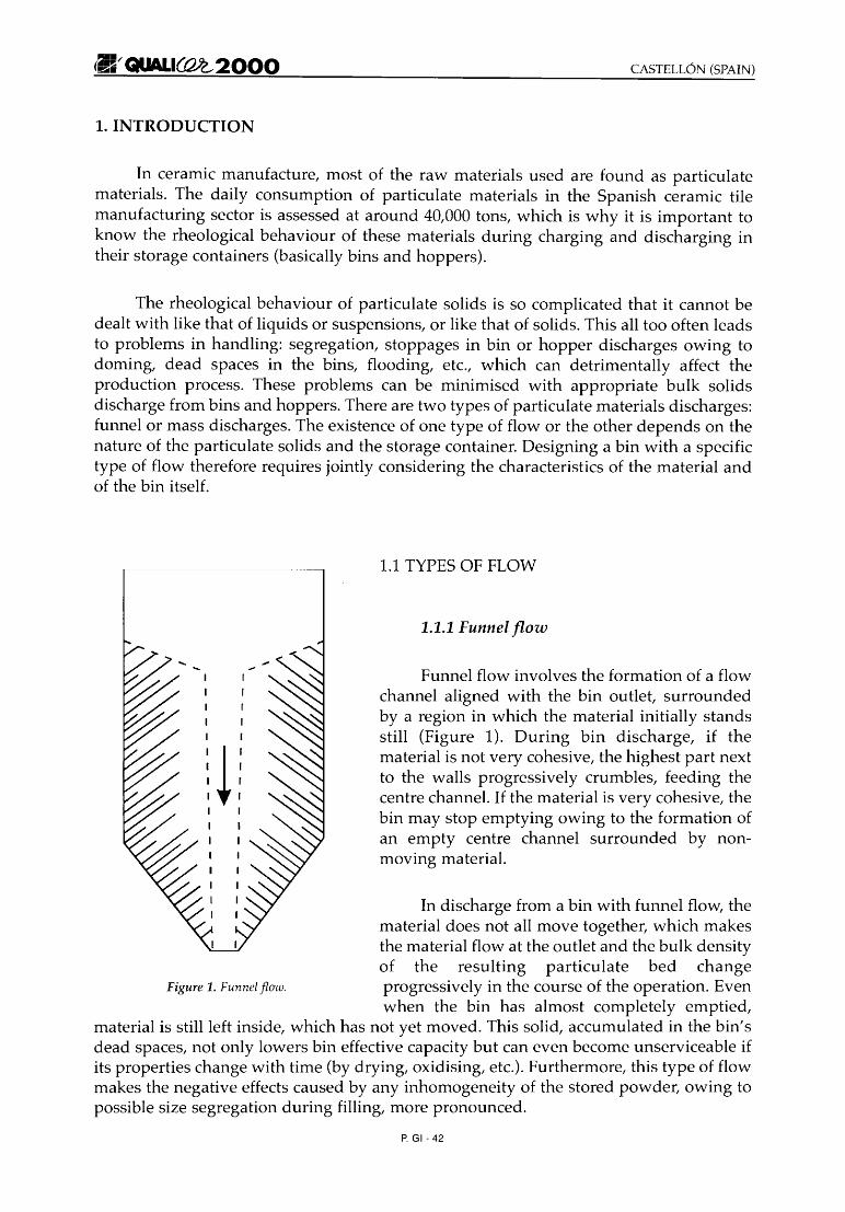
1.1.1 Funnel flow
Funnel flow involves the formation of a flowchannel aligned with the bin outlet, surroundedby a region in which the material initially standsstill (Figure 1). During bin discharge, if thematerial is not very cohesive, the highest part nextto the walls progressively crumbles, feeding thecentre channel. If the material is very cohesive, thebin may stop emptying owing to the formation ofan empty centre channel surrounded by nonmoving material.
In discharge from a bin with funnel flow, thematerial does not all move together, which makesthe material flow at the outlet and the bulk densityof the resulting particulate bed change
Figure 1. Funnel flow. progressively in the course of the operation. Evenwhen the bin has almost completely emptied,
material is still left inside, which has not yet moved. This solid, accumulated in the bin'sdead spaces, not only lowers bin effective capacity but can even become unserviceable ifits properties change with time (by drying, oxidising, etc.). Furthermore, this type of flowmakes the negative effects caused by any inhomogeneity of the stored powder, owing topossible size segregation during filling, more pronounced.
P. GI- 42

CASTELL6N (SPAIN) _,~~ QUALI~2000
One of the few advantages of this type of flow is the decreased wear of bin walls, asfriction is virtually negligible during powder discharge. Moreover, the walls of this typeof bin need to withstand lower pressures, thus requiring less material to build them.
1.1.2 Mass flow
In this type of flow, all the materialcharacteristically moves together during discharge; inparticular, the material next to the wall slides over thewall and empties together with the rest. Oncedischarge starts no particle or agglomerate remains inits original position. They all move, preventing deadspaces from forming. The material that enters the binfirst is the first to leave (first-in, first-out), which tendsto keep a steady powder residence or storage time inthe bin in a continuous process.
Mass flow discharge from the bin is not brokenby channelling, as all the material moves at the sametime. Moreover, the stresses that arise during dischargeare predictable. The bin can therefore be designed toprevent arches from forming and causing dischargestoppages. Figure 2. Mass flow.
The discharge flow rate and density of the resulting powder bed during emptyingare less variable than in the case of funnel flow. Another no less important advantage ofthi s type of flow is the reduction or elimination of the problems that can arise duringcharging associated with segregation. The effect of all the material moving togetherproduces a certain re-mixing that tends to raise the homogeneity of the exiting powder.Thus, bins with mass flow are sometimes recommended as solids blender systems.
Mass Flow
-Eliminates the possibility of flowobstructions
-Minimises the effects associated with sizesegregation
-Renews material (no dead spaces)-Flow is uniform and readily controlled-The density of the discharged powderbed is practically constant
-The whole storage capacity is used (nodead spaces)
Funnel Flow
-Less headspace is required for thesame capacity
-The walls need to w iths tand lowerpressures
-The walls are subject to less abrasion
Table 1. Comparison between mass flow and fu nnel flou: Advantages.
P. GI- 43

CASTELL6N (SPAIN)
1.2. BIN DESIGN
This involves determining the maximum angle that the bin walls form with thevertical in the discharge zone, 8, and the smallest outlet size, D, at which bin dischargeoccurs by uninterrupted mass flow (Figure 3).
1.2.1 Preliminary considerations
1.2.1.1 Outlet obstructions
Bin outlet size must be sufficiently large to keep from becoming obstructed duringdischarge. This phenomenon can stem from doming if the powder is cohesive, or fromblocking up as a result of structures forming if the particles are sufficiently large.
_1---:--"""- D
Figure 3. Design variables.
To keep flow stoppages from arising as a result of the latter mechanism, it sufficesto have an opening one order of magnitude larger than that of the particles oragglomerates making up the powder. The calculation of the discharge diameter to keepstoppages from occurring by the former mechanism is more laborious and is based on thetheory developed by Jenike 11,2,3J in the mid sixties. Some aspects of this theory are dealtwith below.
1.2.1.2 System requirements to preventflow stoppages
Let us analyse what happens to an element of solid in contact with the bin wallduring solids discharge (Figure 4). When the element is located at the top of the bin, it isnot compacted (p=O), as it is subject to no pressure. However, as it descends, it undergoescompaction because the pressure reigning in the bin (p) grows. Figure 4 shows that
[1] JENIKE, A. W. Gravity flow of solids. Bulletin of the University of Utah. No 123, 1961.[2] JENlKE, A. W. Storage and flow of solids. Bulletin of the University of Utah. 53(26), 1964.[3] JJENIKE, A. W.; JOHANSON, J. R. Review of the principles of flow of bulk solids. Cllvl Trans.,?3, 141-146, 1970.
P. GI- 44
(a)
f, s, p (Pa)
,~' QUALI~2000
f, s, p (Pa)
(b)
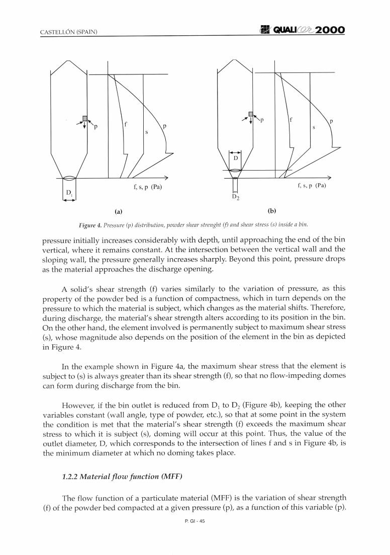
Figure 4. Pressure (p) distribution, powder shear strengh! (j) and shear stress (s) inside a bin.
pressure initially increases considerably with depth, until approaching the end of the binvertical, where it remains constant. At the intersection between the vertical wall and thesloping w all, the pressure generally increases sharply. Beyond thi s point, pressure dropsas the material approaches the discharge opening.
A solid 's shear strength (f) varies similarly to the variation of pressure, as thi sproperty of the powder bed is a function of compactness, which in turn depends on thepressure to which the material is subject, which changes as the material shifts. Therefore,during di scharge, the material's shear strength alters according to its position in the bin.On the other hand, the element involved is permanently subject to maximum shear stress(s), w hose magnitude also depends on the position of the element in the bin as depictedin Figu re 4.
In the example shown in Figure 4a, the maximum shear stress that the element issubject to (s) is always greater than its shear strength (f), so that no flow-impeding domescan form during di scharge from the bin.
However, if the bin outlet is reduced from 0 1 to O2 (Figure 4b), keeping th e otherva riables cons tan t (wall angle, type of powder, etc.), so that at some point in the systemthe condition is met that the material's shear strength (f) exceeds the maximum shearstress to which it is subject (s), doming will occur at this point. Thus, the value of theoutlet di ameter, 0, w hich corresponds to the intersection of lines f and s in Figure 4b, isthe minimum diameter at w hich no doming takes place.
1.2.2 Material flow function (MFF)
The flow function of a particulate material (MFF) is the variation of shear strength(f) of the powder bed compacted at a given pressure (p), as a function of thi s variable (p).
P. GI- 45

(E~QUALI~2000
-COa,"'+-
p (Pa)
Figure 5. Flowfunctions of different materials.
CASTELL6N (SPAIN)
Figure 5 plots the flowfunctions of a series of materials.This property determines therheological behaviour of aparticulate material at differentcompaction pressures and istherefore considered a measure of itsflowability. Thus, the larger theintercept at the vertical axis and thehigher the slope of the plot, the loweris powder flowability. The flowfunction of a particulate material isfound by performing the shearexperiments set out in point 3.3.1.
10 de
1.2.3 The flow factor of the system bin-material iff)
The flow factor (ff) of a bin-particulate material system is the plot of the maximumshear stress (s) that acts on an element of solid stored in a bin versus the pressure to whichit is subjected. [enike observed that in each system, the quotient of both values was constant.
The calculation of the flow factor (ff) involves solving the differential equationsrepresenting the stresses that appear in the bin during discharge. These solutions werepublished by [enike for bins with different geometry, in the form of graphs commonlyknown as flow factor charts (Figure 6).
The flow factor (ff), unlike the material flow function (MFF), is a property of the binmaterial system, so that it depends on certain characteristics of the two. To calculate theflow factor of a system it is necessary to know: the powder effective angle of internalfriction (0), the angle of friction between the material and the bin surface ($), the angle ofthe wall in the bin discharge zone (8) and bin geometry. The value of the material'seffective angle of internal friction (0) and the angle of friction between the material and thebin surface ($) are determined by the shear experiments set out in points 3.3.3 and 3.3.4.
~e-,
<,
.............. Funnel flow<,
<,<,
<,<,
<,<,
<,<,
<,<,
<,<,
8
Figure 6. ]enikegraphfor a cylindricalbin and an angle of internal friction (b) of 30°.
P. GI-46

CASTELL6N (SPAIN)
1.2.4 Calculation of the design variables
1.2.4.1 Calculation of the maximum angle of the bin wall in the discharge zone (8)
The value of 8 is calculated from the flow factor charts (Figure 6). The triangulararea of these graphs represents the conditions for which the material exhibits mass flowduring discharge, in accordance with the Jenike theory. .
The dashed line that separates both regions determines the system's boundaryconditions. Thus, this line represents the pairs of values maximum wall angle (8), angleof friction of the powder-wall system (<p) at which mass flow is found. As a safety margin,it is advisable to use an angle 3° smaller than the estimated angle.
1.2.4.2 Calculation of the minimum outlet diameter (D)
In accordance with Figure 4, on plotting the material flow function (MFF) and theinverse of the system's flow factor (1/ ff) together, Figure 7, the flow condition s-f isobeyed at the intersection of both plots. That is, at this point, the maximum shear stressto which the powder is subject (s) is equal to the strength of the bed (f). This stress is calledthe critical stress (CAS) and its value is used to calculate the minimum bin outlet size. Fora conical bin with a circular opening, minimum outlet size (D) is calculated from theequation:
where:
8 CASD = (2+-)·_·-
60 p.g(1)
0:
8:
CAS
p:
outlet diameter (m)
angle between the vertical and the bin wall in the discharge zone (0)
critical stress (Pa)
powder bed density (kg / m")
CAS
ff
p (Pa)
Figure 7. Flow criterion.
P. GI- 47
CASTELL6N (SPAIN)
2. OBJECTIVE
The objective of this study is to apply the methodology set out above, based on theJenike theory, to the design of bins for the particulate solids used in the ceramic industry,with a view to:
- Reducing the problems caused by the size segregation of spray-dried powder.
- Facilitating the discharge of the highly cohesive materials used in frit production.
- Analysing the influence of the bin surface on material behaviour during discharge.
3. MATERIALS, EQUIPMENT AND EXPERIMENTAL PROCEDURE
3.1 MATERIALS USED
To visually observe size segregation, mixtures of two granulated glazes withdifferent sizes and colours were used. One was coarser, with a black colour and sizeexceeding 500 Jim. The other was finer, with a white colour and sizes below 500 Jim. Themean sizes of the two granulates were 800 Jim and 350 Jim respectively.
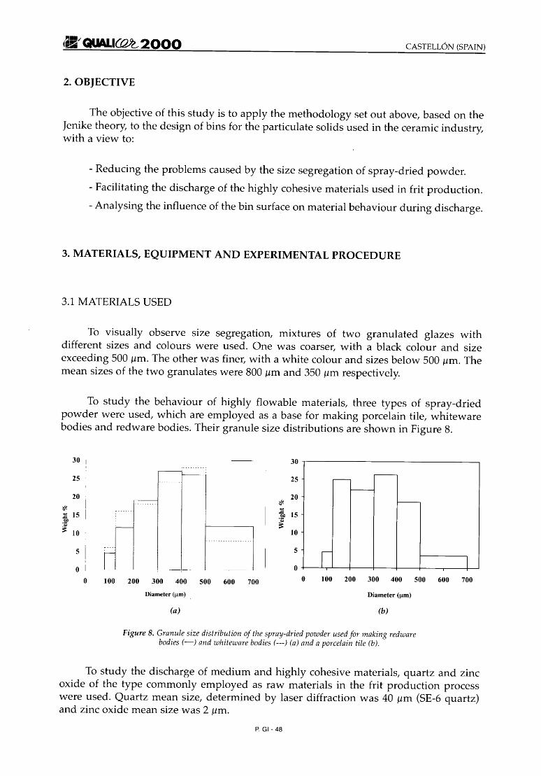
To study the behaviour of highly flowable materials, three types of spray-driedpowder were used, which are employed as a base for making porcelain tile, whitewarebodies and redware bodies. Their granule size distributions are shown in Figure 8.
-~
-f---------
I I5
oo 100 200 300 400 500 600 700
10
25
30
5 !
oo 100 200 300 400 500 600 700
25
20
30
~
:c 15ClI
~ 10
Diameter (urn) . Diameter (urn)
(a) (b)
Figure 8. Granule size distribution of the spray-dried powder usedfor making redwarebodies (-) and whiteware bodies (---) (a) and a porcelain tile (b).
To study the discharge of medium and highly cohesive materials, quartz and zincoxide of the type commonly employed as raw materials in the frit production processwere used. Quartz mean size, determined by laser diffraction was 40 Jim (SE-6 quartz)and zinc oxide mean size was 2 Jim.
P. GI- 48
CASTELL6N (SPAIN)
3.2 EQUIPMENT USED
3.2.1 Shear cells
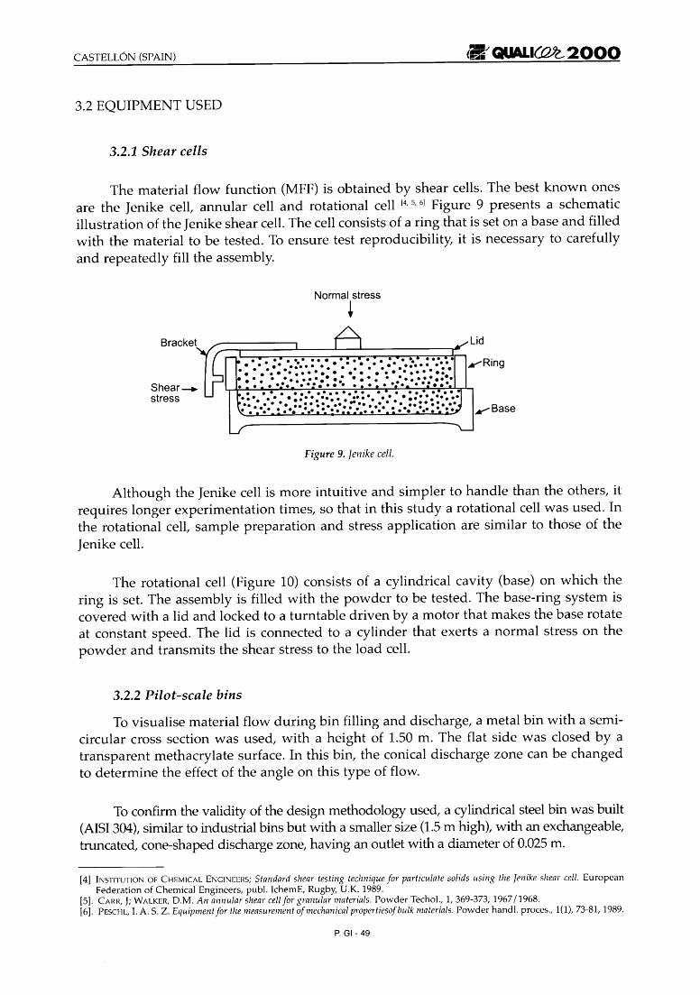
The material flow function (MFF) is obtained by shear cells. The best known onesare the Jenike cell, annular cell and rotational cell 14,5,6] Figure 9 presents a schematicillustration of the [enike shear cell. The cell consists of a ring that is set on a base and filledwith the material to be tested. To ensure test reproducibility, it is necessary to carefullyand repeatedly fill the assembly.
Normal stress
+Bracket
.... : : : : : : : .• • • • •• • e. •• • • •• • • ••••••• e •••••• : •
: .: ..-.t:-::...•: :.: :.: ..- :..••:~.. ... . . .... .. .. . .. .. . - -::••:•• ::.:. :.:. : •••:. :-:: :•• • : .:. :.::: •••: ....... Base
Figure 9. [enike cell.
Although the [enike cell is more intuitive and simpler to handle than the others, itrequires longer experimentation times, so that in this study a rotational cell was used. Inthe rotational cell, sample preparation and stress application are similar to those of theJenike cell.
The rotational cell (Figure 10) consists of a cylindrical cavity (base) on which thering is set. The assembly is filled with the powder to be tested. The base-ring system iscovered with a lid and locked to a turntable driven by a motor that makes the base rotateat constant speed. The lid is connected to a cylinder that exerts a normal stress on thepowder and transmits the shear stress to the load cell.
3.2.2 Pilot-scale bins
To visualise material flow during bin filling and discharge, a metal bin with a semicircular cross section was used, with a height of 1.50 m. The flat side was closed by atransparent methacrylate surface. In this bin, the conical discharge zone can be changedto determine the effect of the angle on this type of flow.
To confirm the validity of the design methodology used, a cylindrical steel bin was built(AISI304), similar to industrial bins but with a smaller size (1.5m high), with an exchangeable,truncated, cone-shaped discharge zone, having an outlet with a diameter of 0.025 m.
[4] INSTITUTION OF CHEMICAL ENGINEERS; Standard shear testing techniquefor particulate solids using the [enike shear cell. EuropeanFederation of Chemical Engineers, publ. IchemE, Rugby, U.K. 1989.
[5]. CAlm, J; WALKER, D.M. An annular shearcellfor granular materials. Powder Techol., 1,369-373, 1967/1968.16]. PESCHL, I. A. S. Z. Equipmentfor the measurement of mechanical propertiesofbulk materials. Powder handl. proces., 1(1), 73-81, ]989.
P. GI- 49

,~ QUALlCOYG,2000
Shear stresstransmitting arm
~~~=::J
Retainer
Ring
StandTurntable
Figure 10. Rotational cell..
3.3 EXPERIMENTAL PROCEDURE
To calculate design variables, D and 8, it is necessary to experimentally determinethe following parameters: material flow function (MFF), the material' s angle of internalfriction (6) and the angle of friction between the material and the bin w all (ep) 17,81
3.3.1 Determination of the material floto function (MFF)
Thi s is determined from the flow curves measured using the she ar cell. These arefound by the following experimental procedure:
- A metal ring is set on the cell base together with an accessory that allows raisingthe heigh t of the cylindrical cavity of the base-ring system. The assembly is filledwith the powder to be tested.
- A pressure is applied to the powder bed during a set time (pre-consolidationpressure) . The accessory is then withdrawn, the powder is scraped off flush withthe height of the ring, the lid is placed on the assembly, the base is fastened to theturntab le and the ring is locked in place .
- The programmed consolidation pressure (am) is applied to the lid whilesimultaneously rotating the base at a constant speed. The rotating movementproduces a progressive rise in the shear stress, which acts on the powder bed in theplane between the base and the ring until reaching a value (-tm ) at which materialflow initiates.
[7] WILLI AMS, j .e.; The storage and flow of powders. In: RHODES, M. j ., (ed .). Prin ciples of pow der s technology. Chic he ster: joh nWiley, 1990.
[8]. SVAROVSKY, L. Powder testing guide. London: Elsevier. 1987 .
P. GI - 50

CASTELL6N (SPAIN)
- Subsequently, without withdrawing the powder from the cell, lower pressures (a)than the consolidation pressure (am) are applied to the lid, repeating theexperiment described. Pairs of values (o, 1:) are thus found, which form the flowcurve of the powder bed compacted at normal stress ami (Figure 11).
- The procedure is then repeated, applying different consolidation pressures(usually 5), to obtain a set of flow curves of the powder bed on compacting atdifferent pressures.
Normal stress (Pa)
Figure 11. Flow curve of a particulate material.
3.3.2 Calculation of the material flow function (MFF)
It can be shown, based on applying tensor calculation to soil mechanics, that foran element of solid sliding down the inside of a bin by mass flow, with compactnessPi' the value of the pressure that consolidates the powder bed (p) and its strength (f)can be calculated from the flow curve found for a powder bed with the samecompactness (p).19, 10, 11, 12J
Pi o (Pa)
Figure 12. Determination of a point (Pi! f,) of theflow function.
[9] FEODOSIEV, V. I. Resisienciade materiales. Ted. Moscu : Ed. MiT, 1980.[10] ONODA, G. Y; JANNEY, M. A; Application of soil mechanics concepts to ceramics particulateprocessing. In . Chin, G.Y Advances in
Powders Technology.Ohio: ASM, 1981.[11] ATKINSON, J.H.; BRANSBY, P.L.; The Mechanics of soils. An introduction to critical state soil mechanics. London: Ed. McGraw-Hill
University Series in Civil Engineering, 1978[12] BROWN, R.L.; RICHARDS, J.e.; Principesof powder mechanics. Pergamon Press, 1970
P. GI- 51
.~" QUALICQJ2.,2000 CASTELL6N (SPAIN)
Thus, semi-circles are drawn tangential to the flow curve corresponding to acompactness of the bed Pi' obtained on applying a consolidation stress (am)' which gothrough the origin of the co-ordinates and through the end point of the curve (Figure 12).The intersections of these circles with the horizontal axis determine the bed's strength (f)and consolidation pressure (pJ
Applying the same procedure for each flow curve yields pairs of values (p.f) thatconstitute the material's flow curve. This curve represents the bed's strength (f), atdifferent compactness values (p) as a function of the consolidation pressure at which theywere obtained (p).
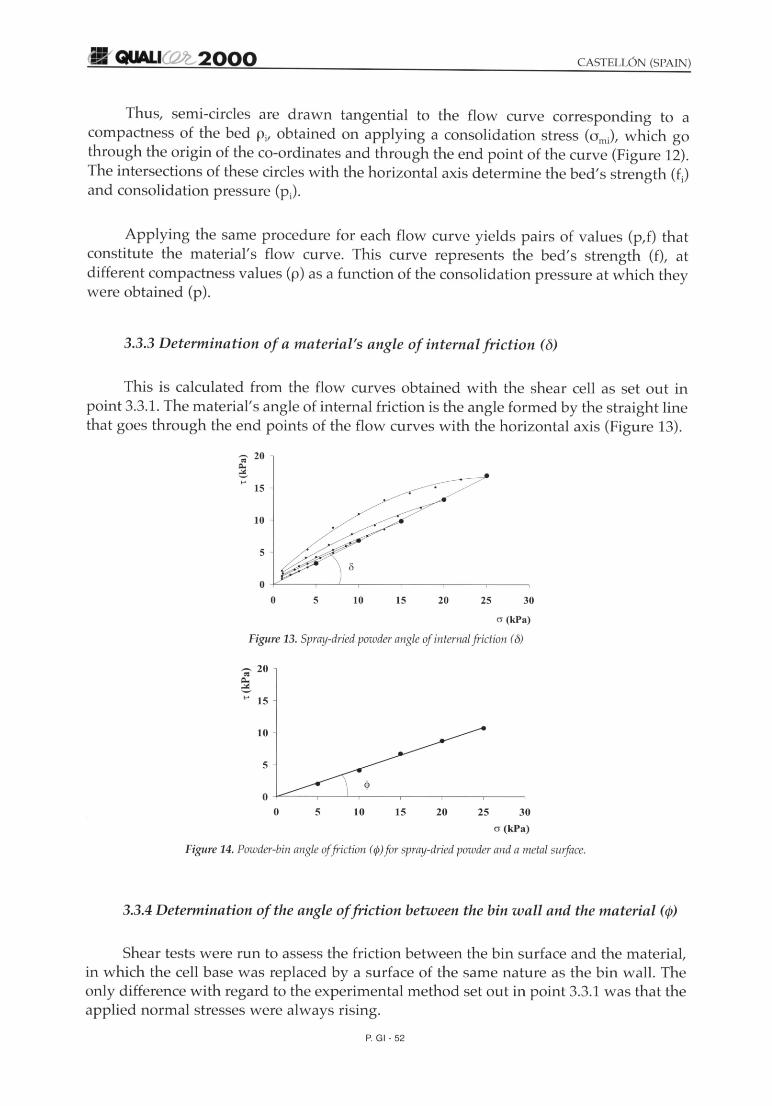
3.3.3 Determination of a material's angle of internal friction (0)
This is calculated from the flow curves obtained with the shear cell as set out inpoint 3.3.1. The material's angle of internal friction is the angle formed by the straight linethat goes through the end points of the flow curves with the horizontal axi s (Figure 13).
";' 20
~to'
15
10
5
30252015105
O --!-"=---------r-~~---r---.--------r-----,
ocr (kPa)
Figure 13. Spray-dried powder angle of internal friction (0)
'2 20
6to' 15
10
5
2015105
o -l-~---.---L-,---..,.------,-----,------,
o 25 30
o (kPa)
Figure 14. Powder-binangleof friction (¢) for spray-driedpowder and a metal surface.
3.3.4 Determination of the angle offriction betuieen the bin wall and the material (cp)
Shear tests were run to assess the friction between the bin surface and the material,in which the cell base was replaced by a surface of the same nature as the bin wall. Theonly difference with regard to the experimental method set out in point 3.3.1 was that theapplied normal stresses were always rising.
P. GI - 52

CASTELL6N (SPAIN)
The plot of the evolution of the shear stress that causes material flow over the binsurface versus applied pressure yields a straight line (Figure 14). The angle that thisstraight line forms with the horizontal axis is $.
4. RESULTS AND DISCUSSION
4.1 STUDY OF SIZE SEGREGATION DURING THE HANDLING OF A POWDERAGGLOMERATE. INFLUENCE OF TYPE OF FLOW DURING BIN DISCHARGEON THE HOMOGENEITY OF THE EXITING MATERIAL.
On filling bins with powder agglomerate, hence with high flowability, segregationusually occurs when the size distribution is quite heterogeneous. If the bin is filled from afixed pour point, which is the most common situation, the material accumulates at thefalling point, forming a heap. The small agglomerates are held up in the gaps that formbetween the agglomerates, producing a column under the pour point. However, the largeagglomerates continue to roll and tumble to the sides of the bin, concentrating at the walls.
During bin discharge the greater or lesser homogeneity of the powder may dependon the type of flow. Thus, if the bin empties with funnel flow, the first agglomerates to bedischarged will be the finest and the last the coarsest, which means that the exitingpowder granule size distribution varies with time. On the other hand, if bin dischargeoccurs by mass flow, the re-mixing effect at the outlet will reduce or even suppress thesegregation occurring during filling [13,14,15, 161.
4.1.1 Visual determination of the segregation arising during bin filling
To study the segregation that takes place on filling a bin with highly flowablegranular materials, a 50-50 mixture (by weight) was used of the granulated glazes withdifferent colours and sizes in the semi-cylindrical bin described above. Figure 15 presentssome of the most representative images, filmed by a video camera. It can be observed thaton keeping a fixed filling point, a little heap forms as the bin is filled, in which the finer(white) granules gather in the centre, while the coarser (black) ones roll over these toreach the bin walls, concentrating in this area as expected.
4.1.2 Influence of type offlow during bin discharge on exiting powder characteristics
A series of filling and emptying experiments was performed using the abovementioned transparent bin and mixture of granulated glazes, with two discharge cones
[13] CARSON, J.W.; Royal, T.A.; Goodwill, D. J. Undestanding and eliminating particlesegregation problems. Bulk solids handl., 6(1),139-144, 1986.
[14] GOODWILL, D. J.Solving particlesegregation problems in bins. Process eng., 70(6), 49-50, 1989.[15] WILLIAMS, J.e. The designof solids handling plants to minimize the effects of particle segregation. Powdex 92. Madrid, 7-8 Mayo 1992[16] CLACUE, K.; Wrigth, H. Minimising segregations ill bunkers. ASME Paper No 72-MH-16. Second Symposium on storage and
flow of solids, Chicago. Sept. 1972.
P. GI- 53
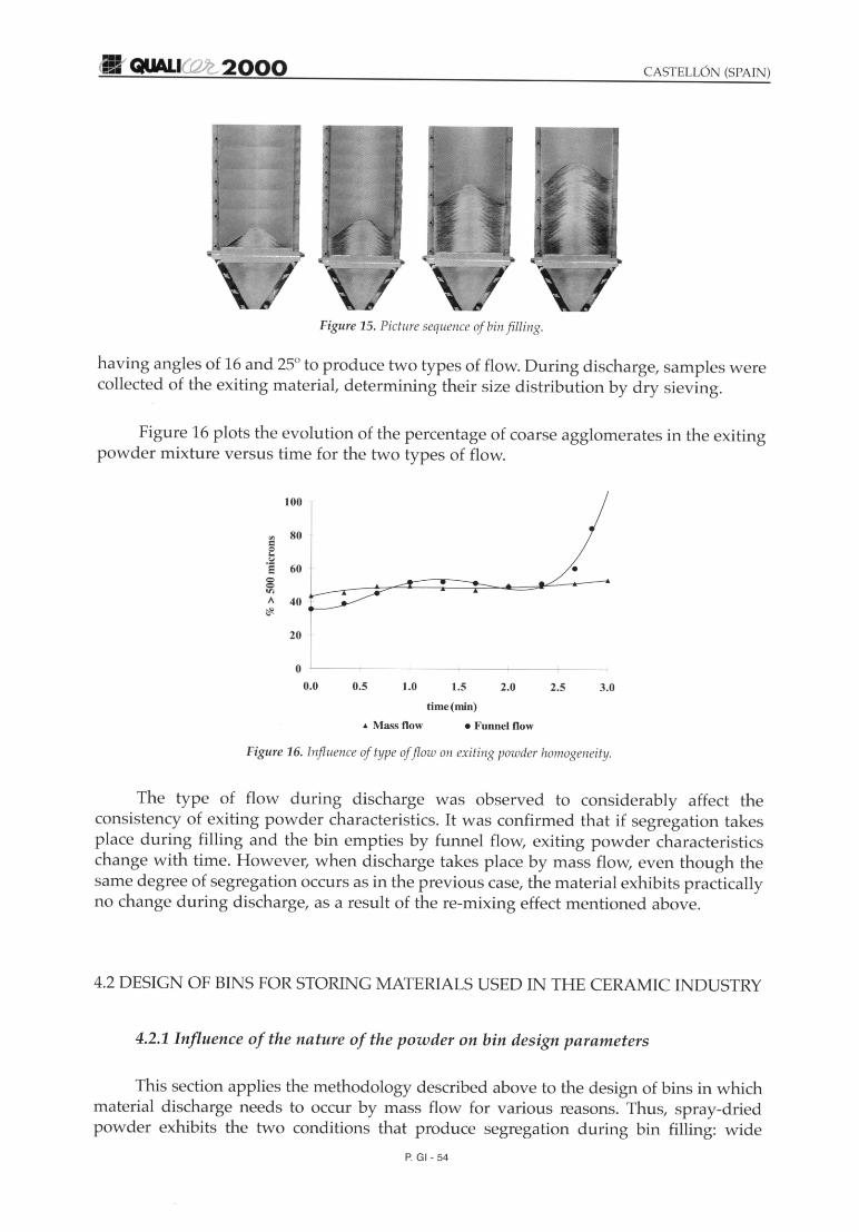
Figure15. Picture sequence of bin filling.
having angles of 16 and 25° to produce two types of flow. During discharge, samples werecollected of the exiting material, determining their size distribution by dry sieving.
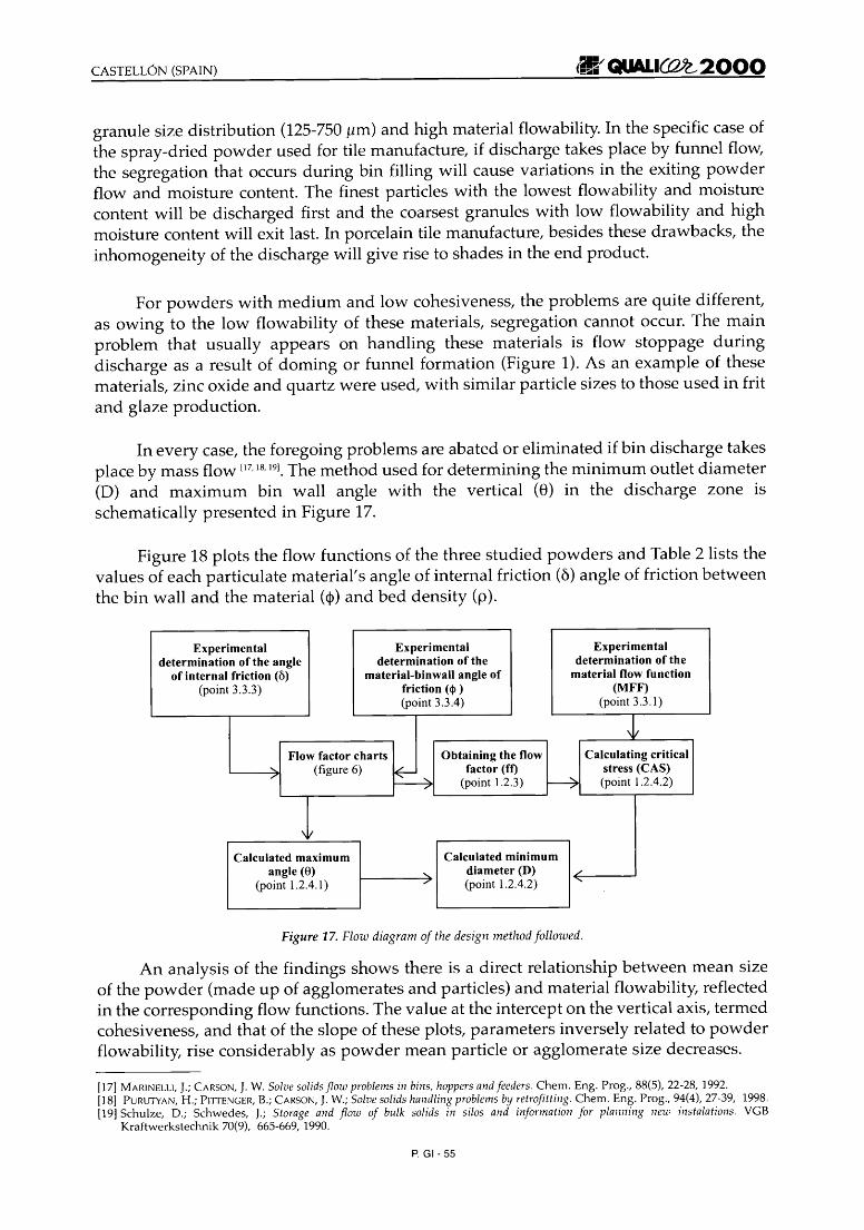
Figure 16 plots the evolution of the percentage of coarse agglomerates in the exitingpowder mixture versus time for the two types of flow.
100
'" 80c0...<:.I·s 60
==II)A
~
20
0
0.0 0.5 1.0 1.5
time (min)
2.0 2.5
•
3.0
• Mass flow • Funnel flow
Figure16. Influence of type of flow on exiting powder homogeneity.
The type of flow during discharge was observed to considerably affect theconsistency of exiting powder characteristics. It was confirmed that if segregation takesplace during filling and the bin empties by funnel flow, exiting powder characteristicschange with time. However, when discharge takes place by mass flow, even though thesame degree of segregation occurs as in the previous case, the material exhibits practicallyno change during discharge, as a result of the re-mixing effect mentioned above.
4.2 DESIGN OF BINS FOR STORING MATERIALS USED IN THE CERAMIC INDUSTRY
4.2.1 Influence of the nature of the powder on bin design parameters
This section applies the methodology described above to the design of bins in whichmaterial discharge needs to occur by mass flow for various reasons. Thus, spray-driedpowder exhibits the two conditions that produce segregation during bin filling: wide
P. GI- 54
CASTELL6N (SPAIN) =/QUALI~2000granule size distribution (125-750 tim) and high material flowability. In the specific case ofthe spray-dried powder used for tile manufacture, if discharge takes place by funnel flow,the segregation that occurs during bin filling will cause variations in the exiting powderflow and moisture content. The finest particles with the lowest flowability and moisturecontent will be discharged first and the coarsest granules with low flowability and highmoisture content will exit last. In porcelain tile manufacture, besides these drawbacks, theinhomogeneity of the discharge will give rise to shades in the end product.
For powders with medium and low cohesiveness, the problems are quite different,as owing to the low flowability of these materials, segregation cannot occur. The mainproblem that usually appears on handling these materials is flow stoppage duringdischarge as a result of doming or funnel formation (Figure 1). As an example of thesematerials, zinc oxide and quartz were used, with similar particle sizes to those used in fritand glaze production.
In every case, the foregoing problems are abated or eliminated if bin discharge takesplace by mass flow 117
, 18,191. The method used for determining the minimum outlet diameter
(D) and maximum bin wall angle with the vertical (8) in the discharge zone isschematically presented in Figure 17.
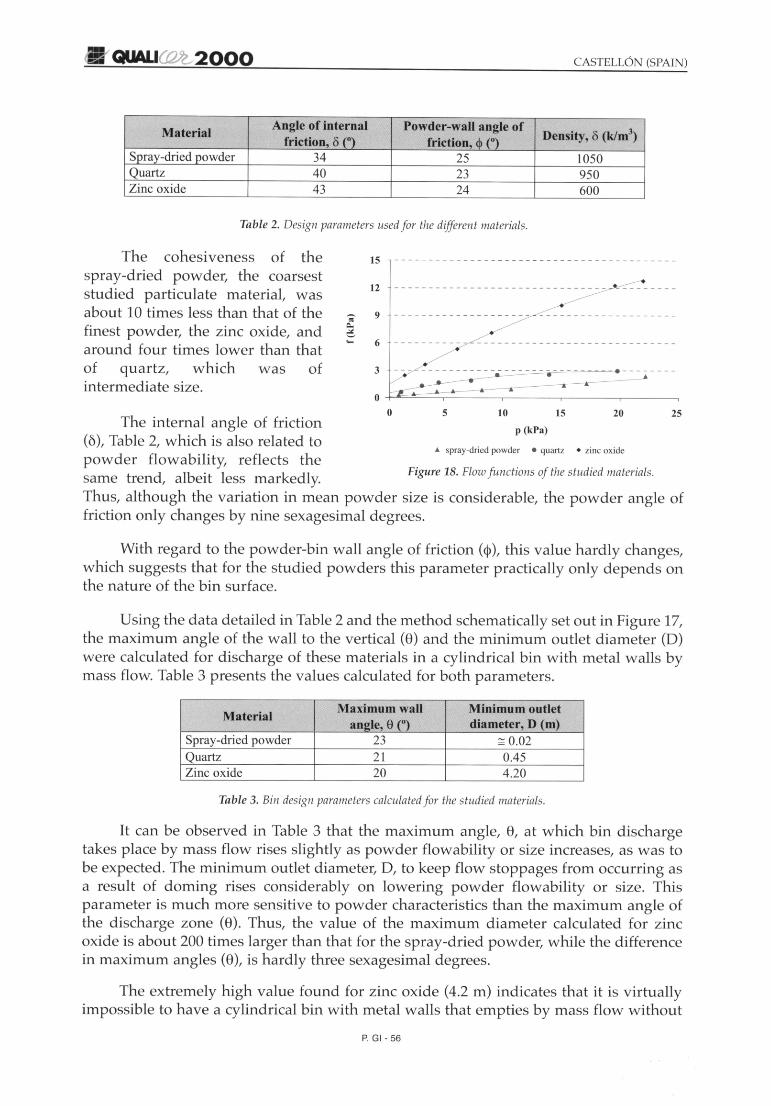
Figure 18 plots the flow functions of the three studied powders and Table 2 lists thevalues of each particulate material's angle of internal friction (0) angle of friction betweenthe bin wall and the material (<I» and bed density (p).
Experimental Experimental Experimentaldetermination of the angle determination of the determination of the
of internal friction (6) material-binwall angle of material flow function(point 3.3.3) friction (<I> ) (MFF)
(point 3.3.4) (point 3.3.1)
~Flow factor charts Obtaining the flow Calculating critical
"- (figure 6)
~factor (ft) stress (CAS)
;'
(point 1.2.3) ~ (point 1.2.4.2)
\II
Calculated maximum Calculated minimumangle (8) <; diameter (D) ./
(point 1.2.4.1) ;' (point 1.2.4.2) ......
Figure 17. Flow diagram of the design methodfollowed.
An analysis of the findings shows there is a direct relationship between mean sizeof the powder (made up of agglomerates and particles) and material flowability, reflectedin the corresponding flow functions. The value at the intercept on the vertical axis, termedcohesiveness, and that of the slope of these plots, parameters inversely related to powderflowability, rise considerably as powder mean particle or agglomerate size decreases.
[17] MARINELLI, J.; CARSON, J.W. Solve solidsflow problems in bins, hoppers and feeders. Chern. Eng. Prog., 88(5), 22-28, 1992.[18] PURUTYAN, H.; PllTENGER, B.; CARSON, J.W.; Solve solids handling problemsby retrofitting. Chern. Eng. Prog., 94(4), 27-39, 1998.[19] Schulze, D.; Schwedes, J.; Storage and flow of bulk solids in silos and information for planning new instalations. VGB
Kraftwerkstechnik 70(9), 665-669, 1990.
P. GI- 55
.~/ QUALI(Q)2.,2000
MaterialAngle of internal Powder-wall angle of
Density, o (k/nr')friction, 0 (O) friction, <I> (O)Spray-dried powder 34 25 1050Quartz 40 23 950Zinc oxide 43 24 600
Table 2. Design parameters usedfor the different materials.
The cohesiveness of thespray-dried powder, the coarseststudied particulate material, wasabout 10 times less than that of thefinest powder, the zinc oxide, andaround four times lower than thatof quartz, which was ofintermediate size.
15 - - - - - - - - - - - - - - - - - - - - - - - - - - - - - - - - - - - - - - - - -
2520
• zinc oxide
15
p (kPa)
105
• spray-dried powder • quartz
Figure 18. Flowf unctions of the studied materials.
oThe internal angle of friction
(6), Table 2, which is also related topowder flowability, reflects thesame trend, albeit less markedly.Thus, although the variation in mean powder size is considerable, the powder angle offriction only changes by nine sexagesimal degrees.
With regard to the powder-bin wall angle of friction (cp), this value hardly changes,which suggests that for the studied powders this parameter practically only depends onthe nature of the bin surface.
Using the data detailed in Table 2 and the method schematically set out in Figure 17,the maximum angle of the wall to the vertical (8) and the minimum outlet diameter (0)were calculated for discharge of these materials in a cylindrical bin with metal walls bymass flow. Table 3 presents the values calculated for both parameters.
MaterialMaximum wall Minimum outlet
angle, e (O) diameter, D (m)Spray-dried powder 23 ~ 0.02Quartz 21 0.45Zinc oxide 20 4.20
Table 3. Bin design parameters calculatedfor the studied materials.
It can be observed in Table 3 that the maximum angle, 8, at which bin dischargetakes place by mass flow rises slightly as powder flowability or size increases, as was tobe expected. The minimum outlet diameter, 0, to keep flow stoppages from occurring asa result of doming rises considerably on lowering powder flowability or size. Thisparameter is much more sensitive to powder characteristics than the maximum angle ofthe discharge zone (8). Thus, the value of the maximum diameter calculated for zincoxide is about 200 times larger than that for the spray-dried powder, while the differencein maximum angles (8), is hardly three sexagesimal degrees.
The extremely high value found for zinc oxide (4.2 m) indicates that it is virtuallyimpossible to have a cylindrical bin with metal walls th at empties by mass flow without
P. GI- 56

.~ f' QUALI~2000
doming. The discharge of bins containing highly cohesive materials like the studiedmaterial, will need to be assisted by installing systems to facilitate discharge, bypractically instantly breaking up the domes as they form (vibrators, etc.).
4.2.2 Effect of the nature of the bin inner wall on design parameters
To determine the effect of the nature of the bin inner surface on the maximum conewall angle (8) and on the minimum outlet diameter (D), a series of experiments wasconducted with the Teflon-spray-dried powder system, to determine the angle of frictionbetween both materials. Following the same procedure as in the foregoing section (Figure17), the design parameters were determined of a bin with a Teflon-lined inner wall. Table4 presents the outcomes.
Inner wall surface materialDesign parameters
Teflon Metal
Powder-wall angle of15 25friction, <I> (0)
Maximum wall angle,35 23ee)
Minimum outlet~ 0.02 ~ 0.02
diameter, D (m)
Table 4. Design parameters used for the studied materials.
iii
Figure 19. Effect ofthe nature of thesurface all the
required maximumwall angle.
"It was verified that for the studied spray-dried powder, the maximum wall angle inthe bin discharge zone (8) rose considerably on reducing the friction between the powderand wall surface (<\l), which raised bin capacity without modifying bin height (Figure 19).
4.3 Validation of the bin design methodology
In view of the minimum diameter outlet values found for the various materials(Table 3), a series of experiments was performed on a pilot scale with spray-dried powderto verify the validity of the design method used.
Two exchangeable cones were built, with discharge angles of 18° and 26°respectively, below and above the design angle, which fitted the semi-circular bindescribed above. To visualise the type of material flow during discharge, the bin wasalternately filled with red and white-coloured spray-dried powder, forming layers ofdifferent colours. Bin discharge with the two cone angles was filmed with a video camera.Figures 20 and 21 present some of the most illustrative pictures.
It was found that on using a slightly larger cone angle than the calculated one,powder discharge was by funnel flow (Figure 20), whereas on using a smaller cone anglethan the theoretical one, discharge was dearly by mass flow (Figure 21). Both findingsconfirm the validity of the design method used.
P. GI- 57

Figure 20. Picture sequenceof bin discharge fu nnel flow.
Figure 21. Picture sequence of bin discharge with mass flow.
5. CONCLUSIONS
The following conclusions can be drawn from the study:
- If a fixed pour point is held during bin filling, which is a fairly common situation,solids segregation occurs owing to the different trajectories followed by theparticles in accordance with their size. This problem increases as the flowabilityand difference in particle size of the particulate material rises.
- The variation in bin exiting powder characteristics, owing to the segregation thattakes place during bin filling, is abated or suppressed if powder discharge takesplace by mass flow, which depends on the discharge zone angle. For the spraydried powder used in the study, this angle was found to be 23° for a cylindricalmetal bin.
- Continuous discharge of a cohesive material can be achieved by designing a binthat empties by mass flow and has a suitable outlet diameter. Both parameters canbe determined when the rheological behaviour of the material is known, applyingthe bin design methodology.
- The surface properties of the bin wall affect the outlet diameter and the angle ofmass flow. Raising the angle of friction between the material to be stored in the binand the bin wall increases the minimum outlet diameter required to keep domesfrom forming and reduces the maximum angle of mass flow.
P. GI- 58