design of an acoustic silencer with microperforated
TRANSCRIPT

Purdue UniversityPurdue e-Pubs
Publications of the Ray W. Herrick Laboratories School of Mechanical Engineering
8-11-2015
Design of an Acoustic Silencer withMicroperforated Elements Considering FlowEffectsJ Stuart BoltonPurdue University, [email protected]
Seungkyu [email protected]
Follow this and additional works at: http://docs.lib.purdue.edu/herrick
This document has been made available through Purdue e-Pubs, a service of the Purdue University Libraries. Please contact [email protected] foradditional information.
Bolton, J Stuart and Lee, Seungkyu, "Design of an Acoustic Silencer with Microperforated Elements Considering Flow Effects"(2015). Publications of the Ray W. Herrick Laboratories. Paper 109.http://docs.lib.purdue.edu/herrick/109

D e s i g n o f a n a c o u s t i c s i l e n c e r w i t h m i c r o p e r f o r a t e d e l e m e n t s c o n s i d e r i n g f l o w e f f e c t s
S E U N G K Y U L E E A N D J . S T U A R T B O L T O N
R A Y W . H E R R I C K L A B O R A T O R I E S , P U R D U E U N I V E R S I T Y
I N T E R - N O I S E 1 5 , S A N F R A N C I S C O , U S A
8 / 1 1 / 2 0 1 5 T U E S D A Y

Acknowledgement
2
3M Company, USA
The authors acknowledge the support of 3M Corporation through the provision of
materials for the fan noise experiments and for the financial support of this work.

Previous work (Presented at Noise Con 2014)
3
A cylindrical MPP lining has beneficial
effects in reducing the minima in the
transmission loss of an expansion muffler.
0 500 1000 1500 2000 2500 3000 3500 4000 4500 50000
10
20
30
40
50
60
Frequency [Hz]
TL [d
B]
Transmission Loss of Single Muffler
Single Chamber FEM
Single Chamber EXP
Single w/ MPP454 FEM
Single w/ MPP454 EXP
Dual chamber muffler with double-MPP
lining showed flat TL curve of the muffler
over the speech interference range.
0 500 1000 1500 2000 2500 3000 3500 4000 4500 50000
10
20
30
40
50
60
70
80
90
100
Frequency [Hz]
TL [d
B]
TL for Double layered MPP linings of Double Expansion Muffler
Double Chamber FEM
Double Chamber EXP
Double w/ MPP454 FEM
Double w/ MPP454 EXP
Double-layered MPP454 Linings FEM
Double-layered MPP454 Linings EXP

Previous work (Presented at Noise Con 2014)
4
MPP linings in the muffler system were not only advantageous in reduction of minima in the
transmission loss curve but also have beneficial effects in improvement of pressure drop.
170 180 190 200 210 220 230 240 2500
2
4
6
8
10
12
14
16
18
20Single Chamber Muffler Pressrue Drop
Flow Rate [STD LPM]
Pre
ssru
e D
rop [
Pa]
Impermeable Lining
MPP 549 Lining
MPP 454 Lining
MPP 273 Lining
Single Chamber Muffler No lining
Single chamber Muffler with a MPP lining

2. Develop FE model of MPP with mean flow effect
Present Objective
5
Develop an acoustic silencer that can attenuate sound efficiently over the speech interference range
(400 – 4000 Hz) using Microperforated Panels (MPPs) and considering flow effects.
Internal structural design: Inlet/outlet extensions, multiple chambers
Muffler Design considering flow effect procedure
1. TL Measurement of MPP liner
• TL measurement of MPP liner considering flow effect using the standing wave tube.
• Develop the FE model of MPP and validate with the measured TL
3. Design muffler with validation
• Create the FE prediction model of muffler and validate with the measured TL

Transmission Loss measurement considering mean flow
6
1 34 34 412 12 11 12
1 34 34 412 12 21 22
,/
a a
a a a
p A B pA B T T
v C D p ZC D T T
11 12 0 0 21 22
2
/
jkd
a
eT
T T c cT T
10
120log
a
TLT
4 – Microphone and 2 – load Method
Transfer Matrix Calculation*
Transmission Loss
0
cos sin
( / )sin cosc c cjMk l
c cz z l
k l jY k lp pe
j Y k l k lv v
0
2
( )
1c
k j Mk
M
0
0 0
( ) ( )1
M MY Y j
k k
* M. L. Munjal, Acoustics of Ducts and Mufflers, WILEY (2014)

Microperforated Panel (MPP) Modeling
7
MPP modeling
Equivalent fluid – JCA model 1,2
Complex Density and Bulk Modulus were modeled using following equations
Calculated properties were implemented in the finite element model of the MPP
Rigid inclusions to make the MPP locally reacting. *
2
0 0
2 2 2
0
4( ) 1 1cs j j
0
12
0
2
0
/( )
'8( 1) 1 1
' 16
p
p
PK
Cj j
C
1) Champoux Y. and Allard J.-F., Dynamic tortuosity and bulk modulus in air-saturated porous media, J. Appl. Phys. 70, 1991,
pp. 1975-1979
2) L. Jaouen and F.-X. Be´cot, “Acoustical characterization of perforated facings”, J. Acoust. Soc. Am. 129 (3), March
2011
* S. Lee, J. S. Bolton and P. A. Martinson, “Design of multi-chamber silencers with microperforated elements,”
NoiseCon 14 Conference Proceedings, Fort Lauderdale, Florida, USA (2014)
Complex Density :
Complex Bulk Modulus :
φ: Perforation rate
α: Dynamic Tortuosity
σ: Flow resistivity
η: Dynamic viscosity of air
Λ: Viscous characteristic length
Λ‘: Thermal characteristic length
Λ = Λ ‘ = r (radius of perforation)
k: Thermal conductivity
γ: Specific heat ratio of air
Po: Atmospheric pressure
Cp: Specific heat of air at const. pressure MPP Properties
MPP 549
Hole diameter [μm] 126.6
Thickness [mm] 0.35
Flow resistance [Rayls] 549
MPP
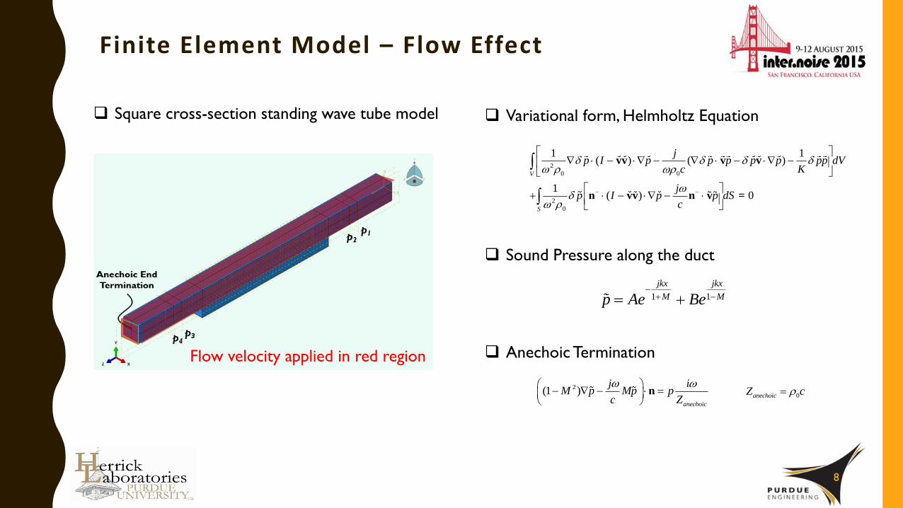
Finite Element Model – Flow Effect
8
Square cross-section standing wave tube model
2
0 0
2
0
1 1( ) ( )
1( ) 0
vv v v
n vv n v =
V
S
jp I p p p p p pp dV
c K
jp I p p dS
c
Variational form, Helmholtz Equation
Flow velocity applied in red region
Sound Pressure along the duct
1 1
jkx jkx
M Mp Ae Be
Anechoic Termination
2(1 ) nanechoic
j iM p Mp p
c Z
0anechoicZ c

TL Results Comparison
9
0 500 1000 1500 2000 25000
1
2
3
4
5
6
7
8
9
Frequency [Hz]
(a)
TL [
dB
]
0 500 1000 1500 2000 25000
1
2
3
4
5
6
7
8
9
Frequency [Hz]
(b)
TL [
dB
]
No MPP without mean flow (Measurement)
No MPP with mean flow, 8.5 m/s (Measurement)
No MPP without mean flow (Prediction)
No MPP with mean flow, 8.5 m/s (Prediction)
0 500 1000 1500 2000 25000
1
2
3
4
5
6
7
8
9
Frequency [Hz]
(a)
TL [
dB
]
0 500 1000 1500 2000 25000
1
2
3
4
5
6
7
8
9
Frequency [Hz]
(b)
TL [
dB
]
MPP549 without no flow fem (Prediction)
MPP549 with mean flow, 8.5 m/s (Prediction)
MPP 549 without mean flow (Measurement)
MPP 549 with mean flow, 8.5 m/s (Measurement)
Measurement Prediction
Mean Flow
P1 P2 P3 P4
No Mean Flow
P1 P2 P3 P4
MPP lining attached
Mean Flow
P1 P2 P3 P4
No Mean Flow
P1 P2 P3 P4
No MPP lining

Flow effects in the TL of the muffler
10
The prototype muffler used in this study Muffler attached to the standing wave tube
Two end terminations
Load 1 Load II
Dimension [cm]
lt 9.60
do 15.2
di 2.90
Flow velocity
21.6 m/s, M = 0.063

Comparison Results – Single chamber muffler
11
Measurement VS Prediction
Mean Flow
Flow VS No Mean flow
0 1000 2000 3000 4000 5000 60000
5
10
15
20
25
30
35
40
45
50
Frequency [Hz]
TL [
dB
]
Transmission Coefficient
Single chamber, No lining, EXP, No flow
Single chamber, No lining, EXP, Flow velocity: 20m/s
0 1000 2000 3000 4000 5000 60000
5
10
15
20
25
30
35
40
45
50
Frequency [Hz]
TL [
dB
]
Transmission Coefficient
Single chamber, No lining, EXP, Flow velocity: 20m/s
Single chamber, No lining, FEM, Flow velocity: 20m/s
Mean Flow
Measurement:

Comparison Results – Single chamber muffler
12
0 1000 2000 3000 4000 5000 60000
5
10
15
20
25
30
35
40
45
50Transmition Loss
Frequency
TL
Single, MPP454 lining, FEM, Flow velocity 20 m/s
Single, MPP454 lining, EXP, Flow velocity 20 m/s
mpp454
Flow VS No Mean flow
0 1000 2000 3000 4000 5000 60000
5
10
15
20
25
30
35
40
45
50Transmition Loss
Frequency
TL
Single, No lining, EXP, No flow
Single, MPP454 liing,EXP, No Flow
Single, MPP454 lining, EXP, Flow velocity 20 m/s
Measurement VS Prediction
mpp454
Measurement:
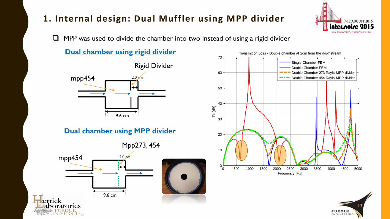
1. Internal design: Dual Muffler using MPP divider
13
2.0 cm
9.6 cm
mpp454
Mpp273, 454
2.0 cm
9.6 cm
mpp454
Rigid Divider
MPP was used to divide the chamber into two instead of using a rigid divider
Dual chamber using MPP divider
Dual chamber using rigid divider
0 500 1000 1500 2000 2500 3000 3500 4000 4500 50000
10
20
30
40
50
60
70Transmition Loss - Double chamber at 2cm from the downstream
Frequency [Hz]
TL [
dB
]
Single Chamber FEM
Double Chamber FEM
0 500 1000 1500 2000 2500 3000 3500 4000 4500 50000
10
20
30
40
50
60
70Transmition Loss - Double chamber at 2cm from the downstream
Frequency [Hz]
TL [
dB
]
Single Chamber FEM
Double Chamber FEM
Double Chamber 273 Rayls MPP divider
Double Chamber 454 Rayls MPP divider

0 1000 2000 3000 4000 5000 60000
5
10
15
20
25
30
35
40
45
50
Frequnecy [Hz]
TL [
dB
]
Transmission Loss
Double MPP454 divider, MPP454 lining, No flow, EXP
Double MPP454 divider, MPP454 lining, No flow, FEM
MPP Dual chamber with MPP lining (No mean flow)
14
2.0 cm
9.6 cm
mpp454MPP 454
No flow
2.0 cm
9.6 cm
mpp454 MPP 454
No flow
Improves minima !!
0 1000 2000 3000 4000 5000 60000
5
10
15
20
25
30
35
40
45
50
Frequency [Hz]
TL [
dB
]
Transmission Loss
Double MPP454 divider, FEM
Double MPP454 divider, EXP

0 1000 2000 3000 4000 5000 60000
5
10
15
20
25
30
35
40
45
50
Frequency [Hz]
TL [
dB
]
Transmission Loss
MPP dual chamber, MPP454lining, EXP, flow: 20m/s
MPP dual chamber, MPP454lining, FEM, flow: 20m/s
MPP Dual chamber with MPP l ining (Mean f low)
15
2.0 cm
9.6 cm
No mean flow Mean flow
0 1000 2000 3000 4000 5000 60000
5
10
15
20
25
30
35
40
45
50
Frequnecy [Hz]
TL [
dB
]Transmission Loss
Double MPP454 divider, MPP454 lining, No flow, EXP
Double MPP454 divider, MPP454 lining, No flow, FEM
Measurement: TL at frequency region below 2500 Hz was affected by flow effect

2. Internal design: Inlet and outlet extension
16
MPP 454
Hole diameter [μm] 103.6
Thickness [mm] 0.35
Flow resistance [Rayls] 454
0 1000 2000 3000 4000 50000
10
20
30
40
50
60
70
80Transmition Loss
Frequency [Hz]
TL [
dB
]
A Type
B Type
C Type
D Type
Lee et al. (NoiseCon 14)
Previous
Suggested
design
Current work with inlet/outlet extensions
0 1000 2000 3000 4000 50000
10
20
30
40
50
60
70
80Transmition Loss
Frequency [Hz]
TL [
dB
]
A Type
B Type
C Type
D Type
Lee et al. (NoiseCon 14)
0 1000 2000 3000 4000 50000
10
20
30
40
50
60
70
80Transmition Loss
Frequency [Hz]
TL [
dB
]
A Type
B Type
C Type
D Type
Lee et al. (NoiseCon 14)
0 1000 2000 3000 4000 50000
10
20
30
40
50
60
70
80Transmition Loss
Frequency [Hz]
TL [
dB
]
A Type
B Type
C Type
D Type
Lee et al. (NoiseCon 14)
0 1000 2000 3000 4000 50000
10
20
30
40
50
60
70
80Transmition Loss
Frequency [Hz]
TL [
dB
]
A Type
B Type
C Type
D Type
Lee et al. (NoiseCon 14)

Type C muffler with flow effects
17
0 1000 2000 3000 4000 5000 60000
10
20
30
40
50
60
Frequency [Hz]
TL [
dB
]
Transmission loss
C Type, FEM, no mean flow
C Type, EXP, no mean flow
0 1000 2000 3000 4000 5000 60000
10
20
30
40
50
60
Frequency [Hz]
TL [
dB
]
Transmission loss
C Type, FEM, flow velocity: 20m/s
C Type, EXP, flow velocity: 20m/s
C4.5 cm 2.0 cm
9.6 cm
Type C muffler with No mean flow effect
Measurement VS PredictionType C muffler with Mean flow effect
Measurement VS Prediction
NO significant difference in TL at this mean flow velocity with low Mach number

Comparison results (Type C vs MPP dual chamber)
18
0 1000 2000 3000 4000 5000 60000
5
10
15
20
25
30
35
40
45
50
Frequency [Hz]
TL [
dB
]
Transmission Loss
C Type, EXP, no mean flow
C Type, EXP, flow velocity: 20m/s
MPP dual chamber, MPP454 lining, EXP, No flow
MPP dual chamber, MPP454lining, EXP, flow: 20m/s
4.5 cm 2.0 cm
9.6 cm
2.0 cm
9.6 cm
MPP 454
Type C Muffler
MPP dual chamber muffler
VS.

Conclusion and Future work
19
Design of acoustic silencers that attenuate noise efficiently over the speech interference range
were suggested by FEM and verified experimentally.
Internal structure designs such as inlet/outlet extensions and MPP divided chambers were
considered.
Mean flow effects in the muffler were considered and it was found that the mean flow with
relatively low Mach number did not affect the acoustic performance of the mufflers of suggested
designs significantly.
More optimized internal designs of the muffler will be considered in the future.
Different combinations of inlet and outlet extension lengths combining with MPP lining.
Multi-layer linings will be considered in multi-chamber mufflers.