design of an abort gap monitor for the large hadron collider · january 7, 2005 larp note 1 cbp...
TRANSCRIPT
January 7, 2005 LARP Note 1CBP Tech Note - 329
1
Design of an Abort Gap Monitor for the LargeHadron Collider†
J.-F. Beche*, J. Byrd*, S. De Santis*, P. Denes*, M. Placidi*,
R. Thurman-Keup#, W. Turner*, M. Zolotorev*
*Lawrence Berkeley National Laboratory, Berkeley, USA#Fermi National Laboratory, Batavia, USA
Abstract. We present a study of an abort gap monitor for the Large Hadron Collider. This is a
critical instrument in the machine protection chain and high-accuracy specifications have been laid
out for it. We briefly discuss the different options for designing the monitor and present
experimental results obtained using what we believe is the most suitable technique, based on a
photomultiplier with a gated microchannel plate.
INTRODUCTION
The Large Hadron Collider rings are characterized by an enormous amount of stored
energy (350 MJ/beam), so that special care has to be taken in avoiding accidental beamlosses [1]. A beam dumping system, capable of handling such high energies, has been
designed, with its fast kickers placed near IR6 for steering the beam into the high-power
dump block. A 3.3 µs long gap along the machine, corresponding to the abort kickers’
rise time, has to be kept free of charges. This is generally referred to as the abort gap.Any particle present in the abort gap at the time of the kickers’ firing would not receive
the proper kick and would therefore hit machine components.
The maximum tolerable proton densities in the gap, under the level expected to causequenches in the superconducting magnets, are reported in [2] for injection and nominal
†Work supported by the U.S. Department of Energy under contract DE-AC03-76SF00098.
January 7, 2005 LARP Note 1CBP Tech Note - 329
2
energies. The thresholds at intermediate energies can be obtained by interpolation and areanyway less important since the machine operates at those energies for the limited
amount of time during the ramping.
Various considerations suggest subdividing the abort gap length into 100 ns longintervals, so that the threshold charge densities are 6·106 p/100 ns and 4·109 p/100 ns at 7
TeV and 450 GeV respectively.There are different mechanisms leading to accumulation of charges in the abort gap.
Injection timing errors produce an instantaneous accumulation of charges above the
maximum threshold, even in the case of the pilot bunch used for pre-injection testing. Inthis scenario, it is sufficient to detect this circumstance before the following injection
batch, which takes place some 20 s later.Diffusion processes and capture of unbunched beam can also cause the abort gap to
become populated and the time scales associated to these phenomena go from around 1 s
to tens of seconds [3]. Based on these considerations, the maximum integration time formonitoring the abort gap has been set to 100 ms.
TECHNOLOGIES FOR MONITORING THE ABORT GAP
There are a number of methods that one can use in principle for detecting the presence of
charges in the LHC abort gap. We can group them in two categories, depending onwhether they detect the wake-field associated to such charges, or measure the emitted
synchrotron radiation. Whichever the chosen method might be, it is required to have a
fast response time, to be able to monitor the first empty RF buckets in the gap, followingthe bunch train. These buckets are the first to fill due to intrabunch diffusion and are the
most difficult to monitor being next to high-current bunches.
Wake-field based methodsBeam current monitors (BCM), fast current transformers (FCT) and beam position
monitors (BPM) could, in principle, be used for monitoring the abort gap. All thesedevices can be designed with a bandwidth large enough to be able to discriminate single
bunches. They also have the intrinsic advantage to be already included in the LHC
January 7, 2005 LARP Note 1CBP Tech Note - 329
3
design, for other uses, so that there is no need to build and install a separate component,though this would certainly be advisable as the Abort Gap Monitor is to be part of the
machine protection system.
The main disadvantage with using the devices mentioned above is that they do not havethe necessary high signal-to-noise ratio, when the bandwidth is of the order of 1 GHz or
higher. The threshold charge at 7 TeV has a peak current of less than 10 µA and we have
to be able to discriminate from the last filled bunch which has a peak current 106 timeshigher.
It is possible to rapidly gain switch a FCT to prevent saturation from the bunch train, but
this has been realized only at slower speeds than those we would require [4, 5].
Synchrotron light based methodsThe presence of particles in the abort gap can also be detected by observing thesynchrotron light they emit. In the LHC there is a synchrotron light port, designed for a
transverse profile monitor. A possible mirror configuration for longitudinal
measurements, that doesn’t interfere with the transverse diagnostics and that could beused for monitoring the abort gap, has been studied in [6]. There are a variety of
instruments that can be used to measure the synchrotron light; again, like in the wake-
field case, we need the necessary time response properties and sensitivity. In addition thenumber of photons available depends on the particular machine energy. We focus on the
injection and nominal energies of 450 GeV and 7 TeV respectively, has the machine willbe operating at those two energies for most of the time. Performance at intermediate
energies during the ramp can be derived by interpolation.
January 7, 2005 LARP Note 1CBP Tech Note - 329
4
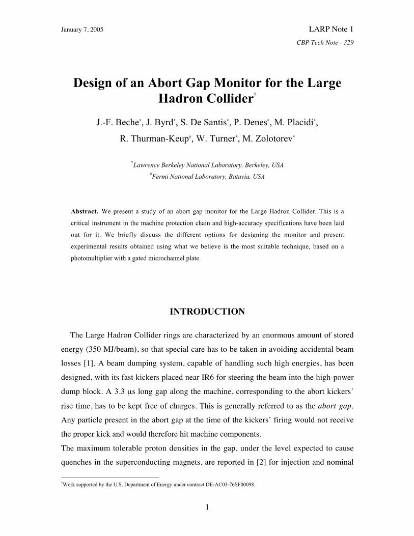
Fig.1 Photon flux from nominal bunches at the synchrotron light diagnostic port. (M.
Facchini)
Figure 1 shows the calculated photon fluxes at various energies. There is a number of
devices one can use to detect this synchrotron radiation: streak camera, photomultipliers(PMT), avalanche photodiodes (APD). All these devices are commonly used for
measuring the beam’s longitudinal distribution and have the time resolution andsensitivity necessary for the application under investigation here.
The streak camera main disadvantage is in the long time lag between data samples;
typical repetition rates are of the order of 1 Hz. A single sample can cover the entire abortgap, but the repetition rate is below specifications.
APD’s have very good quantum efficiency, but their typical dark current levels are 50 to100 times higher than in PMT’s. The main problem with using APD’s for gap monitoring
is their relatively slow gating speed and recovery time, which would effectively create a
blind spot in the first part of the abort gap. This part is actually the most likely to becomefilled by charges diffusing from the last bunches of the train, so that we identified in a

January 7, 2005 LARP Note 1CBP Tech Note - 329
5
gateable microchannel-plate PMT (MCP-PMT) the device of choice for abort gapmonitoring.
MONITORING THE LHC ABORT GAP WITH AN MCP-PMT
Commercially available MCP-PMTs [7] are the ideal instrument for such a task due totheir high gain, fast gate, low noise and variety of peak wavelength of their spectral
response. Also the low voltage required for gating and their reduced dimensions (Fig.2)
are other beneficial features that make the use of such a device particularly simple.
Figure 2. Hamamatsu gateable microchannel-plate photomultiplier R5916U-50 Series.
The minimum gate width for our Hamamatsu R5916U-50 MCP-PMT is 5 ns, with a gaterise time of 1 ns. These numbers are entirely suitable for use in the LHC, where the
sampling window is 100 ns and the distance between RF bucket is 2.5 ns, so that it is
possible to gate out filled buckets nearby the abort gap.Time resolution for the measurement is dominated by the device’s transit time spread
(which can be estimated as equal to the instrument response function). Figure 3 showsthat for our device that is roughly equal to 100 ps, again well below our resolution
requirements. The response decreases by 3 orders of magnitude in 1 ns, which is
substantially shorter than the 2.5 ns bucket separation in the LHC.

January 7, 2005 LARP Note 1CBP Tech Note - 329
6
Figure 3. Instrument Response Function for the R5916U-50 MCP-PMT.
The main parameters for the Hamamatsu tube are summarized in Tab.1. Given the device
maximum duty factor of 1%, different strategies are possible for mapping the abort gap.
The most immediate one is using a 100 ns gate width, which allows for taking onemeasurement every turn.
Gate rise time: 1 ns
Gate length: 5 ns ÷ 10 µs
Max duty cycle: 1%Gate voltage: 10 V
Max. gain: 106
Output rise time: 180 psTransit time spread: 90 ps
Dark counts: 10 cps
Table 1. MCP-PMT specifications (Hamamatsu R5916U-50)
To cover the entire abort gap 33 such measurements are necessary, with the timing of thegate continuously shifted to move the observation window along the gap. Furthermore,
the 100 ms allowable integration time, as per specification [2], permits to accumulate and
average 34 measurements of each individual sample. From Fig.1 we can calculate the
January 7, 2005 LARP Note 1CBP Tech Note - 329
7
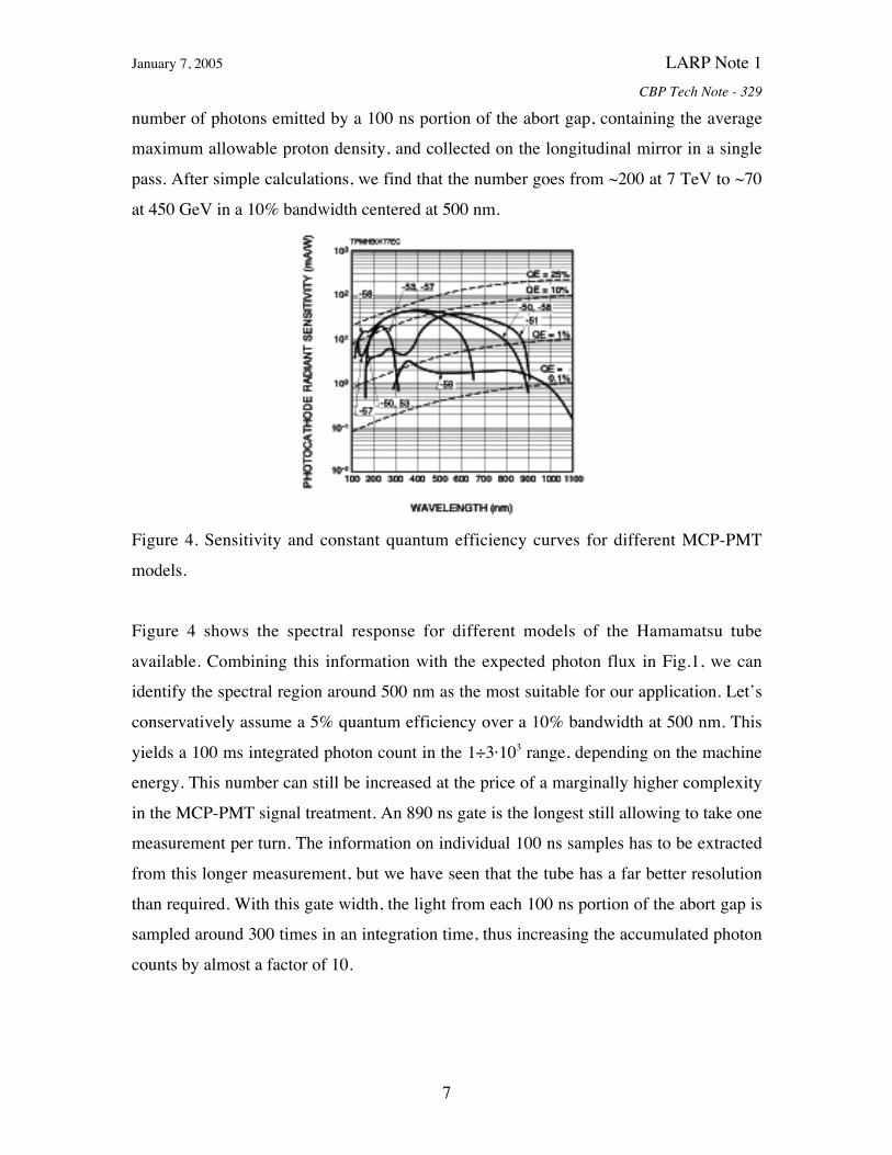
number of photons emitted by a 100 ns portion of the abort gap, containing the averagemaximum allowable proton density, and collected on the longitudinal mirror in a single
pass. After simple calculations, we find that the number goes from ~200 at 7 TeV to ~70
at 450 GeV in a 10% bandwidth centered at 500 nm.
Figure 4. Sensitivity and constant quantum efficiency curves for different MCP-PMT
models.
Figure 4 shows the spectral response for different models of the Hamamatsu tube
available. Combining this information with the expected photon flux in Fig.1, we canidentify the spectral region around 500 nm as the most suitable for our application. Let’s
conservatively assume a 5% quantum efficiency over a 10% bandwidth at 500 nm. This
yields a 100 ms integrated photon count in the 1÷3·103 range, depending on the machineenergy. This number can still be increased at the price of a marginally higher complexity
in the MCP-PMT signal treatment. An 890 ns gate is the longest still allowing to take onemeasurement per turn. The information on individual 100 ns samples has to be extracted
from this longer measurement, but we have seen that the tube has a far better resolution
than required. With this gate width, the light from each 100 ns portion of the abort gap issampled around 300 times in an integration time, thus increasing the accumulated photon
counts by almost a factor of 10.

January 7, 2005 LARP Note 1CBP Tech Note - 329
8
EXPERIMENTAL RESULTS AT THE ALS AND TEVATRON
We conducted a series of experiments both at the Advanced Light Source and at theTevatron, using our Hamamatsu tube to detect synchrotron radiation. The results obtained
so far prove how much a MCP-PMT based abort gap monitor would be suitable for
application to the LHC.
LHC ALS TEVATRON
Revolution time (Trev) 88.9 µs 657 ns 21 µs
Bunch length (στ) 620 ps 30 ps 1600 ps
Gap length (G τ) 3.39 µs 120 ns 3 x 2.4 µs
Bunch charge (qb) 18 nC 0.9÷6.5 nC 53 nC
RF buckets spacing 2.5 ns 2 ns 19 ns
Table 2. Beam parameters for LHC, ALS and Tevatron
ALS experimentsSeveral parameters of the ALS storage ring (Tab.2) make it a good place for testing apossible utilization of a MCP-PMT as an abort gap monitor for the LHC: similar distance
between RF buckets and a gap length equal to the length of an LHC sample. The ALSring also features a special high current bunch (referred to as camshaft) in the middle of
its fill gap which is followed by very low current parasitic bunches, due to diffusion of
electrons from the camshaft into the following RF buckets. This is particularly interestingfrom the point of view of studying eventual saturation phenomena in the MCP-PMT,
which could interfere with the detection of a low charge density next to a much larger
one.Our experimental station is at the ALS diagnostic beamline (BL 3.1) which uses the
synchrotron radiation generated in a bending dipole (1.3 T).

January 7, 2005 LARP Note 1CBP Tech Note - 329
9
Figure 5. Block diagram of the experimental setup at the ALS.
Figure 5 shows the block diagram of our experimental setup at BL 3.1. The 10 V gatingpulse, synchronized to the ring orbit clock (SROC), can be shifted around using a delay
box and the internal pulser capabilities.
Figure 6. The 104 ns long ALS fill gap with camshaft.
Figure 6 shows an image of the entire ALS fill gap. Four regularly filled bunches can beseen at the beginning and at the end of the gap and the camshaft is the larger signal
between them. This picture was obtained setting the oscilloscope on an infinite
persistence time, so that we are indeed observing data accumulated over a very largenumber of turns.
January 7, 2005 LARP Note 1CBP Tech Note - 329
10
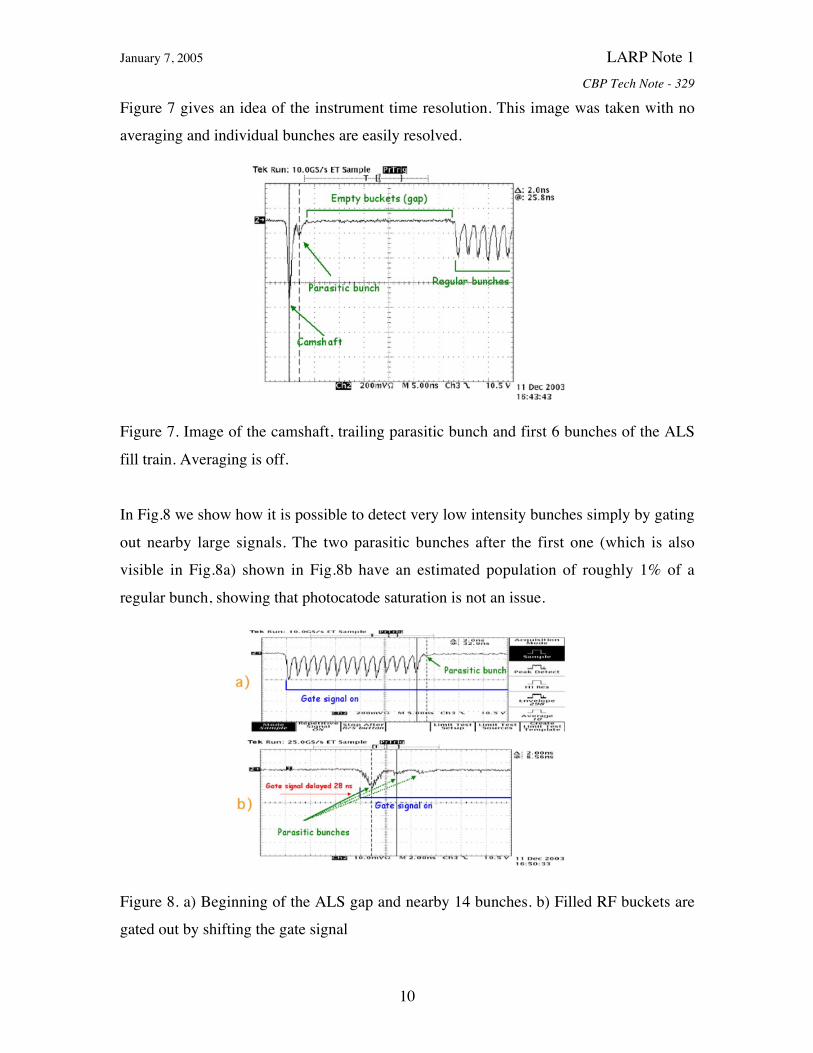
Figure 7 gives an idea of the instrument time resolution. This image was taken with noaveraging and individual bunches are easily resolved.
Figure 7. Image of the camshaft, trailing parasitic bunch and first 6 bunches of the ALS
fill train. Averaging is off.
In Fig.8 we show how it is possible to detect very low intensity bunches simply by gating
out nearby large signals. The two parasitic bunches after the first one (which is alsovisible in Fig.8a) shown in Fig.8b have an estimated population of roughly 1% of a
regular bunch, showing that photocatode saturation is not an issue.
Figure 8. a) Beginning of the ALS gap and nearby 14 bunches. b) Filled RF buckets aregated out by shifting the gate signal
January 7, 2005 LARP Note 1CBP Tech Note - 329
11
Furthermore, a comparison of signal base levels with gate on and off shows the very low
noise characteristics of the instrument and the absence of dark counts.
Tevatron experimentsWe also conducted tests at the Tevatron. In this case we wanted to use the MCP-PMT in
photon-counting mode to verify its performance with a reduced photon flux. We alsowanted to measure synchrotron radiation emitted by unbunched beam (which can
possibly be present in proton rings) and check how hard it is to separate that signal from
the measurement background. Our experimental setup was similar to the one used at theALS (Fig.5), with minor differences to allow operating in single-photon counting mode
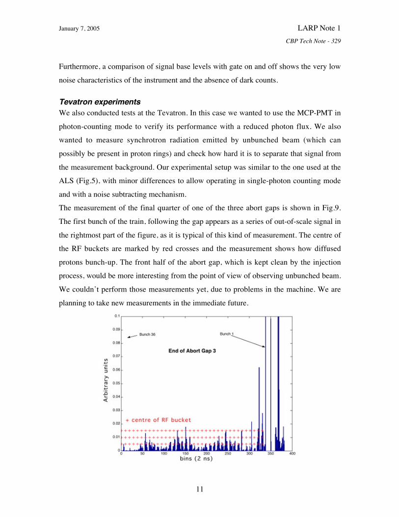
and with a noise subtracting mechanism.The measurement of the final quarter of one of the three abort gaps is shown in Fig.9.
The first bunch of the train, following the gap appears as a series of out-of-scale signal in
the rightmost part of the figure, as it is typical of this kind of measurement. The centre ofthe RF buckets are marked by red crosses and the measurement shows how diffused
protons bunch-up. The front half of the abort gap, which is kept clean by the injectionprocess, would be more interesting from the point of view of observing unbunched beam.
We couldn’t perform those measurements yet, due to problems in the machine. We are
planning to take new measurements in the immediate future.

January 7, 2005 LARP Note 1CBP Tech Note - 329
12
Figure 9. 800 ns sample of the Tevatron abort gap and first filled bucket.
Bench measurementsWe also performed bench measurements to test the instrument’s response at the photonfluxes expected in the LHC. We used an optical power meter, bandpass filters and
diaphragms to obtain a light intensity equal to what calculated for the LHC in thebandwidth we want to operate our abort gap monitor (Fig.10). The MCP-PMT gate is
enabled for 100 ns, which is likely the gate length to be used in the LHC and the gate
signal repetition rate is also chosen accordingly to what would be used in practice.
Figure 10. Experimental setup for sensitivity measurements.
Figures 11 and 12 show the results for a number of photons corresponding to the number
emitted in 100 ns by a uniform charge distribution with total charge equal to the threshold
value for the abort gap monitor.
January 7, 2005 LARP Note 1CBP Tech Note - 329
13
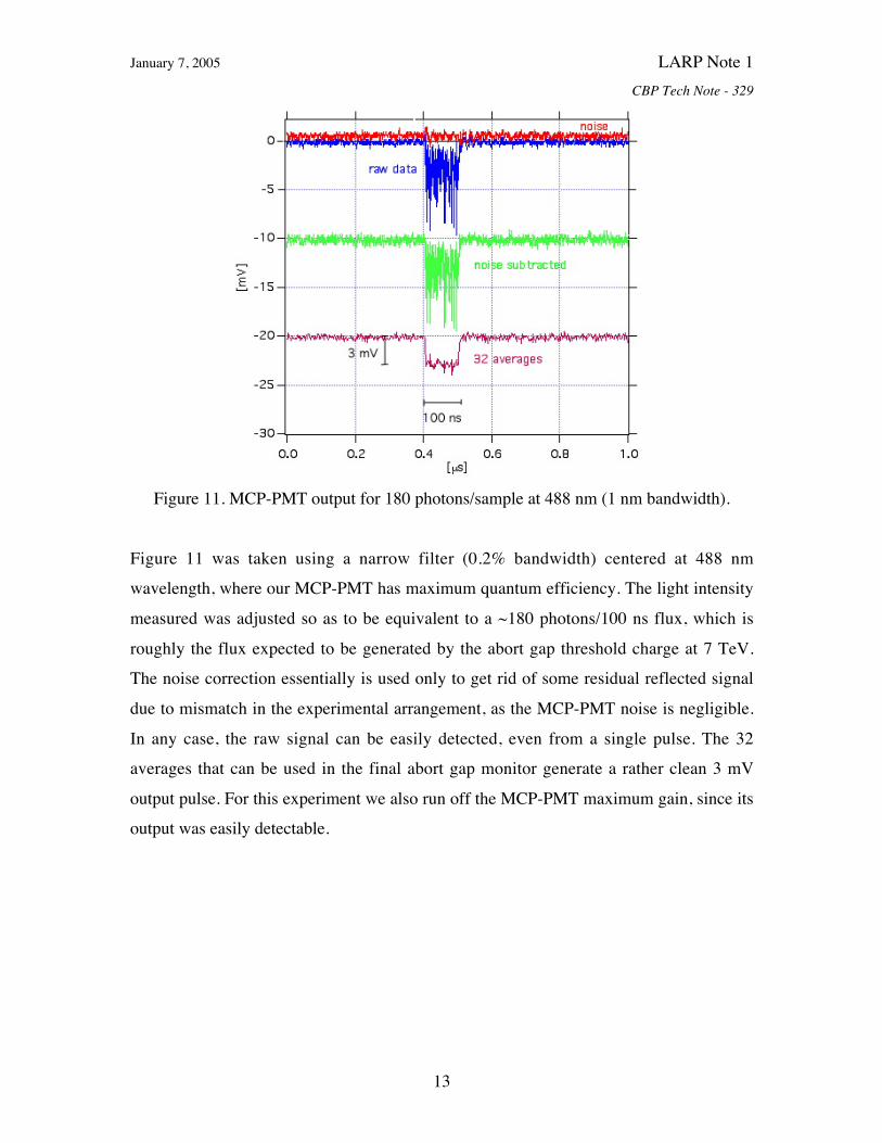
Figure 11. MCP-PMT output for 180 photons/sample at 488 nm (1 nm bandwidth).
Figure 11 was taken using a narrow filter (0.2% bandwidth) centered at 488 nmwavelength, where our MCP-PMT has maximum quantum efficiency. The light intensity
measured was adjusted so as to be equivalent to a ~180 photons/100 ns flux, which is
roughly the flux expected to be generated by the abort gap threshold charge at 7 TeV.The noise correction essentially is used only to get rid of some residual reflected signal
due to mismatch in the experimental arrangement, as the MCP-PMT noise is negligible.
In any case, the raw signal can be easily detected, even from a single pulse. The 32averages that can be used in the final abort gap monitor generate a rather clean 3 mV
output pulse. For this experiment we also run off the MCP-PMT maximum gain, since itsoutput was easily detectable.

January 7, 2005 LARP Note 1CBP Tech Note - 329
14
Figure 12. MCP-PMT output for 50 photons/sample at 600 nm (70 nm bandwidth).
In Fig.12 we show a similar measurement for the photon flux expected at 450 GeV. Weused a different filter, to test the device on a larger bandwidth, and had to raise the gain to
its maximum. As in the earlier case, the output generate is of the order of a few millivolts
and its detection doesn’t present any particular problem.We also measured the intensity of the synchrotron light available at the ALS and
estimated that the number of photons generated by a single ALS standard bunch isroughly 40÷50 times the threshold at 7 TeV. Consequently the measurements of the
parasitic bunches shown in Figs.7 and 8 is a good exemplification of what would be
required in the LHC.
DATA ACQUISITION
The data acquisition from the MCP-PMT doesn’t present particular difficulties. Aspreviously mentioned, it is sufficient to use a 100 ns long gate on the MCP-PMT; the 100
ms integration time allows to accumulate 33 such measures of the same 100 ns long
portion of the abort gap; the output level is continuously compared to a predeterminedthreshold level and, if necessary, an alarm is generated. Then the gate is shifted by 100 ns
and the process is repeated until the entire abort gap has been mapped.
January 7, 2005 LARP Note 1CBP Tech Note - 329
15
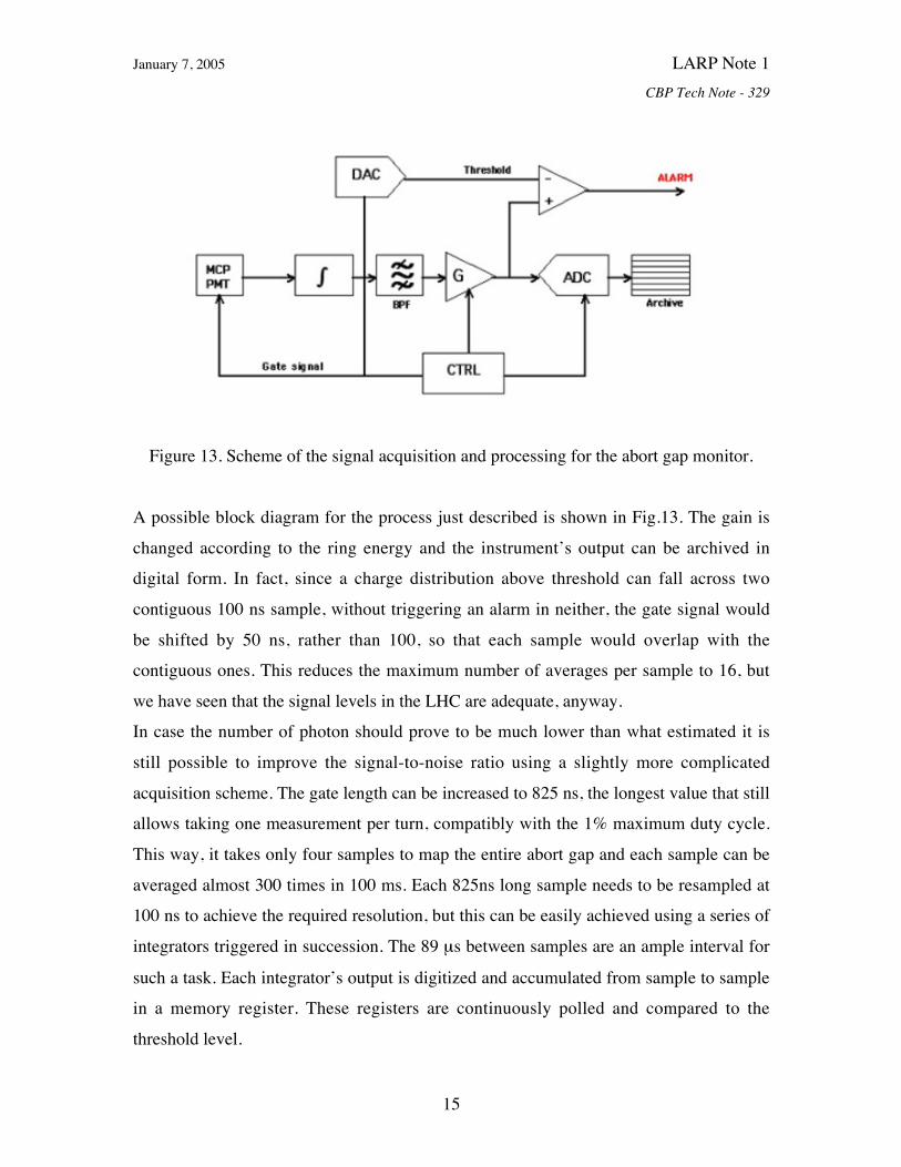
Figure 13. Scheme of the signal acquisition and processing for the abort gap monitor.
A possible block diagram for the process just described is shown in Fig.13. The gain is
changed according to the ring energy and the instrument’s output can be archived indigital form. In fact, since a charge distribution above threshold can fall across two
contiguous 100 ns sample, without triggering an alarm in neither, the gate signal would
be shifted by 50 ns, rather than 100, so that each sample would overlap with thecontiguous ones. This reduces the maximum number of averages per sample to 16, but
we have seen that the signal levels in the LHC are adequate, anyway.In case the number of photon should prove to be much lower than what estimated it is
still possible to improve the signal-to-noise ratio using a slightly more complicated
acquisition scheme. The gate length can be increased to 825 ns, the longest value that stillallows taking one measurement per turn, compatibly with the 1% maximum duty cycle.
This way, it takes only four samples to map the entire abort gap and each sample can be
averaged almost 300 times in 100 ms. Each 825ns long sample needs to be resampled at100 ns to achieve the required resolution, but this can be easily achieved using a series of
integrators triggered in succession. The 89 µs between samples are an ample interval for
such a task. Each integrator’s output is digitized and accumulated from sample to samplein a memory register. These registers are continuously polled and compared to the
threshold level.
January 7, 2005 LARP Note 1CBP Tech Note - 329
16
A calibration for the abort gap monitor can easily be performed at operations start bycirculating a single bunch with the required charge and recording the MCP-PMT output
at various energies.
CONCLUSIONS
We have presented a study on the issues one would encounter in the design of an abort
gap monitor for the Large Hadron Collider. We examined several options and believe that
an instrument based on a gateable micro-channel plate photomultiplier is the mostindicated for the task and can satisfy CERN specifications. We performed experiments
with a Hamamatsu R5916U-50 tube both with beam (ALS and Tevatron) and on thebench. These experiments confirmed the favourable characteristics of the MCP-PMT and
the relative effort required for designing an abort gap monitor around such a device.
REFERENCES
[1] R. Schmidt, “Accidental Beam Losses and Protection in the LHC”, Proc. ICFA-HB
2004 , (2004).[2] C. Fischer, “High Sensitivity Measurement of the Longitudinal Distribution of the
LHC Beams”, LHC-B-ES-0005,(2003).
[3] E. Shaposhnikova, S. Fartoukh and B. Jenneret, “LHC Abort Gap Filling by ProtonBeam”, Proc. EPAC 2004, 211, (2004).
[4] R. Witkove, P. Cameron, T. Shea, R. Connolly and M. Kesselman, “Beam
Instrumentation for the Spallation Neutron Source Ring”, Proc. PAC 1999, 2250,(1999).
[5] http://www.bergoz.com[6] M. Facchini, “Longitudinal Diagnostics Mirror Configuration for the LHC Beam”,
unpublished, (2003).
[7] http://www.hamamatsu.com for example.