design of a tapered and twisted blade for the nrel ... · selection of the most appropriate rotor...
TRANSCRIPT
April 1999 • NREL/SR-500-26173
P. Giguère and M.S. SeligDepartment of Aeronauticaland Astronautical EngineeringUniversity of Illinois at Urbana-ChampaignUrbana, Illinois
Design of a Tapered andTwisted Blade for the NRELCombined Experiment Rotor
March 1998 – March 1999

April 1999 • NREL/SR-500-26173
Design of a Tapered andTwisted Blade for the NRELCombined Experiment Rotor
March 1998 – March 1999
P. Giguère and M.S. SeligDepartment of Aeronauticaland Astronautical EngineeringUniversity of Illinois at Urbana-ChampaignUrbana, Illinois
NREL Technical Monitors: James L. Tangler andDavid A. SimmsPrepared under Subcontract No. XAF-4-14076-03

NOTICE
This report was prepared as an account of work sponsored by an agency of the United States government.Neither the United States government nor any agency thereof, nor any of their employees, makes anywarranty, express or implied, or assumes any legal liability or responsibility for the accuracy, completeness,or usefulness of any information, apparatus, product, or process disclosed, or represents that its use wouldnot infringe privately owned rights. Reference herein to any specific commercial product, process, or serviceby trade name, trademark, manufacturer, or otherwise does not necessarily constitute or imply itsendorsement, recommendation, or favoring by the United States government or any agency thereof. Theviews and opinions of authors expressed herein do not necessarily state or reflect those of the United Statesgovernment or any agency thereof.
Available to DOE and DOE contractors from:Office of Scientific and Technical Information (OSTI)P.O. Box 62Oak Ridge, TN 37831
Prices available by calling 423-576-8401
Available to the public from:National Technical Information Service (NTIS)U.S. Department of Commerce5285 Port Royal RoadSpringfield, VA 22161703-605-6000 or 800-553-6847orDOE Information Bridgehttp://www.doe.gov/bridge/home.html
Printed on paper containing at least 50% wastepaper, including 20% postconsumer waste

iii
ForewordPrevious phases of experimenting with the Combined Experiment Rotor (CER) of the NationalRenewable Energy Laboratory (NREL) have provided test results from two constant-chord blade sets.The first blade set had no twist whereas the second had twist. As the next step, the design of atapered/twisted blade for the CER was contracted out to the Department of Aeronautical andAstronautical Engineering of the University of Illinois at Urbana-Champaign. This blade design workconsisted of a systematic trade-off study where many blade configurations were compared to determinehow much the design constraints affected blade performance. Based on the results of the tradeoff study, ablade having a linear taper and nonlinear twist, and that uses the S809 airfoil, was selected as the newCER blade. An extended version of this blade was also designed for a two-bladed rotor configuration.The new CER blades are presently being built by an independent blade manufacturer. NREL plans to testthe new blades under constant- and variable-speed operations.
______________________James L. TanglerNational Renewable Energy Laboratory – National Wind Technology Center1617 Cole Boulevard.Golden, Colorado 80401 USAE-mail: [email protected]: 303-384-6934Fax: 303-384-6901

iv
PrefaceA tapered/twisted blade set was designed for the Combined Experiment Rotor (CER) of the NationalRenewable Energy Laboratory. The objective was to build on the knowledge base of the previous CERtests conducted with constant-chord/untwisted blades and constant-chord/twisted blades. Such CERtapered/twisted blades will yield performance that is more representative of commercial blades. Inaddition, these new blades will continue to satisfy the scientific needs for fundamental research in rotoraerodynamics.
This blade design work for the CER was performed during the summer of 1997 while the first author wasat the National Wind Technology Center. The authors would like to thank NREL for providing fundingunder subcontract XAF-4-14076-03 and the opportunity to design new blades for the CER. Also, theauthors would like to thank James L. Tangler, David A. Simms, and Lee J. Fingersh of NREL for theirfeedback and suggestions throughout this blade design work. The comments of Dr. Michael C. Robinsonand C.P. (Sandy) Butterfield of NREL were also appreciated.
v
SummaryA tapered/twisted blade was designed to operate on the Combined Experiment Rotor (CER) of theNational Renewable Energy Laboratory (NREL), which is a stall-regulated downwind wind turbinehaving a rated power of 20 kilowatt. The geometry of the new blade set was optimized based on annualenergy production subject to the constraints imposed on the design. These constraints were mainlyrelated to scientific needs for fundamental research in rotor aerodynamics. A trade-off study wasconducted to determine the effect of the different design constraints. Based on the results of this study,which considered nonlinear twist and taper distributions as well as the NREL S809, S814, S822 and S823airfoils, a blade having a linear taper and a nonlinear twist distribution that uses the S809 airfoil from rootto tip was selected. This blade configuration is the logical continuation of the previous constant-chordtwisted and untwisted blade sets and will facilitate comparison with those earlier blades. Despite thedesign constraints based on scientific needs, the new blade is more representative of commercial bladesthan the previous blade sets.
The new blade was designed to be applicable for three- and two-bladed rotor configurations. To enhancethe performance of the new blade in a two-bladed rotor configuration instead of the baseline three-bladedrotor, an increase in blade span was investigated, which led to the design of an extended blade having a10% increase in span. Furthermore, an increase in rotor speed was also investigated. A two-bladed rotormaking use of extended blades and rotating at a speed 8% faster than the baseline speed or revolution perminute setting was found to yield comparable power output to that of the new blades in a three-bladedrotor configuration. Results for the CER equipped with the new blades (baseline and extended blades) interms of mechanical power output, rotor thrust as well as lift coefficient and axial inflow distributionsalong the blade span are presented. Even though the new blades were designed for constant-speedoperations, they can also be used for fundamental research in variable-speed operations. To facilitate theselection of the most appropriate rotor configuration for the NREL variable-speed test bed using the newblades, results showing the power coefficient as a function of the tip-speed ratio for various pitch settingsare presented. Finally, recommendations for future blade sets for the CER are also given.

vi
ContentsForeword……………………………………………………………………………………………….… iii
Preface………………………………………………………………………………………………….…iv
Summary……………………………………………………………………………………………….… v
Nomenclature...…………………………..…………………………………………………………….… vii
Introduction…………………………………………………………………………..………….…..…... 1
Design Constraints…………………………………………………………….………………..………... 2
Design Approach…………………………………………………………….…………………...……….3
Design Trade-offs and Blade Geometry Optimization……………...……….……………………..……. 4
Performance Predictions………………………………………………….….………………………..…. 8
Conclusions and Recommendations………………………………………….……………………….…. 14
References…………………………………………………………….……………………..….………...15
Appendix A: Tabulated Data for the Tapered/Twisted CER blade……………..………………….……. 16
Appendix B: Tabulated Results for Figures 4-8...……………………….……………………….……… 17
vii
List of Figures1. Planform of the baseline tapered/twisted CER blade (three-bladed rotor configuration)………….. 6
2. Planform of the extended tapered/twisted CER blade (two-bladed rotor configuration)…………... 6
3. Final twist distribution of the tapered/twisted CER blade...………………………………………….7
4. Power curves for the tapered/twisted CER blade...………………………………………………….. 8
5. Rotor thrust curves for the tapered/twisted CER blade...……………………………………………. 9
6. Lift coefficient distribution along the span for the tapered/twisted CER blade...…………………… 10
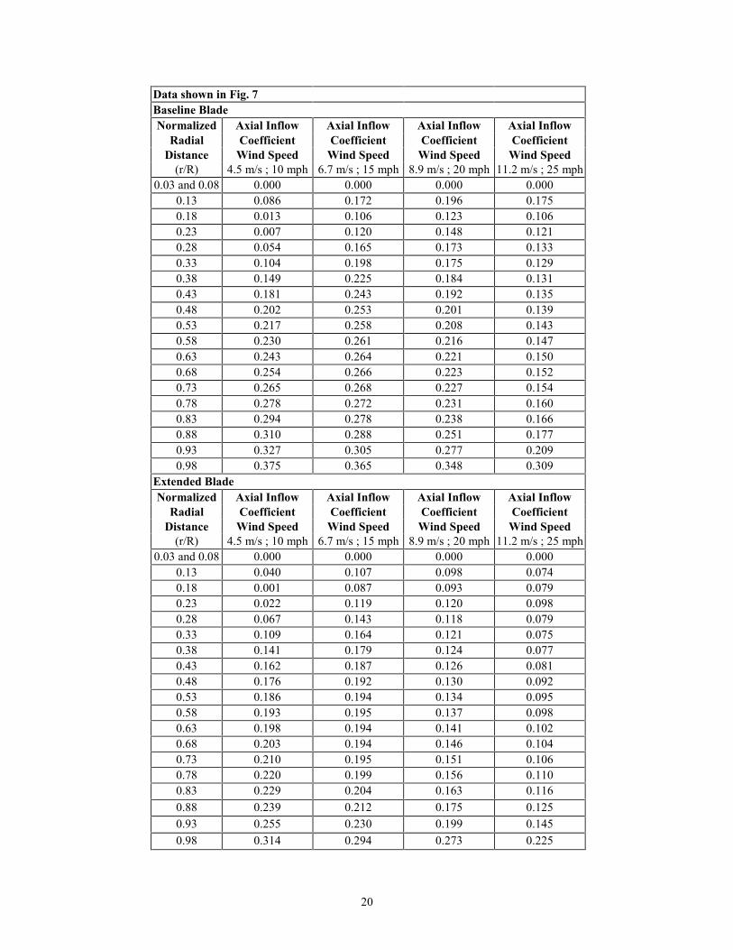
7. Axial inflow coefficient distribution along the span for the tapered/twisted CER blade...…………..11
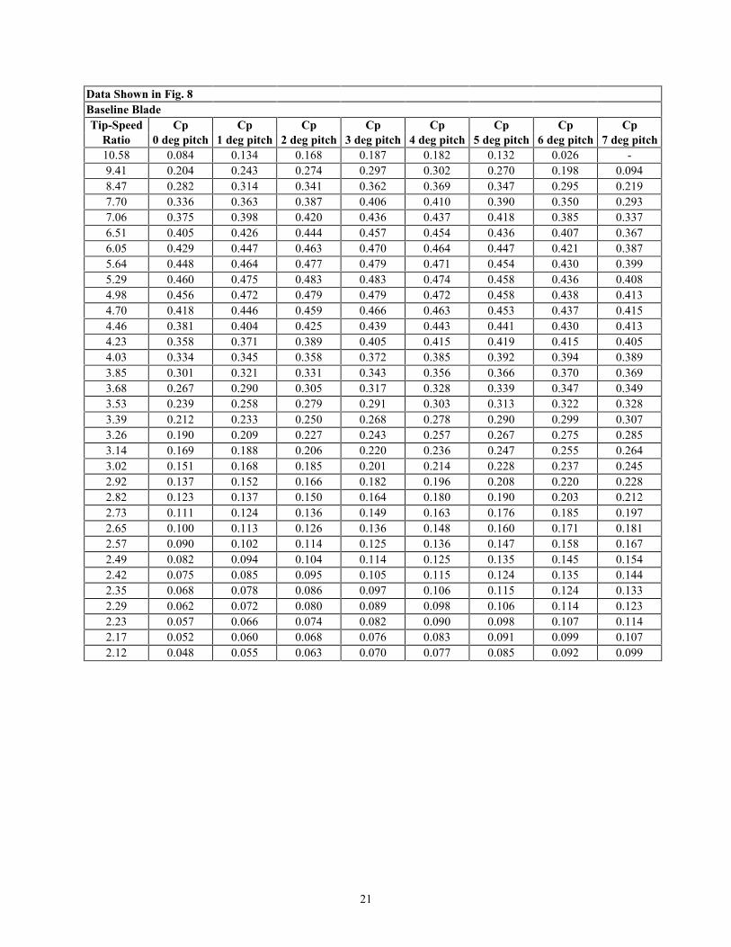
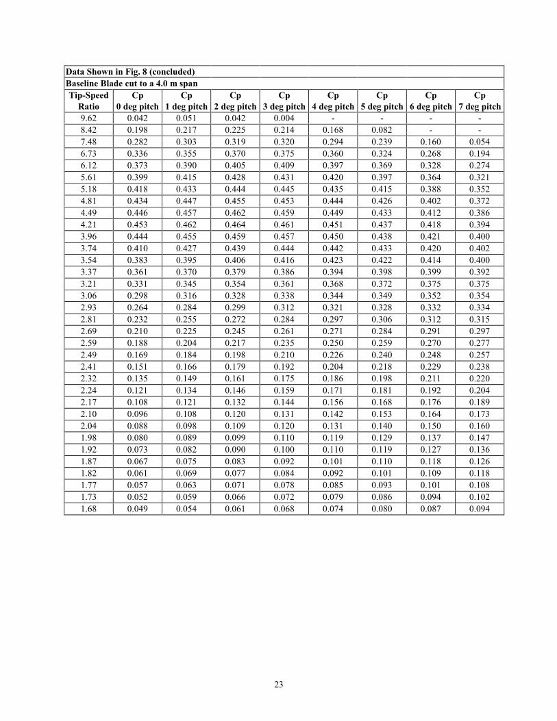
8. Power coefficient vs. tip-speed ratio for the tapered/twisted CER blade...…………………………..12
List of Tables1. Results of the blade configuration trade-off study…………………………………………………... 5
Nomenclature
c Blade chord
HD Hub diameter
R Blade radius
r Radial distance along the blade span from the center of the rotor
N Newton

1
IntroductionThe Combined Experiment Rotor (CER) of the National Renewable Energy Laboratory (NREL) has adiameter of 10.06 m (33 ft) and is composed of three blades. This rotor is mounted on a Grumman WindStream 33 horizontal axis wind turbine (HAWT), which is a stall-regulated downwind machine having arated power of 20 kilowatt (kW) and operating at a speed of 72 revolutions per minute (rpm).1 To date,two blade sets were tested with this wind turbine for fundamental research in rotor aerodynamics. Thefirst blade set was composed of constant-chord/untwisted blades and the second set had constant-chord/twisted blades. Both of these blade sets were built with a chord of 457 mm (18 in.) and used theNREL S809 airfoil along the entire span. In addition, one blade of each set was instrumented withchordwise pressure taps and a 5-hole probe at five spanwise locations, namely at 30%, 47%, 63%, 80%,and 95% span. These two blade sets were extensively tested and the results of those experiments can befound in Refs. 2 and 3.
The objective of this work was to design a third blade set for the CER having both taper and twist. Incontrast with the two other blade sets, the blade geometry for the new set was to be designed formaximum annual energy production. Because of the need for fundamental research in rotoraerodynamics and practical aspects, constraints were imposed on the design. An important part of thiswork was to conduct a study of the design trade-offs to determine the effect of those constraints on theenergy capture of the rotor. Another objective was to determine the necessary modifications to the bladegeometry and operating rpm for a two-bladed rotor configuration. This report describes the approach andprocess used to design a tapered/twisted blade, and provides performance predictions for the CERequipped with the new blades. The performance of the CER equipped with the new blade set was alsoinvestigated under variable-speed operation.

2
Design ConstraintsNREL provided the design constraints for the tapered/twisted CER blades.4 Some practical constraintswere imposed to facilitate the instrumentation of the new blades in a manner similar to the previous CERblade sets. Other constraints were imposed to ensure consistency with the previous blade sets for ease ofcomparison of the data. The design constraints for the tapered/twisted blades for the CER were asfollows:
• A blade span of 5.03 m (16.5 ft) including a 102-mm (4-in.) tip shape for the baseline three-bladed rotor• A rated power of 20 kW• A cone angle of 3.4 degrees• Keep distance from pitch axis to the leading edge less than 584 mm (23 in.) so that the 5-hole probes do
not hit the tower• A minimum chord of 305 mm (12 in.) to allow for the installation of pressure taps and instrumentation
on the instrumented blade• A fixed chord length of 457 mm (18 in.) at 80% of the blade span for comparison of the pressure data
with the previous blade sets• Use the S8095 airfoil for as much of the blade span as possible to facilitate comparison with the
previous blade sets• Transition to the S8145 root airfoil from the S809 airfoil not to begin before 47% of the blade span.

3
Design ApproachThe computer programs PROPID6,7 and PROPGA7,8 were used to carry out the blade design process.PROPID is an inverse design and analysis method for HAWTs that is based on the blade-element/momentum theory PROP code.9 The inverse design capabilities of PROPID allow for the desiredperformance and aerodynamic characteristics of the rotor to be prescribed from which the blade geometryand corresponding operating conditions are determined. In the present design work, the inverse designcapability of PROPID was used to limit the mechanical power output of the CER to 20 kW. Also, thePrandtl tip-loss model was used and the Corrigan post-stall model10 was incorporated into PROPID tomodify the two-dimensional airfoil for three-dimensional effects.11 PROPGA is a genetic algorithmbased optimization method for HAWTs that relies on PROPID for the analysis of the possible blade/rotordesigns. Given a set of design constraints/requirements, bounds for the parameters to be optimized, and afigure of merit (objective function) for the optimization, PROPGA provides the optimum blade geometry.
As a first and important step in the design process, the trade-offs between various blade configurationsand airfoils were investigated to determine the effect of the design constraints on the energy capture of therotor. For each blade configuration considered, the blade geometry was optimized for maximum grossannual energy production (GAEP) using PROPGA. Once the final blade geometry was selected,PROPID was used to finalize the blade twist distribution and pitch setting. Particular attention was givento obtaining smooth stall characteristics along the entire blade span. Following the design of the bladesfor the baseline three-bladed rotor, PROPID was also used to determine the necessary modifications to theblade geometry and operating rotor speed for a two-bladed rotor configuration. In addition, PROPID wasused to provide performance predictions with greater accuracy under constant-speed and variable-speedoperations.
Throughout the design process, the GAEP (assuming a 100% generator efficiency) was computed basedon a Rayleigh wind-speed distribution having an average wind speed of 7.2 m/s (16 mph), which isrepresentative of the windy months at NREL. Also, the power output of the rotor was computed up to awind speed of 17.9 m/s (40 mph) using standard atmospheric conditions at the altitude of the NationalWind Technology Center (1,829 m or 6,000 ft). The number of segments used along the blade span was10 for a PROPGA run and 20 when using PROPID outside the optimization scheme of PROPGA. Inpredicting rotor performance, airfoil data obtained from wind tunnel experiments over a range ofReynolds numbers were used. To interpolate between Reynolds numbers, a logarithmic scheme was usedfor the drag and linear interpolation was used for the lift. Similar schemes were also used when necessaryto extrapolate the data above the largest Reynolds number in the available data.

4
Design Trade-offs and Blade Geometry OptimizationThe trade-off study was subdivided into a number of tasks that were defined by NREL.4 The first twotasks were to optimize blades without any of the design constraints to provide a basis for comparison.The chord and twist distributions as well as the blade pitch were optimized for three sets of NRELairfoils:5
• S809 from root to tip• S814 at the root (0%–35% span) and S809 at the tip (75%–100% span)• S823 at the root (0%–35% span) and S822 at the tip (75%–100% span).
For the two cases with multiple airfoils along the blade span, a linear transition was used between the twoairfoils. The case with the S822 and S823 airfoils was added to the NREL task list because of theobjective to maximize energy capture. These two airfoils were designed for small blades, and thus havedesign Reynolds numbers that are closer to the operating range of the CER as compared with the S809and S814 airfoils, which were designed for medium-size wind turbines. It is important to note, however,that the S822 and S823 airfoils were designed after the first blade set for the CER was designed and built.The selection of the S809 airfoil was initially based on the need to use a well-documented airfoil and atthe time of the design of the first blade set for the CER, the S809 airfoil had been extensively tested at theDelft wind tunnel.12 For the second blade set, the S809 airfoil was used for consistency to provide a basisfor comparison with the first blade set. The S814 airfoil was also tested in the Delft wind tunnel at a latertime.13 The airfoil data gathered with the S809 and S814 were used in the blade optimization process.For the S822 and S823 airfoils, the data used were obtained from the University of Illinois at Urbana-Champaign low-turbulence subsonic wind tunnel.14,15 The data sets for each airfoil used in the designprocess were for clean-surface conditions. Note that the data below a Reynolds number of 1,000,000 forthe S809 airfoil, and below 700,000 for the S814 airfoil, were obtained from logarithmic extrapolationsfor the drag and linear extrapolations for the lift.
The results of the trade-off study are summarized in Table 1. The blades optimized without any chordand twist constraints using the S809 airfoil with or without the S814 root airfoil provided equivalentenergy capture, which was about 3% less than the GAEP of the blade making use of the S822 and S823airfoils. This 3% increase in GAEP by using the S822 and S823 airfoils was not judged to be significantenough to offset the desire to preserve consistency with the S809 airfoil for the new CER blades. Athicker airfoil inboard having a higher maximum lift coefficient would, of course, provide a blade designmore representative of commercial blades. Therefore, the S814 airfoil was further considered in thedesign.
Among the three blades optimized without any constraints, all had tip-chord lengths larger than 305 mm(12 in.). Therefore, the minimum chord constraint did not cause a loss in performance. It was found thatconstraining the blade to a linear taper was not significantly detrimental to the energy capture as long asthe twist distribution was nonlinear. Consequently, a linear taper was adopted. The constraint that hadthe most significant negative impact on the energy capture was the 457-mm (18-in.) chord lengthconstraint at 80% blade span, which resulted in a loss in energy capture that ranged from 2.5% to 7%depending on the tip chord. For a given set of constraints, the optimized blades that made use of the S814airfoil inboard provided slightly better energy capture than blades using only the S809 airfoil.
Because of the importance of the 457-mm (18-in.) chord constraint at 80% of the blade span forcomparison of pressure data with the existing blade sets, the planform of the new blades was designedaround that constraint. Consequently, the design of the blade planform was oriented towards a more"scientific" blade rather than a "commercial" blade. Nevertheless, the new blades are more representativeof commercial blades than the previous two blade sets. According to the selection of a planform based onscientific needs, it seemed logical to design the blades with only the S809 airfoil. Apart from the ease of
5
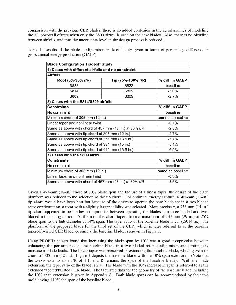
comparison with the previous CER blades, there is no added confusion in the aerodynamics of modelingthe 3D post-stall effects when only the S809 airfoil is used on the new blades. Also, there is no blendingbetween airfoils, and thus the uncertainty level in the design process is reduced.
Table 1: Results of the blade configuration trade-off study given in terms of percentage difference ingross annual energy production (GAEP)
Blade Configuration Tradeoff Study1) Cases with different airfoils and no constraintAirfoils
Root (0%-30% r/R) Tip (75%-100% r/R) % diff. in GAEPS823 S822 baselineS814 S809 -3.0%S809 S809 -2.7%
2) Cases with the S814/S809 airfoilsConstraints % diff. in GAEPNo constraint baselineMinimum chord of 305 mm (12 in.) same as baselineLinear taper and nonlinear twist -0.1%Same as above with chord of 457 mm (18 in.) at 80% r/R -2.5%Same as above with tip chord of 305 mm (12 in.) -2.7%Same as above with tip chord of 356 mm (13.5 in.) -3.7%Same as above with tip chord of 381 mm (15 in.) -5.1%Same as above with tip chord of 419 mm (16.5 in.) -6.9%3) Cases with the S809 airfoilConstraints % diff. in GAEPNo constraint baselineMinimum chord of 305 mm (12 in.) same as baselineLinear taper and nonlinear twist -0.3%Same as above with chord of 457 mm (18 in.) at 80% r/R -3.5%
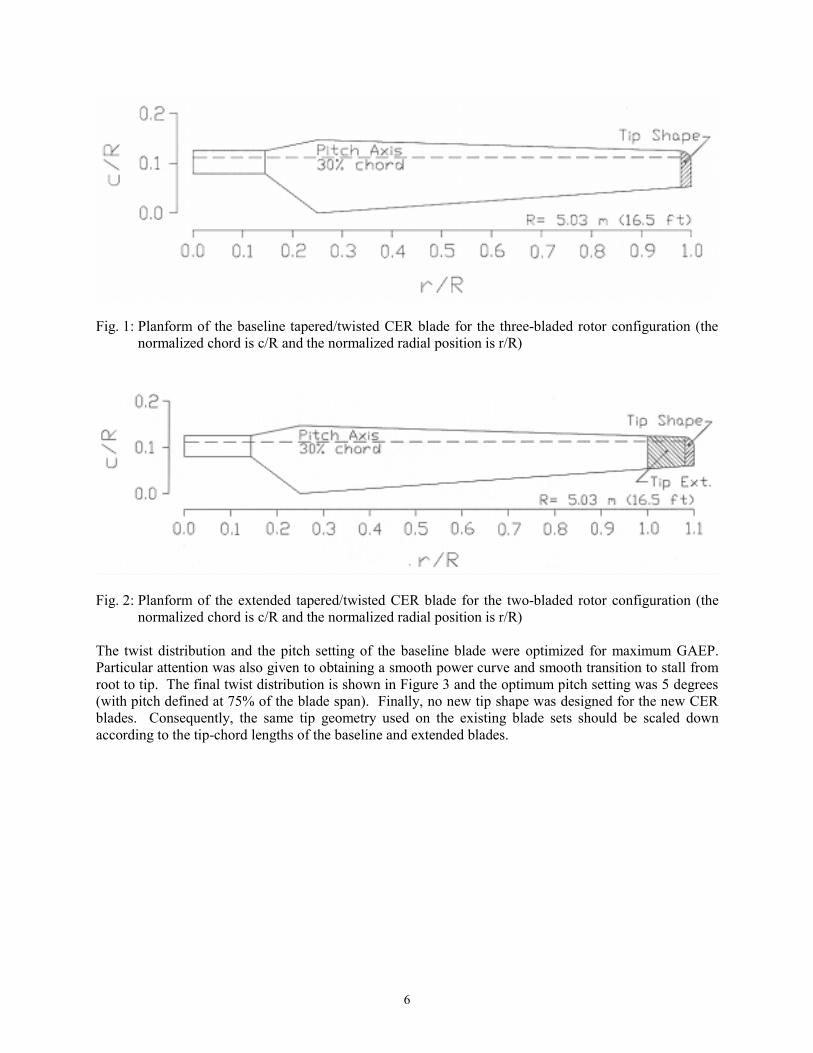
Given a 457-mm (18-in.) chord at 80% blade span and the use of a linear taper, the design of the bladeplanform was reduced to the selection of the tip chord. For optimum energy capture, a 305-mm (12-in.)tip chord would have been best but because of the desire to operate the new blade set in a two-bladedrotor configuration, a rotor with a slightly larger solidity was selected. More precisely, a 356-mm (14-in.)tip chord appeared to be the best compromise between operating the blades in a three-bladed and two-bladed rotor configuration. At the root, the chord tapers from a maximum of 737 mm (29 in.) at 25%blade span to the hub diameter at 14% span. The taper ratio of the baseline blade is 2.1 (29:14 in.). Theplanform of the proposed blade for the third set of the CER, which is later referred to as the baselinetapered/twisted CER blade, or simply the baseline blade, is shown in Figure 1.
Using PROPID, it was found that increasing the blade span by 10% was a good compromise betweenenhancing the performance of the baseline blade in a two-bladed rotor configuration and limiting theincrease in blade loads. The linear taper was preserved in extending the baseline blade, which gave a tipchord of 305 mm (12 in.). Figure 2 depicts the baseline blade with the 10% span extension. (Note thatthe x-axis extends to a r/R of 1.1, and R remains the span of the baseline blade). With the bladeextension, the taper ratio of the blade is 2.4. The blade with the 10% increase in span is referred to as theextended tapered/twisted CER blade. The tabulated data for the geometry of the baseline blade includingthe 10% span extension is given in Appendix A. Both blade spans can be accommodated by the samemold having 110% the span of the baseline blade.
6
Fig. 1: Planform of the baseline tapered/twisted CER blade for the three-bladed rotor configuration (thenormalized chord is c/R and the normalized radial position is r/R)
Fig. 2: Planform of the extended tapered/twisted CER blade for the two-bladed rotor configuration (thenormalized chord is c/R and the normalized radial position is r/R)
The twist distribution and the pitch setting of the baseline blade were optimized for maximum GAEP.Particular attention was also given to obtaining a smooth power curve and smooth transition to stall fromroot to tip. The final twist distribution is shown in Figure 3 and the optimum pitch setting was 5 degrees(with pitch defined at 75% of the blade span). Finally, no new tip shape was designed for the new CERblades. Consequently, the same tip geometry used on the existing blade sets should be scaled downaccording to the tip-chord lengths of the baseline and extended blades.

7
Fig.3: Final twist distribution of the tapered/twisted CER blade with pitch defined at 75% span of thebaseline blade (the normalized chord is c/R and the normalized radial position is r/R)
8
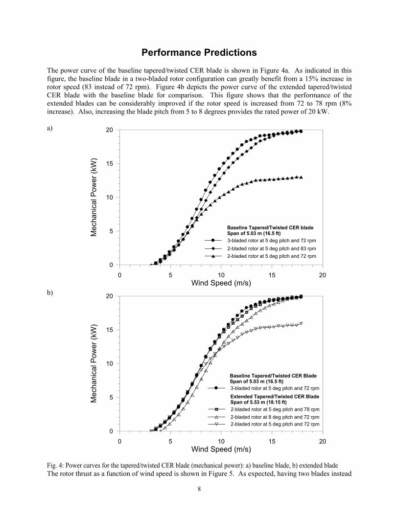
Performance PredictionsThe power curve of the baseline tapered/twisted CER blade is shown in Figure 4a. As indicated in thisfigure, the baseline blade in a two-bladed rotor configuration can greatly benefit from a 15% increase inrotor speed (83 instead of 72 rpm). Figure 4b depicts the power curve of the extended tapered/twistedCER blade with the baseline blade for comparison. This figure shows that the performance of theextended blades can be considerably improved if the rotor speed is increased from 72 to 78 rpm (8%increase). Also, increasing the blade pitch from 5 to 8 degrees provides the rated power of 20 kW.
a)
b)
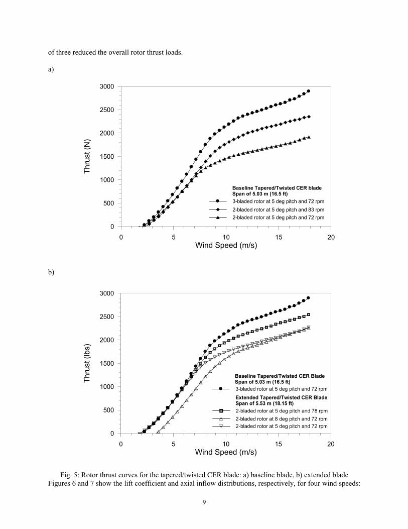
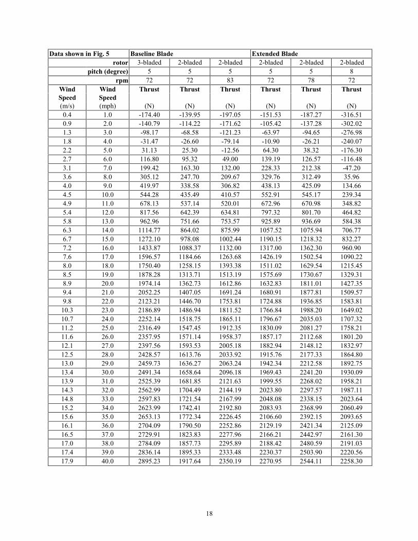
Fig. 4: Power curves for the tapered/twisted CER blade (mechanical power): a) baseline blade, b) extended bladeThe rotor thrust as a function of wind speed is shown in Figure 5. As expected, having two blades instead
3-bladed rotor at 5 deg pitch and 72 rpm
2-bladed rotor at 5 deg pitch and 72 rpm2-bladed rotor at 5 deg pitch and 83 rpm
Baseline Tapered/Twisted CER bladeSpan of 5.03 m (16.5 ft)
0 5 10 15 20Wind Speed (m/s)
0
5
10
15
20
Mec
hani
cal P
ower
(kW
)
3-bladed rotor at 5 deg pitch and 72 rpm
2-bladed rotor at 5 deg pitch and 72 rpm
2-bladed rotor at 5 deg pitch and 78 rpm2-bladed rotor at 8 deg pitch and 72 rpm
Extended Tapered/Twisted CER BladeSpan of 5.53 m (18.15 ft)
Baseline Tapered/Twisted CER BladeSpan of 5.03 m (16.5 ft)
0
5
10
15
20
Mec
hani
cal P
ower
(kW
)
0 5 10 15 20Wind Speed (m/s)
9
of three reduced the overall rotor thrust loads.
a)
b)
Fig. 5: Rotor thrust curves for the tapered/twisted CER blade: a) baseline blade, b) extended bladeFigures 6 and 7 show the lift coefficient and axial inflow distributions, respectively, for four wind speeds:
3-bladed rotor at 5 deg pitch and 72 rpm
2-bladed rotor at 5 deg pitch and 72 rpm2-bladed rotor at 5 deg pitch and 83 rpm
Baseline Tapered/Twisted CER bladeSpan of 5.03 m (16.5 ft)
0
500
1000
1500
2000
2500
3000Th
rust
(N)
0 5 10 15 20Wind Speed (m/s)
3-bladed rotor at 5 deg pitch and 72 rpm
2-bladed rotor at 5 deg pitch and 72 rpm
2-bladed rotor at 5 deg pitch and 78 rpm2-bladed rotor at 8 deg pitch and 72 rpm
Extended Tapered/Twisted CER BladeSpan of 5.53 m (18.15 ft)
Baseline Tapered/Twisted CER BladeSpan of 5.03 m (16.5 ft)
0 5 10 15 20Wind Speed (m/s)
0
500
1000
1500
2000
2500
3000
Thru
st (l
bs)

10
4.5, 6.7, 9.0, and 11.2 m/s (10, 15, 20, and 25 mph). Note that the inboard drop in lift coefficient shownin Figure 6b for a wind speed of 11.2 m/s (25 mph) indicates that the blade is stalled over that portion ofthe blade. The axial inflow distribution not being at the optimum value of one third is an indication thatthe new CER blades are not truly optimized for maximum energy capture. Also, the lower values of theaxial induction coefficient for the extended blade for a given wind speed and radial position along theblade span, accounts for the lower thrust of the two-bladed rotor configuration.
a)
b)
Fig. 6: Lift coefficient distribution along the span for the tapered/twisted CER blade: a) baseline blade, b)extended blade
0.0 0.1 0.2 0.3 0.4 0.5 0.6 0.7 0.8 0.9 1.0Normalized Distance Along Blade Span (r/R)
0.0
0.5
1.0
1.5
Lift
Coe
ffici
ent
4.5 m/s (10 mph)6.7 m/s (15 mph)9.0 m/s (20 mph)11.2 m/s (25 mph)
Baseline Tapered/Twisted CER BladeSpan of 5.03 m (16.5 ft)3-bladed rotor at pitch of 5 deg and 72 rpm
0.0 0.1 0.2 0.3 0.4 0.5 0.6 0.7 0.8 0.9 1.0Normalized Distance Along Blade Span (r/R)
0.0
0.5
1.0
1.5
Lift
Coe
ffici
ent
4.5 m/s (10 mph)6.7 m/s (15 mph)9.0 m/s (20 mph)11.2 m/s (25 mph)
Extended Tapered/Twisted CER BladeSpan of 5.53 m (18.2 ft)2-bladed rotor at pitch of 5 deg and 72 rpm

11
a)
b)
Fig. 7: Axial inflow coefficient distribution along the span for the tapered/twisted CER blade: a) baselineblade, b) extended blade
0.0 0.1 0.2 0.3 0.4 0.5 0.6 0.7 0.8 0.9 1.0Normalized Distance Along Blade Span (r/R)
0.0
0.1
0.2
0.3
0.4
0.5
Axia
l Inf
low
Coe
ffici
ent
4.5 m/s (10 mph)6.7 m/s (15 mph)9.0 m/s (20 mph)11.2 m/s (25 mph)
Baseline Tapered/Twisted CER BladeSpan of 5.03 m (16.5 ft)3-bladed rotor at pitch of 5 deg and 72 rpm
0.0 0.1 0.2 0.3 0.4 0.5 0.6 0.7 0.8 0.9 1.0Normalized Distance Along Blade Span (r/R)
0.0
0.1
0.2
0.3
0.4
0.5
Axia
l Inf
low
Coe
ffici
ent
4.5 m/s (10 mph)6.7 m/s (15 mph)9.0 m/s (20 mph)11.2 m/s (25 mph)
Extended Tapered/Twisted CER BladeSpan of 5.53 m (18.2 ft)2-bladed rotor at pitch of 5 deg and 72 rpm
12
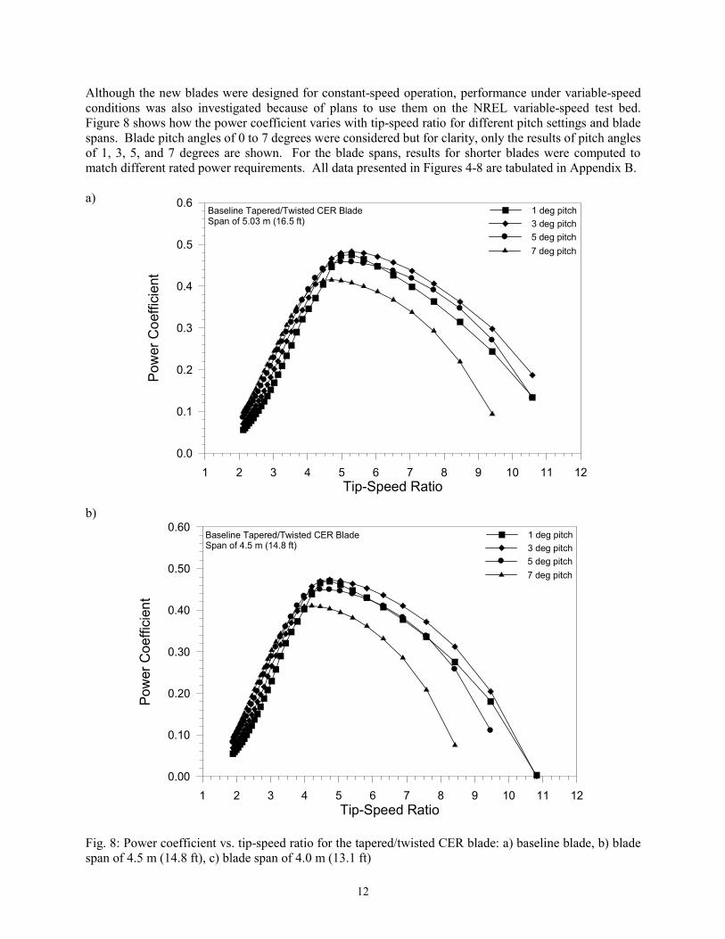
Although the new blades were designed for constant-speed operation, performance under variable-speedconditions was also investigated because of plans to use them on the NREL variable-speed test bed.Figure 8 shows how the power coefficient varies with tip-speed ratio for different pitch settings and bladespans. Blade pitch angles of 0 to 7 degrees were considered but for clarity, only the results of pitch anglesof 1, 3, 5, and 7 degrees are shown. For the blade spans, results for shorter blades were computed tomatch different rated power requirements. All data presented in Figures 4-8 are tabulated in Appendix B.
a)
b)
Fig. 8: Power coefficient vs. tip-speed ratio for the tapered/twisted CER blade: a) baseline blade, b) bladespan of 4.5 m (14.8 ft), c) blade span of 4.0 m (13.1 ft)
1 2 3 4 5 6 7 8 9 10 11 12Tip-Speed Ratio
0.0
0.1
0.2
0.3
0.4
0.5
0.6
Pow
er C
oeffi
cien
t
Baseline Tapered/Twisted CER BladeSpan of 5.03 m (16.5 ft)
1 deg pitch3 deg pitch5 deg pitch7 deg pitch
1 2 3 4 5 6 7 8 9 10 11 12Tip-Speed Ratio
0.00
0.10
0.20
0.30
0.40
0.50
0.60
Pow
er C
oeffi
cien
t
Baseline Tapered/Twisted CER BladeSpan of 4.5 m (14.8 ft)
1 deg pitch3 deg pitch5 deg pitch7 deg pitch

13
c)
Fig. 8 (concluded)
1 2 3 4 5 6 7 8 9 10 11 12Tip-Speed Ratio
0.00
0.10
0.20
0.30
0.40
0.50
0.60
Pow
er C
oeffi
cien
t
Baseline Tapered/Twisted CER BladeSpan of 4.0 m (13.1 ft)
1 deg pitch3 deg pitch5 deg pitch7 deg pitch
14
Conclusions and RecommendationsA third blade set for the CER was designed based on an extensive trade-off study that was conducted todetermine the effect of several design constraints on rotor performance. The results of this study led tothe design of a blade having a linear taper and a non linear twist distribution that makes use of the S809airfoil from root to tip. This blade configuration is the logical continuation of the previous blade sets andwill facilitate comparison with those earlier blades. Even though the new blades were designed withmany constraints based on scientific needs, the new blades are more representative of commercial bladesthan the previous blades. The new blades were designed to be applicable for three- and two-bladed rotorconfigurations. To enhance performance in a two-bladed rotor configuration, extending the blade span by10% and increasing the rotor speed from 72 to 78 rpm were found to be beneficial. In fabricating theblades, it is recommended to use a mold with a length of 110% of the span of the baseline blade toaccommodate both the baseline and extended blades. Although the new blades were designed forconstant-speed operations, they can also be applicable for fundamental research in variable-speedoperations. In the event that a fourth blade set for the CER would be built with the goal of designing ablade representative of commercial blades, the use of a more suitable root airfoil is stronglyrecommended. In this respect the S823/S822 airfoil combination would provide enhanced energy captureas compared with the S814/S809 combination.
15
References1Huyer, S.A., Simms, D., and Robinson, M.C., “Unsteady Aerodynamics Associated with a
Horizontal-Axis Wind Turbine,” AIAA Journal, Vol. 34, No. 7, 1996, pp. 1410−1419.2Butterfield, C.P., Musial, W.P., and Simms, D.A., “Combined Experiment Phase I, Final Report,”
NREL/TP-257-4655, October 1996.3Miller, M.S., Shipley, D.E., Young, T.S., Robinson, M.C., and Luttges, M.W., “Combined
Experiment, Phase II Data Characterization,” NREL/TP-442-6916, November 1995.4Simms, D.A., “Design of an Optimized Tapered and Twisted Blade for NREL’s Unsteady
Aerodynamics Experiment Grumman Wind Turbine,” Appendix A of the Statement of Work of NRELSubcontract No. XAF-4-14076-03, September 20, 1996.
5Tangler, J.L. and Somers, D.S., “NREL Airfoil Families for HAWTs,” American Wind EnergyAssociation WindPower ’95 Conference, Washington, DC, 1995.
6Selig, M.S. and Tangler, J.L., “Development and Application of a Multipoint Inverse Design Methodfor Horizontal Axis Wind Turbines,” Wind Engineering, Vol. 19, No. 2, 1995, pp. 91−105.
7Giguère, P. and Selig, M.S., “Aerodynamic Blade Design Methods for Horizontal Axis WindTurbines,” 13th Canadian Wind Energy Association Conference and Exhibition, Quebec City, Quebec,Canada, October 19–22, 1997.
8Selig, M.S. and Coverstone-Carroll, V.L., “Application of a Genetic Algorithm to Wind TurbineDesign,” ASME Journal of Solar Energy Engineering, Vol. 118, March 1996, pp. 22−28.
9Hibb, B. and Radkey, R.L., “Calculating Rotor Performance with the Revised PROP ComputerCode,” Horizontal-Axis Wind System Rotor Performance Model Comparison–A Compendium, WindEnergy Research Center, Rockwell International, Rocky Flats Plant, Golden, CO, RFP-3508, UC-60,1983.
10Corrigan, J.J. and Schilling, J.J., “Empirical Model for Stall Delay Due to Rotation,” AmericanHelicopter Society Aeromechanics Specialists Conference, San Francisco, CA, January 19–21, 1994.
11Tangler, J.L. and Selig, M.S., “An Evaluation of an Empirical Model for Stall Delay Due toRotation for HAWTs,” American Wind Energy Association WindPower ’97 Conference, Austin, TX,1997.
12Somers, D.M., “Design and Experimental Results for the S809 Airfoil,” NREL/SR-440-6918,January 1997 (tests conducted in 1986).
13Somers, D.M., “Design and Experimental Results for the S814 Airfoil,” NREL/SR-440-6919,January 1997 (tests conducted in 1994).
14Selig, M.S., Guglielmo, J.J., Broeren, A.P., and Giguère, P., Summary of Low Speed Airfoil Data–Vol. 1, SoarTech Publications, 1504 N. Horseshoe Circle, Virginia Beach, Virginia 23451, 1995.
15Selig, M.S., Lyon, C.A., Giguère, P, Ninham, C.P., and Guglielmo, J.J., Summary of Low SpeedAirfoil Data–Vol. 2, SoarTech Publications, 1504 N. Horseshoe Circle, Virginia Beach, Virginia 23451,1996.
16
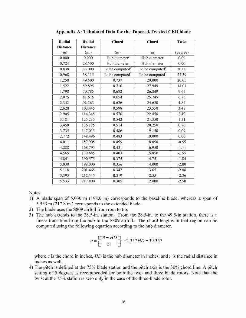
Appendix A: Tabulated Data for the Tapered/Twisted CER blade
Radial Radial Chord Chord TwistDistance Distance
(m) (in.) (m) (in) (degree)0.000 0.000 Hub diameter Hub diameter 0.000.724 28.500 Hub diameter Hub diameter 0.000.838 33.000 To be computed3 To be computed3 30.000.968 38.115 To be computed3 To be computed3 27.591.258 49.500 0.737 29.000 20.051.522 59.895 0.710 27.949 14.041.798 70.785 0.682 26.849 9.672.075 81.675 0.654 25.749 6.752.352 92.565 0.626 24.650 4.842.628 103.445 0.598 23.550 3.482.905 114.345 0.570 22.450 2.403.181 125.235 0.542 21.350 1.513.458 136.125 0.514 20.250 0.763.735 147.015 0.486 19.150 0.092.772 148.496 0.483 19.000 0.004.011 157.905 0.459 18.050 -0.554.288 168.795 0.431 16.950 -1.114.565 179.685 0.403 15.850 -1.554.841 190.575 0.375 14.751 -1.845.030 198.000 0.356 14.000 -2.005.118 201.465 0.347 13.651 -2.085.395 212.335 0.319 12.551 -2.365.533 217.800 0.305 12.000 -2.50
Notes:1) A blade span of 5.030 m (198.0 in) corresponds to the baseline blade, whereas a span of
5.533 m (217.8 in.) corresponds to the extended blade.2) The blade uses the S809 airfoil from root to tip.3) The hub extends to the 28.5-in. station. From the 28.5-in. to the 49.5-in station, there is a
linear transition from the hub to the S809 airfoil. The chord lengths in that region can becomputed using the following equation according to the hub diameter.
where c is the chord in inches, HD is the hub diameter in inches, and r is the radial distance ininches as well.
4) The pitch is defined at the 75% blade station and the pitch axis is the 30% chord line. A pitchsetting of 5 degrees is recommended for both the two- and three-blade rotors. Note that thetwist at the 75% station is zero only in the case of the three-blade rotor.
357.39357.221
29 −+
−= HDrHDc

17
Appendix B: Tabulated Results Figures. 4–8
Data shown in Fig. 4 Baseline Blade Extended Bladerotor 3-bladed 2-bladed 2-bladed 2-bladed 2-bladed 2-bladed
Pitch (degree) 5 5 5 5 5 8rpm 72 72 83 72 78 72
Wind Wind Mechanical Mechanical Mechanical Mechanical Mechanical MechanicalSpeed Speed Power Power Power Power Power Power(m/s) (mph) (kW) (kW) (kW) (kW) (kW) (kW)0.4 1.0 -2.93 -2.17 -3.27 -2.16 -2.62 -6.700.9 2.0 -2.16 -1.62 -2.48 -1.92 -2.36 -4.921.3 3.0 -1.62 -1.40 -2.19 -1.37 -1.72 -3.531.8 4.0 -1.37 -0.98 -1.58 -0.98 -1.47 -2.492.2 5.0 -0.93 -0.65 -1.29 -0.72 -0.98 -1.892.7 6.0 -0.62 -0.39 -0.82 -0.36 -0.67 -1.313.1 7.0 -0.17 -0.03 -0.49 0.02 -0.22 -0.903.6 8.0 0.25 0.32 -0.03 0.42 0.23 -0.484.0 9.0 0.72 0.72 0.42 0.90 0.73 -0.024.5 10.0 1.26 1.19 0.93 1.46 1.32 0.494.9 11.0 1.89 1.72 1.51 2.11 2.00 1.075.4 12.0 2.63 2.34 2.17 2.86 2.77 1.735.8 13.0 3.49 3.06 2.93 3.72 3.66 2.476.3 14.0 4.47 3.87 3.78 4.70 4.67 3.326.7 15.0 5.58 4.77 4.74 5.78 5.80 4.287.2 16.0 6.83 5.74 5.82 6.93 7.05 5.347.6 17.0 8.20 6.69 6.99 8.06 8.38 6.518.0 18.0 9.63 7.53 8.25 9.07 9.73 7.758.5 19.0 11.01 8.24 9.54 9.94 10.98 8.998.9 20.0 12.20 8.89 10.75 10.73 12.08 10.169.4 21.0 13.21 9.50 11.80 11.41 13.03 11.239.8 22.0 14.18 10.00 12.73 11.99 13.94 12.25
10.3 23.0 15.01 10.44 13.60 12.51 14.72 13.2010.7 24.0 15.76 10.83 14.43 12.95 15.37 14.0511.2 25.0 16.48 11.25 15.14 13.41 15.99 14.7511.6 26.0 17.08 11.65 15.74 13.83 16.50 15.3912.1 27.0 17.73 11.97 16.34 14.34 17.03 15.8712.5 28.0 18.24 12.11 16.81 14.60 17.60 16.3813.0 29.0 18.48 12.34 17.33 14.84 18.14 16.8713.4 30.0 18.73 12.56 17.93 15.11 18.50 17.4213.9 31.0 19.06 12.58 18.36 15.25 18.72 17.8614.3 32.0 19.14 12.60 18.60 15.31 19.09 18.2514.8 33.0 19.19 12.68 18.86 15.33 19.47 18.5815.2 34.0 19.31 12.67 19.11 15.39 19.47 18.8515.6 35.0 19.37 12.78 19.41 15.54 19.61 19.0816.1 36.0 19.50 12.81 19.43 15.52 19.62 19.3316.5 37.0 19.59 12.85 19.44 15.67 19.68 19.5317.0 38.0 19.64 12.93 19.52 15.67 19.85 19.6917.4 39.0 19.76 13.02 19.71 15.67 19.82 19.7217.9 40.0 19.78 13.00 19.72 15.91 19.98 20.00
18
Data shown in Fig. 5 Baseline Blade Extended Bladerotor 3-bladed 2-bladed 2-bladed 2-bladed 2-bladed 2-bladed
pitch (degree) 5 5 5 5 5 8rpm 72 72 83 72 78 72
Wind Wind Thrust Thrust Thrust Thrust Thrust ThrustSpeed Speed(m/s) (mph) (N) (N) (N) (N) (N) (N)0.4 1.0 -174.40 -139.95 -197.05 -151.53 -187.27 -316.510.9 2.0 -140.79 -114.22 -171.62 -105.42 -137.28 -302.021.3 3.0 -98.17 -68.58 -121.23 -63.97 -94.65 -276.981.8 4.0 -31.47 -26.60 -79.14 -10.90 -26.21 -240.072.2 5.0 31.13 25.30 -12.56 64.30 38.32 -176.302.7 6.0 116.80 95.32 49.00 139.19 126.57 -116.483.1 7.0 199.42 163.30 132.00 228.33 212.38 -47.203.6 8.0 305.12 247.70 209.67 329.76 312.49 35.964.0 9.0 419.97 338.58 306.82 438.13 425.09 134.664.5 10.0 544.28 435.49 410.57 552.91 545.17 239.344.9 11.0 678.13 537.14 520.01 672.96 670.98 348.825.4 12.0 817.56 642.39 634.81 797.32 801.70 464.825.8 13.0 962.96 751.66 753.57 925.89 936.69 584.386.3 14.0 1114.77 864.02 875.99 1057.52 1075.94 706.776.7 15.0 1272.10 978.08 1002.44 1190.15 1218.32 832.277.2 16.0 1433.87 1088.37 1132.00 1317.00 1362.30 960.907.6 17.0 1596.57 1184.66 1263.68 1426.19 1502.54 1090.228.0 18.0 1750.40 1258.15 1393.38 1511.02 1629.54 1215.458.5 19.0 1878.28 1313.71 1513.19 1575.69 1730.67 1329.318.9 20.0 1974.14 1362.73 1612.86 1632.83 1811.01 1427.359.4 21.0 2052.25 1407.05 1691.24 1680.91 1877.81 1509.579.8 22.0 2123.21 1446.70 1753.81 1724.88 1936.85 1583.81
10.3 23.0 2186.89 1486.94 1811.52 1766.84 1988.20 1649.0210.7 24.0 2252.14 1518.75 1865.11 1796.67 2035.03 1707.3211.2 25.0 2316.49 1547.45 1912.35 1830.09 2081.27 1758.2111.6 26.0 2357.95 1571.14 1958.37 1857.17 2112.68 1801.2012.1 27.0 2397.56 1593.53 2005.18 1882.94 2148.12 1832.9712.5 28.0 2428.57 1613.76 2033.92 1915.76 2177.33 1864.8013.0 29.0 2459.73 1636.27 2063.24 1942.34 2212.58 1892.7513.4 30.0 2491.34 1658.64 2096.18 1969.43 2241.20 1930.0913.9 31.0 2525.39 1681.85 2121.63 1999.55 2268.02 1958.2114.3 32.0 2562.99 1704.49 2144.19 2023.80 2297.57 1987.1114.8 33.0 2597.83 1721.54 2167.99 2048.08 2338.15 2023.6415.2 34.0 2623.99 1742.41 2192.80 2083.93 2368.99 2060.4915.6 35.0 2653.13 1772.34 2226.45 2106.60 2392.15 2093.6516.1 36.0 2704.09 1790.50 2252.86 2129.19 2421.34 2125.0916.5 37.0 2729.91 1823.83 2277.96 2166.21 2442.97 2161.3017.0 38.0 2784.09 1857.73 2295.89 2188.42 2480.59 2191.0317.4 39.0 2836.14 1895.33 2333.48 2230.37 2503.90 2220.5617.9 40.0 2895.23 1917.64 2350.19 2270.95 2544.11 2258.30

19
Data shown in Fig. 6Baseline BladeNormalized Lift Lift Lift Lift
Radial Coefficient Coefficient Coefficient CoefficientDistance Wind Speed Wind Speed Wind Speed Wind Speed
(r/R) 4.5 m/s ; 10 mph 6.7 m/s ; 15 mph 8.9 m/s ; 20 mph 11.2 m/s ; 25 mph0.03 and 0.08 0 0 0 0
0.13 0.2695 0.8077 1.1504 1.22060.18 0.056 0.7449 1.1505 1.23970.23 0.0221 0.6578 1.1342 1.23150.28 0.1352 0.7147 1.1341 1.22830.33 0.2243 0.7774 1.1249 1.21970.38 0.2773 0.7991 1.12 1.21120.43 0.3015 0.7937 1.1098 1.20270.48 0.3077 0.7729 1.1005 1.19380.53 0.3078 0.7488 1.0866 1.18490.58 0.308 0.7281 1.0787 1.17390.63 0.3083 0.7102 1.0651 1.15590.68 0.3093 0.6949 1.0443 1.12750.73 0.3117 0.6825 1.0255 1.09990.78 0.3165 0.6734 1.0062 1.08380.83 0.3224 0.6653 0.9861 1.05370.88 0.3255 0.6512 0.9636 1.020.93 0.3185 0.6193 0.9213 1.01370.98 0.2787 0.5311 0.7986 0.9935
Extended BladeNormalized Lift Lift Lift Lift
Radial Coefficient Coefficient Coefficient CoefficientDistance Wind Speed Wind Speed Wind Speed Wind Speed
(r/R) 4.5 m/s ; 10 mph 6.7 m/s ; 15 mph 8.9 m/s ; 20 mph 11.2 m/s ; 25 mph0.03 and 0.08 0 0 0 0
0.13 0.2376 0.9928 1.2155 1.1390.18 0.007 0.7706 1.137 1.23090.23 0.0838 0.769 1.1348 1.22770.28 0.232 0.8995 1.1711 1.10560.33 0.3292 0.9577 1.186 1.08890.38 0.3774 0.9632 1.1704 1.08950.43 0.3929 0.9401 1.1329 1.10210.48 0.3953 0.9091 1.1114 1.18230.53 0.3939 0.8799 1.0909 1.17220.58 0.39 0.8494 1.0693 1.16240.63 0.3856 0.8197 1.0551 1.1490.68 0.3838 0.795 1.0465 1.12620.73 0.3873 0.7781 1.0399 1.09560.78 0.3936 0.7654 1.0219 1.07520.83 0.3978 0.7504 1.0041 1.05480.88 0.3949 0.7266 0.9823 1.01560.93 0.3812 0.688 0.9512 0.98920.98 0.3356 0.6007 0.8709 0.9955
20
Data shown in Fig. 7Baseline BladeNormalized Axial Inflow Axial Inflow Axial Inflow Axial Inflow
Radial Coefficient Coefficient Coefficient CoefficientDistance Wind Speed Wind Speed Wind Speed Wind Speed
(r/R) 4.5 m/s ; 10 mph 6.7 m/s ; 15 mph 8.9 m/s ; 20 mph 11.2 m/s ; 25 mph0.03 and 0.08 0.000 0.000 0.000 0.000
0.13 0.086 0.172 0.196 0.1750.18 0.013 0.106 0.123 0.1060.23 0.007 0.120 0.148 0.1210.28 0.054 0.165 0.173 0.1330.33 0.104 0.198 0.175 0.1290.38 0.149 0.225 0.184 0.1310.43 0.181 0.243 0.192 0.1350.48 0.202 0.253 0.201 0.1390.53 0.217 0.258 0.208 0.1430.58 0.230 0.261 0.216 0.1470.63 0.243 0.264 0.221 0.1500.68 0.254 0.266 0.223 0.1520.73 0.265 0.268 0.227 0.1540.78 0.278 0.272 0.231 0.1600.83 0.294 0.278 0.238 0.1660.88 0.310 0.288 0.251 0.1770.93 0.327 0.305 0.277 0.2090.98 0.375 0.365 0.348 0.309
Extended BladeNormalized Axial Inflow Axial Inflow Axial Inflow Axial Inflow
Radial Coefficient Coefficient Coefficient CoefficientDistance Wind Speed Wind Speed Wind Speed Wind Speed
(r/R) 4.5 m/s ; 10 mph 6.7 m/s ; 15 mph 8.9 m/s ; 20 mph 11.2 m/s ; 25 mph0.03 and 0.08 0.000 0.000 0.000 0.000
0.13 0.040 0.107 0.098 0.0740.18 0.001 0.087 0.093 0.0790.23 0.022 0.119 0.120 0.0980.28 0.067 0.143 0.118 0.0790.33 0.109 0.164 0.121 0.0750.38 0.141 0.179 0.124 0.0770.43 0.162 0.187 0.126 0.0810.48 0.176 0.192 0.130 0.0920.53 0.186 0.194 0.134 0.0950.58 0.193 0.195 0.137 0.0980.63 0.198 0.194 0.141 0.1020.68 0.203 0.194 0.146 0.1040.73 0.210 0.195 0.151 0.1060.78 0.220 0.199 0.156 0.1100.83 0.229 0.204 0.163 0.1160.88 0.239 0.212 0.175 0.1250.93 0.255 0.230 0.199 0.1450.98 0.314 0.294 0.273 0.225
21
Data Shown in Fig. 8Baseline BladeTip-Speed Cp Cp Cp Cp Cp Cp Cp Cp
Ratio 0 deg pitch 1 deg pitch 2 deg pitch 3 deg pitch 4 deg pitch 5 deg pitch 6 deg pitch 7 deg pitch10.58 0.084 0.134 0.168 0.187 0.182 0.132 0.026 -9.41 0.204 0.243 0.274 0.297 0.302 0.270 0.198 0.0948.47 0.282 0.314 0.341 0.362 0.369 0.347 0.295 0.2197.70 0.336 0.363 0.387 0.406 0.410 0.390 0.350 0.2937.06 0.375 0.398 0.420 0.436 0.437 0.418 0.385 0.3376.51 0.405 0.426 0.444 0.457 0.454 0.436 0.407 0.3676.05 0.429 0.447 0.463 0.470 0.464 0.447 0.421 0.3875.64 0.448 0.464 0.477 0.479 0.471 0.454 0.430 0.3995.29 0.460 0.475 0.483 0.483 0.474 0.458 0.436 0.4084.98 0.456 0.472 0.479 0.479 0.472 0.458 0.438 0.4134.70 0.418 0.446 0.459 0.466 0.463 0.453 0.437 0.4154.46 0.381 0.404 0.425 0.439 0.443 0.441 0.430 0.4134.23 0.358 0.371 0.389 0.405 0.415 0.419 0.415 0.4054.03 0.334 0.345 0.358 0.372 0.385 0.392 0.394 0.3893.85 0.301 0.321 0.331 0.343 0.356 0.366 0.370 0.3693.68 0.267 0.290 0.305 0.317 0.328 0.339 0.347 0.3493.53 0.239 0.258 0.279 0.291 0.303 0.313 0.322 0.3283.39 0.212 0.233 0.250 0.268 0.278 0.290 0.299 0.3073.26 0.190 0.209 0.227 0.243 0.257 0.267 0.275 0.2853.14 0.169 0.188 0.206 0.220 0.236 0.247 0.255 0.2643.02 0.151 0.168 0.185 0.201 0.214 0.228 0.237 0.2452.92 0.137 0.152 0.166 0.182 0.196 0.208 0.220 0.2282.82 0.123 0.137 0.150 0.164 0.180 0.190 0.203 0.2122.73 0.111 0.124 0.136 0.149 0.163 0.176 0.185 0.1972.65 0.100 0.113 0.126 0.136 0.148 0.160 0.171 0.1812.57 0.090 0.102 0.114 0.125 0.136 0.147 0.158 0.1672.49 0.082 0.094 0.104 0.114 0.125 0.135 0.145 0.1542.42 0.075 0.085 0.095 0.105 0.115 0.124 0.135 0.1442.35 0.068 0.078 0.086 0.097 0.106 0.115 0.124 0.1332.29 0.062 0.072 0.080 0.089 0.098 0.106 0.114 0.1232.23 0.057 0.066 0.074 0.082 0.090 0.098 0.107 0.1142.17 0.052 0.060 0.068 0.076 0.083 0.091 0.099 0.1072.12 0.048 0.055 0.063 0.070 0.077 0.085 0.092 0.099

22
Data Shown in Fig. 8 (continued)Baseline Blade cut to a 4.5 m spanTip-Speed Cp Cp Cp Cp Cp Cp Cp Cp
Ratio 0 deg pitch 1 deg pitch 2 deg pitch 3 deg pitch 4 deg pitch 5 deg pitch 6 deg pitch 7 deg pitch10.82 - 0.003 0.014 0.001 0.182 - - -9.47 0.145 0.181 0.199 0.204 0.182 0.110 - -8.42 0.246 0.275 0.298 0.312 0.304 0.258 0.181 0.0757.58 0.311 0.336 0.357 0.372 0.368 0.338 0.284 0.2096.89 0.355 0.377 0.397 0.410 0.406 0.382 0.342 0.2866.31 0.387 0.407 0.425 0.436 0.431 0.410 0.377 0.3325.83 0.412 0.430 0.445 0.453 0.446 0.428 0.399 0.3625.41 0.432 0.447 0.460 0.463 0.456 0.439 0.414 0.3825.05 0.447 0.461 0.471 0.470 0.462 0.446 0.423 0.3954.74 0.457 0.469 0.475 0.473 0.464 0.449 0.429 0.4034.46 0.451 0.465 0.471 0.470 0.463 0.450 0.431 0.4094.21 0.418 0.438 0.451 0.457 0.455 0.445 0.431 0.4113.99 0.386 0.402 0.418 0.429 0.435 0.433 0.424 0.4093.79 0.362 0.373 0.387 0.398 0.406 0.410 0.409 0.4013.61 0.335 0.348 0.359 0.370 0.379 0.384 0.387 0.3843.44 0.301 0.320 0.332 0.343 0.352 0.360 0.363 0.3643.29 0.266 0.290 0.304 0.317 0.327 0.335 0.341 0.3433.16 0.238 0.258 0.277 0.291 0.302 0.311 0.319 0.3243.03 0.213 0.230 0.249 0.266 0.276 0.289 0.296 0.3042.91 0.191 0.208 0.223 0.241 0.255 0.264 0.273 0.2832.81 0.171 0.187 0.203 0.216 0.233 0.245 0.253 0.2622.71 0.152 0.168 0.184 0.197 0.209 0.225 0.235 0.2432.61 0.136 0.151 0.165 0.180 0.192 0.205 0.218 0.2262.53 0.122 0.137 0.149 0.162 0.176 0.188 0.199 0.2102.44 0.111 0.123 0.136 0.148 0.161 0.173 0.183 0.1942.37 0.099 0.112 0.123 0.134 0.146 0.158 0.169 0.1782.30 0.089 0.100 0.112 0.123 0.133 0.144 0.155 0.1652.23 0.081 0.091 0.102 0.113 0.124 0.132 0.141 0.1522.16 0.075 0.083 0.093 0.103 0.113 0.122 0.132 0.1412.10 0.068 0.077 0.085 0.094 0.103 0.112 0.121 0.1302.05 0.061 0.070 0.079 0.086 0.096 0.104 0.112 0.1201.99 0.057 0.065 0.072 0.080 0.088 0.096 0.104 0.1121.94 0.052 0.059 0.067 0.075 0.081 0.089 0.097 0.1041.89 0.048 0.054 0.062 0.069 0.076 0.082 0.090 0.097
23
Data Shown in Fig. 8 (concluded)Baseline Blade cut to a 4.0 m spanTip-Speed Cp Cp Cp Cp Cp Cp Cp Cp
Ratio 0 deg pitch 1 deg pitch 2 deg pitch 3 deg pitch 4 deg pitch 5 deg pitch 6 deg pitch 7 deg pitch9.62 0.042 0.051 0.042 0.004 - - - -8.42 0.198 0.217 0.225 0.214 0.168 0.082 - -7.48 0.282 0.303 0.319 0.320 0.294 0.239 0.160 0.0546.73 0.336 0.355 0.370 0.375 0.360 0.324 0.268 0.1946.12 0.373 0.390 0.405 0.409 0.397 0.369 0.328 0.2745.61 0.399 0.415 0.428 0.431 0.420 0.397 0.364 0.3215.18 0.418 0.433 0.444 0.445 0.435 0.415 0.388 0.3524.81 0.434 0.447 0.455 0.453 0.444 0.426 0.402 0.3724.49 0.446 0.457 0.462 0.459 0.449 0.433 0.412 0.3864.21 0.453 0.462 0.464 0.461 0.451 0.437 0.418 0.3943.96 0.444 0.455 0.459 0.457 0.450 0.438 0.421 0.4003.74 0.410 0.427 0.439 0.444 0.442 0.433 0.420 0.4023.54 0.383 0.395 0.406 0.416 0.423 0.422 0.414 0.4003.37 0.361 0.370 0.379 0.386 0.394 0.398 0.399 0.3923.21 0.331 0.345 0.354 0.361 0.368 0.372 0.375 0.3753.06 0.298 0.316 0.328 0.338 0.344 0.349 0.352 0.3542.93 0.264 0.284 0.299 0.312 0.321 0.328 0.332 0.3342.81 0.232 0.255 0.272 0.284 0.297 0.306 0.312 0.3152.69 0.210 0.225 0.245 0.261 0.271 0.284 0.291 0.2972.59 0.188 0.204 0.217 0.235 0.250 0.259 0.270 0.2772.49 0.169 0.184 0.198 0.210 0.226 0.240 0.248 0.2572.41 0.151 0.166 0.179 0.192 0.204 0.218 0.229 0.2382.32 0.135 0.149 0.161 0.175 0.186 0.198 0.211 0.2202.24 0.121 0.134 0.146 0.159 0.171 0.181 0.192 0.2042.17 0.108 0.121 0.132 0.144 0.156 0.168 0.176 0.1892.10 0.096 0.108 0.120 0.131 0.142 0.153 0.164 0.1732.04 0.088 0.098 0.109 0.120 0.131 0.140 0.150 0.1601.98 0.080 0.089 0.099 0.110 0.119 0.129 0.137 0.1471.92 0.073 0.082 0.090 0.100 0.110 0.119 0.127 0.1361.87 0.067 0.075 0.083 0.092 0.101 0.110 0.118 0.1261.82 0.061 0.069 0.077 0.084 0.092 0.101 0.109 0.1181.77 0.057 0.063 0.071 0.078 0.085 0.093 0.101 0.1081.73 0.052 0.059 0.066 0.072 0.079 0.086 0.094 0.1021.68 0.049 0.054 0.061 0.068 0.074 0.080 0.087 0.094
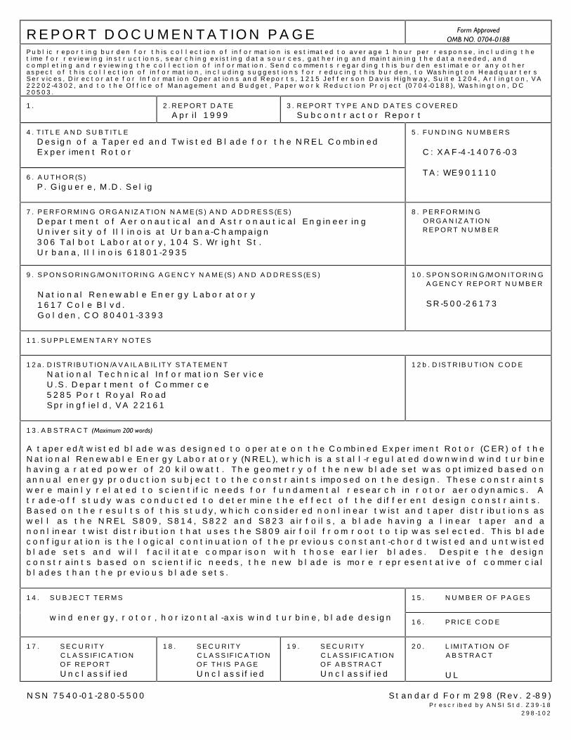
REPORT DOCUMENTATION PAGE Form ApprovedOMB NO. 0704-0188
Public reporting burden for this collection of information is estimated to average 1 hour per response, including thetime for reviewing instructions, searching existing data sources, gathering and maintaining the data needed, andcompleting and reviewing the collection of information. Send comments regarding this burden estimate or any otheraspect of this collection of information, including suggestions for reducing this burden, to Washington HeadquartersServices, Directorate for Information Operations and Reports, 1215 Jefferson Davis Highway, Suite 1204, Arlington, VA22202-4302, and to the Office of Management and Budget, Paperwork Reduction Project (0704-0188), Washington, DC20503.
1. 2.REPORT DATEApril 1999
3. REPORT TYPE AND DATES COVEREDSubcontractor Report
4. TITLE AND SUBTITLEDesign of a Tapered and Twisted Blade for the NREL CombinedExperiment Rotor
6. AUTHOR(S)P. Giguere, M.D. Selig
5. FUNDING NUMBERS
C: XAF-4-14076-03
TA: WE901110
7. PERFORMING ORGANIZATION NAME(S) AND ADDRESS(ES)Department of Aeronautical and Astronautical EngineeringUniversity of Illinois at Urbana-Champaign306 Talbot Laboratory, 104 S. Wright St.Urbana, Illinois 61801-2935
8. PERFORMINGORGANIZATIONREPORT NUMBER
9. SPONSORING/MONITORING AGENCY NAME(S) AND ADDRESS(ES)
National Renewable Energy Laboratory1617 Cole Blvd.Golden, CO 80401-3393
10.SPONSORING/MONITORINGAGENCY REPORT NUMBER
SR-500-26173
11.SUPPLEMENTARY NOTES
12a. DISTRIBUTION/AVAILABILITY STATEMENTNational Technical Information ServiceU.S. Department of Commerce5285 Port Royal RoadSpringfield, VA 22161
12b. DISTRIBUTION CODE
13. ABSTRACT (Maximum 200 words)
A tapered/twisted blade was designed to operate on the Combined Experiment Rotor (CER) of theNational Renewable Energy Laboratory (NREL), which is a stall-regulated downwind wind turbinehaving a rated power of 20 kilowatt. The geometry of the new blade set was optimized based onannual energy production subject to the constraints imposed on the design. These constraintswere mainly related to scientific needs for fundamental research in rotor aerodynamics. Atrade-off study was conducted to determine the effect of the different design constraints. Based on the results of this study, which considered nonlinear twist and taper distributions aswell as the NREL S809, S814, S822 and S823 airfoils, a blade having a linear taper and anonlinear twist distribution that uses the S809 airfoil from root to tip was selected. This bladeconfiguration is the logical continuation of the previous constant-chord twisted and untwistedblade sets and will facilitate comparison with those earlier blades. Despite the designconstraints based on scientific needs, the new blade is more representative of commercialblades than the previous blade sets.
15. NUMBER OF PAGES
14. SUBJECT TERMS
wind energy, rotor, horizontal-axis wind turbine, blade design 16. PRICE CODE
17. SECURITYCLASSIFICATIONOF REPORTUnclassified
18. SECURITYCLASSIFICATIONOF THIS PAGEUnclassified
19. SECURITYCLASSIFICATIONOF ABSTRACTUnclassified
20. LIMITATION OFABSTRACT
UL
NSN 7540-01-280-5500 Standard Form 298 (Rev. 2-89)Prescribed by ANSI Std. Z39-18
298-102